

Poulan PPG6000, 2006-08 Owner's Manual
Portable Electric Generator
Service Manual
Model: PPG6000

Contents
Chapter 1 General Information…………………………………………….. 3-7
General Description of Generator…………………………………. 3
Safety Information…………………………………………………… 4
Model Parameters…………………………...………………………. 5
Maintenance and Adjusting Data……………..……………………. 5-7
Chapter 2 Maintenance of the Generator Set………………………………8
2.1 Maintenance of Starting System……………………………….. 8-10
2.2 Maintenance of Lubrication System…………………………… 10-11
2.3 Maintenance of Inlet System…………………………………… 12-13
2.4 Maintenance of Fuel System………………..………………… 13-14
2.5 Maintenance of Exhaust System……………………………… 14-15
2.6 Maintenance of Ignition System……………………………….. 16-17
2.7 Maintenance of Generator………………………………………18-20
2.8 Maintenance of Cylinder Head and Valve……………………. 20-24
2.9 Maintenance of Crankcase, Crankshaft and Camshaft……... 25-28
2.10 Maintenance of Connecting Rod, Piston and Cylinder…….. 29-31
2.11 Electrical System ………...................................................... 32
2.12 Wiring Diagram…………………………………………………. 33
Chapter 3 Trouble Shooting…................................................................. 34
3.1 General…………………………………………………………… 34
3.2 Hard Starting…………………………………………………….. 35
3.3 Ignition System……………………………………………………35
3.4 Generator Power Flow Chart…………………………………… 36
3.5 Electrical Troubleshooting Stator……………………………… 37
3.6 General Troubleshooting……………………………………….. 38
Chapter 4 Exploded View and Bill of Materials (BOM)………………….. 39
4.1 Exploded Views………………………………………………… 39-42
4.2 Bill of Materials (BOM)………………………………………….. 42-50
Chapter 1 General Information
PPG6000 Generator is equipped with a single cylinder, 4 stroke, forced air-cooled, OHV 25° slant,
internal combustion engine. It is equipped with an electronic ignition system and is tuned to meet all
EPA and California Emissions Requirements.
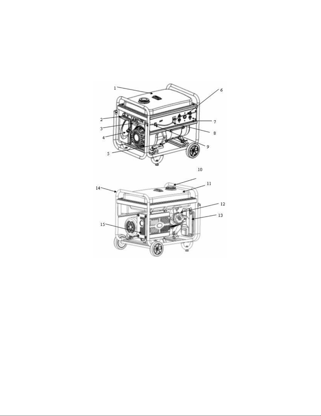
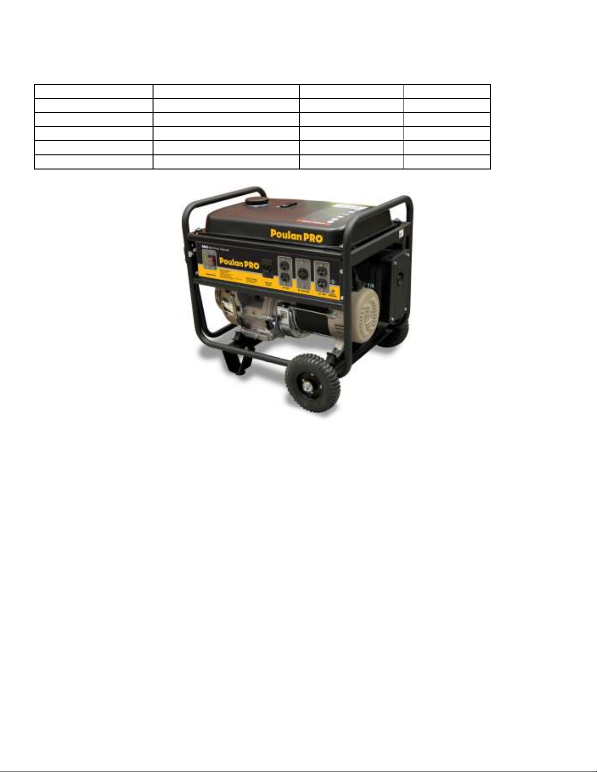
General Description:
1. Gas Tank
2. Choke
3. Fuel Shut Off
4. Pull Starter
5. Oil Dipstick
6. 120 Volt Outlet
7. Ground
8. Circuit Breaker
9. On Off Switch
10. Gas Cap
11. Gas Tank
12. Valve Cover
13. Air Filter
14. Frame
15. Muffler
Figure 1.1
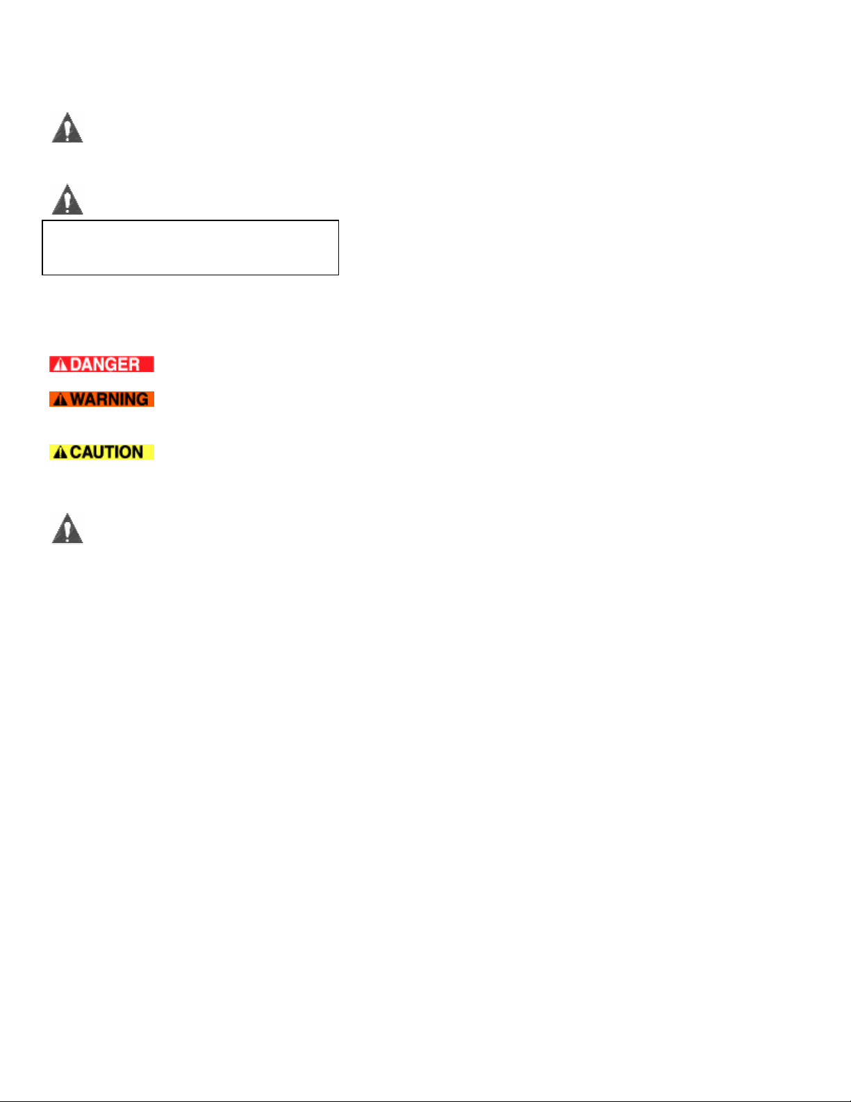
Safety Information:
This symbol is known as the safety alert symbol and points out safety instructions that can lead
to injury or death.
Attention:
Please read and understand this manual
and the safety information prior to
starting the Generator.
Danger: Indicates an imminently hazardous situation which, if not avoided, will result in death or serious injury.
Warning: Indicates a potentially hazardous situation which, if not avoided, could result in death or serious
injury.
Caution: Indicates a potentially hazardous situation which, if not avoided, may result in minor or moderate
injury.
SAFETY INSTRUCTIONS
This generator is designed to supply electrical power. Please read and understand all of the safety instructions
and warning labels associated with this generator.
1) Do not operate indoors.
2) Generator must be on a flat stable surface. Surface slope not to exceed 4 degrees.
3) Operate in a well-lit and ventilated area.
4) Do not operate in moist or wet conditions including the surrounding ground.
5) The generator should be a minimum of 3 feet away from all combustible materials and should not be used
around hazardous materials.
6) Operating at a gas or natural gas filling station is forbidden.
7) Do not touch muffler or cylinder during or after operation. They are hot.
8) No smoking when filling the gas tank.
9) Do not overflow gas tank. Fill the tank to 1 inch below the top neck to allow for gas expansion. Ensure the
ventilation hole in the gas cap is not plugged with foreign matter such as dirt or leaves.
10) The engine should be shut off for at least 2 minutes before adding gas or oil.
11) Do not open the gas tank or oil reservoir while the engine is running.
12) Be mindful of the danger, warning and caution labels on the generator.
13) Keep away from children. Children should be kept at a minimum of 6 feet away from the generator at all
times.
14) In a normal situation the generator should be shut off using the instructions found on the front panel label.
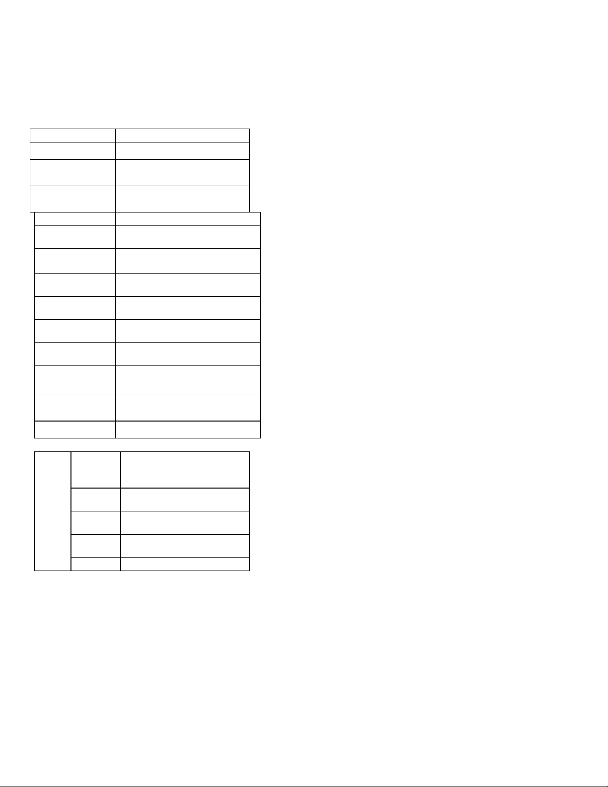
Specifications
PPG6000
Dimension/Weight Engine
Model PPG6000
LxHxW - Inches
26.8x20x21.3
Net Weight, Box Incl.
Gross Weight, Full of
Fuel
Model OHV13H
Engine Type
Cylinder discharge
capacity
Bore x Stroke
Cooling System
Ignition System
Spark Plug
Engine Oil Volume
Fuel Volume)
Compression Ratio
Model
Rated
Voltage
Rated
Frequency
Rated
Current
185lb
220lb
4-stroke, overhead valve, cylinder tilt 25°
389 cc
88x64 mm
Forced Air Cooling
Transistor Magnet Ignition
NGK, BP6ES
1.1Qt
6.6 Gallon
8.0:1
PPG6000
120V / 240V
60HZ
27.2A
Rated Output
Max Output
6.0KW
6.3KW
834KPa@600RPM
Generator
Tolerance Parameters
Parts Item Standard Extreme Max/Min
Cylinder
Crankshaft
Crankshaft case cover
spark plug
spark plug capacity
Maintenance and Adjusting Data
Max Speed
Cylinder Pressure
Cylinder bore diameter
Warpage
Valve bushing
Outside Diameter of piston skirt
Gap of piston and cylinder
Inside diameter of piston pin hole
Outside diameter of piston pin
Clearance of piston and piston pin hole
Flank clearance of Piston ring
Closed gap of the first and second ring
Closed gap of the oil ring
Width of the first ring
Width of the oil ring
Small end diameter
Large end diameter
Large end clearance
Large end flank clearance
Crankshaft pin outside diameter
Intake valve adjusted clearance
Exhaust valve adjusted clearance
Intake valve stem diameter
Exhaust valve stem diameter
Valve guide inside diameter
Clearance of intake valve and guide
Clearance of exhaust valve and guide
Valve seat width
Spring free length
Intake valve cam height
Exhaust valve cam height
Camshaft collar
Camshaft hole
Spark plug gap
Resistance
Resistance of primary coil
Resistance of secondary coil
Air Gap
3750+ 150, No Load
588-
85-120PSI@600PSI
88.00mm, 3.465" 88.17mm, 3.471"
.10mm, .004"
6.60mm, .260" 6.75mm, .2657"
87.985mm, 3.464" 87.85mm, 3.459"
.015-.052mm, .001" .12mm, .005"
20.002mm, .787" 20.042mm, .789"
20.00mm, .787" 19.95mm, .785"
.002-.014mm, .0006" .08mm, .003"
.030-.060mm, .002" .15mm, .006"
.20-.40mm, .012" 1.0mm, .039"
.20-.70mm, .002" 1.0mm, .039"
2.0mm, .079" 1.75mm, .069"
2.8mm, .110" 2.7mm, .106"
20.005mm, .7876" 20.07mm, .790"
36.025mm, 1.418" 36.070mm, 1.420"
.040-.066mm, .002" .12mm. .005"
.1-.7mm, .019" 1.0mm, .039"
35.985mm, 1.4167" 35.93mm, 1.4146"
.15+.02mm,
.006+.001"
.20+.02mm,
.008+.001"
6.59mm, .259" 6.44mm, .253"
6.55mm, .258" 6.40mm, .252"
6.60mm, .260" 6.66mm, .262"
.010-.037mm, .001" .10mm, .004"
.050-.077mm, .002" .12mm, .005"
1.1mm, .043" 2.0mm, .079"
39.0mm, 1.535" 37.5mm, 1.476"
32.44-32.60mm,
1.279"
31.94-32.10mm,
1.260"
15.984mm, .6292" 15.92mm, .6268"
16.0mm, .6299" 16.05mm, .6318"
0.7-0.8mm, .027.031"
7.5-12.5K ohms
.8-1.0 ohms
5.9-7.5 ohms
.4+.2mm, .016+.007"
-
-
32.24mm, 1.269"
31.74mm, 1.249"
Torque Values
Torque Torque
Connecting rod bolt
Cylinder head bolt
Flywheel nut
Rocker shaft nut
Rocker shaft bolt
Fuel switch connecting nut
Exhaust pipe connecting
nut/bolt
Air filter bolts
Air filter nut
Drain plug
Rotor bolt
Standard Torque Values
M8X1.25(special bolt)
M10X1.25
M16X1.5(special nut)
M6X.5
M8X1.25(special bolt)
M10X1.25
M8X1.25
M6X1.0
M6X1.0
M12X1.25
M10X210
M5
M6
M8
M10
M12
M6
M8
M10
M12
M5
M6
N/m
14 124
34 300
113 *83 ft*lbf
10 88
24 212
10 88
24 212
7.5 66
8.5 75
23 203
44 389
5 44
10 88
24 212
37 327
55 487
12 106
26 230
34 300
59 522
4 35
9 79
in*lbf *except
where note
Fitting Directions:
1. When fitting the piston in the cylinder the mark “ ” on the piston top must be aimed to the intake
valve direction (upper).
2. When fitting the piston rings on the piston the “R,N’ mark on the first and second ring must be
upwards, and the gap of all three rings should be 120° apart.
3. The timing marks on the gears must be matched to each other.
Generator Information
Area
Main Winding
Field Winding
Exciter Winding
Main Winding
Carbon Brush length
Item Standard Service Limit
Resistance .2 ohms
Resistance 52-62 ohms
Resistance 1.2 ohms
Resistance .4 ohms
Length .9mm, .354" 5mm, .197"
EPA and Engine Serial Number are located on the panel side of the generator in the location shown.
Chapter 2 Maintenance of the Generator Set
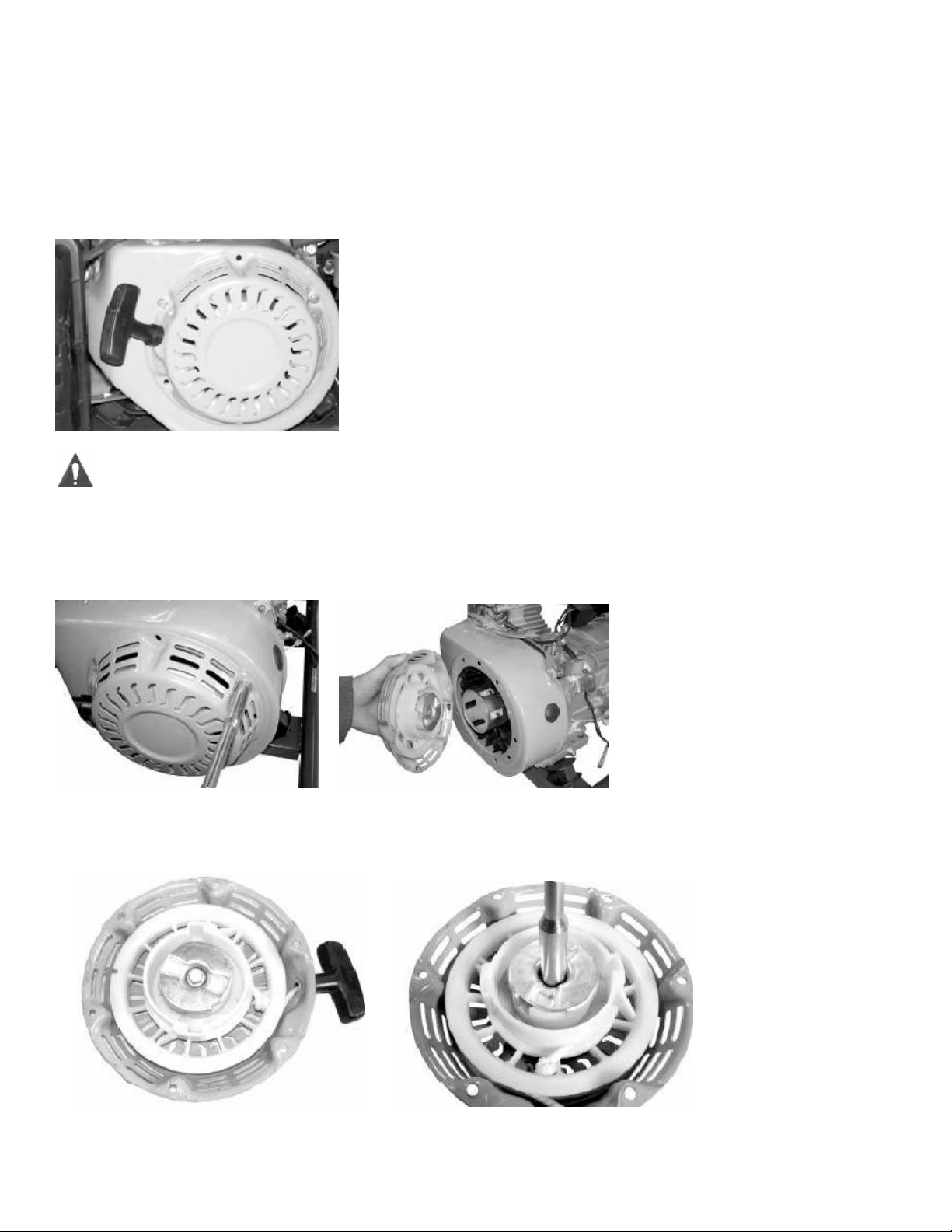
2.1 Maintenance of the Manual Starting System
The integral configuration of the starting device is shown below. Check the condition of the starter.
Replace if damaged.
There is a spring inside the starter device that is under stress. Wear safety goggles and watch
for flying debris when it is removed.
Remove the perimeter bolts to remove the starter housing.
Check the condition of the starter system. Replace any broken or damaged parts as follows:
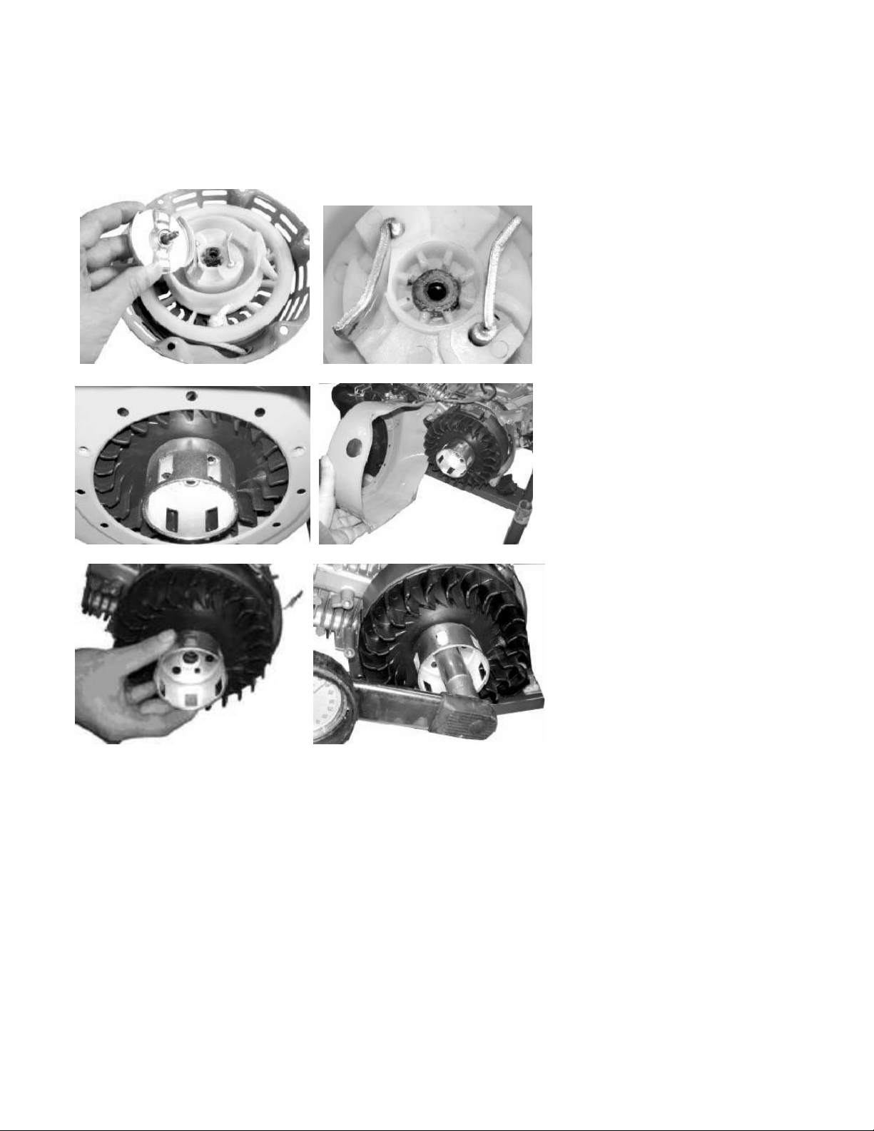
1. Inspect the rope for abrasions. Replace as necessary.
2. Dismantle the starter pawl guide bolt with a socket.
3. Remove the pawls and pawl spring.
4. Visually inspect all parts.
5. Inspect the flute of the starting draw wheel.
6. Remove the shroud from the engine for inspection of the fan blades.
7. Replace parts as necessary.
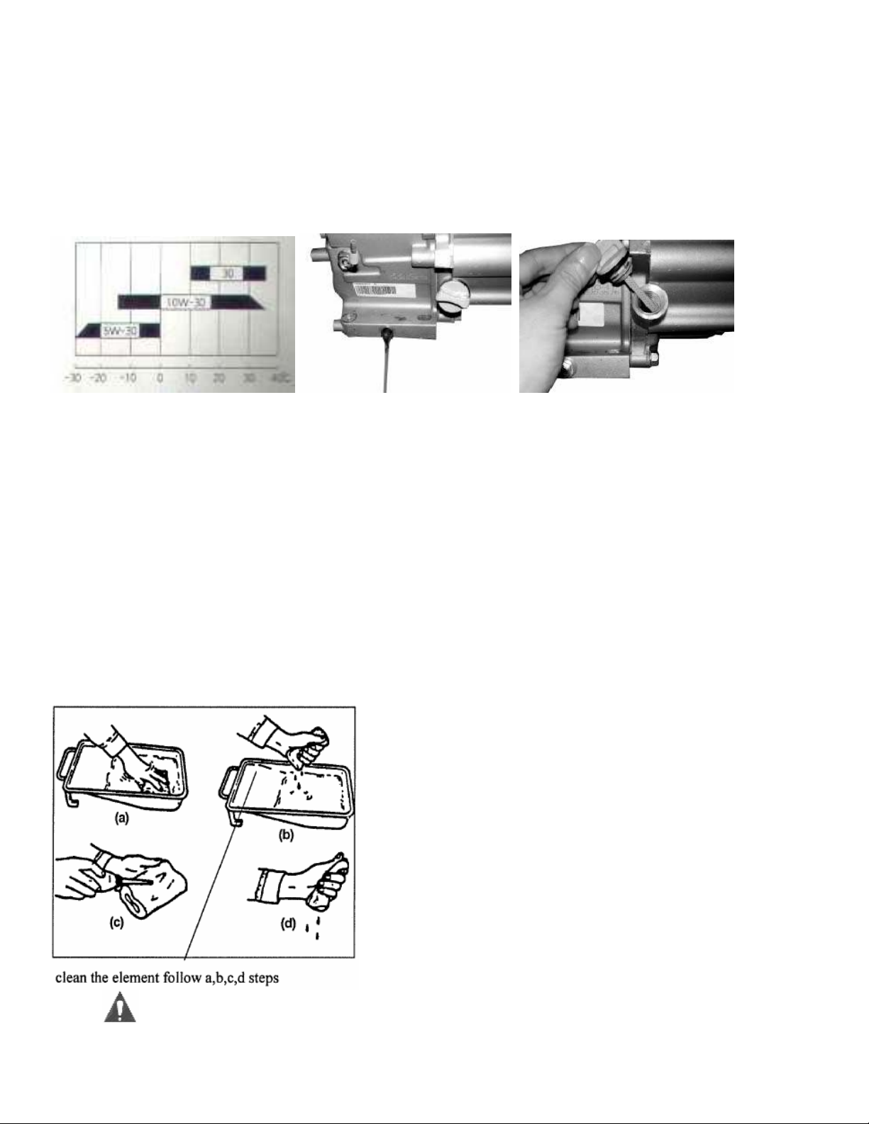
2.2 Maintenance of the Lubrication System
Chose the oil type according to the local temperature of operation.
Use Four-stroke engine oil. SE, SF or equivalent to SG grade oil (SAE-30). When temp is below
50°F SAE 10W30 is recommended. SAE 5W-30 is recommended when temp is below 5°F.
1. It is best to change the engine oil when the engine is warm. This allows the oil to flow better for
a complete drain.
2. Drain the oil from the cylinder block by removing the plug at the base of the engine.
3. Check the condition of the dipstick and o-ring seal.
4. Replace the drain plug.
5. Fill with oil. See specifications in section 1.1 (parameters) for amount to add.
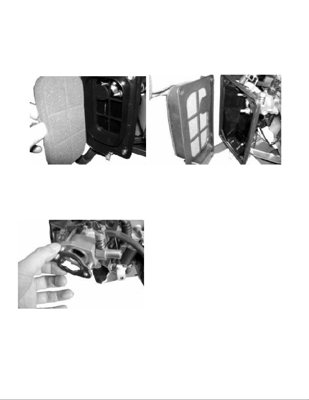
2.3 Maintenance of the Inlet system
1. Remove the air cleaner outer cover by releasing the latches at the top and bottom.
2. Remove the air cleaner element (foam pad). Replace as necessary.
Never use gasoline, low-burning point solvent, acid or alkaline to clean the element. Use
detergent only!
Cleaning the element (foam pad)
Dip the element in the detergent and wring it out. Apply motor oil and wring out excess oil. Install
element.
3. Remove the plastic inner housing by removing the six nuts around the perimeter.
4. Remove the enclosure by removing the two nuts inside the enclosure and one on the
backside.
5. Remove the carburetor gasket and choke mechanism. Some models may not have automatic
chokes and the choke mechanism will not need to be removed. It is built onto the carburetor in
this case.
6. Remove the lines to the carburetor and remove the carburetor.
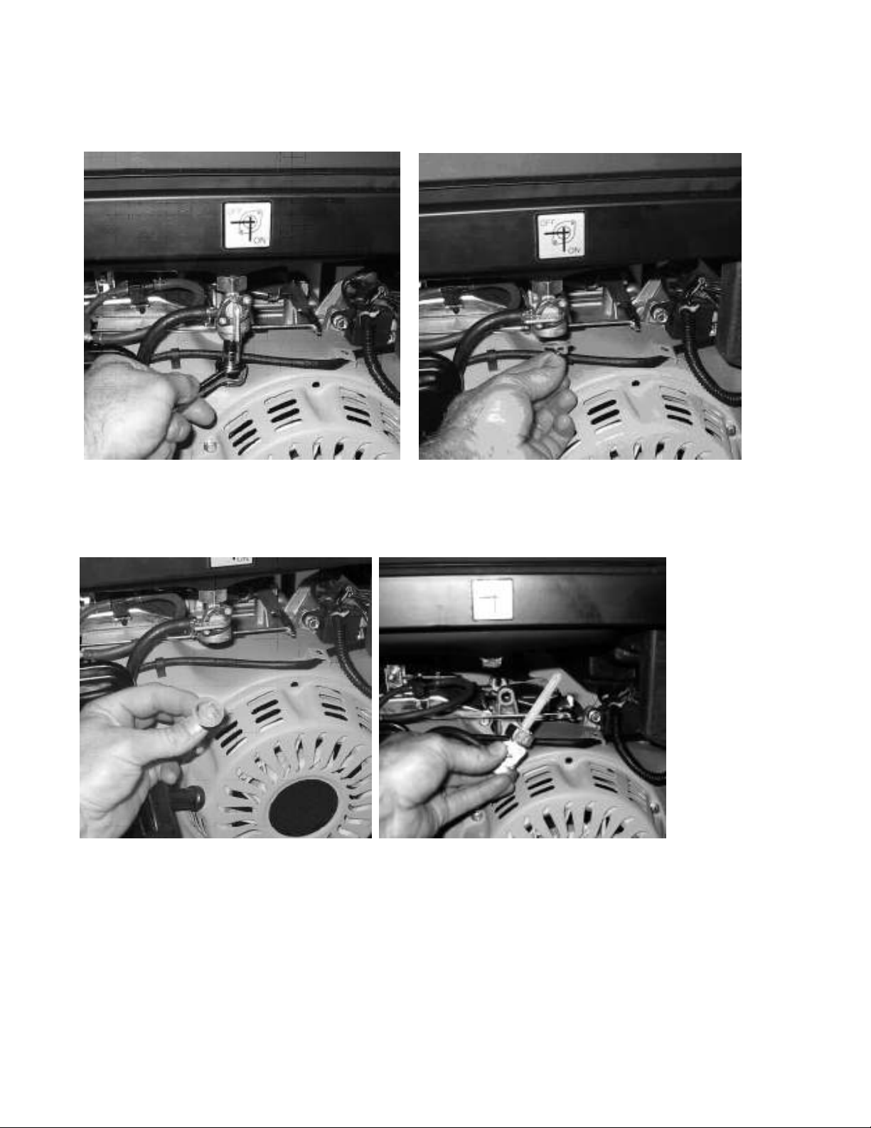
2.4 Maintenance of Fuel System
1. Remove the bowl of the fuel cock.
2. Remove the screen inside the fuel cock.
3. Remove the fuel cock.
4. Pull out the screen inside the tank.
5. Clean or replace both screens and reassemble.
 Loading...