

Poulan Pro PPCRT17, PPCRT14 Operator's Manual

IMPORTANT MANUAL Do Not Throw Away
OPERATOR'S MANUAL
MODEL:
PPCRT17
REAR TINE TILLER
ALWAYS WEAR EYE PROTECTION DURING OPERATION
Visit our website: www.poulanpro.com
Gasoline containing up to 10% ethanol (E10) is acceptable for use in this machine.
The use of any gasoline exceeding 10% ethanol (E10) will void the product warranty.
115 78 55-32 Rev. 3 Printed in U.S.A.
WARNING:
Read this Man u al and follow all Warnings and Safety Instructions. Fail ure
to do so can re sult in serious in ju ry.
10.11.17 SR

SAFETY RULES
SAFE OPERATION PRACTICES FOR POWERED WALK-BEHIND ROTARY
TILLERS AND HAND-SUPPORTED CULTIVATORS
TRAINING
• Read, understand, and follow all instructions on the
machine and in the manual(s) before starting. Be
thoroughly familiar with the controls and the proper
use of the equipment. Know how to stop the machine
and disengage the controls quickly.
• Never allow children to operate the equipment. Never
allow adults to op er ate the equipment without proper
instruction.
• Keep the area of operation clear of all persons, par tic u lar ly small children, and pets.
PREPARATION
• Thoroughly inspect the area where the equipment is
to be used and remove all foreign objects.
• Disengage all clutches and shift into neutral before
starting the engine (mo tor).
• Do not operate in shorts or open toed shoes. Wear
proper Personal Protective Equipment (PPE) at all
times, such as gloves, proper footwear, and eye protection.
• Use extension cords and receptacles as specified by
the manufacturer for all machines with electric drive
motor or electric starting motors.
• Never attempt to make any adjustments while the
engine (motor) is running (except where specifically
recommended by the manufacturer).
SAFE HANDLING OF GASOLINE:
• To avoid personal injury or property damage, use extreme care in handling gasoline. Gasoline is extremely
flammable and the vapors are explosive.
• Extinguish all cigarettes, cigars, pipes, and other
sources of ignition.
• Use only an approved gasoline container.
• Never remove gas cap or add fuel with the engine
running.
• Allow engine to cool before refueling.
• Never refuel the machine indoors.
• Never store the machine or fuel container where there
is an open flame, spark, or pilot light such as on a water
heater or other appliance.
• Never fill containers inside a vehicle of on a truck or
trailer bed with a plastic liner. Always place containers
on the ground away from your vehicle before filling.
• Remove gas powered equipment from the truck or
trailer and refuel it on the ground. If this is not possible,
then refuel such equipment with a portable container,
rather than from a gasoline dispenser nozzle.
• Keep the nozzle in contact with the rim of the fuel tank or
container opening at all times until fueling is complete.
Do not use a nozzle lock open device.
• If fuel is spilled on clothing, change clothing immediately.
• Never overfill fuel tank. Replace gas cap and tighten
securely.
• If fuel is spilled, do not attempt to start engine but move
the machine away from the area of spillage and avoid
creating any source of ignition until fuel vapors have
dissipated.
OPERATION
• Do not allow hands, feet, or other body parts or clothing near the rotating tines or any other moving part.
The tines begin to rotate once the engine/motor is
started and the activating device is engaged. The tines
may momentarily rotate after the activating device is
released.
• Exercise extreme caution when crossing gravel surfaces. Stay alert for hidden hazards or traffic.
• After striking a foreign object, stop the engine (motor),
remove the wire from the spark plug (or disconnect)
the cord for electric products), thoroughly inspect the
machine for any damage, and repair the damage before
restarting and operating the machine.
• Exercise caution to avoid slipping or falling.
• If the machine should start to vibrate abnormally, stop
the engine (motor) and check immediately for the cause.
Vibration is general a warning sign of trouble.
• Stop the engine (motor) when leaving the operating
position, before unclogging the tines, and when making
any repairs, adjustments, and inspections.
• Stop the engine (motor) when leaving the machine
unattended.
• Before cleaning, repairing, or inspecting, shut off the
engine and make certain all moving parts have stopped.
Disconnect the spark plug wire, and keep the wire away
from the plug to prevent accidental starting. Disconnect
the cord on electric motors.
• Do not operate the engine in a confined space where
dangerous carbon monoxide fumes can collect.
• Never operate the machine without proper shields and
guards or other safety protective devices in place.
• Do not overload the machine capacity by attempting
to till or cultivate too deep at too fast a rate.
• Never operate the machine at high transport speeds
on hard or slippery surfaces.
• Never allow bystanders near the machine, especially
small children.
• Use only attachments and accessories approved by the
manufacturer of the machine (such as wheel weights,
counterweights, and the like).
• Never operate the tiller without good visibility or light.
• Be careful when tilling in hard ground. The tines may
catch in the ground and propel the tiller forward. If this
occurs, let go of the handlebars and do not restrain the
machine.
• Use extreme caution when reversing or pulling the
machine towards you. To avoid getting pinned against
a structure, ensure adequate distance before reversing near a wall or fence. For machines with powered
reverse drive capability, familiarize yourself with the
operation of the Emergency Stop Control. It provides
a secondary means of stopping power to the tines and
wheel drive in an emergency.
• Do not change the engine governor settings or over
speed the engine.
• Start the engine or switch on the motor carefully according to instructions and with feet away from the tines.
2
SAFETY RULES
SAFE OPERATION PRACTICES FOR POWERED WALK-BEHIND ROTARY
TILLERS AND HAND-SUPPORTED CULTIVATORS
• Never pick up or carry a machine while the engine
(motor) is running.
• Do not operate the tiller while under the influence of
alcohol or drugs.
• Powered walk-behind tiller work is strenuous. You must
be in good physical condition and mentally alert. If you
have any condition that might be aggravated by strenuous work, check with your doctor before operating a
powered walk-behind tiller.
MAINTENANCE AND STORAGE
• Keep machine, attachments, and accessories in safe
working condition.
• Check shear bolts, engine mounting bolts, and other
bolts at frequent intervals for proper tightness to be
sure the equipment is in safe working condition.
• Never store the machine with fuel in the fuel tank inside
a building where ignition sources are present, such
as hot water and space heaters, clothes dryers, and
the like. Allow the engine to cool before storing in any
enclosure.
• Always refer to the operator’s manual for important
details if the tiller is to be stored for an extended period.
• If the fuel tank has to be drained, do this outdoors.
• Follow the manufacturer’s recommendations for safe
loading, unloading, transport, and storage of machine.
- IMPORTANT -
CAUTIONS, IMPORTANTS, AND NOTES ARE A MEANS OF
ATTRACTING ATTENTION TO IMPORTANT OR CRIT I CAL
IN FOR MA TION IN THIS MANUAL.
IMPORTANT: USED TO ALERT YOU THAT THERE IS A
POS SI BIL I TY OF DAM AG ING THIS EQUIP MENT.
NOTE: Gives essential information that will aid you to
better understand, incorporate, or execute a particular set
of instructions.
Look for this symbol to point out im por tant safety precautions. It means
CAUTION!!! BE COME ALERT!!! YOUR
SAFE TY IS INVOLVED.
CAUTION: Always disconnect spark
plug wire and place wire where it can not contact spark plug in order to pre vent ac ci den tal starting when setting
up, trans port ing, adjusting or making
re pairs.
WARNING
The engine exhaust from this product con tains
chem i cals known to the State of Cal i for nia to
cause cancer, birth defects, or other reproductive harm.
3

PRODUCT SPECIFICATIONS
GASOLINE CAPACITY: 1.47 Quarts (1,4 L)
Unleaded Reg u lar
OIL (API SJ–SN): SAE 30 (Above 32°F/0°C)
(Capacity: 16 oz./0,47L) SAE 5W-30 (Below 32°F/0°C)
SPARK PLUG : NGK BPR6ES
(GAP: .010"/0.25mm) TORCH F6RTC
CONGRATULATIONS on your purchase of a new tiller. It
has been designed, en gi neered and manu fac tured to give
you the best pos sible de penda bil ity and per form ance.
Should you experience any prob lems you can not easily
remedy, please contact your nearest authorized service
center. We have com pe tent, well-trained tech ni cians and
the proper tools to service or repair this unit.
Please read and retain this manual. The in struc tions will
enable you to assemble and main tain your tiller prop erly.
Always observe the “SAFETY RULES”.
CUSTOMER RESPONSIBILITIES
• Read and observe the safety rules.
• Follow a regular schedule in maintaining, caring for
and using your tiller.
• Follow instructions under “Maintenance” and “Stor age”
sections of this Owner’s Manual.
IMPORTANT: THIS UNIT IS EQUIPPED WITH AN INTERNAL
COMBUSTION ENGINE AND SHOULD NOT BE USED ON
OR NEAR ANY UNIMPROVED FOREST-COVERED, BRUSHCOVERED OR GRASS COVERED LAND UNLESS THE ENGINE'S
EXHAUST SYSTEM IS EQUIPPED WITH A SPARK ARRESTER
MEETING APPLICABLE LOCAL LAWS (IF ANY). IF A SPARK
ARRESTER IS USED, IT SHOULD BE MAINTAINED IN EFFECTIVE
WORK ING ORDER BY THE OPERATOR.
IN THE STATE OF CALIFORNIA, A SPARK ARRESTER IS
REQUIRED BY LAW (SECTION 4442 OF THE CALIFORNIA
PUBLIC RESOURCES CODE). OTHER STATES MAY HAVE
SIMILAR LAWS. FEDERAL LAWS APPLY ON FEDERAL LANDS.
SEE YOUR AUTHORIZED SERVICE CENTER/DEPARTMENT
FOR SPARK ARRESTER.
SUPPORT / HELP
If you require assistance or have questions concerning the application, operation, maintenance or parts for your product:
• Visit our website: www.poulanpro.com
• Call Us Toll Free: 1-800-849-1297
TABLE OF CONTENTS
SAFETY RULES .........................................................2
CUSTOMER RESPONSIBILITIES .............................4
PRODUCT SPECIFICATIONS ...................................4
ASSEMBLY .............................................................. 5-7
OPERATION ..........................................................8-12
MAINTENANCE SCHEDULE ...................................13
MAINTENANCE .................................................13-15
SERVICE & ADJUSTMENTS ..............................16-18
STORAGE ................................................................19
TROUBLESHOOTING .............................................. 20
4
ASSEMBLY
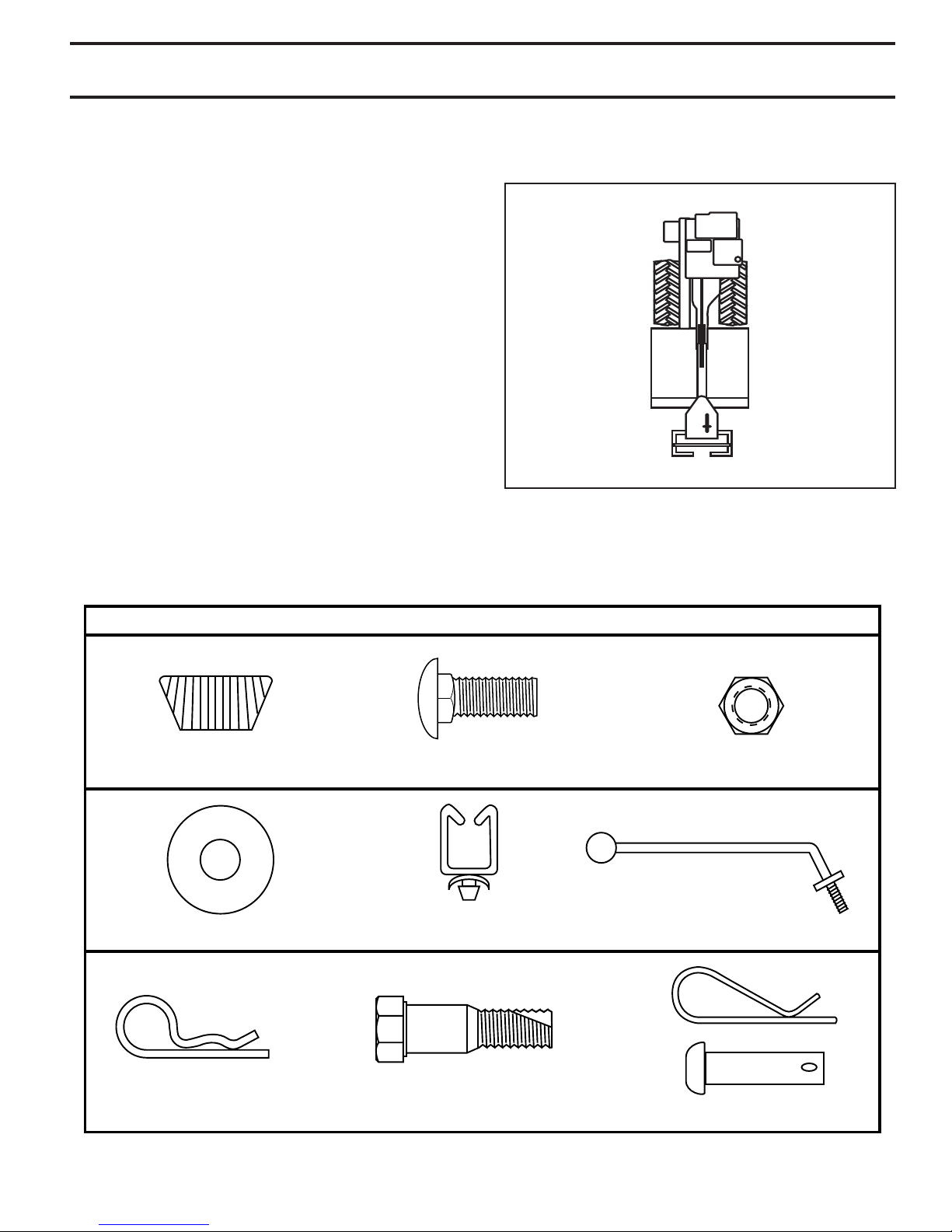
(2) Hairpin Clips
(1) Cable Clip
(1) Carriage Bolt 3/8-16 UNC x 1 Gr. 5
(1) Center Locknut 3/8-16 UNC
(1) Handle Lock Lever
(2) Handle Locks
(1) Flat Washer 13/32 x 1 x 11 Ga.
CONTENTS OF HARDWARE PACK
(1) Pivot Bolt
3/8-16 UNC Grade 5
Extra Shear Pins & Clips
Your new tiller has been assembled at the factory with exception of those parts left unassembled for shipping purposes.
To ensure safe and proper operation of your tiller all parts and hardware you assemble must be tightened securely. Use
the correct tools as necessary to insure proper tightness.
TOOLS REQUIRED FOR ASSEMBLY
A socket wrench set will make assembly easier. Stan dard
wrench sizes are listed.
(1) Utility knife
(1) Wire cutter
(1) Screwdriver
(1) Tire pressure gauge
(1) Pair of pliers
(1) 9/16" wrench
(2) 1/2" wrenches
OPERATOR’S POSITION (See Fig. 1)
When right or left hand is mentioned in this manual, it
means when you are in the operating position (standing
behind tiller handles).
FRONT
LEFT
OPERATOR’S POSITION
Fig. 1
RIGHT
overhead_views_1
5
ASSEMBLY
UNPACKING CARTON (See Fig. 2)
CAUTION: Be careful of exposed sta ples
when handling or disposing of cartoning material.
IMPORTANT: WHEN UN PACK ING AND AS SEM BLING
TILLER, BE CAREFUL NOT TO STRETCH OR KINK CABLES.
• While holding handle assembly, cut cable ties se cur ing
handle assembly to top frame. Let handle assembly
rest on tiller.
• Remove top frame of carton.
• Slowly ease handle assembly up and place on top of
carton.
• Cut down right hand front and right hand rear cor ners
of carton, lay side carton wall down.
• Remove packing material from handle assembly.
• Separate shift rod from handle assembly.
SHIFT ROD
HANDLE ASSEMBLY
"UP" POSITION
TIGHTEN HANDLE
LOCK LEVER TO
HOLD
LOOSEN HANDLE LOCK
LEVER TO MOVE
Fig. 4
carton_1
HANDLE
ASSEMBLY
Fig. 2
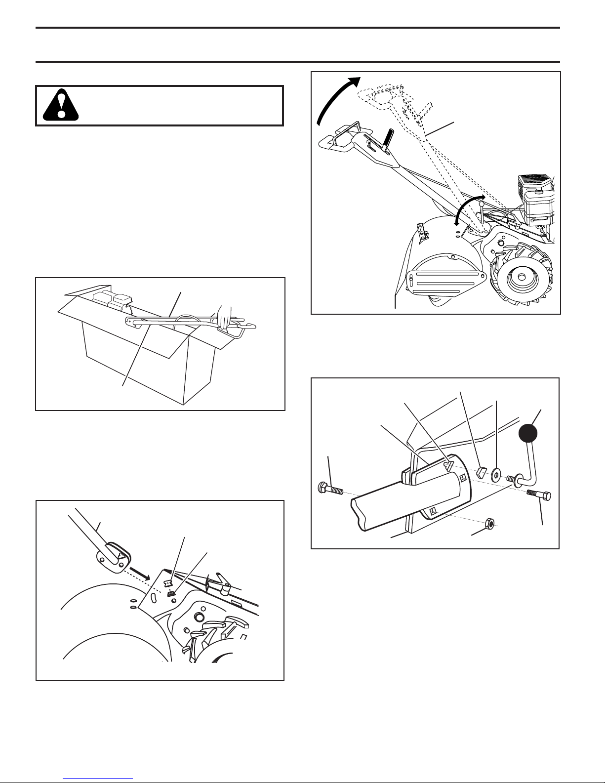
INSTALL HANDLE (See Figs. 3, 4, and 5)
• Insert one handle lock (with teeth facing outward)
in gearcase notch. (Apply grease on smooth side of
handle lock to aid in keeping lock in place until handle
assembly is lowered into position.)
HANDLE ASSEMBLY
GEARCASE NOTCH
HANDLE LOCK
(VIEWED FROM R.H. SIDE OF TILLER)
Fig. 3
• Grasp handle assembly. Hold in “up” position. Be sure
handle lock remains in gearcase notch. Slide handle
assembly into position.
• Rotate handle assembly down. Insert rear carriage
bolt first, with head of bolt on L.H. side of tiller and
loosely assemble locknut (See Fig. 5).
HANDLE
REAR
CARRIAGE
BOLT
GEARCASE
BASE
SLOT
HANDLE LOCK FLAT
WASHER
handles_34
LOCKNUT
HANDLE
Fig. 5
• Insert pivot bolt in front part of plate and tighten.
• Cut down remaining corners of carton and lay panels
flat.
• Lower the handle assembly. Tighten nut on carriage
bolt so handle moves with some resistance. This will
allow for easier adjustment.
• Place flat washer on threaded end of handle lock le ver.
• Insert handle lock lever through handle base and
gearcase. Screw in handle lock lever just enough to
hold lever in place.
• Insert second handle lock (with teeth inward) in the
slot of the handle base (just inside of washer).
• Raise handle assembly to highest position and se cure ly
tight en handle lock lever by rotating clockwise. Leav ing han dle assembly in highest position will make it
6
easier to connect shift rod.
LOCK
LEVER
PIVOT
BOLT
ASSEMBLY
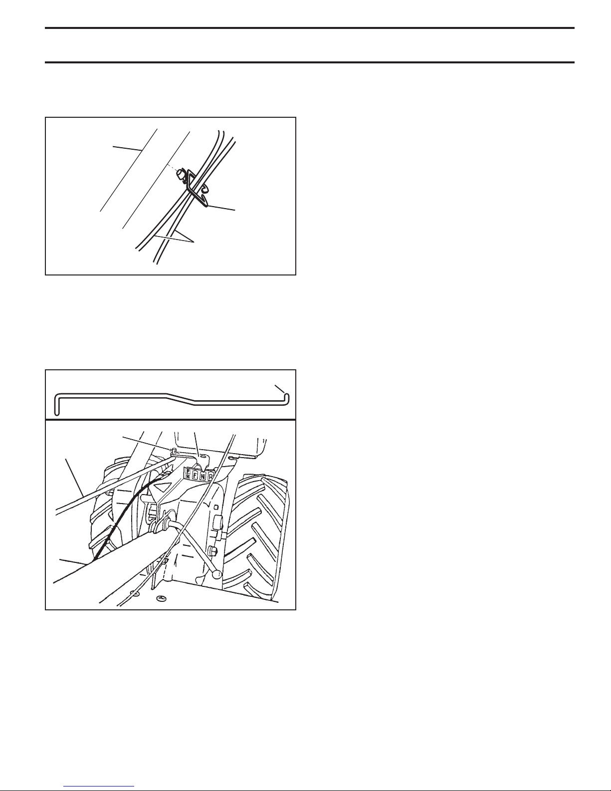
INSERT CABLE CLIP (See Fig. 6)
• Insert plastic cable clip into hole on the back of handle
column. Push cables into clip.
HANDLE
COLUMN
CABLE
CLIP
CABLES
Fig. 6
CONNECT SHIFT ROD (See Fig. 7)
• Insert end of shift rod farthest from bend into hole of
shift lever in di ca tor.
• Insert hairpin clip through hole of shift rod to secure
with bend of clip on right side.
REMOVE TILLER FROM CRATE
• Adjust handle assemby to lowest position. Be sure
lock lever is tightened securely.
• Make sure shift lever indicator is in “N” (neutral) po si tion (See Fig. 7)
• Tilt tiller forward by lifting handle. Separate cardboard
cover from leveling shield.
• Rotate tiller handle to the right and pull tiller out of
carton.
CHECK TIRE PRESSURE
The tires on your unit were overinflated at the factory for
shipping purposes. Correct and equal tire pressure is
important for best tilling performance.
• Make sure tires are properly inflated to the PSI shown
on tires.
HANDLE HEIGHT
• Handle height may be adjusted to better suit operator.
(See “TO ADJUST HANDLE HEIGHT” in the Service
and Adjustments section of this manual).
ATTACH THIS END TO SHIFT LEVER IN DI CA TOR
SHIFT ROD
HAIRPIN CLIP
SHIFT ROD
SHIFT LEVER INDICATOR
Fig. 7
7
OPERATION
KNOW YOUR TILLER
READ THIS OWNER'S MANUAL AND SAFETY RULES BEFORE OPERATING YOUR TILLER.
Compare the illustrations with your tiller to familiarize yourself with the location of various controls and adjustments. Save
this manual for future reference.
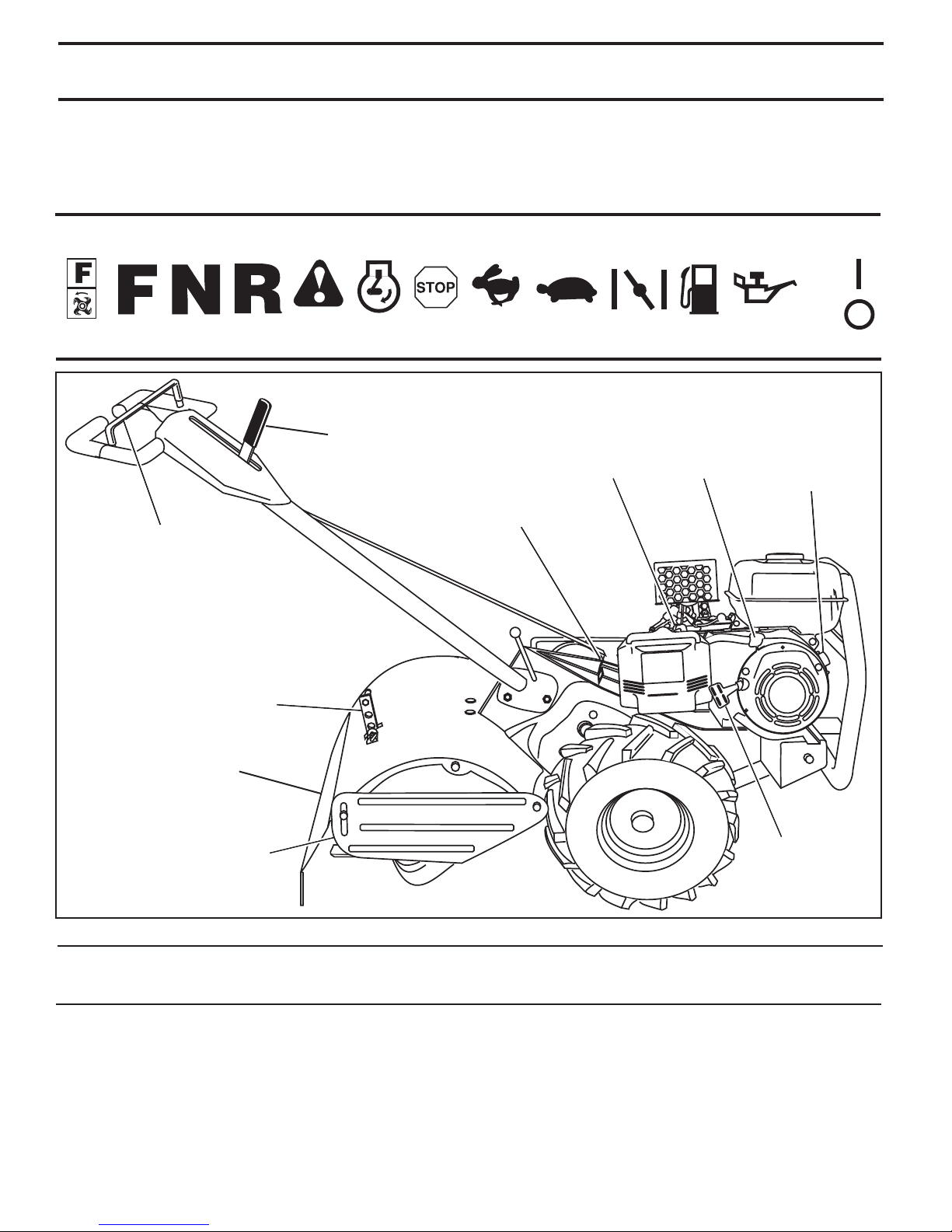
These symbols may appear on your Tiller or in literature supplied with the product. Learn and understand their
meaning.
RUN
TILLING
FORWARD
DRIVE
CONTROL
BAR
NEUTRAL /
EMERGENCY
DISENGAGE
DEPTH STAKE
LEVELING
SHIELD
REVERSE
OR WARNING
SHIFT/EMERGENCY
DISENGAGE LEVER
ENGINEONENGINE
OFF
FAST
SHIFT LEVER
IN DI CA TOR
SLOWCAUTION
CHOKE FUEL OIL
THROTTLE
CONTROL
FUEL
VALVE
STOP
ENGINE
ON/OFF
SWITCH
OUTER
SIDE SHIELD
MEETS ANSI SAFETY REQUIREMENTS
Our tillers conform to the safety standards of the American National Standards Institute.
ENGINE ON/OFF SWITCH - The engine switch enables
and disables the ignition system.
FUEL VALVE - The fuel valve opens and closes the passage between the fuel tank and the carburetor.
DEPTH STAKE - Controls depth at which tiller will dig.
DRIVE CONTROL BAR - Used to engage tines.
LEVELING SHIELD - Levels tilled soil.
OUTER SIDE SHIELD - Adjustable to protect small plants
from being buried.
RECOIL
STARTER
HANDLE
Fig. 8
RECOIL STARTER HANDLE - Used to start the engine.
SHIFT/EMERGENCY DISENGAGE LEVER - Used to
shift transmission gears and to disengage powered drive
and tines.
SHIFT LEVER INDICATOR - Shows which gear the trans mis sion is in.
THROTTLE CONTROL - Controls engine speed.
8
OPERATION
depth_
s
take
_2
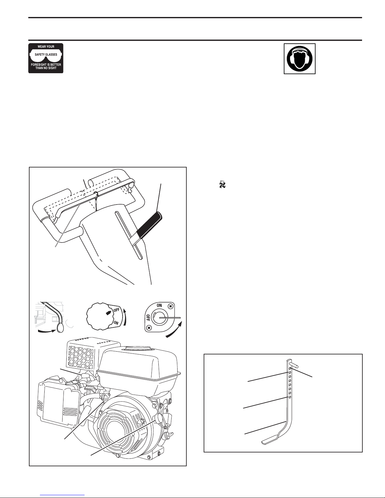
The operation of any tiller can result in foreign objects thrown into the eyes,
which can result in severe eye damage. Always wear safety glasses or eye
shields before starting your tiller and while tilling. We recommend a wide
vision safety mask over spectacles or standard safety glasses.
HOW TO USE YOUR TILLER
Know how to operate all controls before adding fuel and
oil or attempting to start engine.
STOPPING (See Fig. 9)
TINES AND DRIVE
• Release drive control bar to stop movement.
• Move shift / emergency disengage lever to “N” (neutral ) position.
IMPORTANT: TO STOP TINES AND POWERED DRIVE IN AN
EMERGENCY, MOVE SHIFT/EMERGENCY DISENGAGE LEVER
TO THE NEUTRAL/EMERGENCY DISENGAGE POSITION.
DRIVE CONTROL BAR
“ENGAGED” POSITION
SHIFT/EMERGENCY
DISENGAGE LEVER
Use ear protectors to avoid
damage to
hearing.
ENGINE
2. Move throttle control to “SLOW” po si tion and allow the
engine to run slowly for cool down.
3. Turn the engine switch to the "OFF" Position.
4. Turn the fuel valve lever to the "OFF" Position.
NOTE: NEVER USE CHOKE TO STOP ENGINE.
IMPORTANT: TO STOP ENGINE IN AN EMERGENCY, TURN
THE ENGINE SWITCH TO THE OFF POSITION.
TINE OPERATION - WITH WHEEL DRIVE
(See Fig. 9)
• Always release drive control bar before moving shift
lever into another position.
• Tine movement is achieved by moving shift lever to
( ) till position and engaging drive control bar.
FORWARD - WHEELS ONLY /
TINES STOPPED
• Release drive control bar and move shift lever in di ca tor to “F” (forward) position. Engage drive control bar
and tiller will move forward.
DRIVE CONTROL
BAR “DISENGAGED”
POSITION
THROTTLE
CONTROL
1
THROTTLE
CONTROL
ENGINE
SWITCH
FUEL
VALVE
REVERSE - WHEELS ONLY/TINES STOPPED
• DO NOT STAND DIRECTLY BEHIND TILLER.
• Release the drive control bar.
• Move throttle control to “SLOW” position.
• Move shift lever indicator to “R” (reverse) position.
• Hold drive control bar against the handle to start tiller
movement.
HARD TO SHIFT GEARS
• Briefly engage drive control bar and release or rock
tiller forward and backward until are able to shift gears.
DEPTH STAKE (See Fig. 10)
The depth stake can be raised or lowered to allow you
more versatile tilling and cul ti vat ing, or to more easily
transport your tiller.
SHALLOWEST
TILLING
(CULTIVATING)
DEEPEST
TILLING
TRANSPORT
POSITION
FUEL VALVE
ENGINE SWITCH
Fig. 9
DEPTH
STAKE
Fig. 10
9
OPERATION
epth
_stake_16
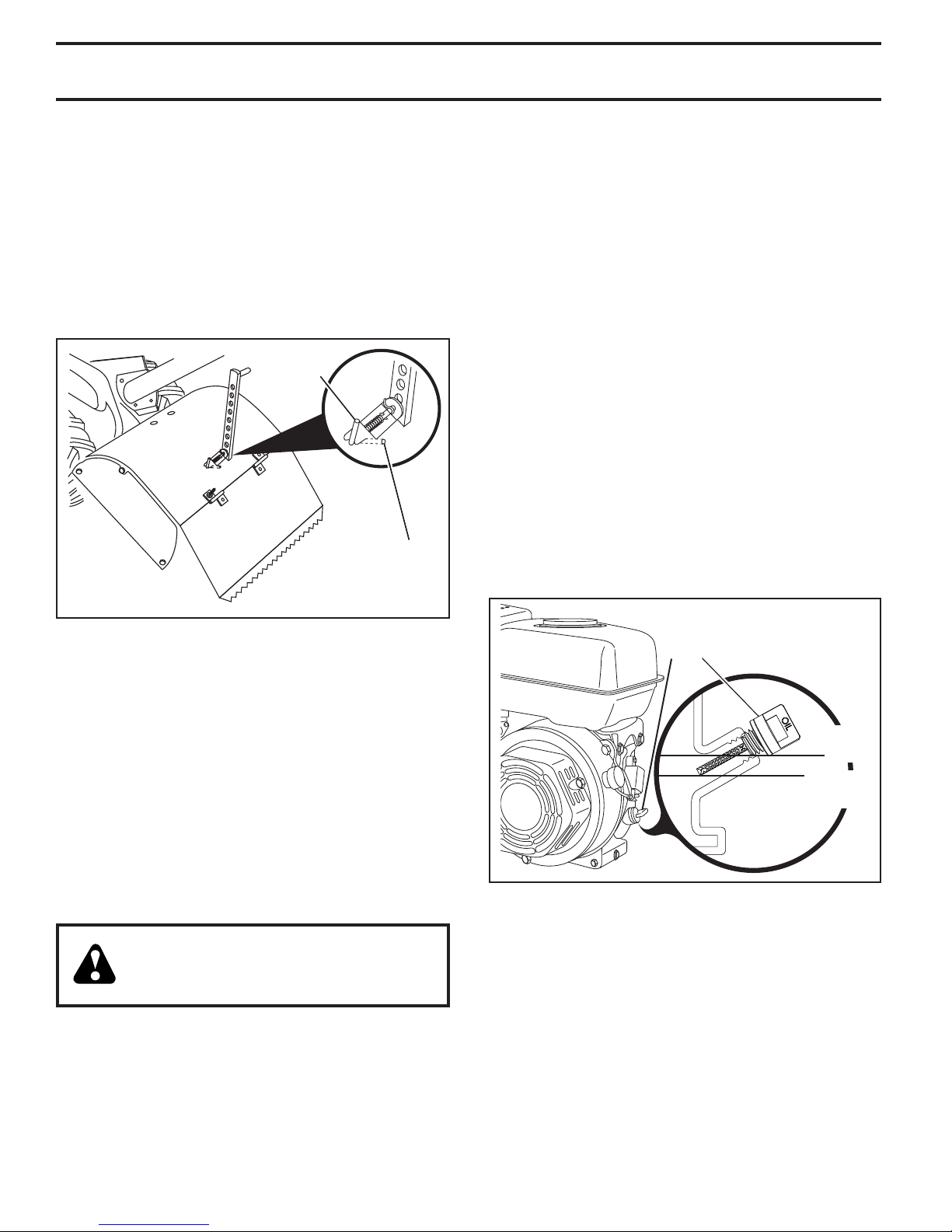
TILLING (See Fig. 11)
• Release depth stake pin. Pull the depth stake up for
increased tilling depth. Place depth stake pin in hole
of depth stake to lock in position.
• Place shift lever indicator in tilling position.
• Hold the drive control bar against the handle to start
tilling movement. Tines and wheels will both turn.
• Move throttle control to “FAST” position for deep tilling. To
cultivate, throttle control can be set at any desired speed,
depending on how fast or slow you wish to cultivate.
IMPORTANT: ALWAYS RELEASE DRIVE CONTROL BAR
BEFORE MOVING SHIFT LEVER INTO ANOTHER POSITION.
“RELEASED”
POSITION
DEPTH
STAKE PIN
“LOCKED”
POSITION
• Move throttle control to desired speed.
AROUND TOWN
• Disconnect spark plug wire.
• Drain fuel tank.
• Transport in upright position to prevent oil leakage.
BEFORE START ING ENGINE
IMPORTANT: BE VERY CAREFUL NOT TO ALLOW DIRT TO
ENTER THE ENGINE WHEN CHECKING OR ADDING OIL OR
FUEL. USE CLEAN OIL AND FUEL AND STORE IN AP PROVED,
CLEAN, COVERED CONTAINERS. USE CLEAN FILL FUNNELS.
CHECK ENGINE OIL LEVEL (See Fig. 12)
• The engine in your unit has been shipped, from the
factory, already filled with SAE 30 summer weight oil.
• With engine level, clean area around oil filler plug and
remove plug.
• Engine oil should be to point of overflowing when engine is level. For ap proxi mate capacity see “PROD UCT
SPEC I FI CA TIONS” in this manual. All oil must meet
A.P.I. Service Classification SF-SJ.
• For cold weather operation you should change oil for
easier starting (See “OIL VISCOSITY CHART” in the
Maintenance sec tion of this manual).
• To change engine oil, see the Maintenance section of
this manual.
Fig. 11
TURNING
• Release the drive control bar.
• Move throttle control to “SLOW” position.
• Place shift lever indicator in “F” (forward) position.
Tines will not turn.
• Lift handle to raise tines out of ground.
• Swing the handle in the opposite direction you wish to
turn, being careful to keep feet and legs away from tines.
• When you have completed your turn-around, release
the drive control bar and lower handle. Place shift
lever in till position and move throttle control to de sired
speed. To begin tilling, hold drive control bar against
the handle.
TO TRANSPORT
CAUTION: Before lifting or trans port ing, allow tiller engine and muffler to
cool. Disconnect spark plug wire. Drain
gasoline from fuel tank.
AROUND THE YARD
• Release the depth stake pin. Move the depth stake
down to the top hole for transporting the tiller. Place
depth stake pin in hole of depth stake to lock in position. This prevents tines from scuffing the ground.
• Place shift lever indicator in “F” (forward) position for
transporting.
• Hold the drive control bar against the handle to start
tiller movement. Tines will not turn.
OIL
FILLER
PLUG
MAXIMUM
UPPER
LEVEL
MINIMUM
UPPER
LEVEL
Fig. 12
10
OPERATION
ADD GASOLINE
• Fill fuel tank to bottom of filler neck. Do not overfill.
Use fresh, clean, regular un lead ed gasoline with a
minimum of 87 octane. Do not mix oil with gasoline.
Purchase fuel in quan ti ties that can be used within 30
days to assure fuel freshness.
CAUTION: Fill to within 1/2 inch of top
of fuel tank to prevent spills and to
allow for fuel expansion. If gasoline
is ac ci den tal ly spilled, move machine
away from area of spill. Avoid creating
any source of ignition until gasoline
vapors have disappeared.
Wipe off any spilled oil or fuel. Do not
store, spill or use gasoline near an
open flame.
IMPORTANT: WHEN OPERATING IN TEMPERATURES
BELOW32°F(0°C), USE FRESH, CLEAN WINTER GRADE
GAS O LINE TO HELP INSURE GOOD COLD WEATHER
START ING.
CAUTION: Alcohol blended fuels (called
gas o hol or using ethanol or methanol)
can attract moisture which leads to
sep a ra tion and for ma tion of acids during storage. Acidic gas can damage
the fuel system of an engine while in
storage. To avoid engine problems, the
fuel system should be emptied before
stor age of 30 days or longer. Drain
the gas tank, start the engine and let it
run until the fuel lines and carburetor
are empty. Use fresh fuel next sea son.
See Storage In struc tions for additional
information. Never use engine or carburetor cleaner products in the fuel
tank or permanent damage may occur.
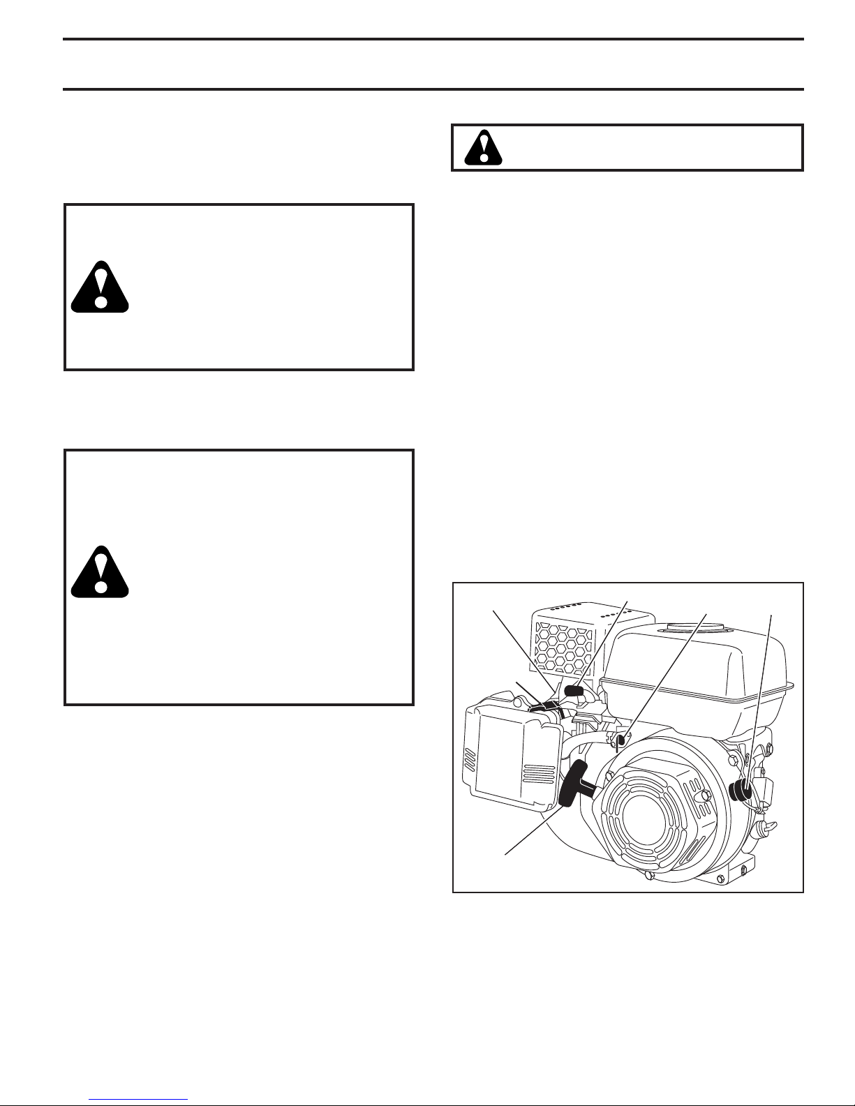
TO START ENGINE (See Fig. 13)
CAUTION: KEEP TINE CONTROL IN “OFF”
PO SI TION WHEN STARTING ENGINE.
When starting engine for the first time or if engine has run
out of fuel, it will take ex tra pulls of the recoil starter to
move fuel from the tank to the engine.
1. Make sure spark plug wire is prop er ly connected.
2. Place the fuel valve to the "ON" position.
3. To start a cold engine, move the choke lever to the
"ON" position.
4. Move the throttle lever away from the "SLOW" position,
about 1/3 of the way toward the "FAST" position.
5. Turn the engine switch to the "ON" position. Pull rope
out slowly until engine reaches start of com pres sion
cy cle (rope will pull slightly harder at this point).
6. Pull recoil starter handle quickly. Do not let starter
handle snap back against starter. Repeat if necessary.
NOTE: If engine fires but does not start, move choke control to
half choke position. Pull recoil starter handle until engine starts.
7. If the choke lever has been moved to the "ON" position
to start the engine, gradually move it to the opposite
position as the engine warms up.
NOTE: A warm engine requires less chok ing to start.
8. Move throttle control to desired running position.
9. Allow engine to warm up for a few min utes before
engaging tines.
NOTE: If engine does not start, see trou ble -shoot ing points.
SPARK
PLUG
CHOKE
CON TROL
THROTTLE CONTROL ENGINE
FUEL
VALVE
SWITCH
11
RECOIL
STARTER
HANDLE
Fig. 13
OPERATION
321
5
4
67
TILLING HINTS
CAUTION: Until you are accustomed to
handling your tiller, start actual field use
with throttle in slow position (mid-way
between “FAST” and “IDLE”).
• Tilling is digging into, turning over, and breaking up
packed soil before planting. Loose, unpacked soil
helps root growth. Best tilling depth is 4" to 6" (10-15
cm). A tiller will also clear the soil of unwanted vege ta tion. The de com po si tion of this vegetable mat ter
enriches the soil. Depending on the climate (rain fall
and wind), it may be advisable to till the soil at the end
of the growing season to further condition the soil.
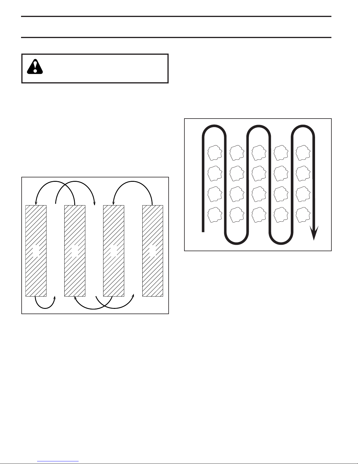
• You will find tilling much easier if you leave a row untilled between passes. Then go back between tilled
rows. (See Fig. 14) There are two reasons for doing
this. First, wide turns are much easier to negotiate than
about-faces. Sec ond, the tiller won’t be pulling itself,
and you, toward the row next to it.
CULTIVATING
Cultivating is destroying the weeds between rows to pre vent
them from robbing nourishment and moisture from the
plants. At the same time, breaking up the upper layer of
soil crust will help retain moisture in the soil. Best digging
depth is 1" to 3" (2.5-7.5 cm). Lower the outer side shields
to protect small plants from being buried.
• Cultivate up and down the rows at a speed which will
allow tines to uproot weeds and leave the ground in
rough condition, promoting no further growth of weeds
and grass (See Fig. 15).
Fig. 14
• Soil conditions are important for proper tilling. Tines will
not readily penetrate dry, hard soil which may con trib ute
to excessive bounce and difficult handling of your tiller.
Hard soil should be mois tened before tilling; however,
extremely wet soil will “ball-up” or clump during tilling.
Wait until the soil is less wet in order to achieve the
best results. When tilling in the fall, re move vines and
long grass to prevent them from wrapping around the
tine shaft and slowing your tilling operation.
• Do not lean on handle. This takes weight off the wheels
and reduces traction. To get through a really tough
section of sod or hard ground, apply upward pressure
on handle or lower the depth stake.
Fig. 15
TINE SHEAR PINS
The tine assemblies on your tiller are secured to the tine
shaft with shear pins (See “TINE REPLACEMENT” in the
Service and Ad just ments section of this manual).
If the tiller is unusually overloaded or jammed, the shear
pins are designed to break before internal damage occurs
to the trans mis sion.
• If shear pin(s) break, replace only with Original Equipment Manufacturer (O.E.M.) replacement parts.
12
 Loading...