

Poulan PPB300E Owner’s Manual

PoulanPRO /
• 1-800-554-6723
www.poulan-pro.com
Instruction Manual
Manual de Instrucciones
Manuel d'lnstructions
PPB3OOE /
For Occasional Use Only
DANGER:
Read and follow all Safety Rules and Operating Instructions before
using this product. Failure to do so can result in serious injury.
PELIGRO:
Lea el manual de instrucciones y siga todas las advertencias e
instrucciones de seguridad. El no hacerlo puede resultar en le-
siones graves.
DANGER:
Lire le manuel d'instructions et bien respecter tousles avertisse-
ments et toutes les instructions de s6curite. Tout defaut de le
faire pourrait entraTner des blessures graves.
Poulan PRO
1030 Stevens Creek Road
Augusta, GA 30907
545137275
11/30/06
A
all, WARNING: When using gardening
appliances, basic safety precautions must al-
ways be followed to reduce the risk of fire and
serious injury.
DANGER: Thispowertooleanbedan-
gerous! This unit can cause serious injury in-
cluding amputation or blindness to the operator
and others. The wamings and safety instruc-
tions in this manual must be followed to provide
reasonable safety and efficiency in using the
unit. The operator is responsible for following the
warnings and instructions in this manual and on
the unit. Read the entire instruction manual be-
fore assembling and using the unit! Restrict the
use of this unit to persons who read, under-
stand, and follow the warnings and instructions
in this manual and on the unit. Never aflow chiF
dren to operate this unit.
INSTRUCTION SAFETY INFORMATION
MANUAL ON THE UNIT
.-&
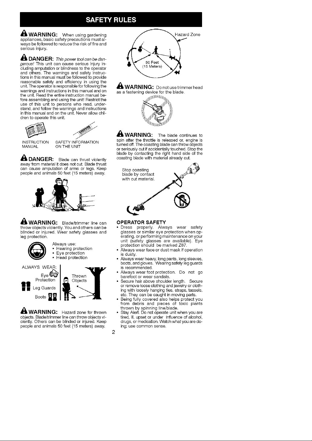
DANGER: Blade can thrust vioiently
away from material it does not cut, Blade thrust
can cause amputation of arms or legs, Keep
people and animals 50 feet (15 meters) away.
d Zone
A_&WARNING: Do not use trimmer head
as a fastening device for the blade.
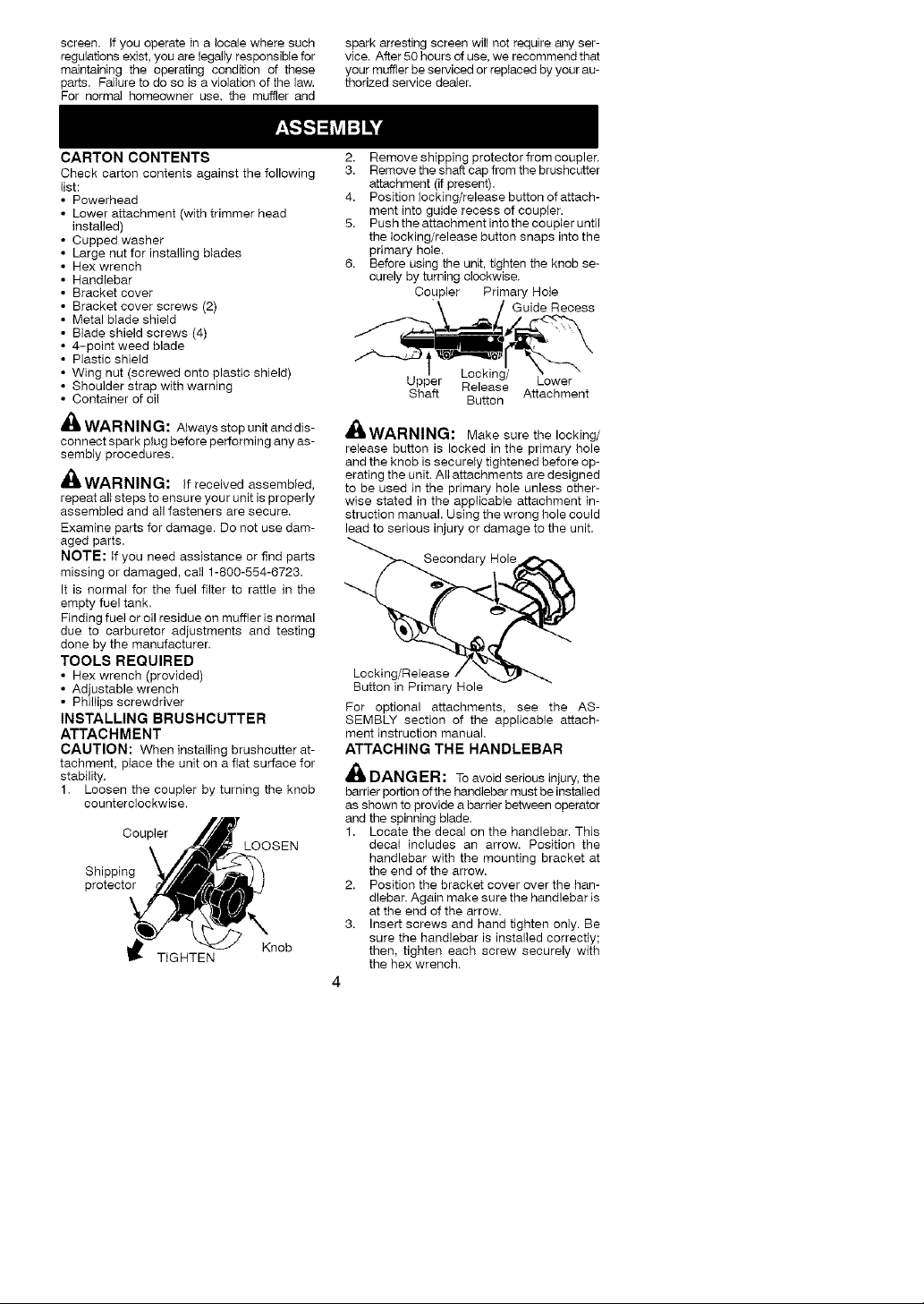
4nlIWAl-{l_lll_l_: The blade continues to
spin after the throttle is released or, engine is
turned off. The coasting blade can throw objects
or seriously cut if eocideotaIly touched. Stop the
blade by contacting the right hand side of the
coasting blade with material already cut,
bS_a°cPC_yStionrgact _
with cut material.._
A
dl_ WARNING: Blade/trimmer line can
throw objects vioiently, You and others can be
blinded or injured. Wear safety glasses and
leg protection.
Always use:
• Hearing protection
• Eye protection
• Head protection
ALWAYS WEAR:
Eye_
Protection
gill
• • Leg Guards
Boots _
_IWARNING: Hazard zone for thrown
objects. Blade/trimmer line can throw objects vi-
olently, Others can be blinded or injured, Keep
people and animals 50 feet (15 meters) away.
OPERATOR SAFETY
• Dress properly. A_ways wear safety
glasses or similar eye protection when op-
erating, or performing maintenance on your
unit (safety glasses are available). Eye
protection should be marked Z87.
• Always wear face or dust mask if operation
is dusty.
• Always wear heavy, long pants, tong sleeves,
boots, and gloves. Wearing safety leg guards
is recommended.
• Always wear foot protection. Do not go
barefoot or wear sandals.
• Secure hair above shoulder length. Secure
or remove loose clothing and jewelry or cloth-
ing with loosely hanging ties, straps, tassels,
etc. They can be caught in moving parts.
• Being fully covered also helps protect you
from debris and pieces of toxic plants
thrown by spinning line/blade.
• Stay Alert. Do not operate unit when you are
tired, ill, upset or under influence of alcohol,
drugs, or medication. Watch what you are do-
ing; use common sense.
2

• Wearhearingprotection.
• Neverstartorruntheengineinsidea
closedroomorbuilding.Breathingexhaust
fumescankill.
• Keephandlesfreeofoilandfuel.
• Alwaysusethehandlebarandaproperly
adjustedshoulderstrapwithablade(see
ASSEMBLY).
UNIT/MAINTENANCE SAFETY
,_ WARNING: Stopunitanddisoonnect
the spark plug before performing mainte-
nance (except carburetor adjustments),
• Look for and replace damaged or loose
parts before each use. Look for and repair
fuel leaks before use. Keep unit h_ good
working condition.
• Throw away blades that are bent, warped,
cracked, broken, or damaged in any other
way. Reptace trimmer head parts that are
cracked, chipped, broken, or damaged in
any other way before using the unit.
• Mah_tain unit accordh_g to recommended
procedures. Keep blade sharp, Keep cut-
flng line at the proper length,
• Use only Poulan PRO brand replacement
line. Never use wire, rope, string, etc.
• Install required shield properly before using
the unit, Use the metal shield for all metal
blade use. Use the plastic shield for all line
trimmer use.
• Use only specified blade or trimmer head;
make sure it is properly installed and se-
curely fastened.
• Never start engine with clutch shroud re-
moved. The clutch can fly off and cause se-
rious injury.
• Be sure blade or trimmer head stops turning
when engine idles.
• Make carburetor adjustments with the low-
er end supported to prevent blade or trim-
mer line from contacting any object. Hold
unit by hand; do not use the shoulder strap
for support.
• Keep others away when making carburetor
adjustments.
• Use only recommended Poulan PRO ac-
cessories and replacement parts.
• Have all maintenance and service not ex-
plained in this manual performed by your au-
thorized service dealen
FUEL SAFETY
• Mix and pour fuel outdoors.
• Keep away from sparks or flames.
• Use a container approved for fuel.
• Do not smoke or allow smoking near fuel or
the unit or while using the unit.
• Avoid spilling fuel or oil. Wipe up all fuel
spills before starting engine.
• Move at least 10 feet (3 meters) away from
fueling site before starting engine.
• Stop engine and allow it to cool before re-
moving fuel cap.
• Emptythe fueltank before storing or trans-
porting the unit. Use up fuel left in the car-
buretor by starting the engine and letting it
run until it stops.
• Store unit and fuel in area where fuel vapors
cannot reach sparks or open flames from
water heaters, electric motors or switches.
furnaces, etc.
• Always store gasoline in a container ap-
proved for flammable liquids.
CUTTING SAFETY
_WARNING: ti_spect the area to be
cut before each use. Remove objects (rocks,
broken glass, nails, wire, string, etc,) which
can be thrown or become entangled in the
blade or trimmer head.
• Keep others including children, animals.
bystanders, and helpers at least 50 feet (15
meters) away. Stop engine immediately if
you are approached.
• Always keep engine on the right-hand side
of your body.
• Hoid the unit firmly with both hands.
• Keep firm footing and balance. Do not over-
reach.
• Keep blade or trimmer head below waist
level. Do not raise engine above your waist.
• Keep all parts of your body away from
blade, trimmer head. and muffler when en-
gineis running. A hot muffler can cause se-
odus burns.
• Cut from your left to your right. Cutting on
right side of the shield will throw debris
away from the operator.
• Use only in daylight or good artificial light.
• Use only for jobs explained in this manual.
TRANSPORTING AND STORAGE
• Stop the unit before carrying.
• Keep muffler away from your body.
• Allow the engine to cool and secure the unit
before storing or transporting it in a vehicle.
• Empty the fuel tank before storing or trans-
porting the unit. Use upfuel left in the carbu-
retor by starting the engine and _etting it run
until it stops.
• Store unit so the blade or line limiter blade
cannot accidentally cause injury. The unit
can be hung by the shaft.
• Store unit out of reach of children.
SAFETY NOTICE: Exposure to vibrations
through prolonged use of gasoline powered
hand tools could cause blood vessel or nerve
damage in the fingers, hands, and joints of
people prone to circulation disorders or abnor-
mal swellings. Prolonged use in cold weather
has been linked to blood vessel damage in
otherwise healthy people. If symptoms occur
such as numbness, pain, toss of strength.
change in skin color or texture, or loss of feeling
in the fingers, hands, or joints, discontinue the
use of this tool and seek medical attention. An
anti-vibration system does not guarantee the
avoidance of these problems. Users who oper-
ate power tools on a continual and regular basis
must monitor closely their physical condition
and the condition of this tool.
SPECIAL NOTICE: This unit is equipped
with a temperature limiting muffler and spark ar-
resting screen which meets the requirements of
California Codes 4442 and 4443. All U.S. forest
land and the states of California. idaho. Maine.
Minnesota. New Jersey, Oregon, and Washing-
ton require by taw that many internal combus-
tion engines be equipped with a spark arresting
3
screen.Ifyouoperateinalocalewheresuch
regulationsexist,youarelegallyresponsiblefor
maintainingtheoperatingconditionofthese
parts.Failuretodosoisaviolationofthelaw.
Fornormalhomeowneruse,themufflerand
spark arresting screen wilt not require any ser-
vice. After 50 hours of use, we recommend that
your mLrffler be serviced or replaced by your au-
thorized service dealer.
CARTON CONTENTS
Check carton contents against the following
list:
• Powerhead
• Lower attachment (with trimmer head
installed)
Cupped washer
Large nut for installing blades
Hex wrench
Handlebar
Bracket cover
Bracket cover screws (2)
Metal blade shield
Blade shield screws (4)
4-point weed blade
Plastic shield
Wing nut (screwed onto plastic shield)
Shoulder strap with warning
Container of oil
WAR NIN G: Always stop unit and dis-
connect spark plug before performing any as-
sembly procedures.
_WARNING: If received assembled,
repeat all steps to ensure your unit is properly
assembled and all fasteners are secure.
Examine parts for damage. De net use dam-
aged parts.
NOTE: If you need assistance or find parts
missing or damaged, call 1-800-554-6723.
It is normal for the fuel filter to rattle in the
empty fuel tank.
Finding fuel or oil residue on muffler is normal
due to carburetor adjustments and testing
done by the manufacturer.
TOOLS REQUIRED
• Hex wrench (provided)
• Adjustable wrench
• Phillips screwdriver
INSTALLING BRUSHCUTTER
ATTACHMENT
CAUTION: When installing brushcutter at-
tachment, place the unit on a flat surface for
stability.
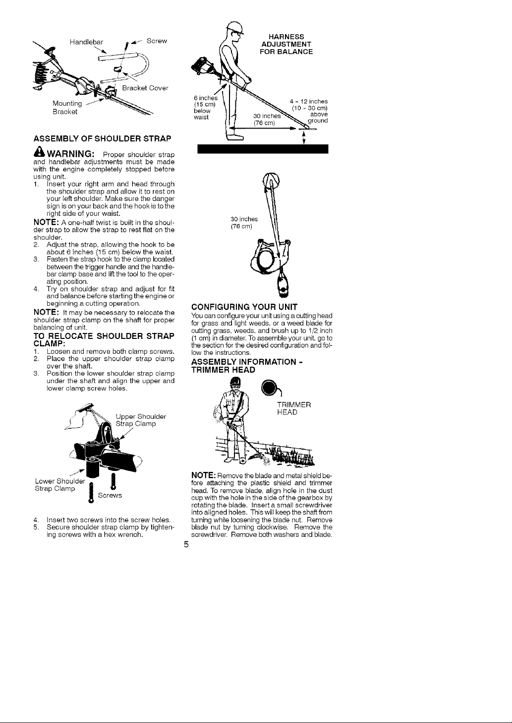
1. Loosen the coupler by turning the knob
counterclockwise.
Shipping
protector
Coupler
TIGHTEN
LOOSEN
Knob
2. Remove shipping protector from coupler,
3. Remove the shaft cap from the brushcutter
attachment (if present).
4. Position locking/release button of attach-
ment into guide recess of coupler.
5. Push the attachment intothe coupIer until
the locking/release button snaps into the
primary hole,
6. Before using the unit, tighten the knob se-
curely by turning clockwise,
Coupler Primary Hole
Upper Release Lower
Shaft Attachment
Guide Recess
Locking/
Button
w_WARNING: Make sure the locking/
release button is locked in the primary hole
and the knob is securely tightened before op-
erating the unit. All attachments are designed
to be used in the primary hole unless other-
wise stated in the applicable attachment in-
struction manual. Using the wrong hole could
lead to serious injury or damage to the unit.
Secondary Hole
Locking/Release
Button in Primary Hole
For optional attachments, see the AS-
SEMBLY section of the applicable attach-
ment instruction manual.
ATTACHING THE HANDLEBAR
DANGER: To avoid serious injury, the
barrier portion of the handlebar must be installed
as shown to provide a barrier between operator
and the spinning blade.
1. Locate the decal on the handlebar. This
decal includes an arrow. Position the
handlebar with the mounting bracket at
the end of the arrow.
2. Position the bracket cover over the han-
dlebar. Again make sure the handlebar is
at the end of the arrow.
3. Insert screws and hand tighten only. Be
sure the handlebar is installed correctly;
then, tighten each screw securely with
the hex wrench.
Handlebarit_ Screw
Bracket Cover
Mounting
Bracket
ASSEMBLY OF SHOULDER STRAP
_.WARNING: Proper shoulder strap
and handlebar adjustments must be made
with the engine completely stopped before
using unit.
1. Insert your right arm and head through
the shoulder strap and allow it to rest on
your teft shoulder. Make sure the danger
sign is on your back and the hook is to the
right side of your waist.
NOTE: A one-half twist is built in the shouF
der strap to allow the strap to rest flat on the
shoulder.
2. Adjust the strap, allowing the hook to be
about 6 inches (15 cm) below the waist.
3. Fasten the strap hook to the clamp located
between the trigger handle and the handle-
bar clamp base and liftthe tool to the oper-
ating position.
4. Try on shoulder strap and adjust for fit
and balance before starting the engine or
beginning a cutting operation.
NOTE: It may be necessary to relocate the
shoulder strap clamp on the shaft for proper
balancing of unit.
TO RELOCATE SHOULDER STRAP
CLAMP:
1. Loosen and remove both clamp screws.
2. Place the upper shoulder strap clamp
over the shaft.
3. Position the lower shoulder strap clamp
under the shaft and align the upper and
lower clamp screw holes.
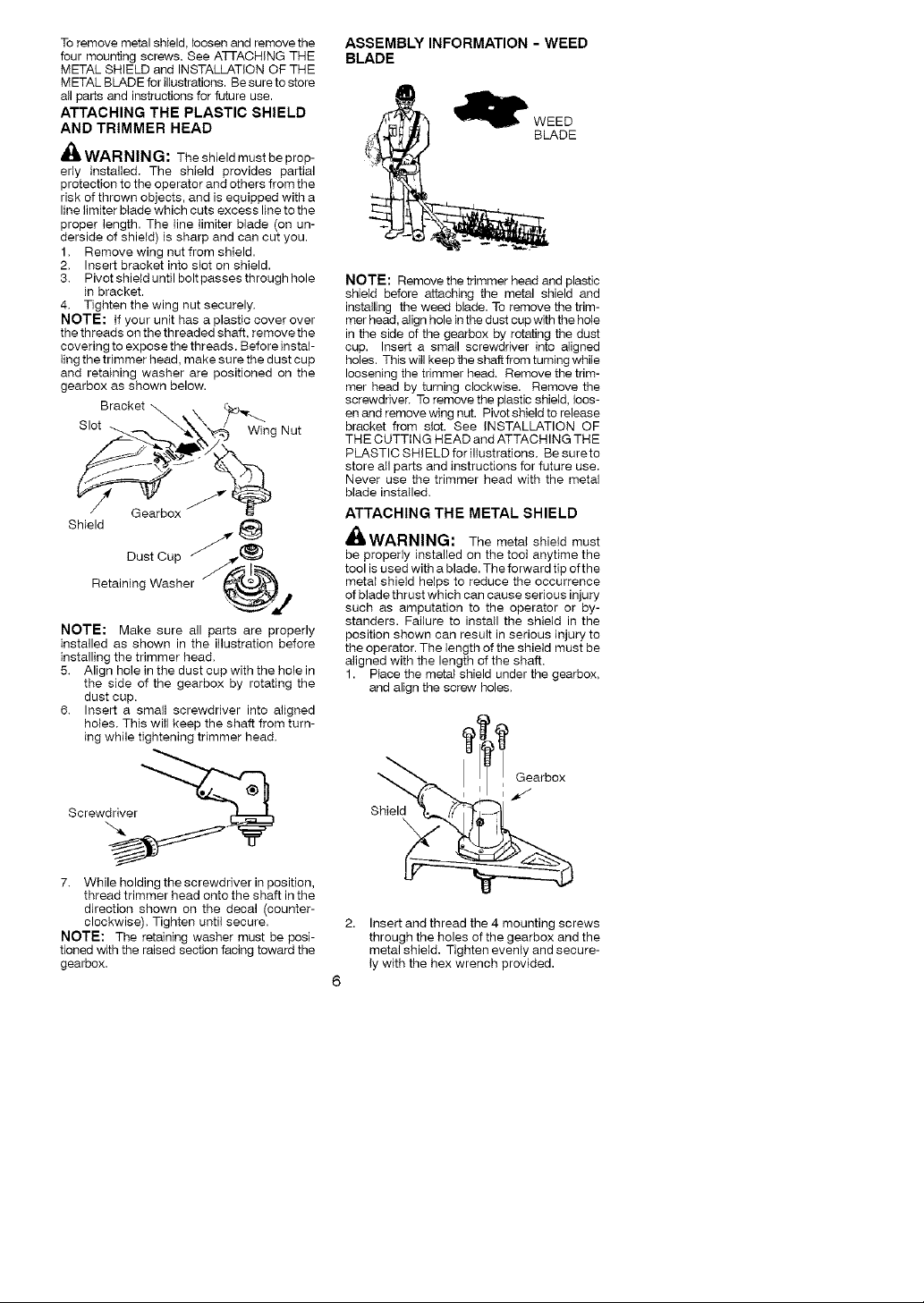
HARNESS
ADJUSTMENT
FOR BALANCE
(t5 cm) 4 - 12 inches
below _-_._ (10 - 30 cm)
waist 30 inches above
30 inches
(76 cm)
CONFIGURING YOUR UNIT
You can configure your unit using a cutting head
for grass and light weeds, or a weed blade for
cutting grass, weeds, and brush up to t/2 inch
(1 cm) in diameter. To assemble your unit, go to
the section for the desired configuration and fol-
low the instructions.
ASSEMBLY INFORMATION -
TRIMMER HEAD
:_._ TRIMMER
! Strap Clamp
Lower Shoulder J
Strap Clamp
4. Insert two screws into the screw holes.
5. Secure shoulder strap clamp by tighten-
ing screws with a hex wrench.
Screws
NOTE: Remove the blade and metal shield be-
fore attaching the plastic shield and trimmer
head. To remove blade, align hole in the dust
cup with the hole in the side of the gearbox by
rotating the blade. Insert a small screwdriver
into aligned holes. This will keep the shaft from
turning while loosening the blade nut. Remove
blade nut by turning clockwise. Remove the
screwdriver. Remove both washers and blade.
5
To remove metal shield, loosen and remove the
four mounting screws. See ATTACHING THE
METAL SHIELD and INSTALLATION OF THE
METAL BLADE for illustrations. Be sure to store
all parts and instructions for future use.
ATTACHING THE PLASTIC SHIELD
AND TRIMMER HEAD
_ WARNING: Theshieldmustbeprop-
erly installed. The shield provides partial
protection to the operator and others from the
risk of thrown objects, and is equipped with a
line limiter blade which cuts excess line to the
proper length. The line limiter blade (on un-
derside of shield) is sharp and can cut you.
1, Remove wing nut from shield.
2. Insert bracket into s_ot on shield.
3. Pivot shield until bolt passes through hole
in bracket.
4. Tighten the wing nut securely.
NOTE: If your unit has a plastic cover over
the threads on the threaded shaft, remove the
covering to expose the threads. Before instaF
ling the trimmer head, make sure the dust cup
and retaining washer are positioned on the
gearbox as shown below.
Bracket _
Slot Wing Nut
S
Gearbox
Shield
Ratai n_!_gtwCUs_ e__
NOTE: Make sure all parts are properly
installed as shown in the illustration before
installing the trimmer head.
5. Align hole in the dust cup with the hole in
the side of the gearbox by rotating the
dust cup.
6. Insert a smalt screwdriver into aligned
holes. This will keep the shaft from turn-
ing while tightening trimmer head.
ASSEMBLY INFORMATION - WEED
BLADE
NOTE: Remove the trimmer head and plastic
shield before attaching the metal shield and
installing the weed blade. To remove the trim-
mer head, align hole in the dust cup with the hole
in the side of the gearbox by rotating the dust
cup. Insert a small screwdriver into aligned
holes. This will keep the shaft from turning while
loosening the trimmer head, Remove the trim-
mer head by turning clockwise. Remove the
screwdriver, To remove the plastic shield, loos-
en and remove wing nut. Pivot shield to release
bracket from slot. See INSTALLATION OF
THE CUTTING HEAD and ATTACHING THE
PLASTIC SHIELD for illustrations. Be sureto
store all parts and instructions for future use.
Never use the trimmer head with the metal
blade installed.
ATTACHING THE METAL SHIELD
'_,WARNING: The metal shield must
be properly installed on the toot anytime the
tool is used with a blade. The forward tip ofthe
metal shield helps to reduce the occurrence
of blade thrust which can cause serious injury
such as amputation to the operator or by-
standers. Failure to install the shield in the
position shown can result in serious injury to
the operator. The length of the shield must be
aligned with the length of the shaft.
1. P_ace the metai shield under the gearbox,
and align the screw holes,
Screwdriver _
7. While holding the screwdriver in position,
thread trimmer head onto the shaft in the
direction shown on the decal (counter-
clockwise). Tighten until secure.
NOTE: The retaining washer must be posi-
tioned with the raised section facing toward the
gearbox.
, Gearbox
,_"
Shield
Insert and thread the 4 mounting screws
through the holes of the gearbox and the
metal shield. Tighten evenly and secure-
ly with the hex wrench provided.
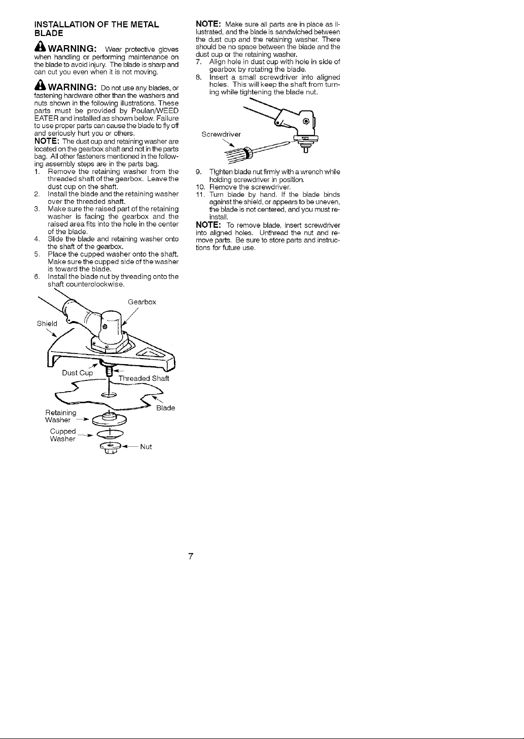
INSTALLATION OF THE METAL
BLADE
_WARNING: Wear protective gloves
when handling or performing maintenance on
the blade to avoid injury. The blade is sharp and
can cut you even when it is not moving.
WAR NIN G: Donot use any blades,or
fastening hardware other than the washers and
nuts shown in the following i_lustrations. These
parts must be provided by Poulan/WEED
EATER and installed as shown below. Failure
to use proper parts can cause the blade to fly off
and seriously hurt you or others.
NOTE: The dust cup and retaining washer are
located on the gearbox shaft and not in the parts
bag. All other fasteners mentioned in the follow-
ing assembty steps are in the parts bag.
1. Remove the retaining washer from the
threaded shaft of the gearbox. Leave the
dust cup on the shaft.
2. Install the blade and the retaining washer
over the threaded shaft.
3. Make sure the raised part of the retaining
washer is facing the gearbox and the
raised area fits into the hoie in the center
of the blade.
4. Slide the blade and retaining washer onto
the shaft of the gearbox.
5. Place the cupped washer onto the shaft.
Make sure the cupped side of the washer
is toward the blade.
6. Install the blade nut by threading onto the
shaft counterclockwise.
Gearbox
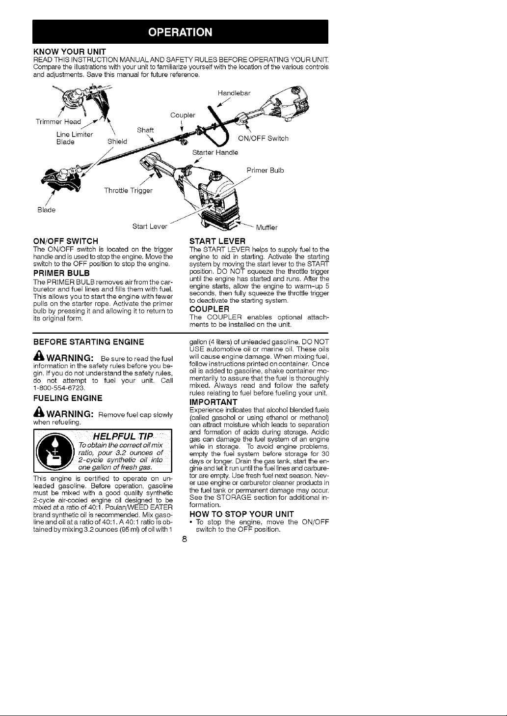
NOTE: Make sure all parts are in place as il-
lustrated, and the blade is sandwiched between
the dust cup and the retaining washer. There
should be no space between the blade and the
dust cup or the retaining washer.
7. Align hole in dust cup with hole in side of
gearbox by rotating the blade.
8. Insert a small screwdriver into aligned
hoies. This will keep the shaft from turn-
ing while tightening the blade nut.
Screwdriver _
9. Tighten blade nut firmly with a wrench while
holding screwdriver in position.
10. Remove the screwdriver.
11. Turn blade by hand. If the blade binds
against the shield, or appears to be uneven,
the blade is not centered, and you must re-
install.
NOTE: To remove blade, insert screwdriver
into aligned holes. Unthread the nut and re-
move parts. Be sure to store parts and instruc-
tions for future use.
Shield
Dust Cup
R_ade
etaining ___.,_
Washer _
Cupped
Washer
Threaded Shaft
_-"= Nut
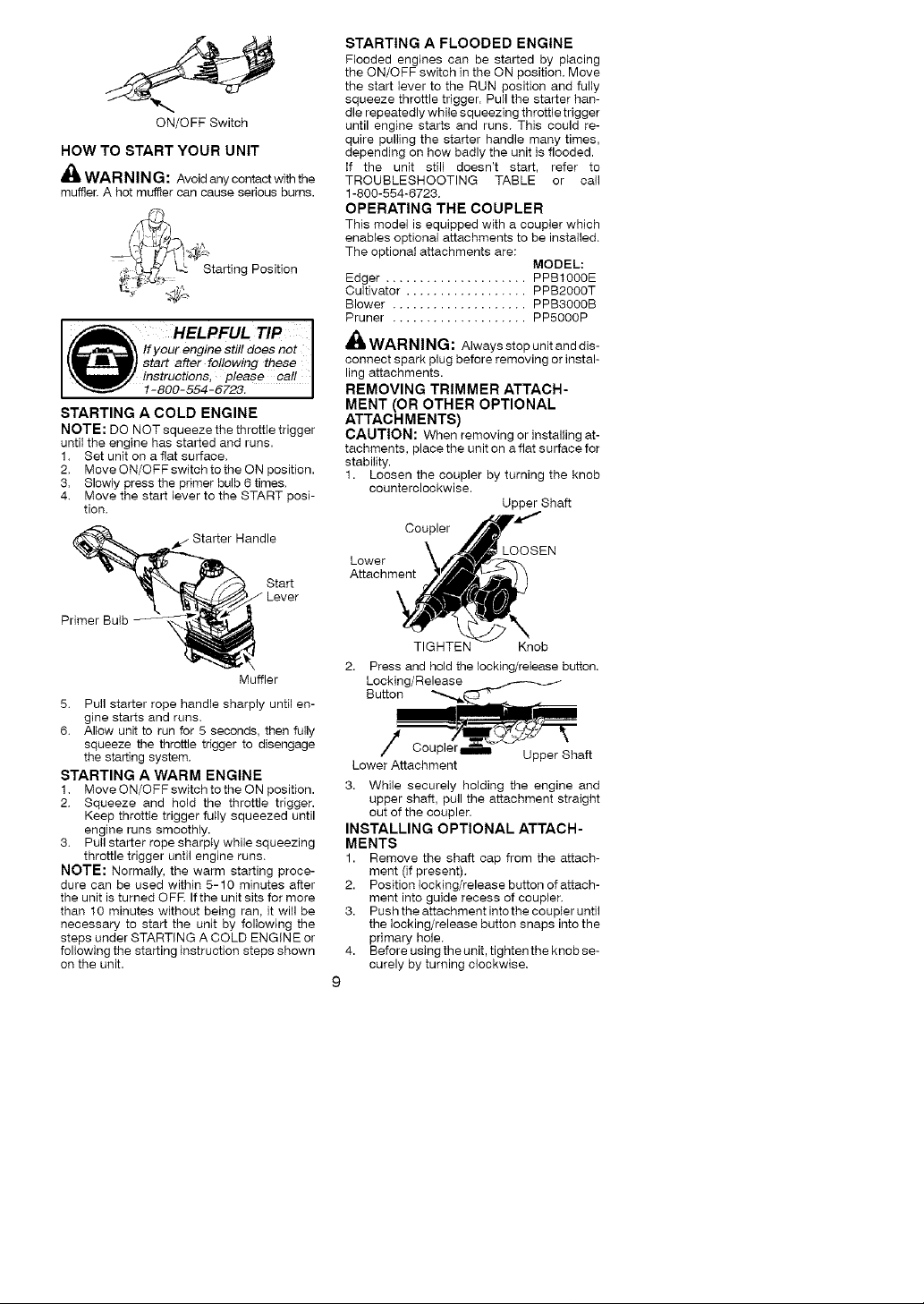
KNOW YOUR UNIT
READTHIS INSTRUCTION MANUALAND SAFETY RULESBEFORE OPERATINGYOUR UNIT
Compare the illustrations with your unit to familiarize yourself with the location of the various controls
and adjustments. Save this manual for future reference.
Handlebar
/
Trimmer Head/
Line Umiter
Blade Shield
Throttle Trigger
Blade
ON/OFF SWITCH
The ON/OFF switch is located on the trigger
handle and is used to stop the engine. Move the
switch to the OFF position to stop the engine.
PRIMER BULB
The PRIMER BULB removes air from the car-
buretor and fuel lines and fills them with fuel.
This allows you to start the engine with fewer
pulis on the starter rope. Activate the primer
bulb by pressing it and allowing it to return to
its original form.
Shaft
Start Lever
Coupler
ON/OFF Switch
Starter Handle
f
Primer Bulb
Muffler
START LEVER
The START LEVER helps to supply fuel to the
engine to aid in starting. Activate the starting
system by moving the start lever to the START
position. DO NOT squeeze the throttle trigger
until the engine has started and runs, After the
engine starts, allow the engine to warm-up 5
seconds, then fully squeeze the throttle trigger
to deactivate the starting system.
COUPLER
The COUPLER enables optional attach-
ments to be installed on the unit.
BEFORE STARTING ENGINE
_ WARNING: Be sure to read the fuel
information in the safety rules before you be-
gin. If you do not understand the safety rules,
do not attempt to fuel your unit. Call
1-800-554-6723,
FUELING ENGINE
_l_.WARNING: Remove fuel cap slowly
when refueling.
HELPFUL TIP
To obtain th e correct oil mix I
ratio, pour 3.2 ounces of
2-cycle synthetic oil into
one gallon of fresh gas.
This engine is certified to operate on un-
leaded gasoline, Before operation, gasoline
must be mixed with a good quality synthetic
2-cycle air-cooled engine oil designed to be
mixed at a ratio of 40:1. Poulan/WEED EATER
brand synthetic oil is recommended, Mix gaso-
line and oil at a ratio of 40:1, A 40:1 ratio is ob-
tained by mixing 3.2 ounces (95 ml) of oil with 1
gallon (4 liters) of unleaded gasoline. DO NOT
USE automotive oil or marine oil These oils
will cause engine damage, When mixing fuel,
follow instructions printed on container. Once
oil is added to gasoline, shake container mo-
mentarily to assure that the fuel is thoroughty
mixed, Always read and follow the safety
rules relating to fuel before fueling your unit.
IMPORTANT
Experience indicates that alcohol blended fuels
(called gasohol or using ethanol or methanol)
can attract moisture which leads to separation
and formation of acids during storage, Acidic
gas can damage the fuel system of an engine
while in storage. To avoid engine problems,
empty the fuel system before storage for 30
days or longer. Drain the gas tank, start the en-
gine and let it run until the fuel lines and carbure-
tor are empty, Use fresh fuel next season. Nev-
er use engine or carburetor cleaner products in
the fuel tank or permanent damage may occur.
See the STORAGE section for additional in-
formation.
HOW TO STOP YOUR UNIT
• To stop the engine, move the ON/OFF
switch to the OFF position,
8
ON/OFF Switch
HOW TO START YOUR UNIT
A(_WAR NIN G: Avoid any contact with the
muffler. A hot muffler can cause serious bums.
i_ _/ _ Starting Position
HELPFUL TIP I
!f yeur engine still does not
! start after following these
instructions, pleas e call
1-800-554-6723.
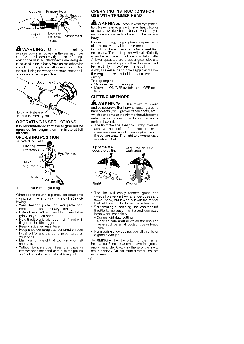
STARTING A COLD ENGINE
NOTE: DO NOT squeeze the throttle trigger
until the engine has started and runs.
1. Set unit on a flat surface.
2. Move ON/OFF switch to the ON position.
3. Slowly press the primer bulb 6 times.
4. Move the start lever to the START posi-
tion.
Handle
Start
STARTING A FLOODED ENGINE
Flooded engines can be started by p_acing
the ON/OFF switch in the ON position. Move
the start lever to the RUN position and fully
squeeze throttle trigger. Pull the starter han-
dle repeatedly while squeezing throttle trigger
until engine starts and runs. This could re-
quire pulling the starter handle many times,
depending on how badly the unit is flooded.
if the unit still doesn't start, refer to
TROUBLESHOOTING TABLE or call
1-800-554-6723.
OPERATING THE COUPLER
This model is equipped with a coupler which
enables optional attachments to be installed.
The optional attachments are:
Edger ..................... PPB1000E
Cultivator .................. PPB2000T
Blower .................... PPB3000B
Pruner .................... PP5000P
_ WARNING: Always stop unit and dis-
connect spark plug before removing or instal-
ling attachments.
REMOVING TRIMMER ATTACH-
MENT (OR OTHER OPTIONAL
ATTACHMENTS)
CAUTION: When removing or installing at-
tachments, place the unit on a flat surface for
stability.
1. Loosen the coupler by turning the knob
counterclockwise.
Coupler
Lower \
Attachment
MODEL:
Upper Shaft
LOOSEN
Primer Bulb
Muffler
5. Pull starter rope handle sharply until en-
gine starts and runs.
6. Allow unit to run for 5 seconds, then fully
squeeze the throttle trigger to disengage
the starting system.
STARTING A WARM ENGINE
1. Move ON/OFF switch to the ON position.
2. Squeeze and hold the throttle trigger.
Keep throttle trigger fully squeezed until
engine runs smoothly.
3. Pull starter rope sharply while squeezing
throttle trigger until engine runs.
NOTE: Normally, the warm starting proce-
dure can be used within 5-10 minutes after
the unit is turned OFR If the unit sits for more
than 10 minutes without being ran, it will be
necessary to start the unit by following the
steps under STARTING A COLD ENGINE or
following the starting instruction steps shown
on the unit.
TIGHTEN Knob
Press and hold the locking/re,ease button.
Locking/Release
Button
Lower Attachment
3. While securely holding the engine and
upper shaft, pull the attachment straight
out of the coupler.
INSTALLING OPTIONAL ATTACH-
MENTS
1. Remove the shaft cap from the attach-
merit (if present).
2. Position locking/release button of attach-
ment into guide recess of coupler.
3. Push the attachment into the coupler until
the locking/release button snaps into the
primary hole.
4. Before using the unit, tighten the knob se-
curely by turning clockwise.
9
CouplerPrimaryHole
Upper Locking/
Shaft ReleaseAttachment
'GuideRecess
Button
m_WARNING: Make sure the locking/
release button is locked in the primary hole
and the knob is securely tightened before op-
erating the unit. All attachments are designed
to be used in the primary hoIe unless otherwise
stated in the applicable attachment instruction
manual. Using the wrong hole could lead to seri-
ous injury or damage to the unit.
Secondary Hole
Locking/Release
Button in Primary Hole
OPERATING INSTRUCTIONS
It is recommended that the engine not be
operated for longer than 1 minute at full
throttle.
OPERATING POSITION
ALWAYS WEAR:
Hearing _
Protection
Heavy.
Long Pants
Eye Protection
OPERATING INSTRUCTIONS FOR
USE WITH TRIMMER HEAD
WARNING: Alwaysweareye protec-
tion,Never lean over the trimmer head. Rocks
or debris can ricochet or be thrown into eyes
and face and cause blindness or other serious
injury.
Before trimming, bring engine to e speed suffi-
cient to cut material to be trimmed.
Do not run the engine at a higher speed than
necessary. The cutting line will cut efficiently
when the engine is run at less than full throttle.
At lower speeds, there is less engine noise and
vibration. The cutting line will last longer and will
be less likely to "weld" onto the spool.
Always release the throttle trigger and allow
the engine to return to idle speed when not
cutting.
To stop engine:
• Release the throttle trigger.
• Move the ON/OFF switch to the OFF posi-
tion.
CUTTING METHODS
_,WARNING: use minimum speed
and do not crowd the line when cutting around
hard objects (rock, graveI, fence posts, etc,),
which can damage the trimmer head, become
entangled in the line, or be thrown causing a
serious hazard.
• The tip of the line does the cutting. You will
achieve the best performance and mini-
mum line wear by not crowding the line into
the cutting area, The right and wrong ways
are shown below.
Tip of the line
does the cutting.
Line crowded into
work area.
Cut from your left to your right.
When operating unit, clip shoulder strap onto
clamp, stand as shown and check for the fol-
lowing:
• Wear hearing protection, eye protection,
head protection and heavy clothing.
• Extend your left arm and hold handlebar
grip with your left hand.
• Hold throttle grip with your right hand with
finger on throttIe trigger.
• Keep unit below waist level.
• Keep shoulder strap pad centered on your
left shoulder and danger sign centered on
your back.
• Maintain full weight of tool on your left
shoulder.
• Without bending over, keep the blade or
trimmer head near and parallel to the ground
and not crowded into material being cut.
Right
• The line will easily remove grass and
weeds from around walls, fences, trees and
flower beds. but it also can cut the tender
bark of trees or shrubs and scar fences.
• Per trimming or scalping, use less than full
throttle to increase line life and decrease
head wear, especially:
• During light duty cutting.
• Near objects around which the line can
wrap such as small posts, trees or fence
wire.
• Pormowingorsweeping. usefullthrotttefor
a good clean job.
TRIMMING - Hold the bottom of the trimmer
head about 3 inches (8 cm) above the ground
and at an angle. Allow only the tip of the line to
make contact. Do not force trimmer line into
work area.
10
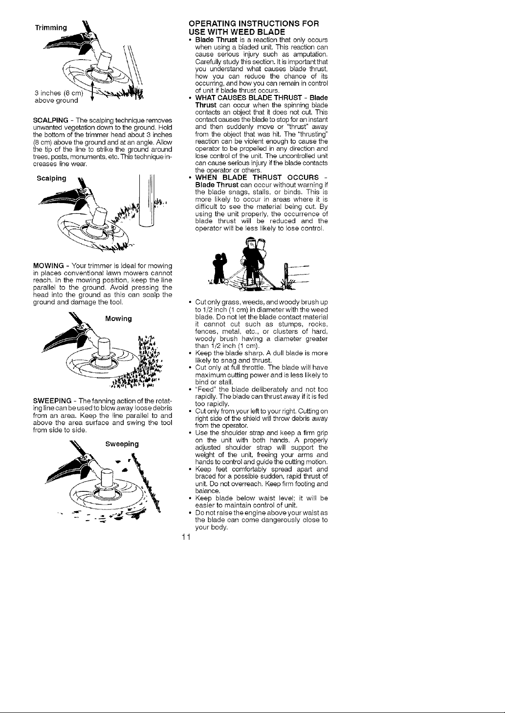
Trimming
3 inches (8 cm
above ground
SCALPING - The scalping technique removes
unwanted vegetation down to the ground. Hold
the bottom of the trimmer head about 3 inches
(8 cm) above the ground and at an angle. Allow
the tip of the line to strike the ground around
trees, posts, monuments, etc. This technique in-
creases line wear.
Scalping
MOWING - Your trimmer is ideal for mowing
in places conventional lawn mowers cannot
reach, in the mowing position, keep the line
parallel to the ground. Avoid pressing the
head into the ground as this can scalp the
ground and damage the tool.
/._ Mowing
SWEEPING - The fanning action of the rotat-
ing line can be used to blow away loose debris
from an area. Keep the line paratlel to and
above the area surface and swing the tool
from side to side.
OPERATING INSTRUCTIONS FOR
USE WITH WEED BLADE
• Blade Thrust is a reaction that only occurs
when using a b_aded unit. This reaction can
cause serious injury such as amputation.
Carefully study this section= it is important that
you understand what causes blade thrust,
how you can reduce the chance of its
occurring, and how you can remain in control
of unit if blade thrust occurs.
• WHAT CAUSES BLADE THRUST - Blade
Thrust can occur when the spinning blade
contacts an object that it does not cut. This
contact causes the blade to stop for an instant
and then suddenly move or "thrust" away
from the object that was hit. The "thrusting"
reaction can be violent enough to cause the
operator to be propelled in any direction and
lose control of the unit. The uncontrolled unit
can cause serious injury ifthe blade contacts
the operator or others.
• WHEN BLADE THRUST OCCURS -
Blade Thrust can occur without warning if
the blade snags, stalls, or binds. This is
more likely to occur in areas where it is
difficult to see the material being cut. By
using the unit properly, the occurrence of
blade thrust will be reduced and the
operator will be less likely to lose control.
• Cut only grass, weeds, and woody brush up
to 1/2 inch (1 cm) in diameter with the weed
blade. Do not let the blade contact material
it cannot cut such as stumps, rocks,
fences, metal, etc., or clusters of hard,
woody brush having a diameter greater
than 1/2 inch (t sin).
• Keep the blade sharp. A dull blade is more
likely to snag and thrust.
• Cut only at full throttle. The blade will have
maximum cutting power and is less likely to
bind or stall.
• "Feed" the blade deliberately and not too
rapidly. The blade can thrust away if it is fed
too rapidly.
• Cut only from your left to your right. Cutting on
right side of the shield will throw debris away
from the operator.
• Use the shoulder strap and keep a firm grip
on the unit with both hands. A properly
adjusted shoulder strap will support the
weight of the unit, freeing your arms and
hands to control and guide the cutting motion.
• Keep feet comfortably spread apart and
braced for a possible sudden, rapid thrust of
unit. Do not overreach. Keep firm footing and
balance.
• Keep blade below waist level; it will be
easier to maintain control of unit.
• Do not raise the engine above your waist as
the blade can come dangerously close to
your body.
1
• Do not swing unit with such force that you
are in danger of losing your balance.
Bring the engine to cutting speed before enter-
ing the material to be cut.if the blade does not
turn when you squeeze the throttle trigger, make
sure shaft is fully inserted into the engine.
Always release the throttle trigger and allow
engine to return to idle speed when not cut-
ting. The blade should not turn while the en-
gine is running at idle. Ifthe blade turns at idle,
do not use your unit. Refer to the OARBU RE-
TOR ADJUSTMENT section or contact your
authorized service dealer.
• Maintain good firm footing while using the
unit. Do this by planting feet firmly in a
comfortable apart position.
• Out while swinging the upper part of your
body from left to right.
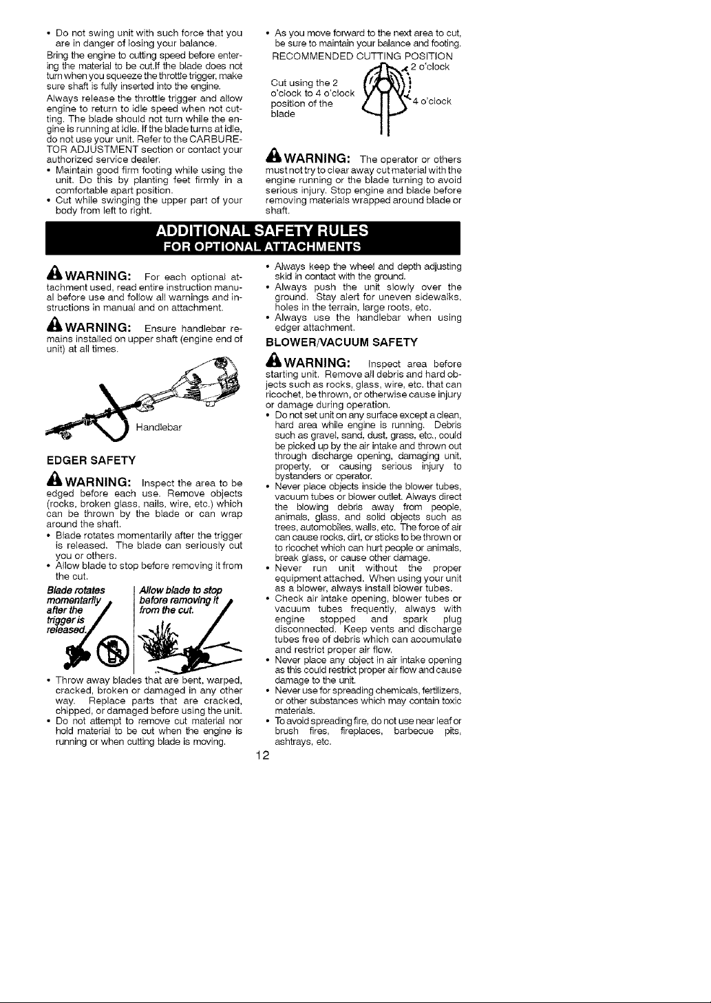
• As you move forward to the next area to cut,
be sure to maintain your balance and footing.
RECOMMENDED CUTTING POSITION
Cut using the 2 ...,,f"!_.(,_,_..}2
o'clock to 4 o'clock
position of the _ _ _ _'€4 o'clock
blade
V"l._ V¢
o'clock
"IF"
wmWARNING: The operator or others
must not try to clear away cut material with the
engine running or the blade turning to avoid
serious injury. Stop engine and blade before
removh_g materials wrapped around blade or
shaft.
,tA
rmWARNING: For each optional at-
tachment used, read entire instruction manu-
al before use and follow all warnings and in-
structions in manual and on attachment.
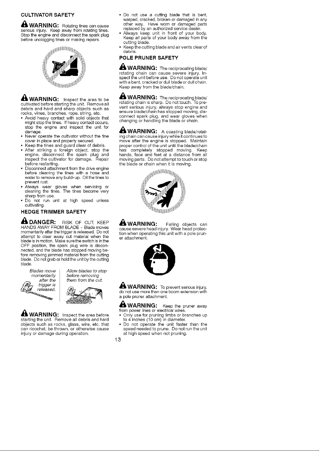
_WARNING: Ensure handlebar re-
mains installed on upper shaft (engine end of
unit) at all times.
Handlebar
EDGER SAFETY
WARNING: Inspect the area to be
edged before each use. Remove objects
(rocks, broken glass, nails, wire, etc,) which
can be thrown by the blade or can wrap
around the shaft.
• Blade rotates momentarily after the trigger
is released, The blade can seriously cut
you or others.
• Allow blade to stop before removing it from
the cut.
Blade rotates Allow blade to stop
after the from the cut.
trde_egeris
ased.
• Throw away blades that are bent, warped,
cracked, broken or damaged in any other
way. Replace parts that are cracked,
chipped, or damaged before using the unit.
• Do not attempt to remove cut material nor
hold material to be cut when the engine is
running or when cutting blade is moving.
before removing It
• Always keep the wheel and depth adjusting
skid in contact with the ground.
• Always push the unit slowly over the
ground. Stay alert for uneven sidewalks,
holes in the terrain, large roots, etc.
• Always use the handlebar when using
edger attachment.
BLOWER/VACUUM SAFETY
_;_,WARNING: Inspect area before
starting unit. Removealldebris and hard ob-
jects such as rocks, glass, wire, etc. that can
ricochet, be thrown, or otherwise cause injury
or damage during operation.
• Do not set unit on any surfece except a clean,
hard area while engine is running. Debris
such as gravel, sand, dust, grass, etc., could
be picked up by the air intake and thrown out
through discharge opening, damaging unit,
property, or causing serious injury to
bystanders or operator.
• Never place objects inside the blower tubes,
vacuum tubes or blower outlet. Always direct
the blowing debris away from peopIe,
animals, glass, and solid objects such as
trees, automobiles, walls, etc. The force of air
can cause rocks, dirt, or sticks to be thrown or
to ricochet which can hurt people or animals,
break glass, or cause other damage.
• Never run unit without the proper
equipment attached. When using your unit
as a blower, always install blower tubes.
• Check air intake opening, blower tubes or
vacuum tubes frequently, always with
engine stopped and spark plug
disconnected. Keep vents and discharge
tubes free of debris which can accumulate
and restrict proper air flow.
• Never place any object in air intake opening
as this could restrict proper air flow and cause
damage to the unit.
• Never use for spreading chemicals, fertilizers,
or other substances which may contain toxic
materials.
• Toavoidspreading fire, donot usenearleafor
brush fires, fireplaces, barbecue pits,
ashtrays, etc.
12
CULTIVATOR SAFETY
_, WARNING: Rotating tines can cause
serious injury. Keep away from rotating tines.
Stop the engine and disconnect the spark plug
before unclogging tines or making repairs.
A
WARNING: Inspect the area to be
cultivated before starting the unit. Removeall
debris and hard and sharp objects such as
rocks, vines, branches, rope, string, etc.
• Avoid heavy contact with solid objects that
might stop the tines. If heavy contact occurs,
stop the engine and inspect the unit for
damage.
• Never operate the cultivator without the tine
cover in place and properly secured.
• Keep the tines and guard clear of debris.
• After striking a foreign object, stop the
engh_e, disconnect the spark plug and
inspect the cultivator for damage. Repair
before restarting.
• Disconnect attachment from the drive engine
before cleaning the tines with a hose and
water to remove any build-up. Oil the tines to
prevent rust.
• Always wear gloves when servicing or
cleaning the tines. The tines become very
sharp from use.
• Do not run unit at high speed unless
cultivating.
HEDGE TRIMMER SAFETY
_DANGER: RISK OF CUT; KEEP
HANDS AWAY FROM BLADE - Blade moves
momentarily after thetrigger is released. Donot
attempt to clear away cut material when the
blade is in motion. Make sure the switch is in the
OFF position, the spark plug wire is discon-
nected, and the blade has stopped moving be-
fore removing jammed material from the cutting
blade. Do not grab or hold the unit by the cutting
blade.
Blades move
momentadly
after the
el_dtriggeris
Allow blades to stop
before removing
them from the cut.
_l_ WARNING: Inspecttheareabefore
starting the unit. Remove all debris and hard
objects such as rocks, glass, wire, etc. that
can ricochet, be thrown, or otherwise cause
injury or damage during operation.
• Do not use a cutting blade that is bent,
warped, cracked, broken or damaged in any
other way. Have worn or damaged parts
replaced by an authorized service dealer.
• Always keep unit in front of your body.
Keep all parts of your body away from the
cutting blade.
• Keep the cutting blade and air vents clear of
debris,
POLE PRUNER SAFETY
_, WARNING: The reciprocating blade/
rotating chain can cause severe injury. In-
spect the unit before use. Do not operate unit
with a bent, cracked or duff blade or dull chain.
Keep away from the blade/chain.
WARNING: The reciprocatingblade/
rotating chain is sharp. Do not touch. To pre-
vent serious injury, always stop engine and
ensure blade/chain has stopped moving, dis-
connect spark plug, and wear gloves when
changing or handling the blade or chain,
_WARNING: A coasting blade/rotat-
ing chain can cause injury while itcontinues to
move after the engine is stopped, Maintain
proper control of the unit until the Made/chain
has completely stopped moving, Keep
hands, face and feet at a distance from aft
moving parts. Do not attempt to touch or stop
the blade or chain when it is moving.
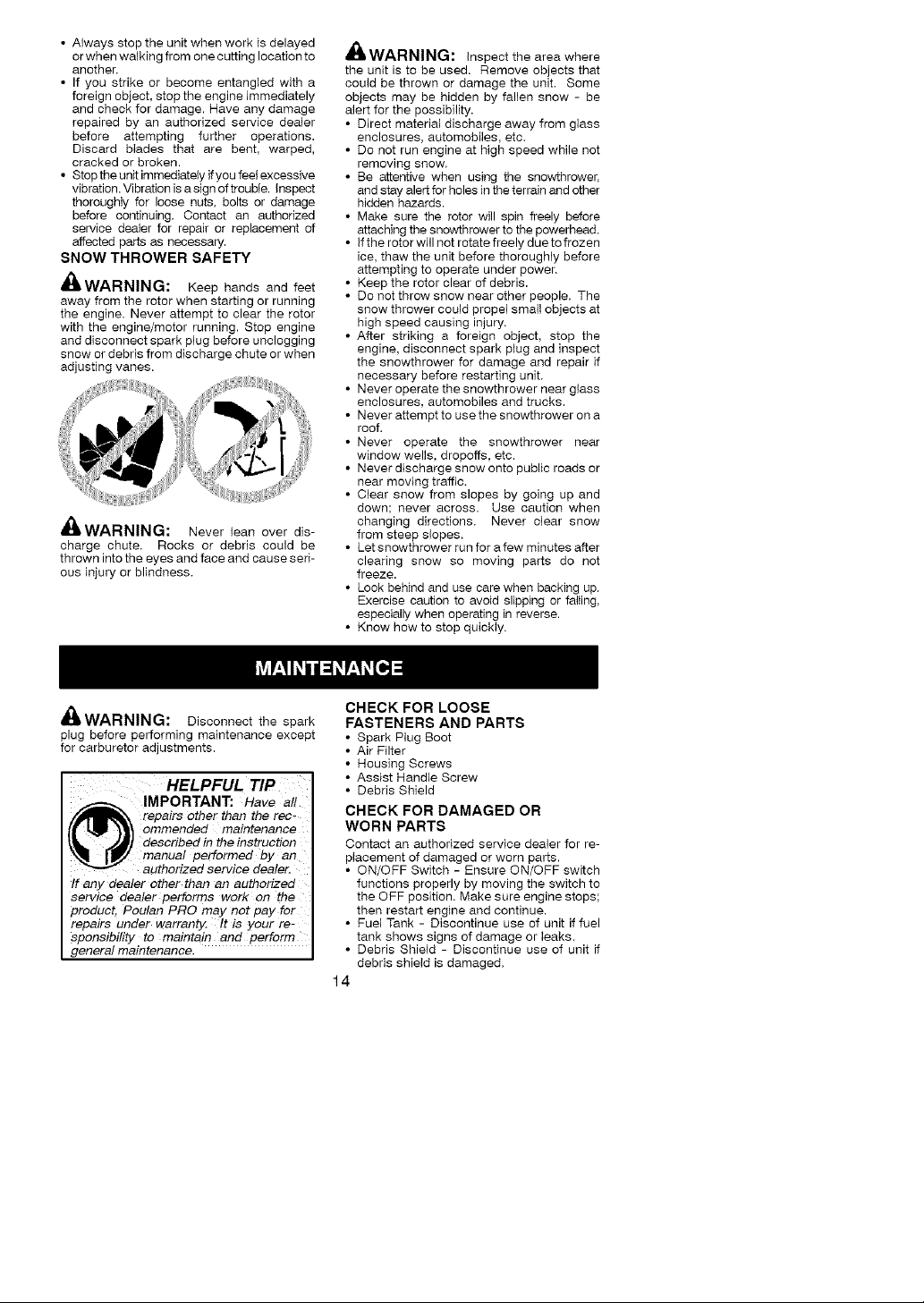
m_WARNING: Falling objects can
cause severe head injury. Wear head protec-
tion when operating this unit with a pole prun-
er attachment.
z't
_I= WARNING: Topreventserious injury,
do not use more than one boom extension with
a pole pruner attachment.
_b, WARNING: Keep the pruner away
from power fines or electrical wires.
• Only use for pruning limbs or branches up
to 4 inches (10 cm) in diameter.
• Do not operate the unit faster than the
speed needed to prune. Do not run the unit
at high speed when not pruning.
13
• Always stop the unit when work is delayed
or when walking from one cutting location to
another.
• If you strike or become entangled with a
foreign object, stop the engine immediately
and check for damage. Have any damage
repaired by an authorized service dealer
before attempting further operations.
Discard blades that are bent, warped,
cracked or broken.
• Stop the unit immediately ifyou feel excessive
vibration. Vibration isa sign of trouble, inspect
thoroughly for loose nuts, bolts or damage
before continuing. Contact an authorized
service dealer for repair or replacement of
affected parts as necessary.
SNOW THROWER SAFETY
_WARNING: Keep hands and feet
away from the rotor when starting or running
the engine. Never attempt to clear the rotor
with the engine/motor running. Stop engine
and disconnect spark plug before unclogging
snow or debris from discharge chute or when
adjusting vanes.
,_WARNING:
charge chute. Rocks or debris could be
thrown into the eyes and face and cause seri-
ous injury or blindness.
Never lean over dis-
•nWARNING: Inspect the area where
the unit is to be used. Remove objects that
could be thrown or damage the unit. Some
objects may be hidden by fallen snow - be
alert for the possibility.
• Direct material discharge away from glass
enclosures, automobiles, etc.
• Do not run engine at high speed while not
removh_g snow,
• Be attentive when using the snowthrower,
and stay alert for holes in the terrain and other
hidden hazards.
• Make sure the rotor will spin freely before
attaching the snowthrower to the powerhead,
• if the rotor will not rotate freely due to frozen
ice, thaw the unit before thoroughly before
attempting to operate under power,
• Keep the rotor clear of debris.
• Do not throw snow near other people, The
snow thrower could propel small objects at
high speed causing injury,
• After striking a foreign object, stop the
engine, disconnect spark plug and inspect
the snowthrower for damage and repair if
necessary before restarting unit,
• Never operate the snowthrower near gtass
enclosures, automobiles and trucks.
• Never attempt to use the snowthrower on a
roof.
• Never operate the snowthrower near
window wells, dropoffs, etc.
• Never discharge snow onto public roads or
near moving traffic,
• Clear snow from slopes by going up and
down; never across. Use caution when
changing directions, Never clear snow
from steep slopes,
• Let snowthrower run for a few minutes after
clearing snow so moving parts do not
freeze.
• Look behind and use care when backing up,
Exercise caution to avoid slipping or falling,
especially when operating in reverse.
• Know how to stop quickly.
,"=WARNING: Disconnect the spark
plug before performing maintenance except
for carburetor adjustments.
HELPFUL TIP
IMPORTANT: Have all
repairs Other than the rec-
ommended maintenance
described in the instruction
_nanual performed by an
If any dealer other than an authorized
service dealer performs work on the
product, Poalan PRO may not pay for
repairs under warranty. It is your re-
sponsibility to maintain and perform
general maintenance.
authorized service dealer.
CHECK FOR LOOSE
FASTENERS AND PARTS
• Spark Plug Boot
• Air Filter
• Housing Screws
• Assist Handle Screw
• Debris Shield
CHECK FOR DAMAGED OR
WORN PARTS
Contact an authorized service dealer for re-
pIacement of damaged or worn parts.
• ON/OFF Switch - Ensure ON/OFF switch
functions properly by moving the switch to
the OFF position, Make sure engine stops;
then restart engine and continue.
• Fuel Tank - Discontinue use of unit if fuel
tank shows signs of damage or leaks.
• Debris Shield - Discontinue use of unit if
debris shield is damaged,
14
INSPECT AND CLEAN UNIT AND DE-
CALS
• After each use. inspect compIete unit for
loose or damaged parts. Clean the unit and
decals using a damp cloth with a mild deter-
gent.
• Wipe off unit with a clean dry cloth.
CLEAN AIR FILTER
A dirty air filter decreases engine perform-
ance and increases fuel consumption and
harmful emissions. Always clean after every
5 hours of operation.
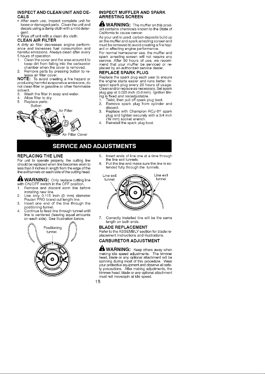
1. Clean the cover and the area around it to
keep dirt from falling into the carburetor
chamber when the cover is removed.
2. Remove parts by pressing button to re-
lease air filter cover.
NOTE: To avoid creating a fire hazard or
producing harmful evaporative emissions, do
not clean filter in gasoline or other flammable
soivent.
3. Wash the filter in soap and water.
4. Allow filter to dry.
5. Replace parts.
Button
Air Filter
Air Filter Cover
INSPECT MUFFLER AND SPARK
ARRESTING SCREEN
,_ WARNING: The muffler on this prod-
uct contains chemicals known to the State of
California to cause cancer.
As your unit is used, carbon deposits build up
on the muffler and spark arresting screen and
must be removed to avoid creating a fire haz-
ard or affecting engine performance.
For normal homeowner use, the muffler and
spark arresting screen will not require any
service. After 50 hours of use. we recom-
mend that your muffler be serviced or re-
placed by an authorized service dealer.
REPLACE SPARK PLUG
Replace the spark plug each year to ensure
the engine starts easier and runs better, in-
spect spark plug every 25 hours of usage.
Clean and/or replace as necessary. Set spark
plug gap at 0.025 inch (0.6 mm). Ignition tim-
ing is fixed and nonadjustable.
1. Twist, then pull off spark plug boot.
2. Remove spark plug from cylinder and
discard.
3. Replace with Champion RCJ-6Y spark
plug and tighten securely with a 3/4 inch
(19 mm) socket wrench.
4. Reinstall the spark plug boot.
REPLACING THE LINE
For unit to operate properly, the cutting line
should be replaced when line becomes worn to
less than 3 inches in length from the edge of the
line exit tunnels on each side ofthe cutting head.
_L. WARNING: Onlyreplacecuttingline
with ON/OFF switch in the OFF position.
1. Remove and discard worn line before
installing new line.
2. Use only 0.115 inch (3 mm) diameter
Poulan PRO brand cut length Hne.
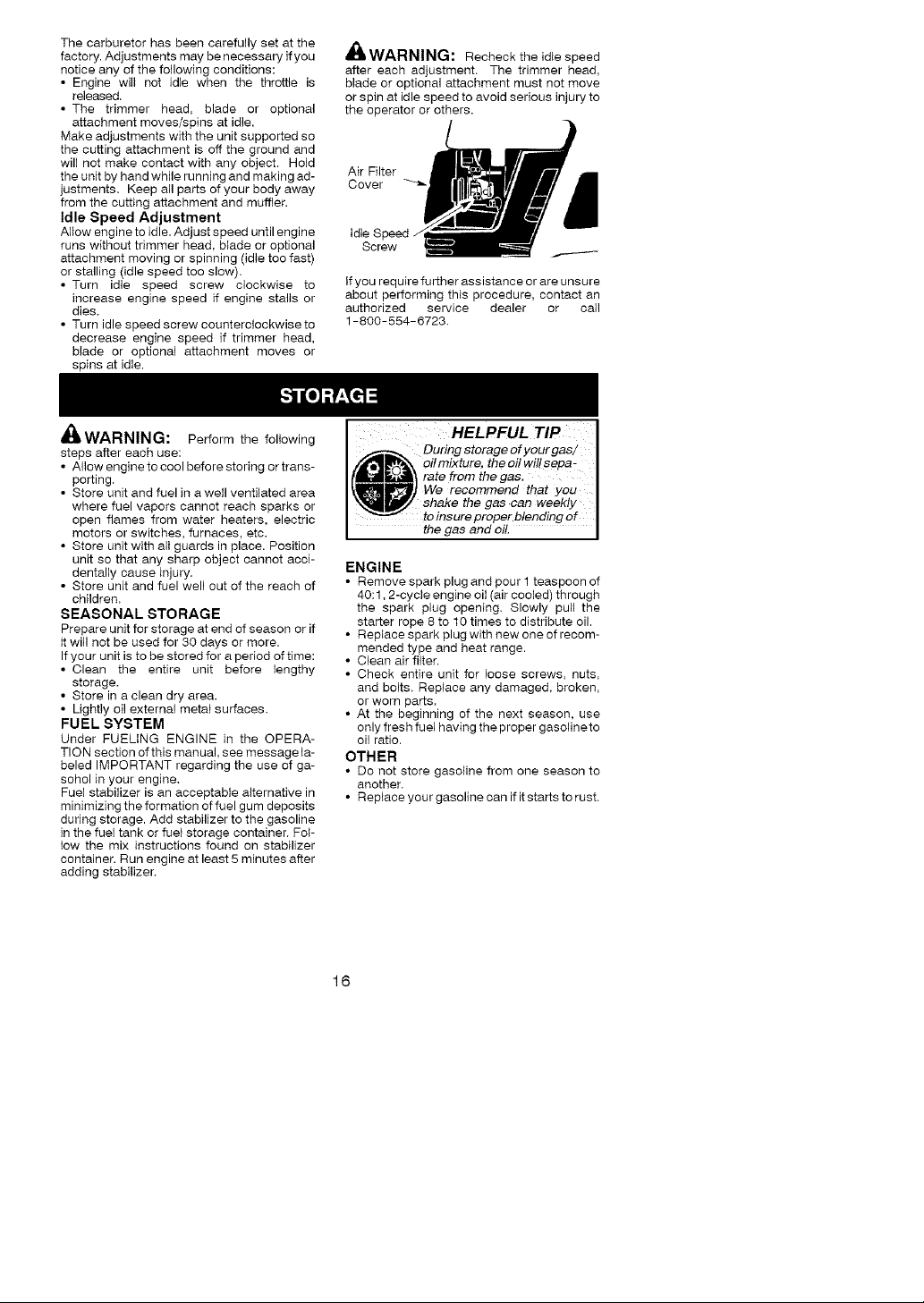
3. Insert one end of the line through the
positioning tunnel
4. Continue to feed line through tunnel until
line is centered (leaving equal amounts
on each side). See illustration below.
5. Insert ends of line one at a time through
the line exit tunnels.
6. Pull the line and make sure the line is ex-
tended fully through the tunnels.
Line exit Line exit
tunnel tunnel
7. Correctly installed line will be the same
length on both ends.
BLADE REPLACEMENT
Refer to the ASSEMBLY section for blade re-
placement instructions and illustrations.
CARBURETOR ADJUSTMENT
A_, WARNING: Keepothers away when
making idle speed adjustments. The trimmer
head, blade or any optional attachment will be
spinning during most of this procedure. Wear
your protective equipment and observe all safe-
ty precautions. After making adjustments, the
trimmer head, blade or any optional attachment
must not move/spin at idle speed.
15
The carburetor has been carefully set at the
factory. Adjustments may be necessary if you
notice any of the following conditions:
• Engine will not idle when the throttle is
released.
• The trimmer head, blade or optional
attachment moves/spins at idle.
Make adjustments with the unit supported so
the cutting attachment is off the ground and
will not make contact with any object. Hold
the unit by hand while running and making ad-
justments. Keep all parts of your body away
from the cutting attachment and muffler.
Idle Speed Adjustment
Allow engine to idle. Adjust speed until engine
runs without trimmer head, blade or optional
attachment moving or spinning (idle too fast)
or stalling (idle speed too slow).
• Turn idle speed screw clockwise to
increase engine speed if engine stalls or
dies.
• Turn idle speed screw counterclockwise to
decrease engine speed if trimmer head,
blade or optional attachment moves or
spins at idle.
A
_lJ WARNING: Recheck the idle speed
after each adjustment. The trimmer head,
blade or optional attachment must not move
or spin at idle speed to avoid serious injury to
the operator or others.
Cover
Air Filter _d
Idle Speed
Screw ...-------
if you require further assistance or are unsure
about performing this procedure, contact an
authorized service dealer or call
1-800-554-6723.
_WARNING: Perform the following
steps after each use:
• Allow engh_e to cool before storing or trans-
porting.
• Store unit and fuel h_aweII ventilated area
where fuel vapors cannot reach sparks or
open flames from water heaters, electric
motors or switches, furnaces, etc.
• Store unit with all guards in place. Position
unit so that any sharp object cannot acci-
dentally cause injury.
• Store unit and fuel well out of the reach of
children.
SEASONAL STORAGE
Prepare unit for storage at end of season or if
it will not be used for 30 days or more.
If your unit is to be stored for a period of time:
• Clean the entire unit before lengthy
storage.
• Store in a clean dry area.
• Lightly oil external metal surfaces.
FUEL SYSTEM
Under FUELING ENGINE in the OPERA-
TION section of this manual, see message la-
beled IMPORTANT regarding the use of ga-
sohol in your engine.
Fuel stabilizer is an acceptable alternative in
minimizing the formation of fuel gum deposits
during storage. Add stabilizer to the gasoline
in the fuel tank or fuel storage container. Fol-
low the mix instructions found on stabilizer
container. Run engine at least 5 minutes after
adding stabilizer.
HELPFUL TIP I
_j_'_ oilmixture, theoilwillsepa _
_[_,_l_ rate from the gae.
_) We recommend that you
_J shake the gas ear? weekly I
ENGINE
• Remove spark plug and pour 1 teaspoon of
40:1,2-cycle engine oil (air cooled) through
the spark plug opening. Slowly pull the
starter rope 8 to 10 times to distribute oil.
• Replace spark plug with new one of recom-
mended type and heat range.
• Clean air filter.
• Check entire unit for loose screws, nuts,
and bolts. Replace any damaged, broken,
or worn parts.
• At the beginning of the next season, use
only fresh fuel having the proper gasoline to
oil ratio.
OTHER
• Do not store gasoline from one season to
another.
• Replace your gasoline can if it starts to rust.
During storage of your gas/ I
to insure proper blending of I
the gas and oil. I
16

TROUBLESHOOTING TABLE
,_, WARN : Always stop unit anddisconnect spark plug before performing allofthe
ING
recommended remedies below except remedies that require operation of the unit.
TROUBLE
Engine will not
start.
Engine will 1. Carburetor requires
not idle adjustment.
properly. 2. Crankshaft seals worn.
Engine will not
accelerate,
lacks power.
or dies under
a load.
Engine
smokes
excessively.
Engine runs
hot.
CAUSE REMEDY
1.ON/OFF switch in
OFF position.
2. Engine flooded.
3. Fuel tank empty.
4. Spark plug not firing.
5. Fuel not reaching
carburetor.
6. Carburetor requires
adjustment.
3. Compression low.
1. Air filter dirty.
2. Spark plug fouled.
3. Carburetor requires
adjustment.
4. Carbon build-up on
muffler outlet screen.
5. Compression low.
1. Fuel mixture incorrect.
2. Air filter dirty.
3. Carburetor requires
adjustment.
1. Fuel mixture incorrect.
2. Spark plug incorrect.
3. Carburetor requires
adjustment.
4. Carbon build-up on
muffler outlet screen.
1. Move ON/OFF switch to the ON
position.
2. See "Starting a Flooded Engine" in
Operation Section.
3. Fill tank with correct fuel mixture.
4. Install new spark plug.
5. Check for dirty fuel filter; replace.
Check for kinked or split fuel line;
repair or replace.
6. Contact an authorized service dealer.
1. See "Carburetor Adjustment" in
Service and Adjustments Section.
2. Contact an authorized service dealer.
3. Contact an authorized service dealer.
1. Clean or replace air filter.
2. Clean or replace plug
and regap.
3. Contact an authorized service dealer.
4. Contact an authorized service dealer.
5. Contact an authorized service dealer.
1. Empty fuel tank and refill with
correct fuel mixture.
2. Clean or replace air filter.
3. Contact an authorized service dealer.
1.
See "Fueling Engine" in Operation
section.
2.
Replace with correct spark plug.
3.
Contact an authorized service dealer.
4.
Contact an authorized service dealer.
17

Poulan PRO warrants to the origh_al pur-
chaser that each new Poulan PRO brand
gasoih_e tool or attachment is free from de-
fects in material and workmanship and
agrees to repair or replace under this war-
ranty any defective gasoline product or at-
tachment as follows from the origh_al date of
purchase.
2 YEARS - Parts and Labor, when used for
household purposes.
90 DAYS - Parts and Labor, when used for
commercial, professional, or income produc-
ing purposes.
80 DAYS - Parts and Labor, if used for rental
purposes.
This warranty is not transferable and does not
cover damage or liability caused by improper
handling, improper maintenance, or the use
of accessories and/or attachments not spe-
cifically recommended by Poulan PRO for
this tool. Additionally, this warranty does not
cover tune-ups, spark pIugs, filters, cutting
lh_e, or rotating head parts that will wear and
require replacement with reasonable use dur-
ing the warranty period. This warranty does
not cover predelivery setup or normal adjust-
ments explained in the instruction manual.
THIS WARRANTY GIVES YOU SPECIFIC
LEGAL RIGHTS, AND YOU MAY HAVE
OTHER RIGHTS WHICH VARY FROM
STATE TO STATE.
NO CLAIMS FOR CONSEQUENTIAL OR
OTHER DAMAGES WILL BE ALLOWED,
AND THERE ARE NO OTHER EXPRESS
WARRANTIES EXCEPT THOSE EX-
PRESSLY STIPULATED HEREIN.
SOME STATES DO NOT ALLOW LIMITA-
TIONS ON HOW LONG AN IMPLIED WAR-
RANTY LASTS OR THE EXCLUSION OR
LIMITATIONS OF INCIDENTAL OR CON-
SEQUENTIAL DAMAGES, SO THE ABOVE
LIMITATIONS OR EXCLUSION MAY NOT
APPLY TO YOU.
The policy of Poulan PRO is to continuously
improve its products. Therefore, Poulan
PRO reserves the right to change, modify, or
discontinue models, designs, specifications,
and accessories of all products at any time
without notice or obligation to any purchaser.
YOUR WARRANTY RIGHTS AND OB-
LIGATIONS: The U.S. Environmental
Protection Agency/California Air Resources
Board, Environment Canada and Poulan
PRO are pleased to explain the emissions
control system warranty on your year 2007
and later small off-road engine. In California,
all small off-road engines must be designed,
built, and equipped to meet the State's strin-
gent anti-smog standards. Poulan PRO must
warrant the emission control system on your
small off-road engine for the periods of time
listed below provided there has been no
abuse, neglect, or improper maintenance of
your small off-road engine. Your emission
control system includes parts such as the
carburetor, the ignition system and the fuel
tank (California only). Where a warrantable
condition exists, Poulan PRO will repair your
small off-road engine at no cost to you. Ex-
penses covered under warranty include diag-
nosis, parts and labor. MANUFACTURER'S
WARRANTY COVERAGE: if any emissions
related part on your engine (as listed under
Emissions Control Warranty Parts List) is de-
fective or a defect in the materials or work-
manship of the engine causes the failure of
such an emission related part, the part will be
repaired or replaced by Poulan PRO. OWN-
ER'S WARRANTY RESPONSIBILITIES:
As the small off-road engine owner, you are
responsible for the performance of the re-
quired maintenance _isted in your instruction
manual. Poulan PRO recommends that you
retain all receipts covering maintenance on
your small off-road engine, but Poulan PRO
cannot deny warranty solely for the lack of re-
ceipts or for your failure to ensure the perfor-
mance of all scheduled maintenance. As the
small off-road engine owner, you should be
aware that Poulan PRO may deny you war-
ranty coverage if your small off-road engine
or a part of it has failed due to abuse, neglect,
improper maintenance, unapproved modifi-
cations, or the use of parts not made or ap-
proved by the original equipment manufactur-
er. You are responsible for presenting your
small off-road engine to a Poulan PRO autho-
rized repair center as soon as a problem ex-
ists. Warranty repairs should be completed in
a reasonable amount of time, not to exceed
30 days. If you have any questions regarding
your warranty rights and responsibilities, you
should contact your nearest authorized ser-
vice center or call Poulan PRO at
1-800-554-6723. WARRANTY COM-
MENCEMENT DATE: The warranty period
begins on the date the small off-road engine
is purchased. LENGTH OF COVERAGE:
This warranty shall be for a period of two
years from the initial date of purchase. WHAT
IS COVERED: REPAIR OR REPLACE-
MENT OF PARTS. Repair or replacement of
any warranted part wil_ be performed at no
charge to the owner at an approved Poulan
PRO servicing center. If you have any ques-
tions regarding your warranty rights and re-
sponsibilities, you should contact your near-
est authorized service center or call Poulan
PRO at 1-800-554-6723.
18
 Loading...