

Poulan Pro PP155A42 Important Manual
IMPORTANT MANUAL DO NOT THROW AWAY
REPAIR PARTS MANUAL
MODEL:
PP155A42
LAWN TRACTOR
ALWAYS WEAR EYE PROTECTION DURING OPERATION
Visit our website: www.poulanpro.com
589 88 63-01 Printed in the U.S.A.
WARNING:
Read this Man u al and follow all Warnings
and Safety Instructions. Fail ure to do so
can re sult in serious in ju ry.
10.31.16 BD

HOW TO USE THIS MANUAL
This manual is designed to provide the customer with a means to identify the parts on his/her tractor
when ordering repair parts. The illustrations may or may not represent the actual assemblies; therefore,
it is not recommended to use this manual as a guide to assemble or disassemble the tractor. Some
hardware and parts are drawn larger in order to more readily identify them.
Each tractor has its own model number.
The model number for your tractor can be found on the fender under the seat.
When ordering parts, always give the following information:
• Product - “TRACTOR”
• MODEL NUMBER - “PP155A42 (274430)”
• Part Number
• Part Description
TABLE OF CONTENTS
SCHEMATIC ................................................................................................................ 3
ELECTRICAL ............................................................................................................ 4-5
CHASSIS ..................................................................................................................6-7
DRIVE........................................................................................................................8-9
ENGINE ................................................................................................................. 10-11
STEERING ............................................................................................................12-13
MOWER DECK .....................................................................................................14-15
MOWER LIFT ............................................................................................................. 16
SEAT .......................................................................................................................... 17
DECALS .....................................................................................................................18
TRANSAXLE BREAKDOWN .................................................................................... 19
ENGINE BREAKDOWN ........................................................................................20-23
PARTS AND SERVICE .............................................................................................. 24
2
TRACTOR - MODEL NUMBER PP155A42 (274430), PRODUCT NO. 274430
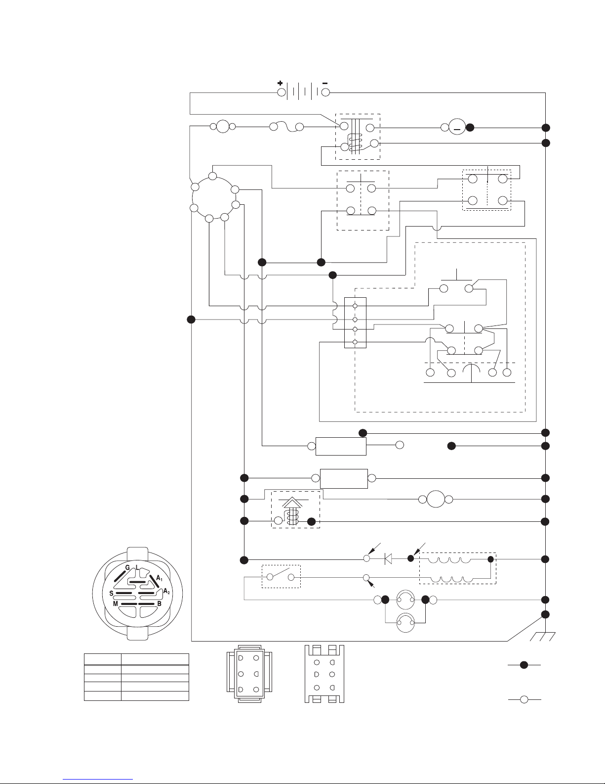
SCHEMATIC
SCH11
NOTE
YOUR TRACTOR IS
EQUIPPED WITH A SPECIAL
ALTERNATOR SYSTEM.
THE LIGHTS ARE NOT
CONNECTED TO THE
BATTERY, BUT HAVE THEIR
OWN ELECTRICAL SOURCE.
BECAUSE OF THIS, THE
BRIGHTNESS OF THE LIGHTS
WILL CHANGE WITH ENGINE
SPEED. AT IDLE THE LIGHTS
WILL DIM. AS THE ENGINE IS
SPEEDED UP, THE LIGHTS
WILL BECOME THEIR
BRIGHTEST.
RED
(OPTIONAL)
B
G
L
BLACK
A
AMMETER
S
M
A1
A2
WHITE
BATTERY
FUSE
BLACK
BLACK
BLACK /WHITE
BLUE
BLUE
FUEL SHUT-OFF
SOLENOID
(IF SO EQUIPPED)
RED
LIGHT SWITCH
DER
BLACK
IGNITION
(OPTIONAL)
FUEL
LINE
LIGHTING SYSTEM OUTPUT
5 AMP AC @ 3600 RPM
ORANGE
BROWN
SOLENOID
CLUTCH/BRAKE
(PEDAL UP)
2
3
1
6
JUNCTION
CONNECTOR
CHASSIS
HARNESS
UNIT
HOUR
METER
CHARGING SYSTEM OUTPUT
3AMPDC@3600RPM
DIODE
14 VOLTS AC MIN. @ 3600 RPM (LIGHTS OFF)
STARTER
BLACK
WHITE
REVERSE SWITCH
BLACK
BLACK
BLACK
BLACKBLACK
GRAY
PLUGS GAP
(2 PLUGS ON
TWIN CYL. ENGINES)
(NOT IN REVERSE)
SEAT SWITCH
(NOT OCCUPIED)
SPARK
BLACK
12V
POWER OUTLET
(OPTIONAL)
28 VOLTS AC MIN. @ 3600 RPM
(CHARGING SYSTEM DISCONNECTED)
ALTERNATOR
M
M
ATTACHMENT CLUTCH
(CLUTCH OFF)
BLACK
GRAY
SHORTING
CONNECTOR
BLACK
IGNITION SWITCH
POSITION
RUN/OVERRIDE
OFF
CIRCUIT
M+G+A1
B+A1
B+A1RUN
B+S+A1START
“MAKE”
L+A2
63
52
41
CHASSIS HARNESS
CONNECTOR
(MATING SIDE)
6
3
5
2
4
1
DASH HARNESS
CONNECTOR
(MATING SIDE)
3
HEADLIGHTS
WIRING INSULATED CLIPS
NOTE: IF WIRING INSULATED
CLIPS WERE REMOVED FOR
SERVICING OF UNIT, THEY
SHOULD BE RE-INSTALLED TO
PROPERLY SECURE YOUR
WIRING.
NON-REMOVABLE
CONNECTIONS
REMOVABLE
CONNECTIONS
REPAIR PARTS
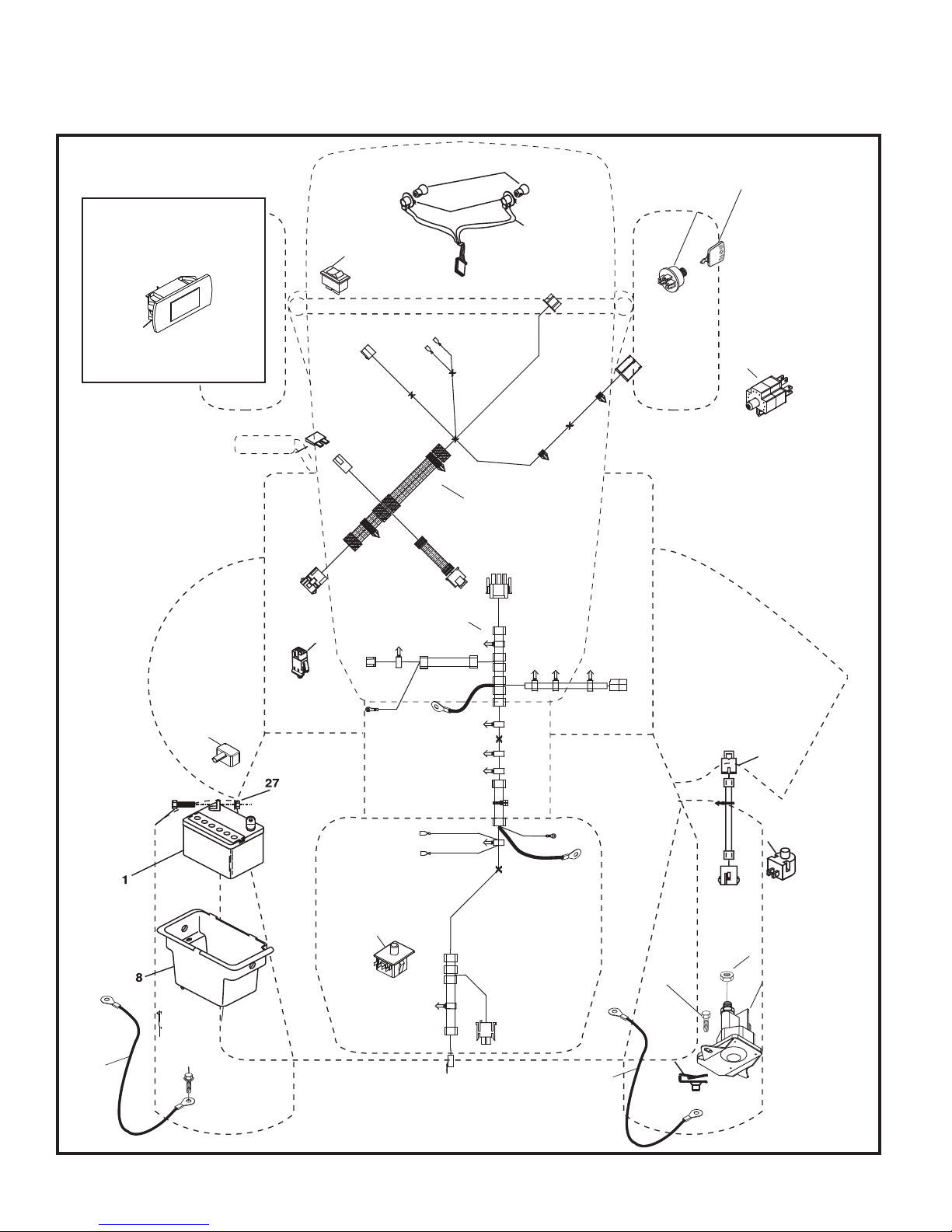
TRACTOR - MODEL NUMBER PP155A42 (274430), PRODUCT NO. 274430
ELECTRICAL
TR02K
Service Minder (If Equipped)
4646
26
34
79
22
21
40
33
30
87
28
16
90
2
29
71
102
105
27
43
55
99
106
25
4

REPAIR PARTS
TRACTOR - MODEL NUMBER PP155A42 (274430), PRODUCT NO. 274430
ELECTRICAL
KEY PART
NO. NO. DESCRIPTION
1 532 16 34-65 Battery
2 874 76 04-12 Bolt Hex Hd 1/4-20 unc x 3/4
8 532 19 32-28 Box Battery
16 532 17 61-38 Switch Interlock
21 532 00 41-52 Bulb Light
22 532 18 37-59 Harness Asm. Light
25 581 49 80-01 Cable Starter 8 Ga. 14" Red
26 532 17 51-58 Fuse 20 AMP
27 873 51 04-00 Nut Keps Hex 1/4-20 unc
28 532 42 16-86 Cable Ground 6 Ga. 12" Black
29 532 19 27-49 Switch Seat
30 532 19 33-50 Switch Ign
33 532 41 19-33 Key/Chain
34 532 11 07-12 Switch Light
40 581 02 31-01 Harness Ign Dash
43 582 04 28-01 Solenoid
55 817 06 05-12 Screw 5/16-18 x 3/4
71 501 13 37-01 Harness Chassis
79 532 17 52-42 Socket Asm. Bulb
87 532 19 78-02 Switch Interlock
90 532 43 53-95 Cover Terminal Battery
99 817 67 04-12 Screw Hexwsh Thdrol 1/4-20 x 3/4
102 581 02 34-01 Harness Pigtail
105 532 40 75-68 Switch Reverse
106 532 17 48-14 Palnut 1/4 Lugs
NOTE: All component dimensions given in U.S. inches
1 inch = 25.4 mm
5
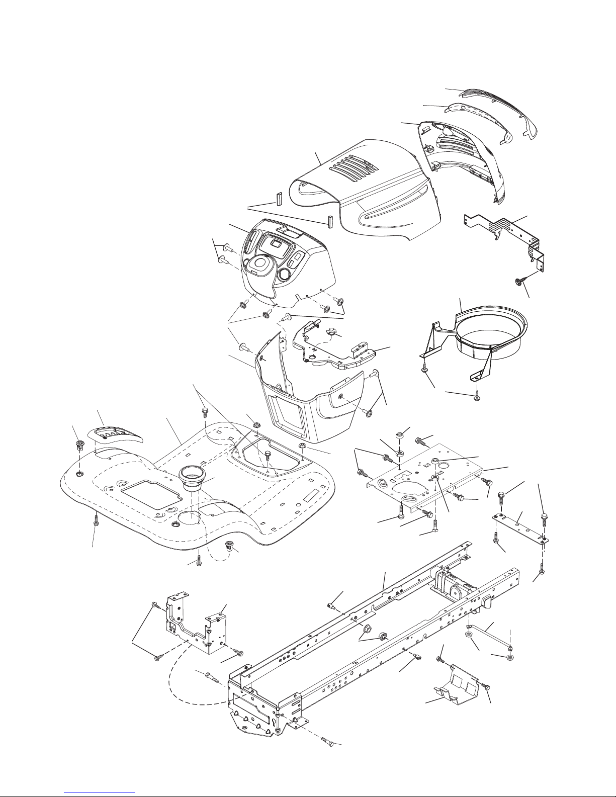
REPAIR PARTS
TRACTOR - MODEL NUMBER PP155A42 (274430), PRODUCT NO. 274430
CHASSIS
153
302
18
14
181
196
37
36
176
176
182
138
137
5
150
176
177
194
68
194
236
175
130
176
235
68
235
151
130
34
213
287
162
189
189
159
Chassis-tex_elite basic_5_r2
58
181
228
194
159
183
180
228
68
183
152
68
236
217
189
52
189
218
68
68
6

REPAIR PARTS
TRACTOR - MODEL NUMBER PP155A42 (274430), PRODUCT NO. 274430
CHASSIS
KEY PART
NO. NO. DESCRIPTION
5 532 41 17-64 Dash
14 532 18 65-80 Hood
18 532 42 67-92 Grille
34 580 91 08-01 Plate Engine
36 817 06 05-12 Screw 5/16-18 x 3/4
37 532 42 07-96 Fender
52 873 68 05-00 Nut Lock 5/16-18
58 532 41 22-80 Drawbar Upper 2 pc.
68 817 49 05-08 Screw Thdrol 5/16-18 x 1/2
130 532 41 63-58 Screw #10 x 0.750
137 532 18 49-21 Bumper Hood
138 532 40 97-30 Cupholder
150 532 18 44-61 Duct Heat Hood
151 532 40 78-07 Bracket Pivot
152 532 19 95-35 Shield Browning
153 532 18 98-37 Lens Grille
159 817 00 06-12 Screw Hexwsh Thdrol 3/8-16 x 3/4
162 532 14 24-32 Screw Hex Wsh Hi-Lo 1/4 x 1/2
175 532 19 32-43 Crossmember
176 532 40 07-76 Screw 10-24 x 5/8 Wshd Qdrx
177 532 19 52-28 Bushing Steering
180 532 41 50-63 Chassis
181 532 40 47-96 Bushing Mtg. Fender Crgo.
182 532 19 30-57 Dash Lower
183 874 52 05-20 Bolt 5/16-18 x 1-1/4
189 817 00 05-12 Screw 5/16-18 x 3/4
194 873 90 05-00 Nut Lock Hex Flange 5/16-18
196 532 41 45-81 Console Asm. Deck Lift
213 874 76 05-12 Bolt 5/16-18 x 3/4
217 532 40 91-67 Rod Pivot Hood
218 532 19 63-95 X-Piece Hood Step
228 532 19 51-61 Stud Fastener
235 532 40 61-29 Spacer Fender
236 873 93 05-00 Nut Center Lock 5/16-18
287 817 60 04-06 Screw 1/4-20 x 3/8
302 532 18 38-23 Insert Lens Reflective
NOTE: All component dimensions given in U.S. inches
1 inch = 25.4 mm
7
REPAIR PARTS
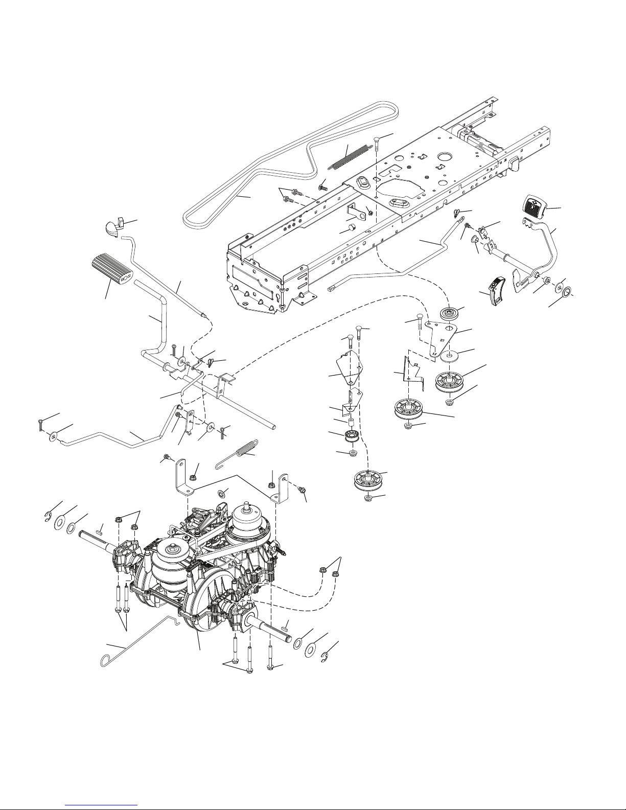
TRACTOR - MODEL NUMBER PP155A42 (274430), PRODUCT NO. 274430
DRIVE
306
33
15
37
205
42
303
190
301
51
185
49
163
51
125
52
215
186
160
211
189
187
51
50
277
214
210
222
211
166
161
345
143
56
184
35
64
203
159
188
29
2
125
374
125
116
67
116
167
160
159
172
378
17
299
300
373
302
375
116
125
51
195
6
5
73
99
1
73
2
282
116
205
37
33
drive-tex_VATR_PEDAL_43
8

REPAIR PARTS
TRACTOR - MODEL NUMBER PP155A42 (274430), PRODUCT NO. 274430
DRIVE
KEY PART
NO. NO. DESCRIPTION
1 – – – – – – Transaxle, Variator SD Pedal
(587884401) (Order parts from
transaxle manufacturer.)
2 532 12 35-83 Key Square
5 874 76 06-36 Bolt Hex HS 3/8-16 unc x 2-1/4
6 532 12 40-28 Bushing Snap
15 819 13 13-16 Washer 13/32 x 13/16 x 16 Ga.
17 501 48 71-01 Spring, Brake
29 584 82 31-01 Rod, Brake
33 812 00 00-01 Ring E
35 532 19 77-22 Rod, Brake, Park
37 532 18 89-67 Washer .793 x 1.637 x 060
42 532 12 48-72 Cover, Foot Pedal
49 872 11 06-14 Bolt 3/8-16 unc
50 532 19 43-27 Idler Flat
51 873 90 06-00 Nut Lock
52 532 19 43-26 Idler V-Groove
56 532 19 72-53 V-Belt, Drive
64 532 44 83-53 Subasm. Shaft Pedal Brake
67 582 58 01-01 Washer Nylon 13/32 x 13/16 x .109
73 874 49 05-44 Bolt Hex 5/16-18 x 3.75
99 532 43 59-35 Rod Bypass
116 873 90 05-00 Nut Lock Hex Flange 5/16-18
125 817 00 05-12 Screw 5/16-18 x 3/4
143 817 49 05-08 Screw Thdrol 5/16-18 x 1/2 TYTT
159 876 02 04-12 Pin Cotter 1/8 x 3/4
160 532 16 94-84 Retainer Clip
161 532 10 57-09 Spring, Return, Clutch
163 587 84 79-02 Rod Control
166 532 42 91-64 Nut Push .625
167 532 40 52-57 Latch Brake Parking
172 583 97 42-01 Strap Torque Variator
184 532 40 96-30 Handle Park Brk.
185 872 11 06-22 Bolt 3/8-16 unc x 2-3/4
KEY PART
NO. NO. DESCRIPTION
186 532 19 43-21 Spacer Retainer
187 819 13 32-10 Washer 13/32 x 2 x 10 ga
188 582 21 70-01 Link Clutch Ground Drive Long
189 532 19 43-17 Bellcrank Ground Drive
190 532 19 43-18 Keeper. Bellcrank
195 581 50 46-01 Bracket Brake
203 819 11 11-16 Washer 11/32 x 11/16 x 16
205 532 12 17-48 Washer 25/32 x 1-5/8 16 Ga.
210 588 92 10-01 Rocker Asm. Pedal
214 532 42 12-63 Pedal Forward
215 532 44 82-54 Pad Pedal Reverse
211 532 12 01-83 Bearing Nylon
222 879 21 20-10 Washer Flat
277 532 44 85-00 Subasm. Link Rocker Pedal
282 874 49 05-48 Bolt Hex 5/16-18
299 532 41 56-83 Bracket Mount
300 532 41 56-81 Keeper Idler
301 532 41 56-80 Pulley Idler Groove
302 581 42 05-01 Puller Idler Flat
303 872 11 06-18 Bolt
306 876 02 04-16 Pin Cotter
345 872 11 06-06 Bolt RDHD
373 581 46 18-01 Spacer Idler
374 581 47 52-01 Arm Control Brake
375 873 68 06-00 Nut Crownlock 3/8-16 unc
378 584 28 77-01 Nut Push 8 mm
NOTE: All component dimensions given in U.S. inches
1 inch = 25.4 mm
9
REPAIR PARTS
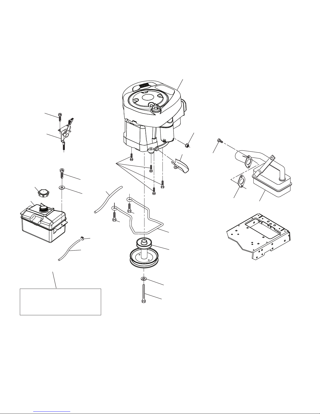
TRACTOR - MODEL NUMBER PP155A42 (274430), PRODUCT NO. 274430
ENGINE
1
21
15
18
20
29
97
28
96
37
138
84
90
90
9
12
122
45
79
69
2
OPTIONAL EQUIPMENT
Spark Arrester
42
85
engine-tex_BS_128
10

REPAIR PARTS
TRACTOR - MODEL NUMBER PP155A42 (274430), PRODUCT NO. 274430
ENGINE
KEY PART
NO. NO. DESCRIPTION
1 – – – – – – Engine, B&S 31R707-0001-G1 (585926001)
(Order parts from engine manufacturer.)
2 532 13 73-52 Muffler Exhaust B&S
9 582 54 03-02 Keeper Belt Engine
12 586 72 90-01 Pulley Engine
15 532 43 30-03 Tank Fuel Front
18 581 17 61-01 Cap Asm Fuel
20 532 17 05-45 Control Th/ch Flag
21 532 41 63-58 Screw #10 x 0.750
28 532 40 11-37 Line Fuel
29 532 13 71-80 Kit Spark Arrestor (Flat Scrn)
37 532 12 34-87 Clamp Hose
42 539 99 02-47 Washer Lock 7/16
45 873 51 04-00 Nut Keps Hex 1/4-20 unc
69 532 16 52-91 Gasket Eng 1 313 Id Tin Plated
79 532 19 23-34 Screw Socket Head 5/16-18 x 3/4
84 817 06 06-20 Screw 3/8-16 x 1-1/4
85 501 60 65-01 Bolt Hex 7/16-20 x 4 x Gr 5
90 817 00 06-16 Screw 3/8-16 x 1
96 819 09 14-16 Washer 9/32 x 7/8 x 16 Ga.
97 817 67 04-12 Screw Thdrol 1/4-20 x 3/4
122 532 42 19-22 Extension Drain Oil
138 532 41 41-19 Purge Line
NOTE: All component dimensions given in U.S. inches
1 inch = 25.4 mm
For engine service and replacement parts, call the toll free
number for your engine manufacturer listed below:
Briggs & Stratton 1-800-233-3723
Engine Power Rating Information
The gross power rating for individual gas engine models is labeled in accordance with SAE (Society of Automotive
Engineers) code J1940 (Small Engine Power & Torque Rating Procedure), and rating performance has been obtained
and corrected in accordance with SAE J1995 (Revision 2002-05). Torque values are derived at 3060 RPM; horsepower
values are derived at 3600 RPM. Actual gross engine power will be lower and is affected by, among other things, ambient operating conditions and engine-to-engine variability. Given both the wide array of products on which engines are
placed and the variety of environmental issues applicable to operating the equipment, the gas engine will not develop
the rated gross power when used in a given piece of power equipment (actual “on-site” or net power). This difference is
due to a variety of factors including, but not limited to, accessories (air cleaner, exhaust, charging, cooling, carburetor,
fuel pump, etc.), application limitations, ambient operating conditions (temperature, humidity, altitude), and engine-toengine variability. Due to manufacturing and capacity limitations, Briggs & Stratton may substitute an engine of higher
rated power for this Series engine.
11

REPAIR PARTS
TRACTOR - MODEL NUMBER PP155A42 (274430), PRODUCT NO. 274430
STEERING
26
72
33
45
1
20
19
63
57
64
16
122
35
28
21
75
76
27
59
28
71
22
60
57
122
63
9
8
7
74
6
74
2
67
66
9
7
8
74
58
4
61
69
68
steering-tex_STDHRS_21
14
15
70
12
67
62
14
15
74
6
5
13
8
13
53

REPAIR PARTS
TRACTOR - MODEL NUMBER PP155A42 (274430), PRODUCT NO. 274430
STEERING
KEY PART
NO. NO. DESCRIPTION
1 532 42 45-43 Wheel, Steering
2 532 41 81-68 Axle Asm., Front
4 532 40 30-87 Spindle Asm., LH
5 532 40 30-88 Spindle Asm., RH
6 532 12 49-31 Washer Thrust 0.75 x 1.23
7 532 12 17-48 Washer 25/32 x 1-5/8 x 16 Ga.
8 812 00 00-29 Ring, Clip #T5304-75
9 532 12 12-32 Cap, Spindle
13 532 12 17-49 Washer 25/32 x 1-1/4 x 16 Ga.
14 810 04 06-00 Washer Lock 3/8
15 873 54 06-00 Nut, Crown Lock 3/8-24 unf
16 585 86 92-02 Shaft Steering
19 532 19 47-29 Plate Steering
20 532 41 12-91 Boot, Steering
21 532 18 67-37 Adapter, Wheel Steering
22 585 02 98-02 Bearing Subasm Shaft Steer Low
26 532 42 46-91 Insert, Wheel Steering
27 819 21 16-16 Washer 21/32 x 1 x 16 Ga.
28 817 00 06-12 Screw 3/8-16 x 3/4
33 810 04 05-00 Washer Lock 5/16
35 532 19 47-32 Gear, Sector Plate
45 819 11 38-12 Washer 11/32 x 2-3/8 x 12 Ga.
53 532 18 89-67 Washer Hardened .793 x 1.637 x .060
57 532 40 74-65 Bracket Upstop
58 532 19 47-47 Bolt Shoulder Sector Pivot CFM
59 532 19 47-48 Washer Thrust Sector Steering
60 873 97 10-00 Nut Flange Lock 5/8-11
61 532 19 47-40 Draglink, LH
62 532 19 47-41 Draglink, RH
63 817 00 05-12 Screw 5/16-18 x 3/4
64 532 19 98-49 Retainer Clip Spring Steering
66 871 02 07-48 Bolt Hex Fghd 7/16-14 x 3 Serr
67 532 19 47-37 Bushing PM Front Axle
68 873 90 07-00 Nut Lock Flange 7/16-14 Gr. 5
69 532 19 91-62 Washer 1.5 x .505 x .118
70 585 33 88-01 Bracket Deck Susp. Front
71 532 19 07-52 Shaft Ext. Steering
72 532 42 89-82 Bolt 5/16-18 x 4 W/Patch
74 532 12 49-37 Bearing
75 580 68 37-01 Pinion
76 580 68 36-01 Screw Head Sock
122 532 44 49-62 Cap Gear
NOTE: All component dimensions given in U.S. inches
1 inch = 25.4 mm
13

REPAIR PARTS
41
41
43
42
60
38
63
46
147
55
64
47
192
56
56
57
62
188
189
1
69
21
21
69
69
20
40
145
21
24
25
26
27
29
23
189
188
144
36
113
113
40
57
19
19
6
6
68
41
41
32
38
195
122
123
195
33
34
59
14
13
11
12
208
42_D_man-tex_LT_55_r4
15
TRACTOR - MODEL NUMBER PP155A42 (274430), PRODUCT NO. 274430
MOWER DECK
152
70
37
67
7
7
14

REPAIR PARTS
TRACTOR - MODEL NUMBER PP155A42 (274430), PRODUCT NO. 274430
MOWER DECK
KEY PART
NO. NO. DESCRIPTION
1 532 19 99-11 Mower Housing
6 532 19 51-86 Arm Suspension
7 532 41 63-58 Screw #10 x 0.750 BOS Thread
11 532 13 89-71 Blade, 42" Hi-Lift
(For bagging or discharge)
- - 532 13 97-75 Blade, 42" Mulching Premium
(For better wear when mulching)
- - 532 13 41-49 Blade, 42" Mulching Std
(For mulching mowers only)
- - 532 42 47-52 Blade 42SP" 3N1
- - 532 42 27-19 Blade 42SP" Premium
12 584 30 93-01 Screw Sems 7/16-20 x 1 Hx Hd
13 587 25 65-01 Shaft Assembly, Mandrel
14 532 18 72-81 Housing, Mandrel
15 585 32 39-01 Bearing, Mandrel
19 532 19 65-39 Bolt, Shoulder
20 532 15 97-70 Baffle, Vortex
21 873 68 05-00 Nut, Crownlock 5/16-18 unc
23 532 19 25-57 Bracket, Deflector
24 532 10 53-04 Cap, Sleeve
25 532 19 70-26 Spring, Torsion, Deflector
26 532 11 04-52 Nut, Push
27 532 40 30-04 Shield, Deflector
29 532 13 14-91 Rod, Hinge
32 532 19 74-73 Pulley, Mandrel
33 532 40 02-34 Nut, Toplock, Flanged
34 872 11 06-12 Bolt Carr Sh. 3/8-16 x 1-1/2 Gr. 5
36 532 19 73-79 Pulley, Idler 4.50 RAW
37 819 13 13-16 Washer 13/32 x 13/16 x 16 Ga.
38 532 43 25-20 Keeper Belt Mandrel
40 873 90 06-00 Nut, Lock Flg. 3/8-16 unc
41 584 95 39-01 Bolt Hex Wsh Hd 313-18 x 1.19
42 532 19 84-10 Spring Torsion Brake
43 532 19 72-56 Spring Torsion Retainer
46 532 13 77-29 Screw Thd Roll 1/4-20 x 5/8
47 532 19 72-50 Bracket Clutch Cable
KEY PART
NO. NO. DESCRIPTION
55 532 43 71-10 Arm, Idler
56 532 19 90-92 Spacer, Retainer
57 817 00 06-16 Screw Hexwsh Thd 3/8-16 x 1
59 532 14 10-43 Guard, Tuv Idler (94)
60 532 19 72-61 Arm Brake Mower
62 872 11 06-16 Bolt Rdhd Sqnk 3/8-16 unc x 2
63 532 19 94-77 Arm Brake Mower
64 532 19 97-90 Linkage Brake
67 532 40 30-12 Handle, Clutch Cable
68 532 42 96-36 V-Belt
69 872 14 05-05 Bolt Rdhd Sqnk 5/16-18 x 5/8
70 532 19 83-32 Clutch Asm. Manual
113 817 00 05-10 Screw 5/16-18
122 532 19 72-58 Keeper Belt Eng. LH
123 532 19 72-59 Keeper Belt Eng. RH
144 532 19 92-04 Keeper Belt
145 532 19 31-97 Pulley Idler Primary
147 532 40 19-71 Spring Return
152 584 24 35-01 Cable Clutch Manual
188 532 19 51-61 Stud Fastener
189 873 90 05-00 Nut Lock Hex Flange
192 532 19 72-60 Bracket Brake Stand LH
195 817 00 06-12 Screw Hexwsh Thdr 3/8-16 x 3/4
208 817 67 06-08 Screw THDROL 3/8-16 x 1/2
- - 587 25 33-01 Mandrel Assembly (Includes
housing (key#14), shaft assembly (key#13), and bearing only
(key#15) - pulley/nut/washer and
blade bolt/washers not included)
- - 532 41 52-41 Replacement Mower, Complete
NOTE: All component dimensions given in U.S. inches
1 inch = 25.4 mm
15
 Loading...