

Page 1
OWNER'S MANUAL
MODEL NO. CHDF550D
5 HP 26 Inch
T)0
Tiller
Assembly
• Operation
• Customer Responsibilities
• Service and Adjustments
• Storage
• Troubleshooting
• Repair Parts
Pouian
This product has a low emission engine which operates differently ^
from pre¥looaly built engines. Before you start the engine, read:;
and understand.Ais; Owiwi«; .Manual.
164784 2.5,98 TR
PRINTED IN U.S.A.
Page 2

SAFETY RULES
A
Safe Operation Practices for Waik-Behind Powered Rotary Tillers Л
TRAINING
• Read the Owner’s Manual carefully. Be thoroughly
familiar with the controls and the proper use of the
equipment. Know how to stop the unit and disengage
the controls quickly.
• Never allow children to operate the equipment. Never
allow adults to operate the equipment without proper
instruction.
• Keep the area of operation clear of ail persons, particu
larly small children, and pets.
PREPARATION
• Thoroughly inspect the area where the equipment is to
be used and remove all foreign objects.
• Disengage all clutches and shift into neutral before
starting the engine (motor).
• Do not operate the equipment without wearing ad
equate outer garments. Wear footwear that will im
prove footing on slippery surfaces.
• Handle fuel with care; it is highly flammable.
• Use an approved fuel container.
• Never add fuel to a running engine or hot engine.
• Fill fuel tank outdoors with extreme care. Never fill fuel
tank indoors.
• Replace gasoline cap securely and clean up spilled
fuel before restarting.
• Use extension cords and receptacles as specified by
the manufacturer for all units with electric drive motors
or electric starting motors.
• Never attempt to make any adjustments while the
engine (motor) is running (except where specifically
recommended by manufacturer).
OPERATION
Do not put hands or feet near or under rotating parts.
Exercise extreme caution when operating on or cross
ing gravel drives, walks, or roads. Stay alert for hidden
hazards or traffic. Do not carry passengers.
After striking a foreign object, stop the engine (motor),
remove the wire from the spark plug, thoroughly in
spect the tiller for any damage, and repair the damage
before restarting and operating the tiller.
Exercise caution to avoid slipping or falling.
If the unit should start to vibrate abnormally, stop the
engine (motor) and check immediately for the cause.
Vibration is generally a warning of trouble.
Stop the engine (motor) when leaving the operating
position.
Take all possible precautions when leaving the ma
chine unattended. Disengage the tines, shift into
neutral, and stop the engine.
Before cleaning, repairing, or inspecting, shut off the
engine and make certain all moving parts have stopped.
Disconnect the spark plug wire, and keep the wire
away from the plug to prevent accidental starting.
Disconnect the cord on electric motors.
Do riot run the engine indoors; exhaust fumes are
dangerous.
Never operate the tiller without proper guards, plates,
or other safety protective devices in place.
Kepp ■•hildre'"i and pet-. jWcj
Do n<4 overln )6 ;r-'. rr-a,hiofc r ipacity by attempting to
till *bo deep j* tov, fast a rate
Never upetate ttrr- rnacl'iine at fityh speeds on slippery
surfaces. Look oenind and u=e care when backing.
Nevei allow Ьуыапоегь riear the unit.
Use only attachments and accessories approved by
the manufacturer of the tiller.
Never operate the tiller without good visibility or light.
Be careful when tilling in hard ground. The tines may
catch in the ground and propel the tiller forward. If this
occurs, let go of the handlebars and do not restrain the
machine.
MAINTENANCE AND STORAGE
• Keep machine, attachments, and accessories in safe
working condition.
• Check shear pins, engine mounting bolts, and other
bolts at frequent intervals for proper tightness to be
sure the equipment is in safe working condition.
• Never store the machine with fuel in the fuel tank inside
a building where ignition sources are present, such as
hot water and space heaters, clothes dryers, and the
like. Allow the engine to cool before storing in any
enclosure.
• Always refer to the operator’s guide instructions for
important details If the tiller is to be stored for an
extended period.
- IMPORTANT -
CAUTIONS, IMPORTANTS, AND NOTES ARE A MEANS
OF ATTRACTING ATTENTION TO IMPORTANT OR
CRITICAL INFORMATION IN THIS MANUAL.
IMPORTANT: USED TO ALERT YOU THAT THERE IS A
POSSIBILITY OF DAMAGING THIS EQUIPMENT.
NOTE: Gives essential information that will aid you to
better understand, incorporate, or execute a particular set
of instructions.
Look for this symbol to point out im
portant safety precautions. It means
A
A
CAUTION!!! BECOME ALERT!!! YOUR
SAFETY IS INVOLVED.
CAUTION: Always disconnect spark
plug wire and place wire where it can
not contact spark plug in order to pre
vent accidental starting when setting
up, transporting, adjusting or making
repairs.
A WARNING A
The engine exhaust from this product con
tains chemicals known to the State of Califor
nia to cause cancer, birth defects, or other
reproductive harm.
Page 3

CONGRATULATIONS on your purchase of a new tiller. It
las been designed, engineered and manufactured to give
PRODUCT SPECIHCATIONS
/ou the best possible dependability and performance.
Should you experience any problems you cannot easily
ernedy, please contact your nearest authorized service
enier We have f;onipetent, well-trained technicians and
HORSEPOWER:
DISPLACEMENT:
5.0 HP
12.57 cu. in. (206cc)
life Dropet loois 10 serv'c.e or repair this unit.
dease '•ead and retain this manual. The instructions will
¡nablfe you to asserribie and maintain your tiller properly.
GASOLINE CAPACITY:
3 Quarts (2.8L)
Unleaded Regular
\l»ays observe the “SAFE-TY RULES”.
MODEL
OIL (AFi-3F/SG/3H):
(CAPACITY: 20 OZ./0.6L)
SAE 30 (Above 32“F/0=C)
SAE 5W-30 (Below 32'^F/0“C)
NUMBER CHDF550D
SERIAL
NUMBER
___________
SPARK PLUG:
(GAP: .03070.76mm) RJ19LM
Champion
DATE OF PURCHASE
THE MODEL AND SERIAL NUMBERS WILL BE
FOUND ON THE MODEL PLATE ATTACHED TO
THE RIGHT HAND ENGINE BRACKET.
YOU SHOULD RECORD BOTH SERIAL NUMBER
AND DATE OF PURCHASE AND KEEP IN A SAFE
PLACE FOR FUTURE REFERENCE.
MPORTANT: THIS UNIT IS EQUIPPED WITH AN INTERNAL COMBUSTION ENGINE AND SHOULD NOT BE USED ON OR
lEAR ANY UNIMPROVED FOREST-COVERED, BRUSH-COVERED OR GRASS COVERED LAND UNLESS THE ENGINE'S
iXHAUST SYSTEM IS EQUIPPED WITH A SPARK ARRESTER MEETING APPLICABLE LOCAL LAWS (IF ANY). IF A
iPARK ARRESTER IS USED, IT SHOULD BE MAINTAINED IN EFFECTIVE WORKING ORDER BY THE OPERATOR.
N THE STATE OF CALIFORNIA, A SPARK ARRESTER IS REQUIRED BY LAW (SECTION 4442 OF THE CALIFORNIA
»UBLIC RESOURCES CODE). OTHER STATES MAY HAVE SIMILAR LAWS. FEDERAL LAWS APPLY ON FEDERAL
,ANDS. SEE YOUR AUTHORIZED SERVICE CENTER/DEPARTMENT FOR SPARK ARRESTER.
CUSTOMER RESPONSIBILITIES
• Read and observe the safety rules.
• Followaregularschedule in maintaining, caring forand
using your tiller.
• Follow instructions under “Customer Responsibilities”
and “Storage” sections of this Owner’s Manual.
Page 4

TABLE OF CONTENTS
SAFETY RULES ........................................... 2
PRODUCT SPECIFICATIONS ......................................3
CUSTOMER RESPONSIBILITIES .....................3, 11-13
WARRANTY .............................................................. 4
assembly .............................................................5-6
MAINTENANCE SCHEDULE.............................................
SERYiCE & ADJUSTMENTS................................. 13-15
STORAGE, . . .............................................16
TROUBLESHOOTING ............................................. 17
REPAIR PARTS-TILLER........................................ 13-23
OPERATION.............................................................7-10
LIMITED WARRANTY
The Manufacturer warrants to the original consumer purchaser that this product as manufactured is free from defects in
materials and workmanship. For a period of two (2) years from date of purchase by the original consumer purchaser, we will
repair or replace, at our option, without charge for parts or labor incurred in replacing parts, any part which we find to be
defective due to materials or workmanship. This Warranty is subject to the following limitations and exclusions.
1. This warranty does not apply to the engine or components parts thereof. Please refer to the applicable manufacturer's
warranty on these items.
2. Transportation charges for the movement of any power equipment unit or attachment are the responsibility of the
purchaser. Transportation charges for any parts submitted for replacement under this warranty must be paid by the
purchaser unless such return is requested by American Yard Products.
3. The Warranty period for any products used for rental or commercial purposes is limited to 90 days from the date of
original purchase.
4. This Warranty applies only to products which have been properly assembled, adjusted, operated, and maintained in
accordance with the instructions furnished. This Warranty does not apply to any product which has been subjected to
alteration, misuse, abuse, improper assembly or installation, delivery damage, or to normal wear of the product.
5. Exclusions: Excluded from this Warranty are belts, tines, tine adapters, normal wear, normal adjustments, standard
hardware and normal maintenance.
6. In the event you have a claim under this Warranty, you must return the product to an authorized service dealer.
Should you have any unanswered questions concerning this Warranty, please contact:
American Yard Products Canada contact:
Service Department American rard rrouucts
p Q 1037 1580 Trinity Drive, Units 5-8
Oranqeburq.se 29116 USA Mississauga, Ontario
L5T 1L6
.11
giving the model number, serial number and date of purchase of your product and the name and address of the authorized
dealer from whom it was purchased.
THIS WARRANTY DOES NOT APPLY TO INCIDENTAL OR CONSEQUENTIAL DAMAGES AND ANY IMPLIED WARRAN
TIES ARE LIMITED TO THE SAME TIME PERIODS STATED HEREIN FOR OUR EXPRESSED WARRANTIES. Some areas
do not allow the limitation of consequential damages or limitations of how long an implied Warranty may last, so the above
limitations or exclusions may not apply to you. This Warranty gives you specific legal rights, and you may have other rights
which vary from locale to locale.
This is a limited Warranty within the meaning of that term as defined in the Magnuson-Moss Act of 1975.
Page 5
ASSEMBLY
iour new tiller has been assembled at the factory with exception of those parts left unassembled for shipping purposes. To
insure safe and proper operation of your tiller all parts and hardware you assemble must be tightened securely. Use the
;orrect tools as necessary to insure proper tightness.
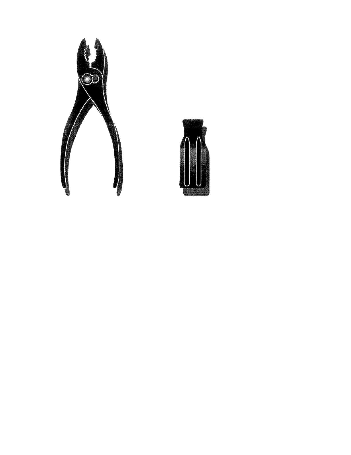
TOOLS REQUIRED FOR ASSEMBLY
t socket wrench set will make assembly easier. Standard
trench sizes are listed.
1) Utility knife
1) Pair of pliers
1) Screwdriver
2) 1/2“ wrenches
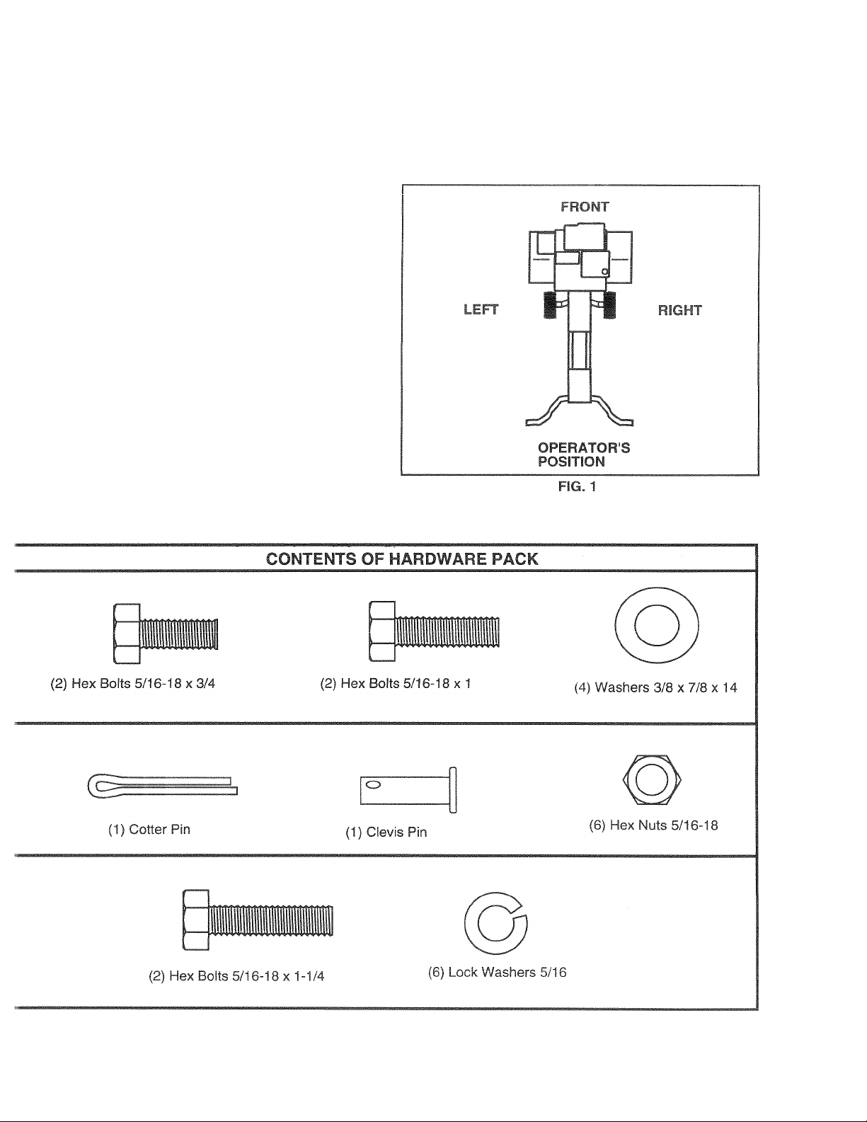
JPERATOR’S POSITION (See Fig. 1)
Vhen right or left hand is mentioned in this manual, it
leans when you are in the operating position (standing
¡ehind tiller handles).
Page 6
ASSEMBLY
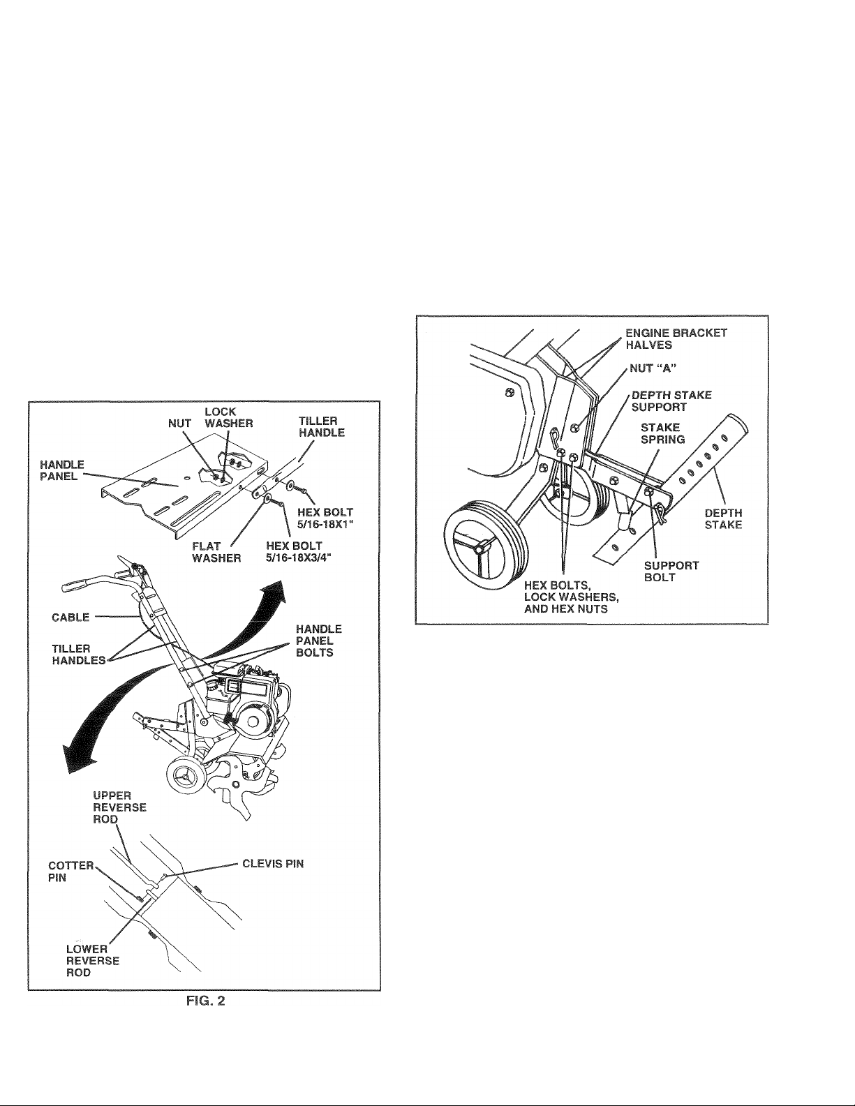
UNPACK CARTON & INSTALL HANDLE (See Fig. 2|
C ^UTiON Be careful of exposed
staples wt-.en handling or disposing of
A
IMPORTANT: WHEN UNPACKING AND ASSEMBLING
TILLER, BE CAREFUL NOT TO STRETCH OR KINK
CABLE(S).
* Cut cable ties securing handles.
« Slowly lift handle assembly up and align handle holes
with handle panel hole and slot.
e Loosely assemble hardware as shown. Bs sure the
shorter (3/4“ long) hex bolt is assembled in lower hole
of handle. Repeat for opposite side. Tighten all
hardware securely.
• Cut cable ties securing tiller to skid and remove tiller
from skid.
cartonlfig materia!.
INSTALL DEPTH STAKE ASSEMBLY
(See Fig. 3)
• Loosen nut “A” .
® inaerl staKe support between engine bracket halves
with stake spring down.
s Bolt stake support to engine brackets with bolts, lock
washers and nut.s. Tighten securely. Tighten nut “A”.
• Depth stake must move freely. If it does not, loosen
support bolt.
INSTALL REVERSE ROD (See Fig. 2)
• Secure upper reverse rod to lower reverse rod using
clevis pin. Secure with cotter pin.
FIG. 3
HANDLE HEIGHT
® Handle height may be adjusted to better suit operator.
(See “HANDLE HEIGHT” in the Service and Adjust
ments section of this manual).
TILLING WIDTH
• Tilling width may be adjusted to better handle your
tilling conditions (See “TINE .ARRANGEMENT” in the
Service and .Adjustments section of this manual).
TINE OPERATION
• Check tine operation before first use. (See “TINE
OPERATION CHECK” in the Service and Adjustments
section of this manual).
Page 7
opmmtfm
I ti.v# ^ H-t
READ THIS OWNER'S MANUAL ÄND SAFETY RULES BEFORE OPERATING YOUR TILLER.
I ■( p^.< il iify fi iii<
II I I nil I lOt u.'l It i-t^i II t.
It
«Iti V»Ui nil'*!
II)
^ il.iillt.'L S V‘ yt . ir//lif li f I X Ji u,1 I ■ i. >|i . I Olilyil (lU iij.itlr’iciit:- W.vf
ye, ri S(<j
4-I* h 5 f ^ on your Tiller or in iiieraiure sypp'ied with the LtMirs.-r.u »nWi Sino •tiC r
I N R A (S H ^ k i\i Q "fir
1LUNG FORWARD NEUTRAL REVERSE CAUTION ENGINE ENGINE
OR WARNING ON OFF
FAS T
SLOW CHOKE FUEL OIL
RUN
I
O
FIG. 4
MEETS ANSI SAFETY REQUIREMENTS
Our tillers conform to the safety standards of the Ameriq^n National Standards Institute.
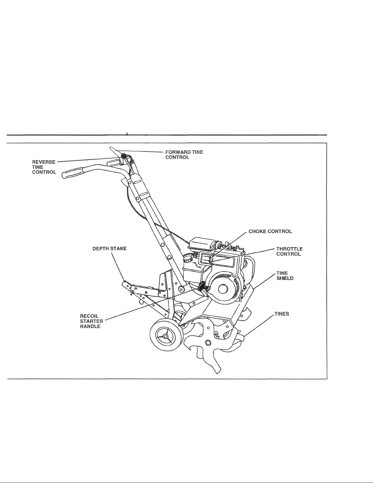
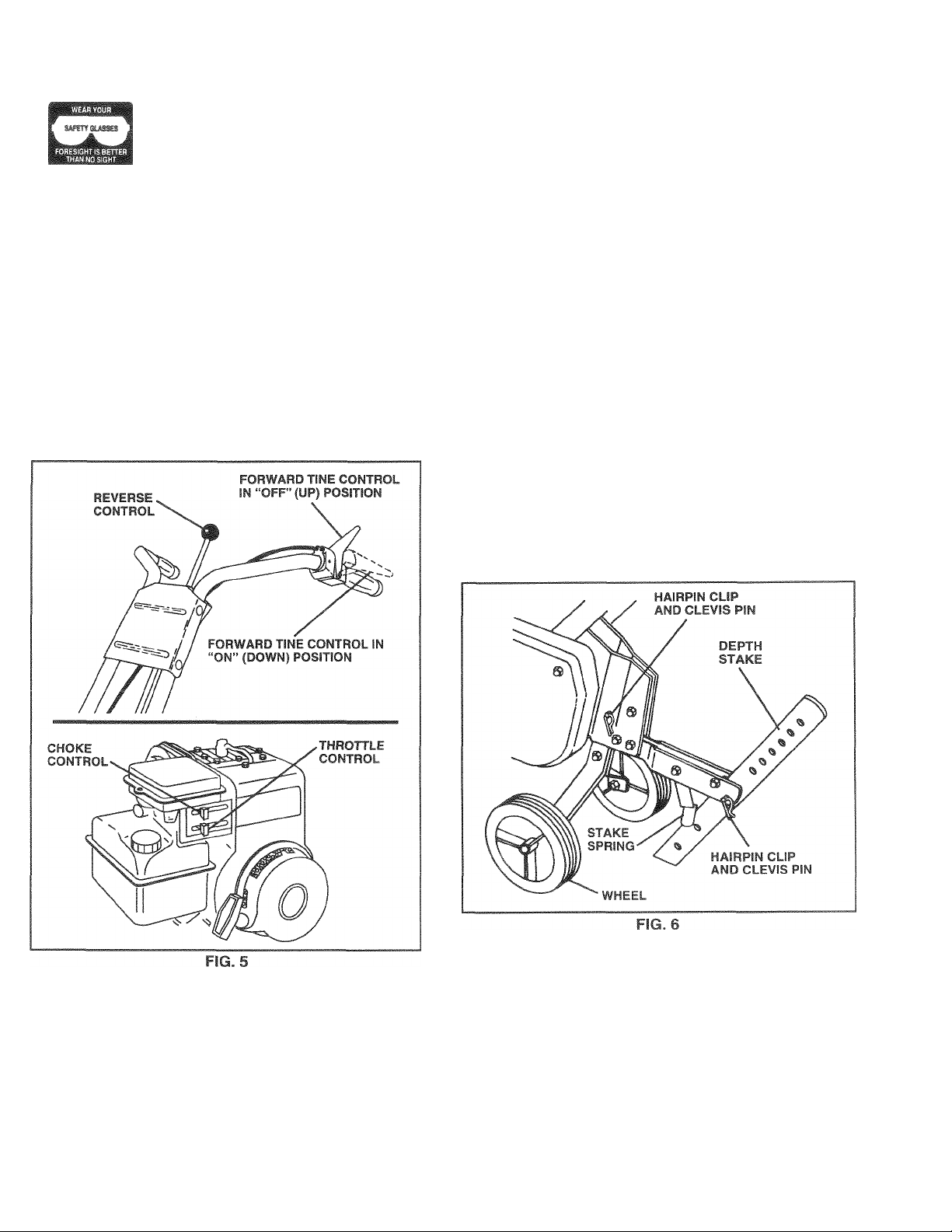
•ORWARD TINE CONTROL - Engages tines in forward CHOKE CONTROL - Used when starling a cold engine,
iirection. DEPTH STAKE - Controls forward speed and the depth at
lEVERSE TINE CONTROL - Engages tines in reverse which the tiller will dig.
Section. RECOIL STARTER HANDLE - Used to start the engine.
'HROTTLE CONTROL - Controls engine speed.
Page 8
OPERATION
The operation of any tiller can resuit ¡n foreign objects thrown into the eyes, which can
result in severe eye damage. Always wear safety glasses oi eve shields before starting
foyr tiller and while tilling, #«? recommend n wide vision safety mask for over spectacles
or standard safety glasses.
HOW TO USE YOUR TILLER
Know how to operate all controls before adding fuel and oil
or attempting to start engine.
STOPPING (See Fig. 5)
TINES
• Release forward tine control to stop forward move
ment.
• Release reverse tine control to stop reverse move
ment.
ENGINE
• Move throttle control to “STOP” position.
• Never use choke to stop engine.
TILLING
The speed and depth of tilling is regulated by the position
of the depth stake and wheel height.
The depth stake should always be below the wheels for
digging. It serves as a brake to slow the tiller’s forward
motion to enable the tines to penetrate the ground. Also,
the more the depth stake is lowered into the ground the
deeper the tines.wiil dig.
DEPTH STAKE (See Fig. 6)
Adjust depth stake by removing the hairpin clip and clevis
pin. Change depth stake to desired position. Replace the
clevis pin and hairpin clip.
• For normal tilling, set depth stake at the second or third
hole from the top.
WHEELS (See Fig. 6)
Adjust wheels by removing the hairpin clip and clevis pin.
Change wheel position. Replace the hairpin clip and clevis
pin.
• For normal tilling, setwheeisatthe second orthird hole
from the top.
TINE OPERATION (See Fig. 5)
FORWARD
• Squeeze forward tine control to handle.
REVERSE
• With forward tine control “OFF” (up) position, pull back
and hold reverse tine control.
8
Page 9

OPERATION
TO TRANSPORT
CAUTION: Before lifting or transport
ing, allow tiller engine and muffler to
A
MOUND THE YARD
• Tip depth stake forward until it is held by the stake
spring.
> Push tiller handles down, raising tines off the ground.
> Push or pull tiller to desired location.
GROUND TOWN
> Disconnect spark plug wire.
' Drain fuel tank.
‘ Transport in upright position to prevent oil leakage.
cool. Disconnect spark plug wire. Drain
gasoline from fuel tank.
BEFORE STARTING ENGINE
MPORTANT; BE VERY CAREFUL NOT TO ALLOW DIRT
ro ENTER THE ENGINE WHEN CHECKING OR ADDING
:)IL OR FUEL. USE CLEAN OIL AND FUEL AND STORE
N APPROVED, CLEAN. COVERED CONTAINERS. USE
3LEAN FILL FUNNELS.
=ILL ENGINE WITH OIL (See Fig. 7}
With engine level, remove engine oil filler plug.
Fill engine with oil to point of overflowing. For approxi
mate capacity see “PRODUCT SPECIFICATIONS” on
page 3 of this manual.
Tilt tiller back on its wheels and then re-level.
With engine level, refill to point of overflowing if neces
sary. Replace oil filler plug.
For cold weather operation you should change oil for
easier starting (See “OIL VISCOSITY CHART” in the
Customer Responsibilities section of this manual).
To change engine oil, see the Customer Responsibili
ties section of this manual.
ADD GASOLINE
* Fiil fuai tank IJ.ae fresh cJr.an feguiai unii-adad
ga.soline, (Use o1 leaded gasoline will increase carbe n
and lead oxide deposi*:-, and reduce valve life i
IMPORTANT; WHEN OPERATING Iff TEMPERATURES
BELOW 32 FI0"C), USE FRESH. GLEAN WINTER GRADE
GASOLINE TO HELP 'NS'JRE GOOD COLD WEATHER
STARTING.
WARNING: Experience indicates that alcohol blended
fuels (called gasohol or using ethanol or methanol) can
attract moisture which leads to separation and formation of
acids during storage. Acidic gas can damage the fuel
system of an engine while in storage. To avoid engine
problems, the fuel system should be emptied before
storage of 30 days or longer. Drain the gas tank, start the
engine and let it run until the fuel lines and carburetor are
empty. Use fresh fuel next season. See Storage section
of this manual for additional information. Never use engine
or carburetor cleaner products in the fuel tank or permanent
damage may occur.
CAUTION: Fill to within 1/2 inch of top
of fuel tank to prevent spills and to
A
allow for fuel expansion. If gasoline is
accidentally spilled, move machine
away from area of spill. Avoid creating
any source of ignition until gasoline
vapors have disappeared.
Do not overfill. Wipe off any spilled oil
or fuel. Do not store, spill or use gaso
line near an open flame.
TO START ENGINE (See Fig. 8)
CAUTION: Keep tine control in “OFF”
A
When starting engine for the first time or if engine has run
out of fuel, it will take extra pulls of the recoil starter to move
fuel from the tank to the engine.
• Make sure spark plug wire is properly connected.
• Place throttle control in “FAST” position.
• Move choke control to full “CHOKE” position. Grasp
recoil starter handle with one hand and grasp tiller
handle with other hand. Pull rope out slowly until
engine reaches start of compression cycle (rope will
pull slightly harder at this point).
• Pull recoil starter handle quickly. Do not let starter
handle snap back against starter. Repeat if necessary.
• If engine tires but does not start, move choke control to
half choke position. Pull recoil starter handle until
engine starts.
• When engine starts, slowly move choke control to
“RUN” position as engine warms up.
position when starting engine.
Page 10

OPERATION
NOTE; A warm engine requires less choking to 'jiari.
• Pove throttP tr*ntro! tu desired running piwitior;
» Ailow engine fo warm up for a few rriinutes before
engaging tine?
NOTE: If a1 a riign altitude (.lOOO feet) or in cold tempera-
ture-b (beiow 32' F). She carboreior fuel inixture may need to
be adjusted for best engine performance See "TO AD
JUST CARBURETOR" in the Sen/ice and Adjustments
section of this manual.
NOTE: If engine does not start, see troubleshooting points.
Tilling is digging into, ii'ming over, and breaking up
packed soif before planting loose, unpacked sr.il
helps ioul Gi'owtfi Best tilling depth is 4' 6^ AJillerwJI
also clear the soil of unwarited vegetaticn. The deccmposition of this vegetable matter enriches the soil
Depending on the citmate (rainfall and v/ind) 4 may be
advisable to till the soil at the end of the growing season
to furthe' cord'iio'^ the soil,
Soil conditions are important for propertilling. Tines will
not readily penetrate dry, hard soil which may contrib
ute to excessive bounce and difficult handling of your
tiller. Hard soil should be moistened before tilling;
however, extremely wet soil will “ball-up” or clump
during tilling. Wait until the soil is less wet in order to
achieve the best results. When tilling in the fall, remove
vines and long grass to prevent them from wrapping
around
You will find tilling much easier if you leave a row
untilled between passes. Then go back between tilled
rows. (See Fig. 9) There are two reasons for doing this.
First, wide turns are much easier to negotiate than
about-faces. Second, the tiller won’t be pulling itself,
and you, toward the row next to it.
Set depth stake and wheel height for shallow tilling
when working extremely hard soil or sod. Then work
across the first cuts at normal depth.
the tine shaft and slowing your tilling operation.
BREAKING IN YOUR TILLER
Break-in your belt(s), pulleys and tine control before you
actually begin tilling.
• Start engine, tip tines off ground by pressing handles
down and engage tine control to start tine rotation.
Allow tines to rotate for five minutes.
* Check tine operation and adjust if necessary. See
‘TINE OPERATION CHECK” in the Service and Ad
justments section of this manual.
TILLING HINTS
CAUTION: Until you are accustomed to
handling your tiller, start actual field
A
T0 help tiller move forward, lift up the handles slightly (thus
lifting depth stake out of ground). To slow down the tiller,
press down on handles.
If you are straining or tiller is shaking, the wheels and depth
stake are not set properly in the soil being tilled. The proper
setting of the wheels and depth stake is through trial and
error and depends upon the soil condition. (The harder or
wetter the ground, the slower the engine and tine speed
needed. Underthese poorconditions.atfast speed the tiller
will run and jump over the ground).
A properly adjusted tiller will dig with little effort from the
operator.
use with throttle in slow position.
CULTIVATING
Cultivating is destroying the weeds between rows to pre
vent them from robbing nourishment and moisture from
the plants. At the same time, breaking up the upper layer
of soil crust will help retain moisture in the soil. Best
digging depth is T'-3".
• You will probably not need to use the depth stake.
Begin by tipping the depth stake forward until it is held
by the stake spring.
» Cultivate up and down the rows at a speed which will
allow tines to uproot weeds and leave the ground in
rough condition, promoting no further growth of weeds
and grass (See Fig. 10).
Page 11

CUSTOMER RESPONSIBILITIES
MAINTENANCE
SCHEDULE
/ip / ^ /Co / Co /
/ ^ / £> / / <r /
/> / ^
FILL IN DATES
AS YOU COMPLETE
REGULAR SERVICE
Check Engine Oil Level
Change Engine Oil
Oil Pivot Points
Inspect Spark Arrester / Muffler
Inspect Air Screen
Clean or Replace Air Cleaner Cartridge
Clean Engine Cylinder Fins
Replace Spark Plug
1 - Change more often when operating under a heavy load or in high ambient temperatures.
2 - Sen/ice more often when operating in dirty or dusty conditions.
/S'/x/^/sy
/£/#/f/m SERVICE DATES
✓
✓
<2
✓
✓
GENERAL RECOMMENDATIONS
he warranty on this tiller does not cover items that have
>een subjected to operator abuse or negligence. To
eceive full value from the warranty, operator must mainain tiller as instructed in this manual.
Some adjustments will need to be made periodically to
roperly maintain your tiller.
dl adjustments in the Service and Adjustments section of
lis manual should be checked at least once each
eason.
Once a year you should replace the spark plug, clean
or replace air filter, and check tines and belts for wear.
A new spark plug and clean air filter assure proper airfuel mixture and help your engine run better and last
longer.
✓
✓ 2
✓
✓
LUBRICATION CHART
lEFORE EACH USE
Check engine oil level.
Check tine operation.
Check for loose fasteners.
.UBRICATION
:eep unit well lubricated (See “LUBRICATION CHART”).
ARM
* SAE 30 OR 10W-30 MOTOR OIL
** REFER TO CUSTOMER RESPONSIBILITIES “ENGINE” SECTION
11
Page 12

A
CUSTOMER RESPONSIBILITIES
Disconnect spark plug wire before performing any maintenance (except carburetor adjustment) to prevent
accidental starting of engine.
Prevent fires! Keep the engine free of grass, leaves, spilled oil, or fuel. Remove fuel from tank before tipping
unit for maintenance. Clean muffler area of all grass, dirt, and debris.
Do not touch hot muffler or cylinder fins as contact may cause burns.
ENGINE
LUBRICATION
Use only high quality detergent oil rated with API service
classification SF, SG or SH. Select the oil’s SAE viscosity
grade according to your expected temperature.
SAE VISCOSITY GRADES
-20" 0°
°F
°C -30"
NOTE: Although multi-viscosity oils (5W-30,10W-30,etc.)
improve starting in cold weather, these multi-viscosity oils
will result in increased oil consumption when used above
32°F (0°C). Check your engine oil level more frequently to
avoid possible engine damage from running low on oil.
Change the oil after every 25 hours of operation or at least
once a year if the tiller is not used for 25 hours in one year.
Check the crankcase oil level before starting the engine
and after each five (5) hours of continuous use. Add SAE
30 motor oil or equivalent. Tighten oil filler plug securely
each time you check the oil level.
20° -10° 0° 10° 20° 30° 40°
TEMPERATURE RANGE ANTICIPATED BEFORE NEXT OIL CHANGE
30° 32° 40°
FIG. 11
60° 80° 100°
AIR CLEANER |5ee Fig. 13)
Service aircleanercartridge every twenty-five hours, more
often if engine is used in very dusty conditions.
Loosen air cleaner screws, one on each side of cover.
Remove air cleaner cover.
Carefully remove air cleaner cartridge. Be careful. Do
not allow dirt or debris to fail into carburetor.
Clean by tapping gently on a flat surface.
If very dirty or damaged, replace cartridge.
Clean and replace cover. Tighten screws securely.
CAUTION: Petroleum solvents, such
as kerosene, are not to be used to clean
A
cartridge. They may cause deteriora
tion of the cartridge. Do not oil car
tridge. Do not use pressurized air to
clean or dry cartridge.
TO CHANGE ENGINE OIL (See Figs. 11 and 12)
Determine temperature range expected before oil change.
All oil must meet API service classification SF, SG or SH.
® Be sure tiller is on level surface.
• Oil will drain more freely when warm.
• Catch oil in a suitable container.
® Remove drain plug.
• Tip tiller forward to drain oil.
• After oil has drained completely, replace oil drain plug
and tighten securely.
• Remove oil filler plug. Be careful not to allow dirt to
enter the engine.
• Refill engine with oil. See “CHECK ENGINE OIL
LEVEL” in the Operation section of this manual.
COOLING SYSTEM (See Fig. 14)
Your engine is air cooled. For proper engine performance
and long life keep your engine clean.
• Clean air screen frequently using a stiff-bristled brush.
• Remove blower housing and clean as necessary,
• Keep cylinder fins free of dirt and chaff.
Page 13

Do not op6rat6 tiiter without mufflsr. Do not tampor with
3xhausi system. Damaged mufflers or spark arresters
'iould create a fire hazard. Inspect periodically and replace
f necessary. If your engine is equipped with a spark
rm K* < |•■pм ,} ruth r'.fr,/ M hoit* i ■>!
!t III 1 ( 'll L 1 t I 111>1 D»j. i II I i| i
PARK F»LIIG
epir''€ ..pirr pk 4« Jtdw qciMriqj* jchilin' a'cr
!i attcreveiySOhr.umr.timt whitfifc\tn jriieifnD Dpaik
)'uqtypeai‘dyap'etrinq a« -hjwsiin ’^HC'DUt i JFD'I
-Ik Al iOND” on pjqf > nt iti ^ tnanual
SERVICE AND ADJUSTMENTS
CAUTION: Disconnect spark plug wire from spark plug and place wire where it cannot come into
A
TILLER
rO ADJUST HANDLE HEIGHT (See Fig. 15)
-actory assembly has provided lowest handle height. Se3ct handle height best suited for your tilling conditions,
iandie height will be different when tiller digs into soil.
If a higher handle height is desired, loosen the four nuts
securing handle panel to engine brackets.
Slide handle panel to desired location.
Tighten the four nuts securely.
contact with plug.
- hAr* Mi\ ->.1« sN
Your transmissiori is sealed and will not require lubrication
unless serviced.
r; f^hmu
• Clean engine, wheels, finish, etc. of ali foreign matter.
' ^ “plirtlhl* id ^ n|/‘f I lillM
uli!. eic.
•* f r.it“ > paif>i'd I'd.n ' wrh . -rrmcfive tvf»f wj.
“Zed ! .rrinmO j I1.4 - 4 M-R . dfshjfcur
unit unit, .tilt riiufflt r rir filtc 1 anil c jibitw tor irc »rwi-r-ci
ioketpwatcrout Water.rieiigi.i» 1 diiroaUiti la. Iiortt.ied
engine me.
MID-WIDTH TILLING - 24" PATH (See Fig. 17)
• Assemble holes “A” in tine hubs to holes “C” in tine
shaft.
■|NE ARRANGEMENT
'ouroutertinescan be assembled in several different ways
3 suit your tilling or cultivating needs.
CAUTION: Tines are sharp. Wear
gloves or other protection when han
A
iORMAL TILLING - 26" PATH (See Fig. 16)
Assemble holes “A” in tine hubs to holes “B” in tine
shaft.
dling tines.
FIG. 17
NARROW TILLING/CULTIVATING -12-3/4" PATH (See
Fig.JS)
• Hemove outer tines.
FIG. 18
NOTE: When reassembling outer tines, be sure right tine
assembly (marked “R”) and left tine assembly (marked “L”)
are mounted to correct side of tine shaft.
13
Page 14

SERVICE AND ADJUSTMENTS
TINE OPEhAliON CHECK (See Fig. 19|
WARNING: Ossconneci spark plug wire
from spark plug to prevent starting
A
For propertsi^c cperaticn. 'cr.vara tioe centro! leve*' must to
against control boay and ail slack removed from inner wire
of control cable when control is in the “OFF” I up) position
if iever and cable are loose, loosen cable clip at lower end
of cable. Pull up on cable to remove slack, without
extending spring on end of cable, and retighten cable clip.
FINAL CHECK “OFF” POSITION
With tine control “OFF” (up), push down on handle to
raise tines off the ground.
Slowly pull recoil starter handle while observing tines.
Tines should not rotate.
If tines rotate, inner wire of control cable is too tight
which is extending lower spring and engaging tines.
Loosen cable clip and push down on cable only enough
to relieve spring tension. Tighten cable clip.
Recheck in “OFF” position and adjust if necessary.
FINAL CHECK “ON” POSITION
With tine control “ON” (held down to handle) push down
on handle to raise tines off the ground.
Slowly pull recoil starter handle while observing tines.
Tines should rotate forward.
If tines do not rotate, inner wire of control cable is too
loose. Loosen cable clip and puli cable up to remove
slack and retighten clip.
Recheck in “ON” position and adjust if necessary.
NOTE: If “ON" position check required adjustment, re
check “OFF” position adjustment to insure tines do not
rotate when control is “OFF’ (up).
while checking tine operation.
TO REMOVE BELT GUARD (See Fig. 20)
• Remove t*f- (¿K.'ifi arid wuihers frotfi vuit -„f belt
guard.
• Looser. ('3c not reoi.jve i tine vhielcl nut on underside of
tine shield.
• Pul! belt yuami cut arto away ‘rom unit
» Reptece belt guard by reversing above oroceaure. Be
sure sloi m bottom of belt guard is under head of tine
shield bolt and all nuts are tightened securely.
TO REPLACE V-BELTS (See Figs. 21 and 22)
Replace V-belts if they have stretched considerably or if
they show cracks or frayed edges. There are two (2) Vbelts - forward (inside) and reverse (outside).
Belt guard must be removed to service belts. See “TO
REMOVE BELT GUARD” in this section of manual.
NOTE: Observe carefully routing of both belts and location
of ail belt guides before removing belts.
BELT REMOVAL
• Remove reverse idler pulley from idler arm.
• Remove reverse (outside) V-belt.
• Remove forward (inside) V-belt from transmission pul
ley first and then from engine pulley.
BELT REPLACEMENT
• Install new forward (inside) V-belt to engine pulley first
then to transmission pulley. Be sure belt is positioned
on inside groove of both pulleys, inside all belt guides
and rests on idler pulley.
• Before installing reverse (outside) V-belt, turn belt
“inside out”. Twist so wide, flat surface of belt is to
inside.
• Wrap V-belt around reverse idler pulley and reas
semble idler to idler arm. Tighten securely. Be sure
belt is between reverse idler pulley and idler arm pin.
• Install belt to outside groove of transmission pulley. Be
sure belt is inside all belt guides and rests on outside
groove of engine pulley.
CHECK TINE OPERATION
• See “TINE OPERATION CHECK”
manual.
REPLACE BELT GUARD
in this section of
Page 15

SERVICE AND ADJUSTMENTS
FIG. 22
15
Page 16

STORAGE
iiiinedk tuly ,>it( ti. /,
£eflS:<’*n or if t IH U ’It «VI
i.AtJTION Never store the niter with
gasoline In the tan^ inside 3 byilding
where fumes may reach an open flame
A
or spark. Allow the engine to coo!
before storing in any enclosure.
r tlllr I f.i| . to lUt f no • •' in
ri'd bP hSbd foi jO J- u. moT
TILLER
» Clean entire tiller (See “CLEANING” in the Customer
Responsibilities section of this manual).
• Inspect and replace belts, if necessary (See belt re
placement instructions in the Service and Adjustments
section of this manual).
• Lubricate as shown in the Customer Responsibilities
section of this manual.
• Be sure that all nuts, bolts and screws are securely
fastened. Inspect moving parts for damage, breakage
and wear. Replace if necessary.
® Touch up all rusted or chipped paint surfaces; sand
lightly before painting.
ENGINE
FUEL SYSTEM
IMPORTANT: IT IS IMPORTANT TO PREVENT GUM
DEPOSITS FROM FORMING IN ESSENTIAL FUEL
SYSTEM PARTS SUCH AS THE CARBURETOR, FUEL
FILTER, FUEL HOSE, OR TANK DURING STORAGE.
ALSO, EXPERIENCE INDICATES THAT ALCOHOL
BLENDED FUELS (CALLED GASOHOL OR USING
ETHANOL OR METHANOL) CAN ATTRACT MOISTURE
WHICH LEADS TO SEPARATION AND FORMATION OF
ACIDS DURING STORAGE. ACIDIC GAS CAN DAMAGE
THE FUEL SYSTEM OF AN ENGINE WHILE IN STORAGE.
® Drain the fuel tank.
• Start the engine and let it run until the fuel lines and
carburetor are empty.
• Never use engine or carburetor cleaner products in the
fuel tank or permanent damage may occur.
• Use fresh fuel next season.
NOTE: Fuel stabilizer is an acceptable alternative in
minimizing the formation of fuel gum deposits during stor
age. Add stabilizer to gasoline in fuel tank or storage
container. Always follow the mix ratio found on stabilizer
container. Run engine at least 10 minutes after adding
stabilizer to allow the stabilizer to reach the carburetor. Do
not drain the gas tank and carburetor if using fuel stabilizer.
ENGINE OIL
Drain oil (with engine warm) and replace with dean oil.
(See “'ENGINE' in ihe Custunier Responsibilities set iioti of
this manual).
CYLINDER
Remove spark plug.
Pour 1 ounce (29 ml) of oil through spark plug hole into
cylinder.
Pull starter handle slowly several times to distribute oil.
Replace with new spark plug.
OTHER
Do not store gasoline from one season to another.
Replace your gasoline can if your can starts to rust.
Rust and/or dirt in your gasoline will cause problems.
If possible, store your unit indoors and cover it to give
protection from dust and dirt.
Cover your unit with a suitable protective cover that
does not retain moisture. Do not use plastic. Plastic
cannot breathe which allows condensation to form and
will cause your unit to rust.
IMPORTANT: NEVER COVER TILLER WHILE ENGINE
AND EXHAUST AREAS ARE STILL WARM.
16
Page 17

TROUBLESHOOTING POINTS
PROBLEM CAUSE
Will not start 1. Out of fuel.
2. Engine not “CHOKED” properly.
3. Engine flooded.
4. Ditty air ciearier.
5. Water in fuel.
6. Clogged fuel tank.
7. Loose spark plug wire.
8. Bad spark plug or Improper gap.
9. Carburetor out of adjustment.
■lard to start 1. Throttle control not set properly.
2. Dirty air cleaner.
3. Bad spark plug or improper gap.
4. Stale or dirty fuel.
5. Loose spark plug wire.
6. Carburetor out of adjustment.
.OSS of power
1. Engine is overloaded.
2. Dirty air cleaner.
3. Low oil level/dirty oil.
4. Faulty spark plug.
5. Oil in fuel.
6. Stale or dirty fuel.
7. Water in fuel.
8. Clogged fuel tank.
9. Spark plug wire loose.
10. Dirty engine air screen.
11. Dirty/clogged muffler.
12. Carburetor out of adjustment.
13. Poor compression.
CORRECTION
1. Fill fuel tank.
2. See “TO START ENGINE” in the Operation section.
3. Wait several minutes before attempting to start.
4. Clean or replace air cleaner cartridge.
5. Drain fuel tank and carburetor, and refill tank with
fresh gasoline.
6. Remove fuel tank and clean.
7. Make sure spark plug wire is seated properly on plug.
8. Replace spark plug or adjust gap.
9. Make necessary adjustments.
1. Place throttle control in “FAST” position.
2. Clean or replace air cleaner cartridge.
3. Replace spark plug or adjust gap.
4. Drain fuel tank and refill with fresh gasoline.
5. Make sure spark plug wire is seated properly on plug.
6. Make necessary adjustments.
1. Set depth stake and wheels for shallower tilling.
2. Clean or replace air cleaner cartridge.
3. Check oil level/change oil.
4. Clean and regap or change spark plug.
5. Drain and clean fuel tank and refill, and clean
carburetor.
6. Drain fuel tank and refill with fresh gasoline.
7. Drain fuel tank and carburetor, and refill tank with
fresh gasoline.
8. Remove fuel tank and clean.
9. Connect and tighten spark plug wire.
10. Clean engine air screen.
11. Clean/replace muffler.
12. Make necessary adjustments.
13. Contact an authorized service center/department.
Ingine overheats 1. Low oil level/dirty oil.
2. Dirty engine air screen.
3. Dirty engine.
4. Partially plugged muffler.
5. Improper carburetor adjustment.
ixoessive bounce/
1. Ground too dry and hard.
iifficult handling
2. Wheels and depth stake incorrectly adjusted.
Soil bails up or clumps
ingine runs but tiller
lon’t move
ingine runs but labors
/hen tilling
1. Ground too wet.
1. Tine control is not engaged.
2. V-belt not correctly adjusted.
3. V-belt is off pulley(s).
1. Tilling too deep.
2. Throttle control not properly adjusted.
3. Carburetor out of adjustment.
1. Check oil level/change oil.
2. Clean engine air screen.
3. Clean cylinder fins, air screen, muffler area.
4. Remove and clean muffler.
5. Adjust carburetor to richer position.
1. Moisten ground or wait for more favorable soil
conditions.
2. Adjust wheels and depth stake.
1. Wait for more favorable soil conditions.
1. Engage tine control.
2. Inspect/adjust V-belt.
3. Inspect V-belt.
1. Set depth stake for shallower tilling.
2. Check throttle control setting.
3. Make necessary adjustments.
17
Page 18

REPAIR PARTS
HANDLE ASSEMBLY
TILLER - - MODEL NUMBER CHDF550D
KEY
NO.
10
11 73220500
12
13
1416674A150428
PART
NO.
131268X428
1
72140512
2
9266R
3
4 153138
73680500
5
19111116
6
19121414
7
74760516
8
74760512
9
10040500
98000129
72140506
153139
DESCRIPTION
Bracket, Handle
Bolt, Carriage 5/16-18 UNC x 1-1^
Grip, Handle 19
Handle, L.H.
Locknut, Crown 5/16-18
Washer 11/32 x 11/16 x 16 Ga.
Washer 3/8 x 7/8 x 14 Ga.
Bolt, Hex Hd. 5/16-18 X 1 24 2613J
Bolt, Hex Hd 5/16-18x3/4
Washer, Lock 5/16 26
Nut, Hex 5/16-18
Nut, Flanged 5/16-18 28
Bolt, Carriage 5/16-18 x 3/4 Gr. 5
Panel, Handle
Handle, R.H.
KEY
NO.
17
18
20
21
22
23
25
27 76020308
29
NOTE: All component dimensions are given in U.S. inc
18
PART
NO.
106932X Knob, Control, Reverse
3066J
151229
154805 Pin, Pivot
12000027
101248K Rod, Reverse, Upper
1778E
19131316
76020412 Pin, Cotter 1/8 X 3/4
19131312
12000059
1 inch = 25.4 mm
DESCRIPTION
Cable, Control, Tine
Lever, Control, Tine
Ring, Klip
Pin, Retaining
Rod, Reverse, Lower
Washer 13/32 x 13/16 x 16 Ga.
Pin, Cotter 3/32 X 1/2
Washer 13/32 x 13/16 x 12 Ga.
Retaining, Ring
Page 19

BEPAm PARTS
TILLER - - MODEL NUMBER CHDF550D
BELT GUARD AND PULLEY ASSEMBLY
CEY PART
JO. NO.
1 159268
2 9484R
3 86777
4 74610812
5 73220600
6 19131316
7 2009J
8 1271 SOX
9 74760628
10 156705X428
11 19091016
12 104213X
13 72140406
14 133035
15 2614J
16 12000028
17 2649M
18 151236
DESCRIPTION
Assembly, Bracket, Belt Guard
Clip, Cable
Screw, Hex, Washer Hd., Slotted,
Thd. Cutting #10-24 x 1/2 Type D
Bolt, Hex 1/2-20x3/4
Nut, Hex 3/8-16
Washer 13/32 x 13/16 x 16 Ga.
Pulley, Idler, Reverse
Assembly, Arm, Reverse Idler
Bolt, Hex 3/8-16 X 1-3/4
Guard, Belt
Washer 9/32 x 5/8 x 16 Ga.
Nut, Cap 1/4-20
Bolt, Carriage 1/4-20 x 3/4
V-Belt (Forward Motion)
V-Belt (Reverse)
Ring, Retainer
Key, Square
Pulley, Flat, Trans.
32
iB
KEY PART
NO. NO.
19 110550X
12000036
20
21 73350600
22
161806
23 162290
74760620
24
25 106968X
26 73350500
27 73220400
28 10040400
29 109227X
23200404
30
31 101189L
32
151223
33 73510400
34 19091416
NOTE: All component dimensions given in U.S. inches.
1 inch = 25.4 mm
DESCRIPTION
Bolt, Belt Guard
Ring, Klip
Nut, Hex, Jam 3/8-16
Pulley, Idler
Arm, Idler
Bolt, Hex 3/8-16 X 1-1/4
Shaft, Idler Arm
Nut, Hex, Jam 5/16-18
Nut, Fin Hex 1 /4-20
Washer LK Hvy Helical 1/4
Pad, Idler
Screw, Set, Socket, Headless
C.P. 1/4-20 X 1 /4
Sheave, Engine
Pulley, V-Groove, Trans.
Nut Keps Hex 1/4-20
Washer 9/32 x 7/8 x 16 Ga.
19
Page 20

REPAIR PARTS
TILLER - - MODEL NUMBER CHDF550D
WHEEL AND DE-^1 T IT^rt ASSEMBLY
KEY
NO.
10
11
121374760524
PART
NO.
1 9194R
2
74760520
3 74760512
4
73220500 Nut, Hex 5/16-18
5 10040500 Washer, Lock 5/16
6
73800600
7 4921H Clip, Hairpin
8 1952J Support, Depth Stake, R.H.
9
122233X
326J
74780628
1951J
DESCRIPTION
Pin, Clevis
Bolt, Hex 5/16-18x1-1/4
Bolt, Hex 5/16-18x3/4
Locknut, w/washer 3/8-16
Stake, Depth
Pin, Clevis
Bolt, Hex, Fin 3/8-16x1-3/4
Bolt, Hex 5/16-18 X 1-1/2 Gr. 2
Support, Depth Stake, L.H.
-'*" y
5/
KEY
NO.
14
15
16
17
18
19
20
21
22
NOTE: All component dimensions given in U.S. incr
PART
NO.
120958X
5388J
121117X
9188R
19131311
9190R
73680600
74760516
73800500
1 inch = 25.4 mm
DESCRIPTION
Washer
Spring, Stake
Bolt, Shoulder
Wheel
Washer 13/32 x 13/16 x 11 Ga.
Bracket, Wheel
Locknut, Crown 3/8-16
Bolt, Hex 5/16-18 X 1
Locknut, w/insert 5/16-18
20
Page 21

REPAIR PARTS
TINE ASSEMBLY
TILLER - - MODEL NUMBER CHDF550D
CEY
iO.
1
156934
2 3146R
3
156932
PART
NO.
DESCRIPTION
Tine, Outer, R.H.
Clip, Hairpin
Tine, Inner, R.H.
21
KEY PART
NO. NO.
4 156931
5 156933
6 4929H
DESCRIPTION
Tine, Inner, L.H.
Tine, Outer, L.H.
Pin, Clevis
Page 22

REPAIR PARTS
TRANSMISSION
TILLER - - MODEL NUMBER CHDF550D
KEY
NO.
PART
NO.
1 74760524
2
74780652 Bolt, Hex, Fin 3/8-16x3-1/4
3
19131311 Washer 13/32x13/16x11
DESCRIPTION KEY
Bolt, Hex 5/16-18 X 1-1/2 Gr. 2
5 73800600 Locknut, Hex, w/washer 3/8-16
6 9057R428 Shield, Tine
7
1949J Bracket, Engine, R.H.
8 1948J Bracket, Engine, L.H.
9
10040500
10
732205G0
11
74760544
12 151222
Washer, Lock 5/16
Nut, Hex 5/16-18
Bolt, Hex 5/16-18x2-3/4
Transmission
PART
NO.
13 19171616
NO.
DESCRIPTION
Washer 17/32 x1 x 16 Ga.
14 9173R Spacer, Split
15 73510500 Nut, Keps 5/16
19091412 Washer 9/32 x 7/8 x 12 Ga.
16
17 19092016
Washer 9/32 x 1-1/4 x 16 Ga.
18 10040400 Washer, Lock 1/4
74610412
19
20 Engine, Briggs and Stratton, Model
NOTE: All component dimensions given in U.S. inches.
1 inch = 25.4 mm
Bolt, Hex 1/4-28 x 3/4 Gr. 5
No 137202
22
Page 23

REPAIR PARTS
DECALS
TILLER - - MODEL NUMBER CHDF550D
KEY
NO.
PART
NO.
1 157377
2 157380
157378
3
4 121753X
110614X
5
6 110612X
271948 Decal, Briggs & Stratton
7
120076X Decal, Warning, Rotating Tines
8
157381 Decal, Hvy Duty
9
DESCRIPTION
Decal, Logo
Decal, Logo
Decal, HP, Reverse
Decal, Reverse, Tine Control
Decal, Hand Placement
Decal, Caution
10 273721 Decal, 5 HP
162384 Decal, Warning Till
11
164784 Manual, Owner’s (English)
164785
Manual, Owner’s (French)
23
Page 24

Poutan
 Loading...