

Page 1
II
OPERATO °$
UAL
SELF-PROPELLED ROTARY
LAWN MOWER
Assembmy
Operation
o Maintenance
• Service and Adjustments
o Storage
o Troubleshooting
_,WARNING: This lawn mower isequippedwith an internal combustion engine and
should not be used on or near any unimproved forest-covered, brush-covered or
grass-covered land unless the engine's exhaust system is equipped with a spark
arrester meeting applicable local or slate laws (ifany). Ifa spark arreeter is used, it
should be maintained in effective working order by the operator
In Ihe state of California the above is required by law (Section 4442 of the California
Public Resources Code). Other states may have similar laws, Federal laws apply
on federal lands_ A spark arrester for the muffler is available through your nearest
authorized service center.
193733 Rev. 9 09.16.10 BY Printed in U.SoA.
Page 2
SafetyRules......................2-3 Maintenance.............22-26Storage..........................33-34
Assembly...........................5-B Serviceand Troubleshooting..............35-36
Operation......................9-21 Adjustments..................27-32
IMPORTANT"Thiscuttingmachineiscapableofamputatinghandsandfeetandthrowingob-
jects_Failuretoobservethefollowingsafelyinstructionscouldresultinserious injury or death,
_Look for this symbol to point out impor_ ', Do not pull mower backwards unless
tant safely precaulions. It means absolutely necessary. Always look down
CAUTIONII! BECOME ALERTI!I
YOUR SAFETY IS INVOLVED_
_, WARNING: In order to prevent accidental
starting when selting up, transporting, ad-
justing or maklng repairs, always disconnect
spark plug wire and place wire where itcannot
come in contact with plug
_,WARNING: Engine exhaust, some of its
constituents, and certain vehicle compo-
nents contain or emit chemicals known to
the State of California to cause cancer and
birth defects or other reproductive harm.
_,WARNING: Battery posts, terminals and
related accessories contain lead and lead
compounds, chemicals known to the State
of California to cause cancer and birth
defects or other reproductive harm_ Wash
hends after handling,
_,CAUTION: Muffler and
olher engine parts become
extremely hot during
operation and remain hot
after engine has stopped
To avoid severe burns on
contact, stay away from these areas,,
I. GENERAL OPERATION
- Read, understand, and follow all
instructions on the machine and in the
manual(s) before starting, Be thoroughly
lamiliar with the controls and the proper
use of the machine before starting.
- Do not put hands or feet near or under
rotatingpads. Keep clear of the dis-
charge opening at all times.,
° Only allow responsible individuals, who
are familiar with the instructions, to oper-
ate the machine.
• Clear the area of objects such as rocks,
toys, wire, bones, sticks, etc., which
could be picked up and thrown by blade,
° Be sure the area is clear of other people
before mowing, Stop machine if anyone
enters the area°
° Do not operate the mower when bare-
foot or wearing open sandals. Always
wear substantial foot wear.
and behind before and while moving
backwards.
,, Never direct discharged material toward
anyOne. Avoid discharging material against
a wall or obstruction. Material may richo-
chet back toward the operator Stop the
blade when crossing gravel surfaces
• Do not operate the mower without
proper guards, plates, grass catcher or
other safety protective devices in place
• See manufacturer's instructions for
proper operation and installation of
accessories. Only use accessories ap-
proved by the manufacturer..
• Stop the blade(s) when crossing gravel
drives, walks, or roads,
° Stop the engine (motor) whenever you
leave the equipment, before cleaning the
mower or unclogging the chute.,
° Shut the engine (motor) off and watt until
Ihe blade comes to complete stop before
removing grass catcher.,
• Mow only in daylight / good artificial lighL
. Do not operate the machine while under
the influence of alcohol or drugs,,
° Never operate machine in wet grass,
Always be sure of your footing: keep a
firm hold on the handle; walk, never run,
° Disengage the self-propelled mech-
anism or drive clutch on mowers so
equipped before startfng the engine.
. Ifthe equipment should start to vibrate
abnormally, stop the engine (motor) and
check immediately for the cause, Vibra_
lion is generally a warning of trouble.
• Always wear safety goggles orsafetyglass-
eswith side shieldswhen operating mowen
II, SLOPE OPERATION
Slopes are a major factor related to slip &
fall accidents which can result in severe in-
jury.,All slopes require extra caution,, If you
feeDuneasy on a slope, do not mow it
DO:
• Mow across the face of slopes: never
up and down. Exercise extreme caution
2 when changing direction on slopes_
Page 3
• Removeobstacles(rocks,treelimbs,etc,,)
• Watchforholes,ruts,orbumps_Tall
grasscanhideobstacles
DO NOT:
,, Do not trim near drop-offs, ditches or
embankments° The operator could lose
footing or balance°
• Do not trim excessively steep slopes,
o Do not mow on wet grass, Reduced foot-
ing could cause slipping,,
III. CHILDREN
Tragic accidents can occur if the operator is
not alert to thepresence of children, Children
are often attracted to the machine and the
mowing activity, Neverassume that children
will remain where you last saw them°
,, Keep children out of the trimming area
and under the watchful care of another
responsible adult,
,, Be alert and turn machine off if children
enter the area°
• Before and while walking backwards,
look behind and down for small children,
. Neveral!ow children to operate the mowero
. Use extra care when approaching blind
corners, shrubs, trees, or other obiects
that may obscure vision_
IV. SAFE HANDLING OF GASOLINE
Use extreme care in handling gasollne_
Gasoline is extremely flammable and the
vapors are explosive.
° Extinguish all cigarettes, cigars, pipes
and other sources of ignition°
o Use only an approved container,
° Never remove gas cap or add fuel with
the engine running_ Allow engine to cool
before refueling.
o Never refuel the machine indoors,
° Never store the machine or fuel contain-
er where there is an open flame, spark
or pilot fightsuch as a water heater or on
otherappliances,,
° Never fill containers inside a vehicle, on
a truck or trailer bed with a plastic liner.
Always place containers on the ground
CONGRATULATIONS onyour purchase of a new Lawn Mower, it has been designed, engi-
neered end manufactured togive you the best possible dependablltty and performance.
Should you experience any problems you cannot easily remedy, please contact your
nearest authorized service center, They have competent, well trained technicians and
the proper tools to service or repair this unit,
° Read the SAFETY RULES and this Operator's Manual in its entirety before you at-
tempt to assemble or operate your new lawn mower to insure proper operation and to
prevent injury to yourself and others., Save this manual for future reference.,
o Your new lawn mower has been assembled at the factory with the exception of those
paris left unassembled for shipping purposes. To ensure safe and proper operation
of your lawn mower, all parts and hardware you assemble must be tightened securely,
Use the correct tools as necessary to ensure proper tightness°
,, All parts such as nuts, washers, bolts, etc,, necessary to complete the assembly have
been placed in the parts bag° 3
away from your vehicle before filling,.
,, Remove gas-powered equipment from the
truckortrailerand refuelitonthe ground, tf
this isnot possible, then refuel such equip-
ment with a portable container, rather than
from a gasoline dispenser nozzle.
, Keep the nozzle in conlact with the rim
of the fuel tank or container opening at
all times until fueling is completer Do not
use a nozzle lock-open device.
° If fuel is spilled on clothing, change
clothing immediately,
° Never overfill fuel tank. Replace gas cap
and tighten securely.
V, GENERAL SERVICE
° Never run machine inside a closed area_
. Never make adjustments or repairs with
the engine (molor) running. Disconnect the
spark plug wire, and keep the wire away
from the plug toprevent accidentalstading
• Keep nuts and bolts, especially blade
attachment bolts, tight and keep equip-
ment in good condition.
° Never tamper with safety devices,. Check
their proper operation regularly_
.. Keep machine free ofgrass, leaves,orother
debris build-up, Clean oil or fuel spillage_
Allow machine to cool before storing,
• Stop and Inspect the equipment if you
strike an object., Repair, if necessary,
before restarting.
° Never attempt to make wheel height
adjustments while the engine is running°
• Grass catcher components are subject to
wear, damage, and deterioration, which
could expose moving parts or allow objects
tobethrown. Frequently check components
and replace with manufacturer's recom_
mended parts, when necessary,
• Mower blades are sharp and can cut,
Wrap the blade(s) or wear gloves, and
use extra caution when servicing them,
• Do not change the engine governor set-
ting or overspeed the engine,
o Maintain or replace safety and instruc-
tion labels, as necessary.
Page 4
TO REMOVE LAWN MOWER
FROM CARTON
o Remove all loose parts from carton°
• Remove lawn mower housing wilh care,,
Avoid touching blade under housing_
Always wear gloves or other protection
when working under or lifting mower,,
THINGS TO KNOW BEFORE YOU
ASSEMBLE OR OPERATE YOUR
LAWN MOWER
Do I have a side or rear discharge lawn
mower?
Look for the grass discharge opening on
your mower.. If the opening ison the right
side of the mower housing, itis a side
discharge mower. If the opening isat the
back of the mower housing, it is a rear dis-
charge mower, Only rear discharge lawn
mowers have a grass catcher included
wilh the mower. Approved grass catch-
ers for side discharge mowers may be
purchased from your nearest authorized
dealer.,
Do I have a mulching lawn mower?
Look for the grass discharge opening on
your mower.. Raise the discharge guard
(rear door on rear discharge mowers), If
the opening is closed off by a plate, then
your lawn mower is mulcher ready.. To
convert to a discharging mower, see the
Operation section of this manual.
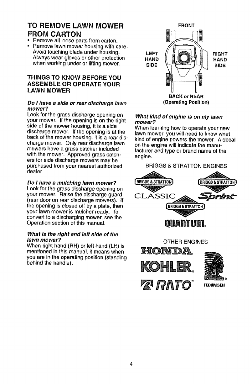
What is the right and left side of the
lawn mower?
When right hand (RH) or lefthand (LH) is
mentionedin this manual, it means when
you are in the operating position (standing
behind the handle),,
FRONT
LEFT
HAND
SIDE
BACK or REAR
(Operating Position)
What kind of engine is on my lawn
mower?
When learning how to operate your new
lawn mower, you willneed to know what
kind of engtne powers the mower, A decal
on the engine witl indicate the manu-
facturer and type or brand name of the
engine,,
BR1GGS& STRAT£ON ENGINES
RIGHT
HAND
SIDE
QU HTUm.
OTHER ENGINES
RATO °
Page 5

_CAUTION" Do not operate this lawn
mower without the discharge guard or an
entire approved grass catcher in place°
These guards are for your protection and
are required by the American National
Standards Institute and Consumer Prod-
ucts Safety Commission°
_GAUTION: Disconnect spark plug wire
from spark plug and place wire where it
cannot come in contact wilh plug
HOW TO SET UP YOUR MOWER
UNFOLD HANDLE
IMPORTANT: Unfold handle carefully so
as not to pinch or damage control cables.
2 POSITION / "ADJUSTABLE" HANDLES
o Raise handles until lower handle section
locks into place in operating position°
"QUICK RELEASE" HANDLES
,, Move height adjustment lever forward to
raise mower to highest position,.
- Tighten handle bolts (on both sides),
Operator MOWING
presence
control
UP
handle
Handle
lever
, Insert handle bolt through handle and
bracket and secure with knob_
o Repeat for opposite side of handle,
Knob
Handle
bracket
Bolt
3 POSITION "QUICK" HANDLES
• Raise lower handle section to operating
position and squeeze lhe bottom ends
of lower handle towards each other
until the pin in handle can be inserted
into one of the three height adjustment
holes.
SQUEEZE
J
Handle
adJ,
bracket
p_n
Handle
Height
adjuster
level
LEVER
FORWARD
TO RAISE
MOWER
3 POSITION "EZ" HANDLES
° Raise lower handle section to operating
position and align hole in handle with
one of three height positioning holes_
ALL HANDLES
" Raise upper handle section into place on
bolt
lower handle, remove protective padding
and tighten both handle knobs.
,, Remove handle padding holding opera-
tor presence control bar to upper handler
• Your lawn mower handle can be ad-
justed lor your mowing comfort. Refer to
"ADJUST HANDLE" in the Service and
Adjustments section of this manual
NOTE: For shipping purposes, the rear
wheels on your lawn mower may not be
adjusted to the same position as the front
wheels. Before operating mower adjust all
5 wheels to the same cutting height,
Page 6

INSTALL REAR WHEELS "FABRIC TOP" GRASS CATCHERS
("HIGH WHEEL" MOWERS ONLY)
Some high wheel models require washers
which will be provided in a parts bag, If
provided, install washers on the axle first
as shown,
+ Install one (1) rear wheel on the axle of
rear wheel adjuster_
, Install 3/8-16 locknut and tighten se+
curely.
,, Repeat procedure for other rear wheel,
Axle
TO ASSEMBLE AND ATTACH GRASS
CATCHER
• Put grass catcher frame into grass bag
with rigid part of bag on the bottom,,
° Slip vinyl bindings over frame+
NOTE: Ifvinyl bindings are too stiff, hold
them inwarm water for a few minutes° if
bag gets wet, tet it dry before using+
= Lift the rear door on the mower housing,,
, For HINGE BRACKET mounted catcher,
place the grass catcher frame onto the
formed tabs on the rear door hinge
bracket.
"_'---_ Reardoor
Hingebracket
tocknut assembly
ASSEMBLE GRASS CATCHER
(REAR DISCHARGE MOWERS ONLY)
IMPORTANT: Ifyour model lawn mower
Formed tabs
is mulcher ready, the mutcher plate or plug
must be removed before using mower as
a bagger+To converl mower to bagging or
discharging, see the Operation section in
this manual,
Look at the different grass catcher illustra-
tions that follow, Determine which type
° For HANDLE BRACKET mounted
catcher, place frame side hooks into
slots in handle brackets,
of grass catcher you have and follow the
appropriate instructions+,
\
Frame
handle
Handte bracket Rear
Grass
catcher
frame
Grass
catcher
handle
Frame
opening
\
Catcherframesidehook
Page 7

. For DOOR PIVOT PIN mounted cafcller,
place lhe grass catcher Irame tlooks
onto the door pivot pins
_tns Rear Grass
catcher
handle
Catcher frame hook ",
SPARK PLUG BOOT
On some models a spark plug boot is
packed loose in the parts bag.. If your
model has the boot, install on spark plug
wire and reconnect spark plug wire to
spark plug..
. For DOOR SLOT mounted catcher,
place the grass catcher frame hooks into
the slots of the rear door.
NOTE: The grass catcher is secured to the
lawn mower housing when the rear door is
lowered onto the grass catcher frame..
__ ._.__ Reardoor slots
Grass
Catcherframehook "_'_.. ""'-. "" -. t
ALL GRASS CATCHERS
,_CAUTION; Under normal usage, the
catcher material is subjec! to deterioration
and wear and should, therefore, be
checked frequently for replacement° Any
replacement catcher should be checked to
ensure compliance with original manufac*
turer's specilicalions_
_,CAUTION: Do not run lawn mower
without the discharge guard (rear door),
approved grass catcher, clipping deflector
or mulcher plate in place. Never attempt
to operate mower with the discharge guard
(rear door) removed or propped open.
\
Boot
Page 8

TO PREPARE BATTERY
(ELECTRIC START MODELS ONLY)
NOTE: Your battery must be charged
before you can start your lawn mower°
= Open battery box (if equipped)°
• Disconnect engine connector (male)
(if equipped) from battery connector
(female),
o Connect battery charger connector
(male) to harness connector (female),.
o Plug battery charger into 110 voll AC_
outlet,,
• Leave batterycharger connected for 24
hours before startingyour engine lor the
first time,
, Reconnect engine connector(male) (if
equipped) to battery connector (female)_
- After charging, connect engine connector
(male) (if equipped) to battery connector
(female),
Connect your battery charger to charge
battery after each use°
IMPORTANT: The engine will not recharge
your battery_
At lhe end of the mowing season the
battery should be charged for 48 hours to
tect the battery during winter storage_
AUTION: Always disconnect the
engine connector from the battery con-
nector to prevent accidental starting when
transportingor storing your lawn mower
after the season,
HANDLE-MOUNTED KEY SWITCH
Engine Harness
connector connector
\
connector(male)
22PLUS FRONT WHEEL DRIVE
Englne battery Battery
Charger
connector
(male)
Battery connector (female)
ale)
Charger
DECK-MOUNTED BATFERY
Battery Batlery
Charger
Harness
connector
connector
(m_
box
(female)
Engfne connector (male)
22PLUS REAR WHEEL DRIVE
Harness
connector
Battery char!
hale)
Battery
box
Page 9
The operation of any lawn mower can result in foreign objects thrown into
the eyes, which can result in severe eye damage, Always wear safety
glasses or eye shields while operating your lawn mower or performing any
adjustments or repairs. We recommend standard safety glasses or a wide
vision safety mask worn over spectacles.
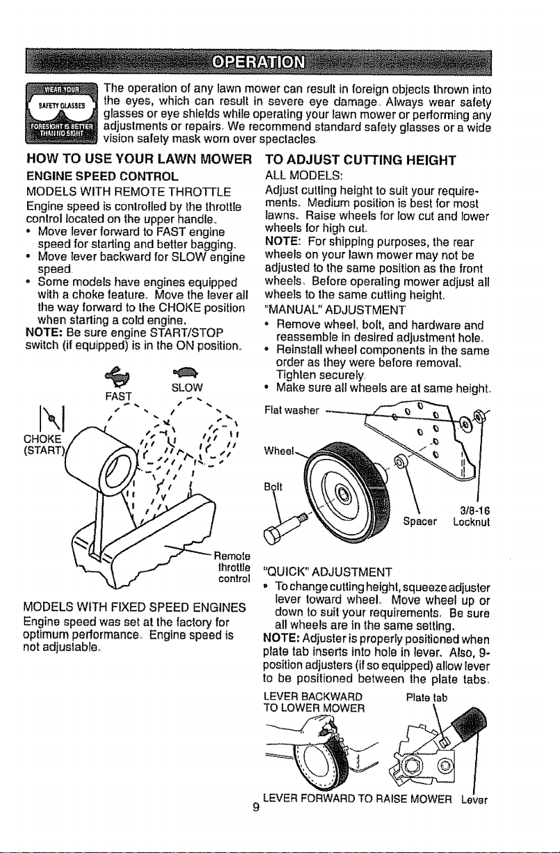
HOW TO USE YOUR LAWN MOWER
ENGINE SPEED CONTROL
MODELS WITH REMOTE THROTTLE
Engine speed is controlled by the throttle
control located on the upper handle,,
° Move lever forward to FAST engine
speed for starting and better bagging°
. Move lever backward for SLOW engine
speed.
o Some models have engines equipped
with a choke feature° Move the lever all
the way forward to the CHOKE position
when starling a cold engine,
NOTE: Be sure engine STARTtSTOP
switch(if equipped) isin theON positiom
FAST _ ..
SLOW
CHOKE _" _ t ;' IJ 1€1 .'
{START)// _' ,,/_'/"t'- : C ",_"
I /// \| . / I,,, ,'
\ Ill Ih. _/ / t "
TO ADJUST CUTTING HEIGHT
ALL MODELS:
Adjust cutting height to su_tyour require-
mentso Medium position is best for most
lawns° Raise wheels for low cut and lower
wheels for high cut..
NOTE: For shipping purposes, the rear
wheels on your lawn mower may not be
adjusted to the same position as the front
wheels, Before operaling mower adjust aH
wheels to the same cutting height..
"MANUAL" ADJUSTMENT
° Remove wheel, bolt, and hardware and
reassemble indesired adjustment holeo
° Reinstall wheel components in the same
order as they were before removal.
Tighten securely.
= Make sure ait wheels are af same height.
Fiat washer
Z
emote
_'_( J "throttle
_ff control
MODELS WITH FIXED SPEED ENGINES
Engine speed was set at the factory for
optimum performance,. Engine speed is
not adjustable.
Spacer Locknut
"QUICK" ADJUSTMENT
° To changecutting height, squeeze adjuster
lever toward wheel., Move wheel up or
down to suit your requirements. Be sure
all wheels are in the same setting.
NOTE: Adjuster isproperly positioned when
plate tab inserts intohole in lever, Also, 9-
position adjusters (if so equipped) allow lever
to be positioned between the plate tabs.
LEVERBACKWARD Plate tab
TO LOWERMOWER
LEVERFORWARDTO RAISEMOWER Lever
9
31B-16
Page 10
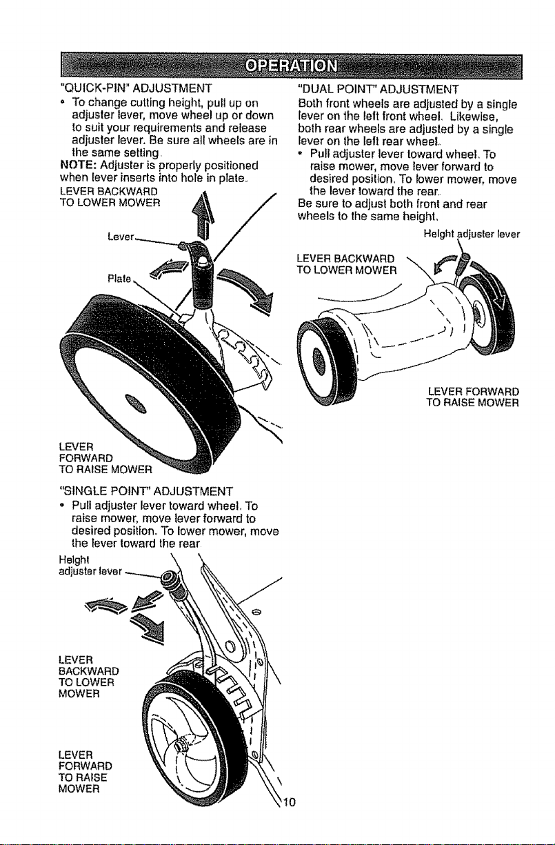
"QUICK+PIN"ADJUSTMENT
. To change cutting height, pull up on
adjuster lever, move wheel up or down
to suit your requirements and release
adjuster lever. Be sure all wheels are in
the same setting.
NOTE: Adjuster is properly positioned
when lever inserts into hote in plate,.
LEVERBACKWARD
TO LOWERMOWER
LEVER
FORWARD
TO RAISE MOWER
"SINGLE POINT" ADJUSTMENT
o Pull adjuster lever toward wheel. To
raise mower, move lever forward to
desired position.. To lowermower, move
the lever toward the rear
Height
adjl
"DUAL POINT" ADJUSTMENT
Both front wheels are adjusted by a single
lever on the lett front wheel.. Likewise,
both rear wheels are adjusted by a single
lever on the lelt rear wheel+
, Pull adjuster lever toward wheel. To
raise mower, move fever forward to
desired position.. To lower mower, move
the lever toward the rear+.
Be sure to adjust both front and rear
wheels to the same height,
ght fever
LEVER BACKWARD
TO LOWER MOWER
LEVER FORWARD
TO RAfSE MOWER
LEVER
BACKWARD
TO LOWER
MOWER
LEVER
FORWARD
TO RAfSE
MOWER
\
'1o
Page 11
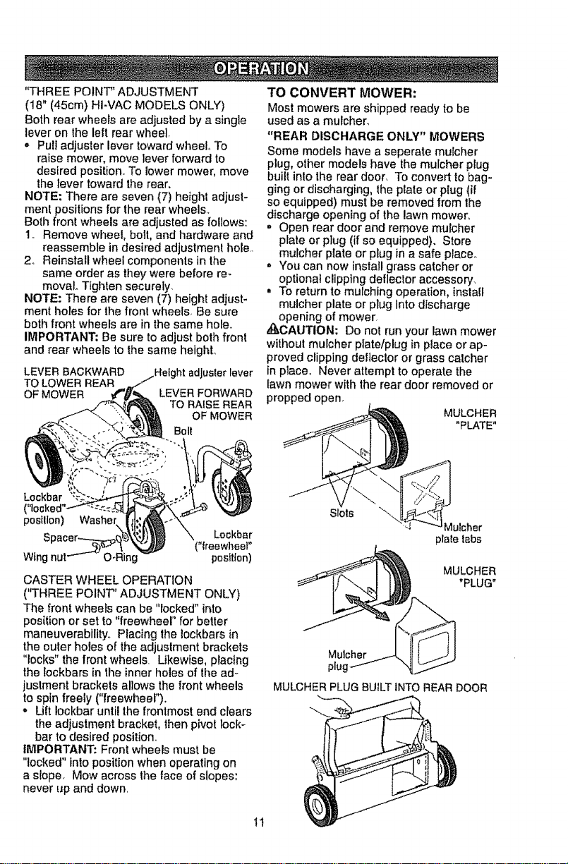
"THREE POINT" ADJUSTMENT
(18" (45cm) HI-VAC MODELS ONLY)
Both rear wheels are adjusted by a single
lever on lhe left rear wheel,
o Pull adjuster lever toward wheel° To
raise mower, move lever forward to
desired position. To lower mower, move
lhe lever toward the rear.
NOTE; There are seven (7) height adjust-
ment positions for the rear wheels..
Both front wheels are adjusted as follows:
!.. Remove wheel, bolt, and hardware and
reassemble in desired adjustmenl hole..
2o Reinstall wheel components in the
same order as they were before re-
moval. Tighten securely.
NOTE: There are seven (7) height adjust-
ment holes for the front wtleels, Be sure
both front wheels are in the same hole.
IMPORTANT: Be sure to adjust both front
and rear wheels to the same heighL
LEVER BACKWARD
TO LOWER REAR
OF MOWER
LEVER FORWARD
TO RAISE REAR
OF MOWER
Bolt
Lockbar
(
postllon)
Wing
CASTER WHEEL OPERATION
("THREE POINT" ADJUSTMENT ONLY)
The front wheels can be "locked" into
position or set to "freewheel" for better
maneuverability.. Placing the lockbars in
the outer holes of the adjustment brackets
"locks" the front wheels. Likewise, placing
the !ockbars in the inner holes of the ad-
justment brackets al]ows the front wheels
to spin freely ("freewheeF).
• Lift Iockbar until the frontmost end clears
the adjustment bracket, then pivot lock-
bar to desired position,.
IMPORTANT: Front wheels must be
"locked" into position when operating on
a sloper Mow across the face of slopes:
never up and down.
Washer
Lockbar
("treowheel"
position)
TO CONVERT MOWER:
Most mowers are shipped ready to be
used as a mulchero
"REAR DISCHARGE ONLY" MOWERS
Some models have a seperate mulcher
plug, other models have the mulcher plug
built into the rear door, To convert to bag-
ging or discharging, lhe plate or plug (if
so equipped) must be removed from the
discharge opening of the lawn mower.
. Open rear door and remove mulcher
plate or plug (if so equipped). Store
mulcher plate or plug in a safe place.
. You can now install grass catcher or
optionat clipping defleclor accessory.
° To return to mulching operation, install
mulcher plate or plug into discharge
opening of mower.
,,_CAUTION: Do not run your lawn mower
without mutcher plate/plug in place or ap-
proved clipping defteclor or grass catcher
in place.. Never attempt to operate the
lawn mower with the rear door removed or
propped open,
MULCHER
"PLATE"
Slots
Mutcher
plale tabs
__i_ MULCHER
__ "PLUG"
Mutcher j...J... It{ _.JJ
plugf --/ -,.j_C..I--
MULCHER PLUG BUILT iNTO REAR DOOR
I1
Page 12

"SIDEDISCHARGE ONLY" MOWERS
MULCHER PLATE
To convert to bagging or discharging,
mulcher plate must be removed from un-
derside of lawn mower_
o Remove thefour (4) screws and locknuts
securing the mulcher plate tothe mower,,
* Store mulcher plate and hardware in a
sale place.
o Mower can now be used for side
discharging or optional grass catcher
accessory can be attached
o To return to mulching operation, simply
reinstall mulcher plate and tighten hard-
ware securely.
locknut
Mulcher
plate
MULCHER PLUG TYPE "B"
To convert to bagging or discharging:
,, Lift discharge guard and remove
mulcher plug.
• Mower can now be used for side dis-
charging or optional grass catcher can
be attached.
° To return to mulching operation, simply
reinstallmulcher plug as shown, making
sure tab is seated properly,.
_CAUT1ON: Do not runyour lawn mower
without discharge guard, approved grass
catcher or mulcher plug in place.
Lift
dtschar
guard
MULCHER PLUG TYPE "A"
To convert to mulching operation, mulcher
plug must be installed into discharge open-
ing o! mower,
• Open discharge guard°
. Insert tab of mulch plug Into housing
opening
• Alignhooksofmulchplugoverhinge
rodofdischargeguard Push mulch plug
down until mulch plug is seated in hous-
_}ing opening.
CAUTION: Do not run your lawn mower
without discharge guard, approved grass
catcher or mulcher plug in place.
Hinge
Discharge
Mulcher plug 12
Install Tab
mulcher
MOWER IS
NOW READY
FOR MULCHING
OPERATION
Page 13

"MULTI-CUT" MOWERS
Your lawn mower was shipped ready to be
used as a mutcher To convert to bagging
or discharging:
REAR BAGGING
o Open rear door and remove mulcher
plate or plug (if equipped) Store
mulcher plate or plug in a safe place
• You can now tnslall grass catcher.
= To convert to mulching or discharging
operation, install mulcher plate or plug (if
equipped) into rear discharge opening of
mower, making sure all labs are seated
properly_ Close rear door.
SIDE DISCHARGING
• Mulcher plate or plug (if equipped) must
be installed into rear discharge opening
of mower. Rear door must be clesed_
o Open mulcher door and installdischarge
deflector under door as shown.
o Mower is now ready for discharging
operation.
o To convert to mulching or bagging
operation, discharge deflector must be
removed and mulcher door must be
closed and locked..
bracket Grass
g
catcher
handle
catcher
frame :-,:,..
hook equipped)
"REAR DOOR PROP" (IF EQUIPPED)
(22PLUS MODELS ONLY)
NOTE: Rear door will remain open until
operator presence control bar is held down
to the handler
,_,CAUTION, Do NOT force rear door to
close° Serious damage to your mower
Open muicher door
Discharge
deliector
\
t3
Page 14

SIMPLESTEPSTOREMEMBER
WHENCONVERTINGYOUR
"MULTI-CUT"LAWNMOWER:
FORMULCHING-
oRearmulcherplateorplug(ifequipped)
installedandreardoorclosed.,
. Mulcherdoorclosed,.
FORREARBAGGING-
° Rear mutcher plate or plug (if equipped)
remove&
o Grass catcher installed,
° Mulcher door closed°
FOR SIDE DISCHARGING
° Rear mulcher plate or plug (if eqLlippsd)
installed and rear door closed.
- Discharge deflector installed.
_CAUTION: Do not run your lawn mower
without rear mulcher plate or plug ihplace
or approved grass catcher in place° Ne,_er...
attempt to operate the lawn mower with
the rear door removed oT:'prop.pedopen.
....-,..,; Mower is now ready for rear bagging
18" (45cm) HI-VAC MODELS:
Your lawn mower was shipped ready to
be used as a mulchero To convert to rear
bagging or side discharging:
REAR BAGGING
1o Remove knob securing mulcher door
to lawn mower housing.
2. Open mulcher door and position dis-
charge chute over both threaded studs,
3. Secure discharge chute to lawn mower
housing with both knobs.,
4. Place the grass catcher on the rear
door as shown°
NOTE: Be sure the grass catcher is se-
curely locked in place_
bperation,,
Grass catcher
TO EMPTY GRASS CATCHER (REAR .......
DISCHARGE AND MULTI-CUT MODELS)If='.'/
• Simply open rear door and lift grass " ,':_._y:':'_
catcher up and away from mower,
NOTE: Do not drag the bag when
emptying, it will cause unnecessary wear. Dts-
_,CAUTION: Under normal usage, the charge
catcher material issubject to deterioration
and wear and should, therefore, be
checked frequentlyforreplacemenL Any
replacement catcher should be checked
to ensure compliance with original
manufacturer's specifications.
&CAUTION: Do not run lawn mower
without the rear door, approved grass
catcher or clipping deflector in place.,
Never attempt to operate mower with lhe
rear door removed or propped open_
j' // Gross
/ / catcher
//_ \ t frame
.......... ; ;-";,._jr a
(if equipped) _,_,
Threaded stud
SIDE DISCHARGING
I, Discharge chute must be removed.
2. Open mulcher door and installside dis-
charge deflector beneath it as shown.
andle
14 Side discharge deflector
Rear door
Knobs
Mutcher
door
door
Page 15

3. Secure rear of side discharge deflector
to lawn mower housing with knob_
= Mower isnow ready for side discharging
operation,
SIMPLE STEPS TO REMEMBER WHEN
CONVERTING YOUR 18" HI-VAC:
FOR MULCHING -
1- Grass catcher, discharge chute and
side discharge deflector removed
2. Mulcher door secured to mower hous-
ing with knob
FOR REAR BAGGING -
1. Side discharge deflector removed.
2. Grass catcher and discharge chute
installedwith discharge chute secured
to lawn mower housing with knob,
FOR SIDE DISCHARGING -
1_ Grass catcher and discharge chute
removed
2. Side discharge deflector installed and
secured to mower housing with knob_
,_CAUTION: Do not run your lawn mower
wllhout mulcher door closed; side dis-
charge deflector installed, or discharge
chute and approved grass catcher in
place,, Never attempt to operate the lawn
mower with mulcher door removed or
propped open.
TO EMPTY GRASS CATCHER
1. Remove grass catcher with clippings
from lawn mower using both front and
center of handle as shown°
2 Empty clippings from grass catcher,
3, Reinstall grass catcher on rear door,
NOTE: Do not drag the bag when empty-
ing; it will cause unnecessary wear,
Handle
21" (53cm) HI-VAC MODELS:
Your lawn mower was shipped ready to
be used as a mulcher., To convert to rear
bagging or side discharging:
REAR BAGGING
1, Remove knob securing mulcher door to
lawn mower housing°
handle
,Crossbar
Grass
Round
door
_%_Knob
chute
Threaded
stud
Mulchor door
2_
Open mulcher door and insert tabs
of discharge chute into hinge bracket
opening and position rear of chute over
threaded stud,,
15
Hinge bracket Muicher door
Page 16

3,,Securerearofdischargechute;tolawn........
mowerhousingwithknob,
4, Placerearhandleofgrasscatcheron
thecrossbarofthelawn mower's tower
handle as shown.
5,, Lift the round door of the discharge
chute and place the grass catcher _nto
place on the discharge chute,
NOTE: Be sure the grass catcher is se-
curely locked in place and the round door
of the discharge chute rests on the grass
catcher as shown°
• Mower is now ready for rear bagging
operation,.
° To convert to mulchtng operation,
remove grass catcher and discharge
chute_ Secure mulcher door to mower
housing with knob,,
° To convert to side discharging operation,
remove grass catcher and discharge
chute, Install side discharge deflector
and secure it to lawn mower housing
with knob°
SIDE DISCHARGING
1. Grass catcher and discharge chute
must be removed,,
2. Open mulcher door and install front of
side discharge deflector beneath it as
shown,
3. Secure rear of side discharge deflector
to lawn mower housing with knob°
,, Mower is now ready for side discharging
operation°
° To convert to mulching operation, side
discharge deflector must be removed
and mulcher door secured to mower
housing with knob.
,, To convert to rear bagging opera-
tion, side discharge deflector must be
removed; discharge chute and grass
catcher installed and discharge chute
secured to mower housing with knob.,
Mulcherdoor
\
stud
Side
discharge
deflector
WHEN CONVERTING YOUR 21" HI-VAC:
FOR MULCHING -
1, Grass catcher, discharge chule and
2, Mulcher door secured to mower hous-
FOR REAR BAGGING -
1. Side discharge deflector removed
2., Grass catcher and discharge chule
3o Round door of discharge chute resting
FOR SIDE DISCHARGING -
1, Grass catcher and discharge chute
2- Side discharge deflector _nstal]edand
,_CAUTION: Do not run your lawn mower
without mulcher door closed; side dis-
charge deflector installed, or discharge
chute and approved grass catcher in
place° Never attempt to operate the lawn
mower with mulcher door or round door
removed or propped open.
TO EMPTY GRASS CATCHER
1. Open round door of discharge chute to
' _\. Front
OPEN
Round Starter
door rope
2, Remove grass catcher with clippings
3, Empty clippings from grass catcher
4. Snap door shut over frame before
NOTE: Do not drag the bag when empty-
16ing; il will cause unnecessary wear.
SIMPLE STEPS TO REMEMBER
stde discharge deflector removed,
ing with knob.
installed with discharge chute secured
to lawn mower housing with knob
on top of grass catcher.
removed_
secured to mower housing with knob,
move starter rope out and away from
grass catcher,,
from lawn mower using both front and
rear handles,
using rear handle° The weight of the
grass will open the door°
installing grass catcher on mower.
Page 17

OPERATORPRESENCE CONTROL
BAR (ALL MODELS)
Your lawn mower is equipped with an op-
erator presence control bar which requires
the operator to be positioned behind the
lawnmower handle in order to start and
erate the lawn mower_
AUTION: Federal regulations require
an engine control to be installed on this
lawn mower in order to minimize the risk
of blade contact injury, Do not under
any circumstances attempt to defeat the
function of the operator control. The blade
turnswhen the engine is running,
DRIVE CONTROL
"STANDARD" DRIVE CONTROL
° Self-propelling is controlled by holding
the operatorpresence control bar down
tothe handle and pushing the drive
controllever forward until itclicks;then
re_easing the lever,
o Forward motion will stop when the op-
erator presence control bar is released,,
To stop forward motion without stopping
engine, release the operator presence
control bar slightly until the drive control
disengages_ Hold operator presence
control bar down against handle to con-
tinue mowing without self-propelling,
o To keep drive control engaged when
turning corners, push down on handle
and lift front wheels off ground while
turning lawn mower,,
TO ENGAGE DRIVE CONTROL
17
Operator
presence
contro_bar
DRIVE CONTROL DISENGAGED
Page 18

"DUALBAIL" DRIVE CONTROL
. Tostart forward motion, lift drive control
bar up to handle°
° Tostop forward motion, release drive
control bar_
Operator
presence
control bar
DRIVE CONTROL ENGAGED
DRIVE CONTROL DISENGAGED
"AUTOWALK" DRIVE CONTROL
o Self-propelling is controlled by holding
the operator presence control bar down
to the handle and pulling the ddve con-
trollever(s) rearward to the handle. The
farther toward the handle the lever(s)
are pulled, the faster the unit will travel.
. Forward motion will stop when either
the operator presence control bar or a
drive control lever are released° To stop
forward motion without stopping engine,
release the drive control lever(s) only.
Hold operator presence control bar
down against handle to continue mowing
withoutself-propelling,
NOTE: If after releasing thedrive control the
mowerwili not rollbackwards, push the mower
forward slightly to disengage drive wheels,,
control presence
lever(s) control ba_
TO ENGAGE DRIVE CONTROL
turnbuckle
DRIVE CONTROL DISENGAGED
FRONT WHEEL DRIVE MODELS ONLY:
- To keep drive control engaged when
turning corners, push down on the
handle to lift the front wheels off the
ground while turning lawn mower,
18
Page 19

Overtime,thedrivecontrolsystemmay
become"loose",resultingindecreased
speed°Thereisatumbucldeonthe
undersideofthedrivecontrolhousingto
increasetensiononthedrivecable.Pro-
ceedasfollows:
- Turnunitoffanddisconnectspad(plug
wirefromsparkplug.
,, Turn nut on underside of drive control to
increase drive speed.
,' Operate mower to test drive speed°
Readjust as required
, Ifcondition fails to improve after the
above steps (forward speed remains
the same), your drive bait is worn and
should be replaced.
turnbuckEe
/
"VARI-SPEED"DRIVECONTROL
o Serf-propelling is controlled by hold-
ing the operator presence control bar
down to the handle and pulling the drive
control bar up to the handle. The closer
to the handle the bar is pulled, the faster
the unit wilt travel..
o Forward motion will stop when either the
operator presence control bar or drive
control bar are released, To stop forward
motion without stopping engine, release
the drive control bar only Hold operator
presence control bar down against
handle to continue mowing without self-
propelling.
NOTE: If alter releasing the drive control the
mowerwi!l not rollbackwards, push the mower
forward slightly to disengage drive wheels.
FRONT WHEEL DRIVE MODELS ONLY:
- To keep drive control engaged when
turning corners, push down on the
handle to lift the front wheels off the
ground while turning lawn mower,.
oratorpresencecontrolbar
controlbar
DRIVE
CONTROL
DISENGAGED
TO ADJUST,
MOVE DOWN
TO NEXT HOLE
Over time, the drive control system may
become "loose", resulting in decreased
speed.. There are holes in the drive control
housing to increase tension on the drive
cable. Proceed asfollows:
, Turn unit off and disconnect spark plug
wire from spark plug.
° Loosen nut, move drive control hous-
ing down handle to the next hole and
retigh|en nut.
,, Operate mower to test drive speed.
° Ifcondition falls to improve after the
above steps (forward speed remafns
the same), your drive belt is worn and
should be replaced.
19
Page 20

BEFORE STARTING ENGINEI:' :::::::::::::::::::::::Ifyour mower has a primer, to start a
Read the engine manual packed with your
mower,,
FILL ENGINE WITH OIL
Your lawn mower is shipped without oil in
the engine.
o Be sure mower is level and area around
oil fill is clean,
o Remove engine oil rifler plug (oil fill cap/
dipstick on models so equipped)°
- Slowly add oil For type and grade of
oil to use, see "ENGINE" in the Mainte-
nance section of this manual,,
• Fill to the top of slot in filler hole (to
"FULL" line on dipstick on models so
equipped). Do not overfill
• Replace plug (oil fill cap/dipstick on
models so equipped) and tighten.
o Ctteck oil level before each use,, Add oil
as needed.
o To change oil, see Maintenance section
of this manual,
FILL GASOLINE TANK
• Fill gasoline tank with fresh, clean,
unleaded gasoline, DO NOT USE PRE-
MIUM GASOLINE, BE CAREFUL NOT
TO OVERFILL TANK,
WARNING: Alcohol blended tuels (called
gasohol or using ethanol or methanol) can
attract moisture which leads to separation
and formation of acids during storage. Acidic
gas can damage the fuel system ofan engine
whiEein storage,, To avold engine problems,
the fuel system should be emptied before
storage of 30 days or longer° Drain the fuel
tank, start the engine and let it run until fuel
lines and carburetor are empty. Use fresh
fuel next season, See Storage Instructions
for additional Information. Never use engine
or carburetor cleaner products inrue!tankor
permanent damage may occur,
TO START ENGINE
_CAUTION: The mower blade rotates
whenever the engine is running_
NOTE: Due to protective coatings on the
engine, a small amount of smoke may be
presentduring the initial use of the product
and should be considered normal,
,, Place engine START/STOP switch (if
equipped) in the ON position.,
• Move engine speed control to FAST
position (or to CHOKE/START position
on models equipped with choke feature),
cold engine, push primer as many times
as instructed in the engine manual
packed with your mower_ Use a firm
push_This step is not usually necessary
when starting an engine which has
already run for a few minutes
• Hold operator presence control bar
down against handle.
MODELS WITH RECOIL STARTER
o Pull starter handle quickly, Do not allow
starter rope to snap back.
MODELS WITH ELECTRIC STARTER
• Push the engine start button (or turnthe
key on models so equipped).
IMPORTANT: Do not crank engine more
than five continous seconds each time you
tnj tostart,, Wait 5 to !0 seconds between
each attempt°
ALL MODELS
° For engines equipped with choke, slowly
move engine speed control lever to
FAST after engine starts.,
TO STOP ENGINE
° To stop engine, release operator pres-
ence control bar and/or place engine
START/STOP switch (it equipped) in the
OFF position..
NOTE: For engines with a primer, it may
be necessary to repeat priming steps
incooler weather, In warmer weather,
overpriming may cause flooding and
engine will not start,, If you do flood
engine, wait a few minutes before
attempting tostart and DO NOT repeat
priming steps,,
2O
Page 21

MOWING TIPS
CAUTION: Do not use de-thatcher
blade attachments on your mower, Such
attachments are hazardous, will damage
your mower and could void your warranty_
° For most cutting conditions and better
bagging performance, the engine speed
should be set in the FAST position,,
o Under certain conditions, such as when
mowing very tal_grass, raise the mower
height on the first cut to reduce pushing
effort, to avoid overheating the engine,
and to avo+dleaving clumps of grass
c}ippings,. Make the second cut to the
desired height,
• For extremely heavy cutting, reduce the
width of cuL
. For side discharge lawn mowers, cut in
a counterclockwise direction, starting at
the outside o! the area to be cut, in order
to spread grass clippings more evenly
and toput less load on the engine. To
keep clippings off of walkways+ flower
beds, elc. make the first cuts in a clock-
wise direction,
, When using a rear discharge lawn
mower in moist, heavy grass, clumps
of cut grass may not enter the grass
catcher. Reduce ground speed (pushing
speed) and/or run the lawn mower over
the area a second time,,
o tf a trailof grass clipping is left on the
right side of a rear discharge lawnmow-
er,mow in a clockwise direction with a
small overlap to collect the clippings on
the next pass,
FOR MULCHING MOWERS ONLY
+MULCHING MOWING TIPS
IMPORTANT; For best performance, keep
mower housing free of built-up grass and
trash, See '*CLEANING" in the Mainte-
nance section of this manual.
, The special mulching blade wilt recut the
grass clippings many times and reduce
them in size so that as Ihey fall onto the
lawn they will disperse into the grass
and not be noticed., Also, the mulched
grass will biodegrade quickly to provide
nutrients for the lawn. Always mulch with
your highest engine (blade) speed as
thiswilt provide the best recutting action
of the blades°
. Avoid cutting your lawn when it is wet
Wet grass tends to form clumps and
interferes with the mulching action. The
best time to mow your lawn is the early
afternoon, At this timethe grass has
dried, yet the newly cut area will not be
exposed to direct sunlight,
• For best results, adjust the lawn mower
cutting height so that the lawn mower
cuts off only the top one-third of the
grass blades, tf the lawn is overgrown it
will be necessary to raise the height of
cut to reduce pushing effort and to keep
from overloading the engine and leaving
clumps of mulched grass. For extremely
heavy grass, reduce your width of cut
by overlapping previously cut path and
mow slowly.
MAX tt3
Pores in cloth grass catchers can
become filled with dirt and dust with use
and the catcher will collect less grass,
To prevent this, regularly hose catcher
off with water and let dry'before use+
,tl
Certain types of grass and grass
conditions may require that an area be
mulched a second time to completely
hide the clippings. When doing a second
cut, mow across (perpendicular) to the
first cut path+
Change your cutting pattern from week
to week, Mow north to south one week
then change to east towest the next
week, This will help prevent matting and
graining of the lawn..
21
Page 22

MAINTENANCE ieEFORE
SCNEDILILIE USE
JJ
Check {orLoose Fasteners V'
L Clean /inspect G'mssCatcher"
_i_ec_T.es ......................V'
W Check DriveWheels "" '............
EACH
t/
AFTER ! EVERY EVERY EVERY
EACH !0 25 HOURS 100 BEFORE
USE HOURS OR SEASON HOURS STORAGE
V' .................. v'
, J,, :
CieanLawnMower"_';; J
l,,n'_'i'ean'underDrivecowr'" .... [ ..............I' 'F' ....
0 Check Drb'_ Be'li'7'Pulreye"'* " ........................ ti/ ..............
w Check/Sharpa./ .epla_,;'Bi_d;' V'_ '
Lubrication ............... _ .............
IR Clean and Recharge Batlery '" 1_ l_
Check Engine OIl level V_ .........
E Eo, n,Oii .......... ' ..... ................
N
Clean ,_ir Fiiie'i;................ J .......... _/2' '
?
_=p,ciMu,,er...................... I _iii'7'iii"ii'ii'
NI--'RePleCe_§paik Plug ........... l ...... V
E RePlace Air Filler.Paper Cartridge I_
Empty fuef system or add Slabllizer 1_ .....
* (If so equipped} 1 - Change more often if operating under a heavy load or In t_,Ighoutdoor temperatures
** Eleclrlc-Slart mowers 2 - Service more ellen IIoperating indilly or dusty cof_ditions
*** Power-Propelled mowers 3 - Replace bLRdes more alton whsn mowing tn sandy soil
**** Use a scraper 4 - Charge 4B hours at end el season
to cteen trader deck 5 - And after each 5 hours el use,
GENERAL RECOMMENDATIONS
The warranty on this lawn mower does not
cover items that have been subjected to op-
erator abuse or negligence., To receive fu_l
value from the warranty, operator must main-
tain mower as instructed in this manual..
Some adjustments will need to be made
periodically to properly maintain your uniL
All adjustments in the Service and Adjust-
ments section of this manual should be
checked at least once each season°
• Once a year, replace the spark plug,
clean or replace air tilter element, and
check blade for wear. A new spark plug
and clean/new air filter elemenl assures
proper airfuel mixture and helps your
engine run better and last longer.
• Fol!ow the Maintenance Schedule in this
manual.
BEFORE EACH USE
_') Handle bracket mounting ptns
• Check engine olilevel..
• Check for loose fasteners.
_) Spray lubricant
LUBRICATION
(_) See "ENGINE" tn Maintenance section,
Keep unil well lubricated
(See "LUBRICATION CHART"),.
attract dust and dirt thai wilt shorten the life
of the self-lubricating bearings., Ifyou feel
IMPORTANT: Do not oil or grease plastic
wheel bearings. Viscous lubricants will
they must be lubricated, use only a dry,
22Powdered graphite type lubricant sparingly°
'r:
LUBRICATION CHART
adjusler (on
each wheel)
Engine oil
Side dis-
charge mower
guard hinge rod
Rear dis-
charge mower
rear door
hinge rod
Wheel
Page 23

LAWN MOWER
Always observe safety' rules when per-
forming any maintenance
TIRES
o Keep tires free of gasoline, oil, or insect
control chemicals which can harm rub-
ber_
o Avoid stumps, stones, deep ruts, sharp
objects and other hazards that may
cause tire damage
BLADE CARE
For best results, blade must be kept sharp_
eplace a bent or damaged blade.
CAUTION: Use only a replacement
blade approved by the manufacturer of
your mower. Using a blade not approved
by the manufacturer of your mower is
hazardous, could damage your mower and
void your warranty.
TO REMOVE BLADE
1. Disconnect spark plug wire from spark
plug and place wire where itcannot
come incontact with plug
2. Turn lawn mower on its side. Make
sure air filter and carburetor are up.
3 Use a wood bFockbetween blade and
mower housing to prevent blade from
turningwhen removing blade bOlto
NOTE: Protect your hands with gloves
and/or wrap blade with heavy cloth,
4. Remove blade bolt by turningcounter-
c/ockwise_
5. Remove blade and attaching hard-
ware (bolt, lock washer and hardened
washer).
6. Remove debris shield (if equipped)
NOTE: Remove the blade adapter and
check the key inside hub of blade adapter.
The key must be in good condition to work
properly,. Replace adapter if damaged.
Belt
Ing edge
Debris shield Hardened
(if equfpped) washer
Blade Blade bolt
TO REPLACE BLADE
1. Position the blade adapter on the en-
gine crankshaft. Be sure key in adapter
and crankshaft keyway are aligned;
and that the drive belt is inside the tabs
of the belt retainer (if equipped).
2. Position blade on the blade adapter
aligning the two (2) holes in the blade
with the raised lugs on the adapter,
3,. Be sure the trailing edge of blade (op-
positesharp edge) is up toward the
engine,,
4, Inslalt the blade bolt with the lock
washer and hardened washer into
blade adapter and crankshaft,
5, Use block of wood between blade and
lawn mower housing and tightenthe
blade bolt, turning clockwise..
• The recommended tightening torque is
3540 frolbs..
IMPORTANT: Blade bolt is heat treated,.
If bolt needs replacing, replace only with
approved bolt shown in the Repair Parts
section of this manual.
TO SHARPEN BLADE
NOTE: We do not recommend sharpening
blade - but if you do, be sure the blade
is balanced. An unbalanced brade will
cause eventual damage to fawn mower or
engine°
• The blade can be sharpened with a file
or on a grinding wheel. Do not attempt
to sharpen while on the mower..
23
Page 24

BLADESWITH ROUND HOLE:
" To check blade balance, drive a nail into
a beam or wall. Leave about one inch of
tl_estraight nail exposed.. Place center
hole of blade over the head of the nail..
II blade is balanced, it should remain in
a horizontal position, If either end of the
blade moves downward, sharpen the
heavy end until the blade is balanced..
BLADES WITH "STAR" HOLE:
. To check blade balance, you will need
a 5/8" diameter steel boll, pin, or a cone
balancer. (When using a cone balancer,
follow the instructions supplied with
balancer..)
NOTE: Do not use a nail for balancing
blade The lobes ol the center hole may
appear to be centered, but are noL
o Slide blade on to an unthreaded portion
of the steel bolt or pin and hold the bolt
or pin parallel wilh the ground. If blade
is balanced, it should remain in a hori-
zontal position. If either end of the blade
moves downward, sharpen the heavy
end until the blade Is balanced
18" (45cm) HI-VAC MODELS ONLY:
I. Remove hubcaps (if equipped) and
locknuts=
2. Remove wheels from wheel adjuster
axles,
3o Remove any trash or grass cuttings
from inside the dust cover, pinion gear
and drive wheel gear teeth..
4. If you remove the pinion gears, wipe
clean with dry cloth Reassemble
dry. Do not lubricate. Do not use oil or
grease.
IMPORTANT: The pinion gears (on both
sides of the mower) are the same, how-
ever, they must be installed correctly_ If
installed incorrectly, the drive system will
not work_
5o There are arrows embossed on both
sides of the pinion gear_ Wilh the ar-
row at the top of the pinion, the arrow
must point towards the front of the
mower., If the arrow points to the rear
of the mower, turn the pinion around,
then assemble it to the mower.
6. Place wheels back on adjuster axles,.
7. Replace locknuts and hubcaps.
FRONT
OF
MOWER
CORRECT INCORRECT
DRIVE WHEELS
Check drive wheels each time before you
mow to be sure they move freely.
The wheels not turning freely means trash,
grass cuttings, etc. are in the drive wheel
area and must be cleaned to free drive
wheels.
If necessary to clean the drive wheels,
check both drive wheels
. Ifafter cleaning, the drive wheels do not
turn freely, contact your nearest autho-
rized service center,.
Plnton
gear
Washer Dust
Locknut
• If after cleaning, the drive wheels do not
turn freely, contact your nearest autho-
rized service center..
24
Cover
Page 25

GEARCASE
o To keep your drive system working
properly, the gear case and area around
the drive should be kept clean and free
of trash build-up. Clean under the drive
cover twice a season.
o The gear case is filled with lubricant to
the proper level at the factory, The only
time the lubricant needs attention is if
service has been performed on the gear
case,
ENGINE
Read the maintenance section of your
engine manual
LUBRICATION
Change the oil after the first twohours of
operationand every 25 hours thereafter or
at least once a year if the lawn mower is
not used for 25 hours in one year. Refer to
engine manual,,
TO CHANGE ENGINE OIL
(SEE ENGINE MANUAL)
, Be sure lawn mower ison level surface.
,, Oil will drain more freely when warm°
,, Catch oil in a suitable container.
. For engines without dipstick, remove
bottom oil drain plug,
° For engines with oil fill cap/dipstick,
remove bottom drain plug or remove en-
gine oil cap and turnmower on its side.
. After oil has drained completely, replace
oil drain plug and tighten securely°
. Refill engine with oil. Pour slowly. Do
not overfill.
= Fill to top of slot inside of filler hole or
to "FULL" line on dipstick on models so
equipped. Keep oil at proper level
AIR FILTER
Your engine will not runproperlyand may
be damaged by using a dirty air filter.
Clean the element after every 25 hours
of operation or every season_ Replace
the air filter every 100 hours of operation
or every season, whichever occurs first.
Service air cleaner more often under dusty
conditions° See the maintenance section
of your engine manual°
IN-LINE FUEL FILTER
(KOHLER ENGINES ONLY)
The fuel filter should be replaced once
each season, If fuel filler becomes
clogged, obstructing fuel flow to carburetor,
replacement is required.
1.. With engine cool, remove filter and plug
fuel line sections.
2. Place new fuel filter in position in tuel
line with arrow pointing towards carbu-
retor,
3, Be sure thereare no fuel line leaks and
clamps are properly positioned.
4 Immediately wipe up any spilled gaso-
line.
MUFFLER
inspect and replace corroded muffler as it
could create a fire hazard and/or damage
SPARK PLUG
Replace spark plug at the beginning of
each mowing season or after every 100
hours of operation, whichever occurs first.
Set spark plug gap according to engine
manual specifications°
CLEANING
IMPORTANT: Forbest performance, keep
mower housingfree of grass build-up and
trash.Clean the underside of your mower
after each use°
° Clean the underside of your lawn mower
by scraping to remove buildup of grass
and trash.
,, Clean engine often to keep trashfrom
accumulating,. A clogged engine runs
hotter and shortens engine life.
° Keep finished surfaces and wheels free
of all gasoline, oil, etc
We do not recommend using a garden
hose to clean your lawn mower unless the
electrical syslem, muffler, air filter, and
carburetor are covered to keep water out
Water in engine can shorten engine life.
CLEAN UNDER DRIVE COVER
Clean under the drive cover at least twice
a season,. Scrape underside of cover with
a putty knife or similar tool to remove any
buildup of trash or grass°
25
Page 26

WATER WASHOUT FEATURE
(IF EQUIPPED)
Your lawn mower may be equipped with a
fitting that allows quick and easy cleaning
of the underside of the housing° To use
this feature, proceed as follows:
1• Move lawn mower to an area of cut
grass or another hard surface
NOTE: Water, grass and other debris will
drain from beneath the mower housing
during the washout process,
2,, Remove grass catcher and discharge
chute assembly from lawn mower°
3, Close mulcher door (if equipped).
4, Connect a garden hose to the fitting
where shown,
IMPORTANT: Be sure the garden hose is
nol routed under the lawn mower housing
or entangled in the wheels,
5, Turn on water supply and check for
leaks at the fitting,
If no leaks are present, start engine (as
described in the Operation section of this
manual) and let engine run until the under-
side of the lawn mower is clean.
_, WARNING: Do not engage the drive
system during the washout process,
6, Shut off the engine.
7. Shut off water supply and remove hose
from fitting,
CAUTION: Do not remove hose from
tilting while engine isrunning,, Water in
engine can result inshortened engine life
& Start engine (as described in the Op-
eration section of this manual) and let
engine run for a full minute to remove
excess water from mower.,
Fitting
GRASS CATCHER (IF EQUIPPED)
Grass catcher may be hosed withwater
but must be dry when used°
_,CAUTION: Under normal usage, the
catcher material is subject to deterioralion
and wear and should therefore be checked
to ensure compliance with original
manufacturer specifications
26
Page 27

,_CAUTION:Beforeperforminganyser-
viceoradjustments:
oReleaseoperatorpresencecontrolbar
. Makesurethebladeandallmoving
parishavecompletelystopped.
,'Disconnectsparkplugwirefromspark
p)ugandplacewirewhereitcannot
comeincontactwithplug,
LAWN MOWER
TO ADJUST CUTTING HEIGHT
See "TO ADJUST CUTTING HEIGHT" in
the Operation section of this manual,
REAR DEFLECTOR
The rear deflector, attached between the
rear wheels of your mower, is provided to
minimize the possibility that obiects will
be thrown out of the rear of the mower
into the operator's mowing position Ifthe
deflector becomes damaged, it should be
replaced,
DISCHARGE GUARD (IF EQUIPPED)
The discharge guard, attached to the side
discharge opening of your lawn mower, is
provided to prevent the possibility of injury'
resulting from objects being thrown out of
the discharge opening into the operator
mowing position,. If the discharge guard
becomes damaged, itshould be replaced,
TO ADJUST HANDLE
"2 POSITION" HANDLES
The handle can be mounted in a high or
low position, The mounting holes in the
bottom of lower handle are off center for
raising or towering the handle,
) Remove upper handle and a)l parts at-
tached to lower handle,
• Remove hairpin cotters from lower
handle bracket mounting pin.
° Squeeze lower handle in to remove it
from mounting pins_
- Turn lower handle over to raise or lower
handle_
o Squeeze lower handle in and posilion
holes onto mounting pins on handle
bracket.
- Reassemble hairpin cotters onto pins,
° Reassemble upper handle and all parts
removed from lower handle,,
TURN LOWER
HANDLE OVER
TO ADJUST HEIGHT
3 POSITION "EZ" HANDLES
The handte on your lawn mower has three
(3) height positions +adjust to height that
suits you.
• Remove knob and carriage bolt on one
side of the lowerhandle.,
• While holding handle assembly, remove
knob and carriage boil from opposite
side, align hole in handle with desired
hole in handle bracket and reassemble
bolt and knob and tightensecurely.
" Align opposite side of handle with same
positioning hole and secure with bolt and
knob+
Hi -_ Boll
Knob
f
J/Handte
ustment
_\\iii cket
27
Page 28

3 POSITION "QUICK" HANDLES _'.... ;__'::TO REMOVE/REPLACE DRIVE BELT
The handle on your lawn mower has three FRONT WHEEL DRIVE MODELS:
(3) height positions - adjust to height that
suits you.
,, Squeeze the bottom ends of lower
handle towards each other until the pin
in handle can be inserted into one of the
three height adjustment holes,
Handle
Mediurr
SQ
Low
adjustment
brackel
: "STANDARD" OR "DUAL BAIU' MODELS:
° Remove drive cover., Remove belt from
gearcase pulley by pushing down on
pulley and rolling belt off it,
* Turn lawn mower on its side., See
engine manual for proper direction of
turningover the engine,,
o Remove blade.,
° Remove belt from engine pulley on
crankshaft°
° Install new belt by reversing above steps,
NOTE; Always use factory approved belt
to assure fit and long life.
PUSH
DOWN-..
Drive
cover
Pull
"AUTO WALK" or'_/ARI-SPEED" MODELS:
° Remove drive cover and belt keeper°
"QUICK RELEASE" HANDLES
The upper handle may be adjusted to
three (3) different height positions.,
1_ Loosen both handle levers enough to
allow the upper handle to pivotto the
desired adjustment posilion,
24 Tighten both handle levers securely_
° Remove beltfrom gearcase pulley bypush-
ing down on pulley and roiling belt off it,
• Turn lawn mower on its side,. See
engine manual for proper direction of
turningover the engine.
. Remove blade and debris shield°
° Remove belt from engine pulley on
crankshaft.
. Install new belt by reversing above
steps°
NOTE: Always use factory approved belt
toassure fit and long life.
Drive
cover
LEVERS'._
DOWN
TOADJUST
HANDLE
levers
28
Bell ",
PUSH
DOWN
%
Page 29

MODELS WITH GEARCASE-MOUNTED
BELT KEEPER:
o Remove drive cover and belt keeper.
o Remove belt from gearcase pulley°
• Turn lawn mower on its side. See
engine manual for proper direction of
turning over the engine,
o Remove blade and blade adapter.
, Remove belt from pulley of blade
adapter..
° Install new belt by reversing above
steps,
NOTE: Always use factory approved belt
to assure fit and long life.
o Remove drive cable from anchor, then
detach it and return spring (if equipped)
from idler arm assembly,.
o Remove idler arm assembly from hous-
ing by removing hex nut; then remove
drive bell from drive pulley, belt keepers
and idler arm assembly..
Drive anchor
ng holes
Bladeadapter
Crankshaft
Lockwasher _.
ielt
bolt Hardened
washer
Tralltn edge
retainer
REAR WHEEL DRIVE MODELS:
MODELS WITH IDLER ASSEMBLY:
• Disconnect spark plug wire from spark
plug and place wire where it cannot
come in contact with plug.
• Remove screws retainingdrive cover
(not shown); and remove drive cover
from lawn mower housing.
Belt a_m
Hex nut spring assembly
• Turn lawn mower on its side See engine
manual for proper direction of turning
over the engine°
• Use a wood block between blade and
mower housing to prevent blade from
turning when removing blade bolt.
NOTE: Protect your hands with gloves
and/or wrap blade with heavy cloth°
° Remove blade bolt.
= Remove blade, attaching hardware (bolt,
lock washer, hardened washer) and
blade adapter.
, Remove drive belt from engine pulley;
discard old belt,.
, Install new belt by reversing above
steps,
NOTE: Always use factory approved belt
to assure fit and long file.
o The recommended tightening torque is
35-40 ft. tbs.
IMPORTANT: Blade bolt is grade 8 heat
treated_
Blade adapteL Key
Crankshaft
t_ "_ .keyway
_J_',L°ckwasher _'_, !
Blade Hardenec
bolt washer
Trailing edge"
r,,_._ Belt
Crankshaft retafnsr
29
Page 30

MODELSWITHGEARCASE-MOUNTEDRoutetheotherendofthenewdrivebelt
BELTKEEPER:
,, Removedrivecover,
• Removespringandbeltkeeper,
oRemovebe_tfromgearcasepulley,,
i
Gearcase
Drive
coVer
Belt
through hole in housing.
• Return mower to upright position.
• Install new belt on gearcase pulley.
• Reinstall belt keeper and spring.
_i. Reinstall drive cover.
NOTE; Always use factory approved belt
to assure proper fit and long lifeo
. Turn lawn mower on its side with air filter
and carburetor down,.
. Reinstall blade and blade adapter
HFVAC MODELS:
1. Disconnect spark plug wire from spark
plug and place wire where it cannot
come in contact with plug.
2, Remove screws retaining drive cover
and remove drive cover from lawn
mower housing.
3. Remove drive cable from anchor, then
detach it and return spring from idler
arm assembly..
t8" (45cm) HI-VAC MODELS:
Drivecable anchor \ Returnspring
\
,, Turn Dawnmower on its side. See
engine manual for proper direction of
turning over the engine.
,' Remove blade and blade adapter_
o Remove belt from blade adapter..
• Position the blade adapter on the engine
crankshaft° Be sure key in adapter and
crankshaft keyway are aligned; and that
the drive belt is inside the tabs of the
belt retainer.
Btade ada Crankshaft
Lockwasher
Blade
boff Hardened
washer
edge retainer
Belt
_' /Housing:hole
__"_" _&-B_biy
21" (53cm) HI-VAC MODELS:
_ _ ..,.j.*. Drivecable Housing
/l i / "7"_4V ':'_ _W Idlerarm
DriVe _;_ r)_ assembly
pu_l_ybet_..'v_OT
4, Pivot idler arm assembly to slacken
drive belt, then remove drive belt from
drive pulley, belt keepers and idler arm.
5. Turn lawn mower on its side, Make
sure air filter and carburetor are up.
3O
Page 31

6 Remove screw securing debris shield,,
Note that the debris shield has a tab
which fits into a gap in the housing,,
Crankshaft Tab
Housing
hole _ Blade
Hardened
washer
21" (53cm) HI-VAC MODELS:
shield
TraIIlngedge Lock-washer
7. Use a wood block between blade and
mower housing to prevent blade from
turning when removing blade bolt,
NOTE: Protect your hands with gloves
and/or wrap blade with heavy cloth
8. Remove blade bolt.
9. Remove blade, altaching hardware
(boll, lock washer, hardened washer),
blade adapter and debris shield as one
assembly_
10.Remove drive belt from blade adapter
and debris shield; discard old bell
TO REPLACE DRIVE BELT
1o Place new drive belt in the belt retainer
of the debris shield,_ Be sure lo route
belt between belt keepers and through
slol as shown_
18" (45cm) HI-VAC MODELS:
Drive Debris
belt _. shield
etalners
2. Route the other end of the new drive
belt through hole in housing.
3. Reattach debris shield to housing with
screw previously removed, Be sure tab
of debris shield ts in gap of housing°
4. Position blade on the blade adapter
aligning the two (2) holes in the blade
with the raised tugs on the adapter.
5 Be sure the trailing edge of blade (op-
posite sharp edge) ts up toward the
engine as shown,.
6 Install the blade boll with the lock
washer and hardened washer into
blade adapter and crankshaft,
7. Use block of wood between blade and
lawn mower l_ousing and tightenthe
blade bolt, turning clockwise.
o The recommended tighteningtorque is
35-40 IL lbso
IMPORTANT: Blade bolt is grade 8 heat
treated.
8. Return mower to upright position.
9, Instalt new drive belt into idler arm as-
sembly, then around the drive pulley,,
Be sure belt is inside of belt keepers,
NOTE; Pulling on the drive belt (to install
iton the drive pulley) wilt cause the other
end of the belt to free itselffrom the debris
shield retainer and come into contact with
the pulley end of the blade adapter.
10oReattach drive cable and return spring
to the idlerarm assembly, then realtach
drive cable to anchor.
11.Realtach drive cover with screws prevl-
ously removed.
!2.Connect spark plug wire to spark plug
31
Page 32

22PLUS REAR WHEEL DRIVE MODELS: "ENGINE
1, Remove screws securing rear baffle,
2,, Turn lawn mower on its side with air
filler and carburetor down.,
3., Remove rear baffle from mower,
4., Remove blade bolt, lockwasher, hard-
ened washer and blade_
5o Remove debris shield,
6o Remove gearcase belt keeper,
7., Remove drive belt.
CARBURETOR
The carburetor has been preset at the fac-
tory and adjustment should not be neces-
sary, However, minor adjustment may be
required to compensate for differences In
fuel, temperature, altitude or load,
. The air filter must be assembled to the
carburetor when running engine,,
. Best carburetor adjustment is obtained
when fuel tank is 1/4 full.,
. In order for the engine to run, the opera-
tor presence control bar must be held
in the operating position. Therefore,
and assistant will be required to hold
the control bar in the operating position
when making final adjustment to the
carburetor.
Rear
Gearcase
belt keeper
Bel!
retainer
See the ADJUSTMENT section of your
engine manual for further instructions.
ENGINE SPEED
The engine speed has been factory set,
Do not attempt to increase engine speed
as it may result inpersonal injury. If you
believe the engine is running too fast
or too slow, take your lawn mower to an
authorized engine service center for repair
and adjustment,,
THROTTLE CONTROL
Ifit becomes necessary to adjust or re-
place the throttle control, see the ADJUST-
MENT section of your engine manual,
Blade
bolt
TO REPLACE DRIVE BELT
1o Place new drive belt on gearcase pul-
ley,,
NOTE: Always use factory approved bel!
to assure proper fit and long life_
2, Reinstall gearcase belt keeper. Be
sure the new drive belt is inside the
tabs of the gearcase belt keeper.
3, Position the blade adapter on the en-
gine crankshaft. Be sure key in adapter
and crankshaft keyway are aligned;
and that the drive belt is inside the tabs
of the belt retainer,
4_, Place rear baffle in mower housing,
5o Reinstall debris shield,
6. Reinstall blade.
7_ Return mower to upright position
8., Reinstall rear baffle screws. 32
Page 33

tmmediatemyprepareyourlawn mower for
storage at the end of the season or if the
unit will not be used for 30 days or more.
_CAUTtON: Never store the lawn mower
with gasoline in the tank inside a building
where fumes may reach an open flame
or spark. Allow the engine to cool before
storing in any enclosure_
LAWN MOWER
When lawn mower is to be stored for a pe-
riod of time, clean it thoroughly, remove all
dirt, grease, leaves, etc.. Store in a clean,
dry area.,
, Clean entire lawn mower (See "CLEAN-
ING" in the Maintenance section of this
manual)..
• Lubricate as shown in the Maintenance
section of this manual.
, Be sure that al! nuts, bolts, screws, and
pins are securely fastened. Inspect
moving parts for damage, breakage and
wear. Replace if necessary..
• Touch up all rusted or chipped paint
surfaces; sand tightly before painting..
HANDLE
Your handle may be folded for storage as
shown..
° Squeeze the bottom ends of lower
handle towardseach other until handle
clears the handle brackets and swing
handles forward over mower.
• Loosen upper handle mounting hard-
ware enough to allow upper handle to be
folded back..
IMPORTANT; When folding handles for
storage or transportation, be sure to fold
handles as shown or you may damage the
control cables.
Operator MOWING
F _. POSITION
cenlrolbar
,f?,
FOLD "._'_"_
FORWARD Upper
FOR handle
STORAGE
Handle
knob
Lower handle
2 POSITION / "ADJUSTABLE" HANDLES
When setting you handles up from the
storage position, the lower handle will
automatically lock into mowing position.
3 POSITION HANDLES
When setting up your handle from the stor-
age position, the lower handle will require
manually locking into the mowing position..
3 POSITION "EZ"
J Handle
adjustment
bracket
33
Handle
bracket
3 POSITION "QUICK"
Handlepin
J
Page 34

"QUICK-RELEASE"HANDLES
Youcanfoldyourlawnmowerhandlefor
storage,
1..Loosenthetwo(2)handleleverson
sidesoftheupperhandleandallow
handletofolddowntotherear.
2_Moveheightadjustmenlleverforward
toraisemowertohighestposition°
3. Loosenhandlebolts(onbothsides),
thenpivotentirehandleassembly
forwardandallowit to rest on mower°
• When setting up your handle from the
storage position, 1helower handle will
automatically lock into the mowlng
position.
IMPORTANT: When folding the handle for
storage or transportation, be sure to fold
the handle as shown or you may damage
the control cables,,
Operator MOWING
FOLD
FORWARD
FOR
STORAGE
Height
adjuster
lever
LEVER
FORWARD
TO RAISE
MOWER
ENGINE
FUEL SYSTEM
IMPORTANT: it is importanttopreventgum
deposits from formingin essentialluelsystem engine and exhaust areas are still warm
parts such as carburetor, fuelfilter, fuelhose, ,_CAUTION: Never store the lawn mower
or tank during storage° Alcohol blended fuels with gasoline in the tank insidea building
(cal_edgasoholorusingethanolormethanol) where fumes may reach an open flame
can attract moisture which leads to separa- or spark° Allow the engine to cool before
tion and formation of acids during st°rage°3"st°ring4 in any enclosure.
handle
Handle
handle
Acidic gas can damage the fuel system of
an engine while in storage,
• Drain the fuel tank.
o Slart the engine and let tt run until the
fuel lines and carburetor are empty,,
° Never use engine or carburetor cleaner
products in the fuel tank or permanent
damage may occur.
° Use fresh fuel next season
NOTE: Fuel stabilizer is an acceptable al-
ternative in minimizing the formation of fuel
gum deposits during storage. Add stabilizer
to gasoline in fuel tank or storage container,
Always follow the mix ratio foundon stabilizer
container. Run engine at least 10 minutes
after adding stabilizer to allow lhe stabilizer
to reach lhe carburetor° Do not drain the gas
tank and carburetor if using fue! stabilizer°
ENGINE OIL
Drain oil (with engine warm) and replace
with clean oil (See "ENGINE" in the Main-
tenance section of this manual)._
CYLINDER
,' Remove spark plug
• Pour one ounce (29 ml) of oil through
spark plug hole into cylinder,,
• Pull starter handle slowly to distribute oil
• Replace with new spark plugo
BATTERY (IF EQUIPPED)
lever
Disconnect the battery from the engine
connectorand charge battery 48 hours°
OTHER
. Do not store gasoline from one season
to another_
- Replace your gasoline can if your can
starts to rust,, Rust and/or dirt in your
gasoline wiil cause problems.
= Ifpossible, store your unit indoorsand
cover itto protect it from dust and dirt,
, Cover your unit with a suitable protective
cover that does not retain moisture_ Do
not use plastic,, Plastic cannot breathe,
which allows condensation toform and
will cause your unit to rust,
IMPORTANT: Never cover mower while
Page 35

See appropriate section in manual unless directed to an authorized
Service Center.
CORRECTIONPROBLEM CAUSE
Does not start 1_
Loss of power
Poor cut -
uneven
Excessive
vibration
Dirty air filter
2o
Out of fuel
3,
Stale fuel,
1o Cleanlreplace air filter_
2o Fill fuel tank,,
3, Drain fuel tank and refill tank
with fresh, clean gasoline.,
4.
Water in fuel
4o Drain fuel tank and refill tank
with fresh, clean gasoline_
5.
Spark plug wire is
disconnected.
6o
Bad spark plug,
7.
Loose blade or broken
blade adapter,
8
Control bar in released
position.
9. Control bar defective.,
!0_ Fuel valve lever (if so
equipped) in OFF position,
11,Weak battery (if equipped).
12. Disconnected battery
5, Connect wire to plug_
6,. Replace spark plug,
7., Tighten blade bolt or
replace blade adapter.,
8. Depress control bar to
handle.
9. Replace control bar.,
tO,,Turnfue! valve lever
to the ON position
! I. Charge battery°
12.Connect batter:/to engine,,
connector(if equipped),
13 Blown fuse (if equipped).,
1, Rear of lawn mower
! 3, Replace fuse..
1_ Raise cutting height.
housing or cutting blade
dragging in heavy grass.,
2, Cutting too much grass,
3,, Dirty air filter,
4, Buildup of grass, leaves,
and trash under mower°
5 Too much oil in engine
6, Walking speed too fast.,
2. Raise cutting height
3,, Clean!replace air filter°
4.. Clean underside of mower
heusing_
5, Check oil level,
6_ Cut at slower walking speed°
1_ Worn, bent or loose blade,, 1_, Replace blade° Tighten
blade bolt,,
2. 2. Set al! wheels at same
Wheel heights uneven°
height,
3o 3. Clean underside of
Buildup of grass, leaves
and trash under mower,.
_. I. Replace blade.Tighten
Worn, bent or loose blade,
mower housing
blade boil
2. 2_ Contact a qualified service
Bent engine crankshaft.
center.
Starterrope
hard to pull
1o Engine flywheel brake is on
when controlbar is released.
2. Bent engine crankshafL
3. Blade adapter broken°
4. Blade dragging in grass.
35
1., Depress control bar to
upper handle before
pulling starter rope.
2_ Contact a qualified service
center,
3. Replace blade adapter_
4., Move lawn mower tocut
grass or to hard surface.
Page 36

See appropriate section in manual unless directed to an authorized
Service Center.
PROBLEM
Grass catcher
not filling
(if so equipped)
Hard to push
CAUSE CORRECTION
1, Cutting height too low, 1,,
2o Lifton brade worn oil 2,,
3 Catcher not venting air. 3.,
t_ Grass is too high or wheel t,
Raise cutting height°
Replace blade°
Crean grass catcher_
Raise cutting height.
height is too low,,
2_ Rear of lawn mower 2o
housing or cutting blade
dragging in grass.
3,
Grass catcher too full 3,
4o
Handle height position not 4,
Raise rear of lawn mower
housing one (1) setting
higher°
Empty grass catcher,
Adjust handle height to suiL
rightfor you°
Loss of drive t_
or slowing of 2_
drive speed 3_
Belt wear_ 1
Belt off of pulley. 2o
Drive cable worn or broken° 3,
4,
"Loose" drive control system 4o
Check/replace drive belt,
Check/reinstall drive belt,
Replace drive cable_
Adjust drive conlrol,
 Loading...