

Page 1
Poulan
Por favor, no devuelva el aparato al lugar de compra.
Please do not return unit to retailer.
Veuillez ne pas retourner I'outil au d_taillant.
• 1-800-554-6723
www.poulan.com
Instruction Manual
Manual de Instrucciones
Manuel d'lnstructions
1950 / 1975 / 2055 / 2050 / 2075 / 2150
2155/2175/2350/2375/2150PRLE Series !
For Occasional Use Only
WARNING:
Read and follow all Safety Rules and Operating Instructions before
using this product. Failure to do so can result in serious injury.
ADVERTENCIA:
Lea el manual de instrucciones y siga todas lasadvertencias e en-
strucciones de seguridad. El no haceflo puede resultar en lesiones
graves.
AVERTISSEMENT:
Lire le manuel d'instructions et bien respecter tousles avertisse-
ments et toutes les instructions de s_curit_. Tout d_faut de le faire
pourrait entra_ner des blessures graves.
Electrolux Home Products, Inc.
250 Bobby Jones Expressway
Augusta, GA 30907
[] The Ele_,olux Group, Ti'_ wortd's No.1 choice,
KJrCH_,,_CLFANtr_e_NDOUTDO0_Ap,_U4_C_,SCOM_INJ'D
Copynght l< 2003 Electrolux Home Products, Inc 530164364 II/I2/03
Page 2
WARNING! This chain Iraqi
saw can be dangerous! Care-
less or improper use can cause
serious or even fatal injury.
Always wear appropriate ear protection, eye protection and head protection.
Always use two hands when operating the chain saw.
Read and understand the
instruction manual before
using the chain saw.
WARNING! Contacting the guide bar tip with any object
should be avoided; tip contact may cause the guide bar to
move suddenly upward and backward, which may cause se-
rious injury.
Measured maximum kickback value without chain brake for the bar
and chain combination on the label
,I_WARNING: Always disconnect
spark plug wire and place wire where it can-
not contact spark plug to prevent accidental
starting when setting up, transporting, ad-
justing or making repairs except carburetor
adjustments.
Because a chain saw is a high-speed wood-
cutting toot, special safety precautions must
be observed to reduce the risk of accidents.
Careless or improper use of this tool can
cause serious injury.
PLAN AHEAD
• Read this manual carefully untii you com-
pletely understand and can follow nit safety
rules, precautions, and operating instruc-
tions before attempting to use the unit.
• Restrict the use of your saw to adult users
who understand and can follow safety
rules, precautions, and operating instruc-
tions found in this manual.
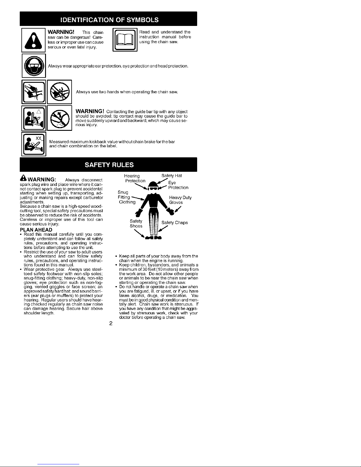
• Wear protective gear. Always use steel-
toed safety footwear with non-slip soles;
snug-fitting clothing; heavy-duty, non-slip
gloves; eye protection such as non-fog-
ging, vented goggles or face screen; an
approved safety hard hat; and sound barri-
ers (ear plugs or mufflers) to protect your
hearing. Regular usersshould havehear-
ing checked regularly as chain saw noise
can damage hearing. Secure hair above
shoulder length.
Hearing Safety Hat
Protection _Eye
"_1_1 qMpid_ Protection
Snug
Fittin Heavy Duty
Clothing Gloves
Safety Safety Chaps
Shoes
Keep all parts of your body away from the
chain when the engine is running.
Keep children, bystanders, and animals a
minimum of 30 feet (10 meters) away from
the work area. Do not allow other peopie
or animals to be near the chain saw when
starting or operating the chain saw.
Do not handle or operate a chain saw when
you are fatigued, ill, or upset, or if you have
taken alcohol, drugs, or medication. You
must be in good physical condition and men-
tally alert. Chain saw work is strenuous. If
you have any condition that might be aggra-
vated by strenuous work, check with your
doctor before operating a chain saw.
Page 3

• Carefullyplanyoursawthgoperationinad-
vance.Donotstartcuttinguntilyouhavea
clearworkarea,securefooting,and,ifyou
arefellingtrees,aplannedretreatpath.
OPERATE YOUR SAW SAFELY
• Do not operate a chain saw with one hand.
Serious injury to the operator, helpers, by-
standers or any combination of these per-
sons may result from one-handed opera-
tion. A chain saw is intended for
two-handed use.
• Operate the chain saw only in a wetbventi-
lated outdoor area.
• Do not operate saw from a ladder or in a
tree.
• MakesurethechainwiH not makecontact
with any object while starting the engine.
Never try to start the saw when the guide
bar is in a cut.
• Do not put pressure on the saw at the end
of the cut. Applying pressure can cause
you to lose control when the cut is com-
pleted.
• Stop the engine before setting the saw
down.
• Do not operate a chain saw that is dam-
aged, improperly adjusted, or not com-
pletely and securely assembled. Always
replace bar, chain, hand guard, or chain
brake immediately if it becomes damaged,
broken or is otherwise removed.
• With the engine stopped, hand carry the
chain saw with the muffler away from your
body, and the guide bar and chain to the
rear, preferably covered with a scabbard.
MAINTAIN YOUR SAW IN GOOD
WORKING ORDER
• Have all chain saw service performed by a
qualified service dealer with the exception
of the items listed in the maintenance sec-
tion oftMs manual. Forexample, if improp-
er tools are used to remove or hold the fly-
wheel when servicing the clutch, structura]
damage to the flywheel can occur and
cause the flywheel to burst.
• Make certain the saw chain stops moving
when the throttle trigger is released. For
correction, refer to CARBURETOR AD_
JUSTMENTS.
• Never modify your saw in any way.
• Keep the handles dry, clean, and free of oil
or fuel mixture.
• Keep fuel and oil caps, screws, and fas-
teners securely tightened.
• Use only Poulan_; accessories and re-
placement parts as recommended.
HANDLE FUEL WITH CAUTION
• Do not smoke while handling fuel or while
operating the saw.
• Eliminate all sources of sparks or flame in
the areas where fuel is mixed or poured.
There should be nosmoking, open flames,
orworkthat could cause sparks. Allow en-
gine to cool before refueling.
• Mix and pour fuel in an outdoor area on
bare ground; store fuel in a cool, dry, well
ventilated place; and use an approved,
marked container for all fuel purposes.
Wipe up all fuel spills before starting saw.
• Move at least 1g feet (3 meters) from fuel-
ing site before starting engine.
• Turn the engine off and let saw coo] in a
non-combustible area, not on dry leaves,
straw, paper, etc. Slowly remove fuel cap
and refuel unit.
• Storethe unit and fuetin an area wherefuel
vapors cannot reach sparks or open
flames from water heaters, electric motors
or switches, furnaces, etc.
KICKBACK
_I_WARNING: Avoid kickback which
can result in serious injury. Kickback is the
backward, upward or sudden forward motion
of the guide bar occurring when the saw
chain near the upper tip of theguide bar con-
tacts any object such as a log or branch, or
when the wood closes in and pinches the
saw chain in the cut. Contacting a foreign ob-
ject in the wood can also result in loss of
chain saw control.
• Rotational Kickback can occur when the
moving chain contacts an object at the up-
per tip of the guide bar. This contact can
cause the chain to dig into the object,
which stops the chain for an instant. The
result is a lightning fast, reverse reaction
which kicks the guide bar up and back to-
ward the operator.
• Pinch-Kickbackcan occur when the the
wood closes in and pinches the moving
saw chain in the cut along the top of the
guide bar and the saw chain is suddenly
stopped. This sudden stopping of the
chain results in a reversal of the chain
force used to cut wood and causes the
saw to move in the opposite direction of the
chain rotation. The saw is driven straight
back toward the operator.
• Pull-In can occur when the moving chain
contacts a foreign object in the wood in the
cut along the bottom of the guide bar and the
saw chain is suddenly stopped. This sudden
stopping pulls the saw forward and away
from the operator and could easily cause the
operator to lose contrc4 of the saw.
Avoid Pinch-Kickback:
• Be extremely aware of situations or ob-
structions that ca n ca use material to pinch
the top of or otherwise stop the chain.
• Do not cut more than one log at a time.
• Do not twist the saw as the bar is with-
drawn from an undercut when bucking.
Avoid Pull-In:
• Always begin cutting with the engine at full
speed and the saw housing against wood.
• Use wedges made of plastic or wood.
Never use metal to hold the cut open.
, _i,_/_;_ K ckback Path
Page 4
ClearTheWorkingArea
REDUCE THE CHANCE OF
KICKBACK
• Recognize that kickback can happen.
With a basic understanding of kickback,
you can reduce the element of surpbse
which contributes to accidents.
• Never let the moving chain contact any ob_
ject at the tip of the guide bar.
• Keep the working area free from obstruc-
tions such as othertrees, branches, rocks,
fences, stumps, etc. Eliminate or avoid
any obstruction that your saw chain could
hit while you are cutting. When cutting a
branch, do not let the guide bar contact
branch or other objects around it.
• Keep your saw chain sharp and properly
tensioned. A loose or dull chain can in-
crease the chance of kickback occurring.
Follow manufacturer's chain sharpening
and maintenanceinstructions. Checkten-
sion at regular intervals with the engine
stopped, never with the engine running.
Make sure the chain brake nuts are se-
curely tightened after tensioning the chain.
• Begin and continue cutting at full speed. If
the chain is moving at a slower speed,
there is greater chance of kickback occur-
ring.
• Cut one log at a time.
• Use extreme caution when re-entering a
previous cut.
• Do not attempt cuts starting with the tip of
the bar (plunge cuts).
• Watch for shifting logs or other forces that
could close a cut and pinch or fall into
chain.
• Use the Reduced-Kickback Guide Bar
and Low-Kickback Chain specified for
your saw.
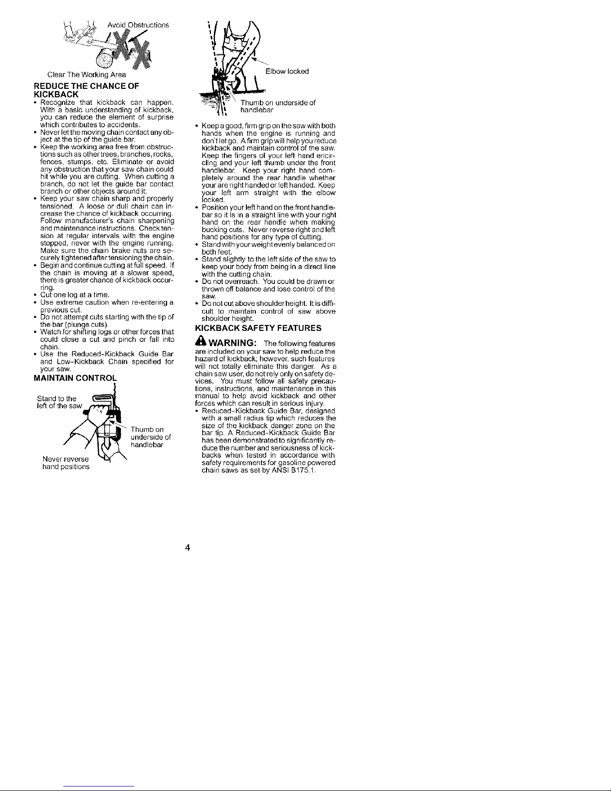
MAINTAIN CONTROL
Stand tothe
left ofth_ _ Thumb on
Neverreverse _Nhandlebar
hand positions
underside of
Elbow locked
Thumb on underside of
handlebar
• Keep a good, firm grip on the saw with both
hands when the engine is running and
don't let go. A firm gd p will help you reduce
kickback and maintain control of the saw.
Keep the fingers of your left hand encir-
cling and your left thumb under the front
handlebar. Keep your right hand com-
pletely around the rear handle whether
your are right handed or left handed. Keep
your left arm straight with the elbow
locked.
• Position your left hand on the front handle-
bar so it is in a straight line with your right
hand on the rear handle when making
bucking cuts. Never reverse dght and left
hand positions for any type of cutting.
• Stand with your weight evenly balanced on
both feet.
• Stand slightly to the left side of the saw to
keep your body from being in a direct line
with the cutting chain.
• Do not overreach. You could be drawn or
thrown off balance and lose control of the
Saw.
• Donotcutaboveshoulderheight. Itisdiffi-
cult to maintain control of saw above
shoulder height.
KICKBACK SAFETY FEATURES
_ WARNING: The followingfeatures
are included on your saw to help reduce the
hazard of kickback; however, such features
will not totally eliminate this danger As a
chain saw user, do not rely only on safety de-
vices. You must follow all safety precau-
tions, instructions, and maintenance in this
manual to help avoid kickback and other
forces which can result in serious injury.
• Reduced-Kickback Guide Bar, designed
with a small radius tip which reduces the
size of the kickback danger zone on the
bar tip. A Reduced-Kickback Guide Bar
has been demonstrated to significantly re-
duce the number and seriousness of kick-
backs when tested in accordance with
safety requirements for gasoline powered
chain saws as set by ANSI BI75.1.
Page 5
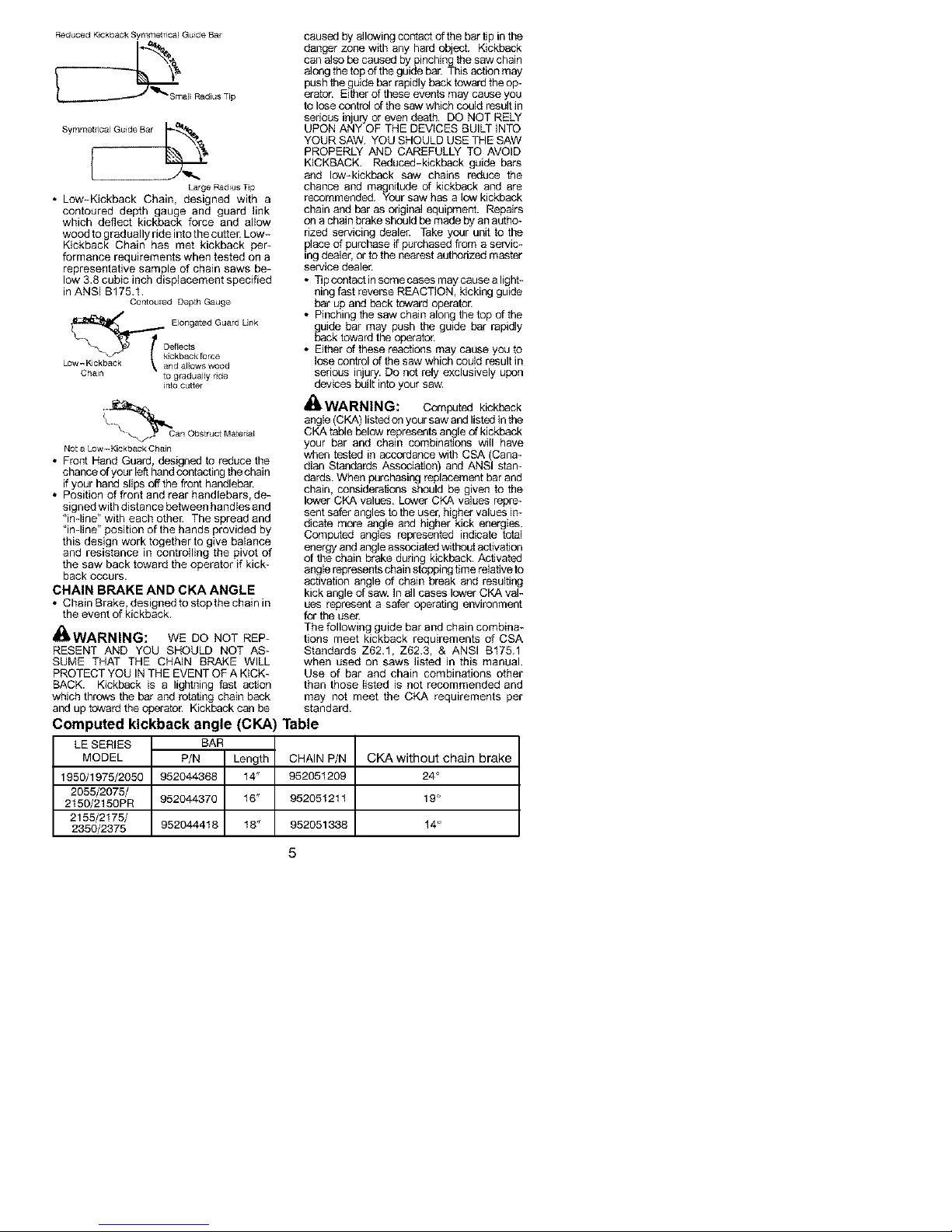
ReducedKickbackSymmetricalGuideBar
al_RadiusTip
SymmetricalGuideBar_-_'_
BargeRadiusTip
• Low-KickbackChain,designedwitha
contoureddepthgaugeandguardlink
whichdeflectkickbackforceandallow
woodtograduallyrideintothecutter.Low-
KickbackChainhasmetkickbackper-
formancerequirementswhentestedona
representativesampleofchainsawsbe-
low3.8cubicinchdisplacementspecified
inANSIB175.1.
ContouredDepthGauge
DElongatedGuardLink
Low-Kickback_andallowswood
Chain tograduallyride
intocutter
_Can ObstructMateria_
NotaLow-KickbackChain
• FrontHandGuard,designedtoreducethe
chanceofyourlefthandcontactingthechain
ifyourhandslipsoffthefronthandlebar.
• Positionoffrontandrearhandlebars,de-
signedwithdistancebetweenhandlesand
"inqine" with each other The spread and
"inqine" position of the hands provided by
this design work together to give balance
and resistance in controlling the pivot of
the saw back toward the operator if kick-
back occurs.
CHAIN BRAKE AND CKA ANGLE
• Chain Brake, designed to stop the chain in
the event of kickback.
_WARNING: WE DO NOT REP-
RESENT AND YOU SHOULD NOT AS-
SUME THAT THE CHNN BRAKE WILL
PROTECT YOU IN THE EVENT OF A KICK-
BACK. Kickback is a lightning fast acflon
which throws the bar and rotating chain back
and up toward the operator. Kickback can be
Computed kickback angle (CKA)
LE SERIES
MODEL
1950/1975/2050
2055/2075/
2150/2150PR
2155/2t75/
2350/2375
BAR
P/N Length
952044363 14"
952044370 16"
952044418 18" 952051338
caused by allowing contact of the bar tip in the
danger zone with any hard object. Kickback
can also be caused by pinching the saw chain
along the top of the guide bar. This action may
push the guide bar rapidly back toward the op-
erator. Either of these events may cause you
to lose control of the saw which could result in
serious injury or even death. DO NOT RELY
UPON ANY OF THE DEVICES BUILT INTO
YOUR SAW. YOU SHOULD USE THE SAW
PROPERLY AND CAREFULLY TO AVOID
KICKBACK. Reduced-kickback guide bars
and low-kickback saw chains reduce the
chance and magnitude of kickback and are
recommended. Your saw has a low kickback
chain and bar as original equipment. Repairs
on a chain brake should be made by an autho-
rized servicing dealer. Take your unit to the
place of purchase if purchased from a servic-
ing dealer, or to the nearest authorized master
service dealer.
• Tip contact in some cases may cause a light-
ning fast reverse REACTION, kicking guide
bar up and back toward operator.
• Pinching the saw chain along the top of the
guide bar may push the guide bar rapidly
back toward the operator.
• Either of these reactions may cause you to
lose control of the saw which could result in
serious injury. Do not rely exclusively upon
devices built into your saw.
,,_ WARNING: Computed kickback
angle (CKA) listed on your saw and listed in the
CKA table below represents angle of kickback
your bar and chain combinations witl have
when tested in accordance with CSA (Cana-
dian Standards Association) and ANSI stan-
dards. When purchasing replacement bar and
chain, considerations should be given to the
lower CKA values. Lower CKA values repre-
sent safer angles to the user, higher values in-
dicate more angle and higher kick energies.
Computed angles represented indicate total
energy and angle associated without activation
of the chain brake during kickback. Activated
angle represents chain stopping time relative to
activation angle of chain break and resulting
kick angle of saw. In all cases lower CKA val-
ues represent a safer operating environment
for the user.
The following guide bar and chain combina-
tions meet kickback requirements of CSA
Standards Z62.1, Z62.3, & ANSI B175.1
when used on saws listed in this manual.
Use of bar and chain combinations other
than those tisted is not recommended and
may not meet the CKA requirements per
standard.
Table
CHAIN P/N
952051209
952051211
CKA without chain brake
24 °
19 °
14°
Page 6
NOTE: If this saw is to be used for com-
mercial Iogging, a chain brake is required
and shall not be removed or otherwise dis-
abled to comply with Federal OSHA Regula-
tions for Commercial Logging.
SAFETY NOTICE: Exposure to vibrations
through prolonged use of gasoline powered
hand tools could cause blood vessel or nerve
damage in the fingers, hands, and joints of
people prone to circulation disorders or
abnormal swellings. Prolonged use in cold
weather has been linked to blood vessel
damage in otherwise healthy beop_e. If
symptoms occur such as numbness, psin,
loss of strength, cbenge in skin color or texture,
or loss of feelieg in the fingers, hand& or joints,
discontinue the use of this tool and seek
medical attention. An antiwibration system
does not guarantee the avc_dance of these
problems. Users who operate power tools on
a confinual and regular basis must monitor
closely their physical condition and the
condition of this tool.
SPECIAL NOTICE: Your saw is equipped
with a temperaturelimiting muffler and spark
arresting screen which meets the
requirements of California Codes 4442 and
4443. AH U.S. forest land and the states of
California, idaho, Maine, Minnesota, New
Jersey, Oregon, and Washington require by
law that many internal combustion engines
to be equipped with a spark arresting screen.
Ifyou operate a cbein saw in a state or locale
where such regulations exist, you are legally
responsible for mak/tak/ing the operating
condition of these parts. Failure to do so is
a violation of the law. Refer to the SERVICE
section for maintenance of the spark
arresting screen.
Failureto follow all Safety Rules and Precau-
tions can result in serious injury. If situations
occur which are not covered in this manual,
use care and good judgement. If you need
assistance, contact your authorized service
dealer or call 1-800-554-6723.
STANDARDS: This saw is listed by Under-
writer's Laboratories, Inc., in accordance with:
ANSI B175,1-200g American National
Standards for Gasoline-Powered Chain
Saws - Safety Requirements
CSA Z62.1-03 Chain Saws ~ Occupational
Health and Safety
CSA Z62.3-g6 Chain Saw Kickback Occu-
pational Health and Safety
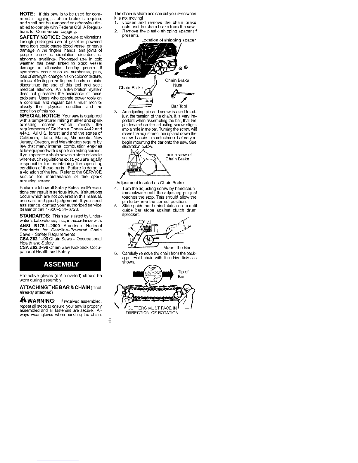
The chain is sharp and can cut you even when
it is not moving!
1. Loosen and remove the chain brake
nuts and the chain brake from the saw.
2. Remove the plastic shipping spacer (if
present).
Ch Nuts
3. An adjusting #n and screw is used to ad-
just the tension of the chain. It is very im-
portant when assembling the bar, that the
i_n located on the adjusting screw atigns
into a hole in the bar. Turning the screw wi]i
move the adjustment pin up and down the
screw. Locate this adjustment before you
begin mounting the bar onto the saw. See
illustration below.
f C_ain Brake
Adjustment located on Chain Brake
4. Turn the adjusting screw by hand coun-
terclockwise until the adjusting pin just
touches the stop. This should allow the
pin to be near the correct position.
5. Slide guide bar behind clutch drum until
guide bar stops against clutch drum
sprocket.
6. Cardully remove the chain from the pack-
age. Mold chain with the drive links as
shown.
Location of shipping spacer
a_ Chain Brak_e
Bar Too]
Inside view of
Protective gloves (not provided) should be
worn during assembly.
ATTACHING THE BAR & CHAIN (If not
already attached)
_]kWARNING: If received assembled,
repeat all steps to ensure your saw is probedy
assembled and all fasteners are secure. Al-
ways wear gloves when handling the chain.
DIIRECTION OF FLOTATION
?Sp of
Bar
Page 7
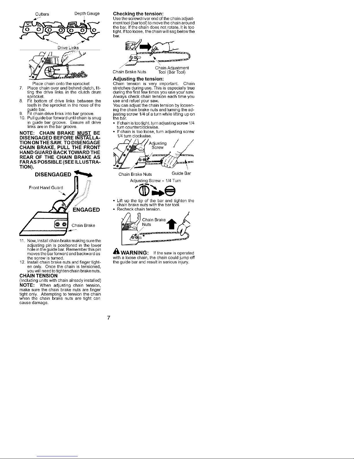
Cutters Depth Gauge
Drive Links
Place chain onto the sprocket
7. Place chain over and behind clutch, fit-
ting the drive links in the clutch drum
sprocket.
& Fit bottom of drive links between the
teeth in the sprocket in the nose of the
guide bar.
9. Fit chain drive links into bar groove.
10. Pull guide bar forward until chain is snug
in guide bar groove. Ensure all drive
links are in the bar groove.
NOTE: CHAIN BRAKE MUST BE
DISENGAGED BEFORE INSTALLA-
TION ON THE SAW. TO DISENGAGE
CHAIN BRAKE, PULL THE FRONT
HAND GUARD BACK TOWARD THE
REAR OF THE CHAIN BRAKE AS
FARAS POSSIBLE (SEE ILLUSTRA-
TION).
Front Hand Guard
DISENGAGED _
ENGAGED
Chain Brake
Checking the tension:
Use the screwdriver end of the chain adjust-
ment tool (bar tool) to move the chain around
the bar. If the chain does not rotate, it is too
tight. If too loose, thechain will sag below the
bar.
Chain Brake Nuts Tool (Bar Tool)
Adjusting the tension:
Chain tension is very important. Chain
stretches during use. This is especially true
during the first few times you use your saw.
Always check chain tension each time you
use and refuel your saw.
You can adjust the chain tension by loosen-
ing the chain brake nuts and turning the ad-
justing screw 1/4 of a turn while lifting up on
the bar.
• If chain is tootight, turn adjusfing screw 1/4
turn counterclockwise.
• If chain is too loose, turn adjusting screw
1/4 turn clockwise.
f-_/_/Adjusting / J
® O Screw
Chain Brake Nuts Guide Bar
Adjusting Screw - 1/4 Turn
• Lift up the tip of the bar and tighten the
chain brake nuts with the bar tool.
• Recheck chain tension.
Chain Brake
1I. Now, install chain brake making surethe
adjusting pin is positioned in the lower
hole in the guide bar. Remember this pin
moves the bar forward and backward as
the screw is turned.
12. Install chain brake nuts and finger tight-
en only. Once the chain is tensioned,
you will need to tighten chain brake nuts.
CHAIN TENSION
(Including units with chain already installed)
NOTE: When adjusting chain tension,
make sure the chain brake nuts are finger
tight only. Attempting to tension the chain
when the chain brake nuts are tight can
cause damage.
Nuts
,t&
WARNING: if the saw is operated
with a loose chain, the chain could jump off
the guide bar and result in serious injury.
Page 8
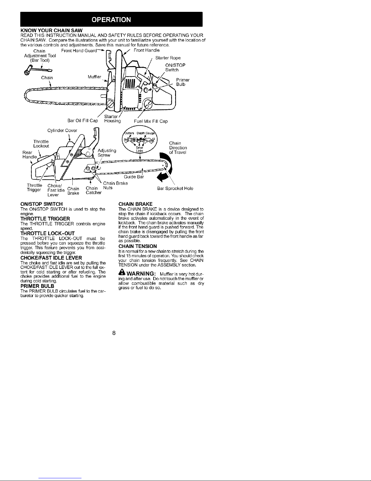
KNOW YOUR CHAIN SAW
READ THIS iNSTRUCTION MANUAL AND SAFETY RULES BEFORE OPERATING YOUR
CHAIN SAW. Compare the illustrations with your unit to familiarize yourseft with the location of
the various controls and adjustments. Save this manual for future reference.
Chain Front Hand Guard -'_- f'_J Front Handle
Adjustment Tool I I_"_I I¢" Starter Rope
BorToo, Ibr- /
Chain Muffler [ _._ _€//_ BPd_er
Bar Oil Fill Cap Housing Fuel Mix Fill Cap
Cylinder Cover
Throttle
Lockout o
Reari_ _
Hand
clUStfflg o%Civ°'l
Chain
Throttle Choke/
Trigger Fast Idle Chain
ON/STOP SWITCH
The ON/STOP SWITCH is used to stop the
engine.
THROTTLE TRIGGER
The THROTTLE TRIGGER controls engine
speed.
THROTTLE LOCK-OUT
The THROTTLE LOCK-OUT must be
pressed before you can squeeze the throttle
trigger. This feature prevents you from acci-
dentally squeezing the trigger.
CHOKE/FAST IDLE LEVER
The choke and fast idle are set by pulling the
CHOKE/FAST IDLE LEVER out to the full ex-
tent for cc4d. starling or after refueling. The
choke prowdes additional fuel to the engine
during cold starting.
PRIMER BULB
The PRIMER BULB circulates fuel to the car-
buretor to provide quicker starting.
Lever Brake
Chain Nuts Bar Sprocket Hole
Catcher
Chain Brake
CHAIN BRAKE
The CHAIN BRAKE is a device designed to
stop the chain if kickback occurs. The chain
brake activates automatically in the event of
kickback. The chain brake activates manually
if the front hand guard is pushed forward. The
chain brake is disengaged by puffing the front
hand guard back toward the front handle as far
as possible.
CHAIN TENSION
it is normal for a new chain to stretch during the
first 15 minutes of operation. You should check
your chain tension frequently. See CHAIN
TENSION under the ASSEMBLY section.
_I_WARNING: Muffler is very hotdur-
fflg and after use. Do not touch the m uftJer or
allow combustible mateda] such as dry
grass or fuel to do so.
Page 9
_lk WARNING: Remove fuel cap slow-
ly when refueling.
FUELING ENGINE
This engine is certified to operate on un-
leaded gasoline. Before operation, gasoline
must be mixed with a good quality synthetic
2-cycle aff-cooled engine oil designed to be
mixed ata ratioof40:f. Poulan/Weed Eater
brand synthetic oil is recommended. A40:1
ratio is obtained by mixthg 3.2 ounces (95 ml)
of oil with 1 gallon (4 liters) of unleaded gaso-
line. Included with this saw ls a 3.2 ounce ccm
tainer of PouJan/Weed Eater brand synthetic
oil. Pour the enlJre contents of this ccntainer
into 1 gallon of gasoline to achieve the proper
fuel mixture.
DO NOT USE automotive or marine oil.
These oils will cause engine damage. When
mixing fuel follow the instructions pdnted on
the container. Always read and follow the
safety rules listed under HANDLE FUEL
WiTH CAUTION.
BAR AND CHAIN LUBRICATION
The bar and chain requffe continuous lubrb
cation. Lubrication is provided by the auto-
matic oiler system when the oil tank is kept
filled. Lack of oil will quickly ruin the bar and
chain. Too little oil will cause overheating
shown by smoke coming from the chain and/
or discoloration of the bar.
In freezing weather oil will thicken, making it
necessary to thin bar and chain oil with a
small amount (5 to 10%) of #1 Diesel Fuel or
kerosene. Bar and chain oil must be free
flowing for the oil system to pump enough oil
for adequate lubrication.
Genuine Poulan® bar and chain oil is recom-
mended to protect your unit against exces-
sive wear from heat and friction. Poulan®
oil resists high temperature thinning.
If Poulan® bar and chain oil is not available,
use a good grade SAE 30 oil.
• Never use waste oil for bar and chain lubri-
cation.
• Always stop the engine before removing
the oil cap.
IMPORTANT
Experience indicates that aicohot-blended
fuels (called gasohol or using ethanol or
methanol) can attract moisture which leads
to separation and formation of acids during
storage. Acidic gas can damage the fuel
system of an engine while in storage. To
avoid engine problems, the fuel system
should be emptied before storage for 30
days or longer. Drain thegas tank, start the
engine and let it run until the fuel lines and
carburetor are empty. Use fresh fuel next
season. See STORAGE section for addi-
tional information.
AIL
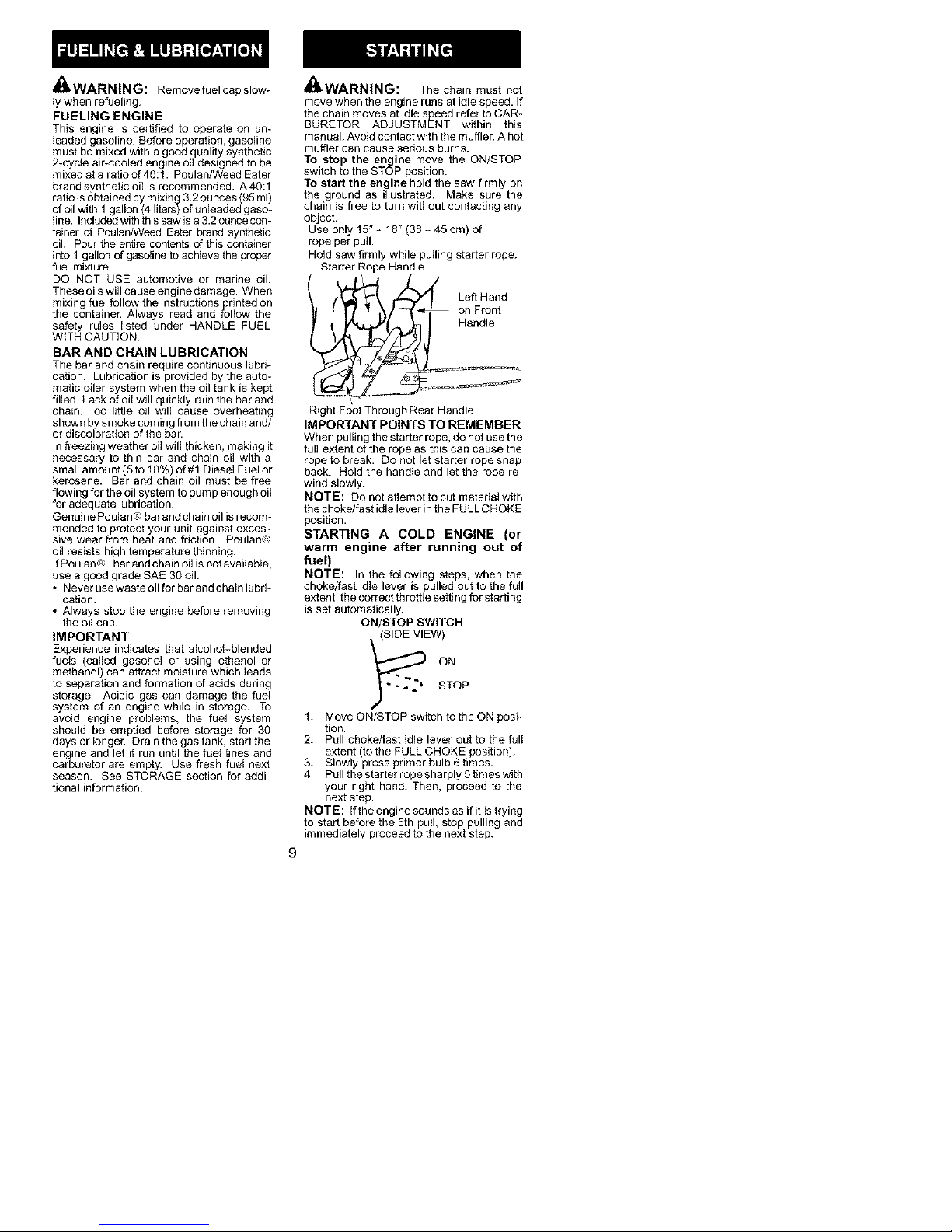
oWARNING: The chain must not
move when the engine runs at idle speed. If
the chain moves at idle speed refer to CAR-
BURETOR ADJUSTMENT within this
manual Avoid contact with the muffler. A hot
muffler can cause serious burns.
To stop the engine move the ON/STOP
switch to the STOP position.
To start the engine hold the saw firmly on
the ground as illustrated. Make sure the
chain is free to turn without contacting any
object.
Use only 15" - 18" (38 - 45 cm) of
rope per pull.
Hold saw firmly while pulling starter rope.
Starter Rope Handle
Left Hand
on Front
Handle
Right Foot Through Rear Handle
IMPORTANT POINTS TO REMEMBER
When pulling the starter rope, do not use the
full extent of the rope as this can cause the
rope to break. Do not let starter rope snap
back. Hold the handle and let the rope re-
wind slowly.
NOTE: Do not attempt to cut material wdh
the choke/fast idle lever Jn the FULL C HOKE
position.
STARTING A COLD ENGINE (or
warm engine after running out of
fuel)
NOTE: In the following steps, when the
choke/fast idle lever is pulled out to the full
extent, the correct throttle setting for starting
is set automatically.
ON/STOP SWITCH
(SIDE VIEW)
?oP
1. Move ON/STOP switch to the ON posi-
tion.
2. Pull choke/fast idle lever out to the full
extent (to the FULL CHOKE position).
3. Slowly press primer bulb 6 times.
4. Pull the starter rope sharply 5 times with
your right hand. Then, proceed to the
next step.
NOTE: If the engine sounds as if it is trying
to start before the 5th pull, stop pulling and
immediately proceed to the next step.
Page 10
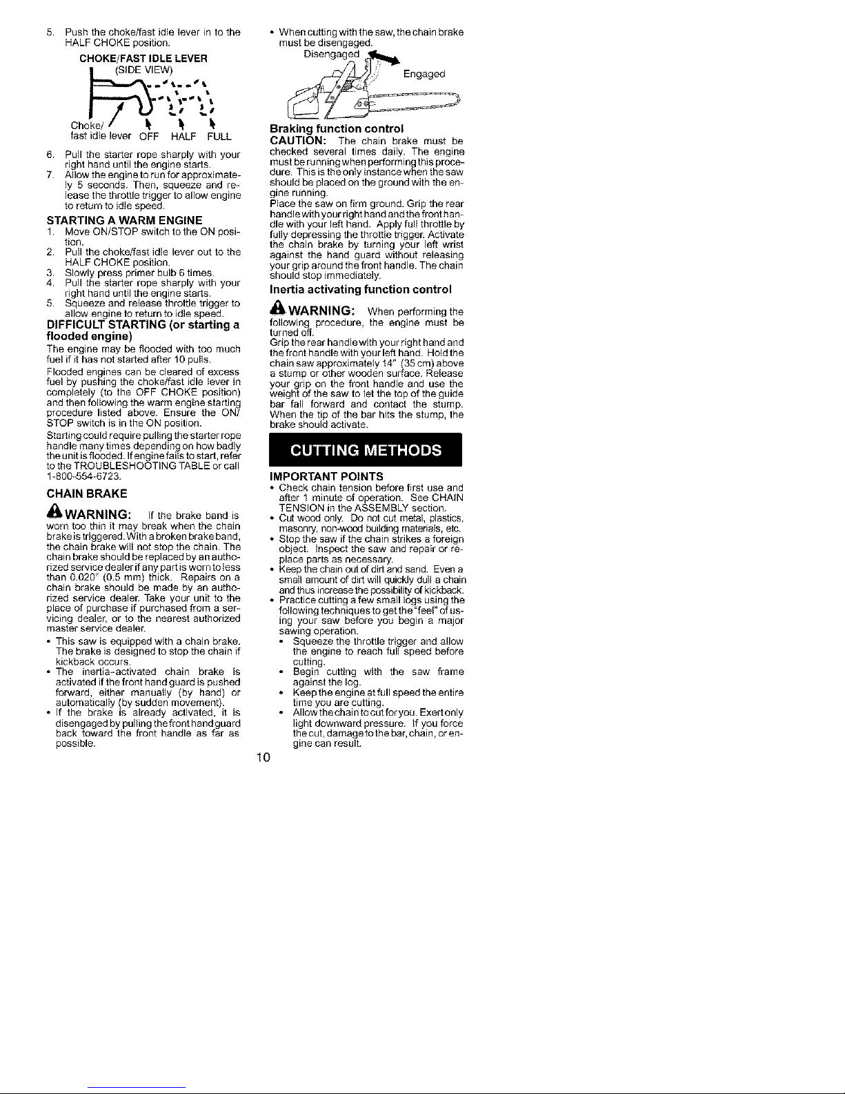
5. Pushthechoke/fastidleleverintothe
HALFCHOKEposition.
CHOKE/FAST IDLE LEVER
o_,IEW)
• When cutting with the saw, the chain brake
must be disengaged.
Disengaged _
I I
Ch k
fast idle lever OFF HALF FULL
6. Pull the starter rope sharply with your
dght hand until the engine starts.
7. Allow the engine to run for approximate-
ly 5 seconds. Then, squeeze and re-
lease the throttle trigger to allow engine
to return to idle speed.
STARTING A WARM ENGINE
1. Move ON/STOP switch to the ON posi-
tion.
2. Pull the choke/fast idle lever out to the
HALF CHOKE position.
3. Slowly press primer bulb 6 times.
4. Pull the starter rope sharply with your
dght hand until the engine starts.
5. Squeeze and release throttle trigger to
allow engine to return to idle speed.
DIFFICULT STARTING (or starting a
flooded engine)
The engine may be hooded with too much
fuel if it has not started after 10 pulls.
Flooded engines can be cleared of excess
fuel by pushing the choke/fast idle lever in
completely (to the OFF CHOKE position)
and then following the warm engine starting
procedure listed above. Ensure the ON/
STOP switch is in the ON position.
Starting could require pulling the starter rope
handle many times depending on how badly
the unit is flooded. If engine fails to start, refer
to the TROUBLESHOOTING TABLE or call
1-500-554-6723.
CHAIN BRAKE
_kWARNING: If the brake band is
worn too thin it may break when the chain
brake is triggered. With a broken brake band,
the chain brake will not stop the chain. The
chain brake should be replaced by an autho-
rized service dealer if any part is worn to less
than 0.020" (0.5 ram) thick. Repairs on a
chain brake should be made by an autho-
rized service dealer. Take your unit to the
place of purchase if purchased from a ser-
vicing dealer, or to the nearest authorized
master service dealer.
• This saw is equipped with a chain brake.
The brake is designed to stop the chain if
kickback occurs.
• The inertia-activated chain brake is
activated if the front hand guard is pushed
forward, either manually (by hand) or
automatically (by sudden movement).
• If the brake is already activated, it is
disengaged by pulling the front hand guard
back toward the front handle as far as
possible.
_iili
Braking function control
CAUTION: The chain brake must be
checked several times daily. The engine
must be running when performing this proce-
dure. This is the only instance when the saw
should be placed on the ground with the en-
gine running.
Place the saw on firm ground. Grip the rear
handle with your right hand and the front ham
die with your left hand. Apply full throttle by
fully depressing the throttle trigger. Activate
the chain brake by turning your left wrist
against the hand guard without releasing
your grip around the front handle. The chain
should stop immediately.
Inertia activating function control
_kWARNING: When performing the
following procedure, the engine must be
turned off.
Grip the rear handlewith your right hand and
the front handle with your left hand. Hold the
chainsawapproximatetyf4" (35cm above
a stump or other wooden sur ace. Re ease
your grip on the front handle and use the
weight of the saw to let the top of the guide
bar fall forward and contact the stump.
When the tip of the bar hits the stump, the
brake should activate.
IMPORTANT POINTS
• Check chain tension before first use and
after f minute of operation. See CHAIN
TENSION in the ASSEMBLY section.
• Cut wood only. Do not cut metal, plastics,
masonry, non-wood building materials, etc.
• Stop the saw if the chain strikes a foreign
object. Inspect the saw and repair or re-
place parts as necessary.
• Keepthecbain out of dirt and sand. Even a
small amount of dirt will quickly dull a chain
and thus increase the possibility of kickback.
• Practice cutting a few small logs using the
following techniques to get the "feel" of us-
ing your saw before you begin a major
sawing operation.
• Squeeze the throttle trigger and allow
the engine to reach full speed before
cutting.
• Begin cutting with the saw frame
against the log.
• Keep the engine at full speed the entire
time you are cutting.
• AIIowthechaintocutforyou. Exertonly
light downward pressure, tf you force
the cut, damage to the bar, chain, or en-
gine can result.
10
Page 11
• Release the throttle trigger as soon as
the cut is completed, allowing the en-
gine to idle. If you run the saw at full
throtfie without a cuttthg load, unneces-
sary wear can occur to the chain, bar,
and engine. It is recommended that
the engine not be operated for lon-
ger than 30 seconds at full throttle.
• To avoid losing controlwhen cut is com-
plete, do not put pressure on saw at end
of cut.
• Stop the engine before setting the saw
down after cutting.
TREE FELLING TECHNIQUES
_I_WARNING: Check for broken or
dead branches which can fatl while cutfing
causing serious injury. Do not cut near bui_d-
thgs or etectboal wires Jfyou do not know the
direction oftreefall, norcut at night since you
will not be ale to see well, nor during bad
weathersuch as rain, snow, or strong winds,
etc. If the tree makes contact with any utility
line, the utility company should be notified
immediately.
• Carefully plan your sawing operation in ad-
vance.
• Cleartheworkarea. You needacleararea
all around the tree so you can have secure
footing.
• The chain saw operator should keep on
the uphill side of the terrain as the tree is
likely to roll or slide downhill after it is felled.
• Study the natural conditions that can cause
the tree to fall in a particular direction.
Natural condifions that can cause a tree to
fall in a parficular direction include:
• The wind direction and speed.
• The lean of the tree. The lean of a tree
might not be apparent due to uneven or
sloping terrain. Use a piumb or level to de-
termine the direcfion of tree lean.
• Weight and branches on one side.
• Surrounding trees and obstacles.
Look for decay and rot. If thetrunk is rotted,
it can snap and fall toward the operatoE
Check for broken or dead branches which
can fall on you while cutting.
Make sure there is enough room for the tree
to fall. Maintain a distance of 2=1/2 tree
lengths from the nearest person or other ob-
jects. Engine noise can drown out a warning
call.
Remove dirt, stones, loose bark, nails, sta-
ples, and wire from the tree where cuts are to
be made.
Plan a clear retreat path to the rear and diag-
onal to the line of fall.
Plan a clear retreat path
_'"÷- "O" u,,,,,,+ - Direction of Fall
FELLING LARGE TREES
(6 inches (15 cm) in diameter or iarger)
The notch method is used to fell large trees.
A notch is cut on the side of the tree inthede-
sired direction of fall. After a felling cut is
made on the opposite side of tree, the tree
will tend to fall into the notch.
NOTE: If the tree has large buttress roots,
remove them before making the notch. If us-
ing saw to remove buttress roots, keep saw
chain from contacting ground to prevent dull-
ing of the chain.
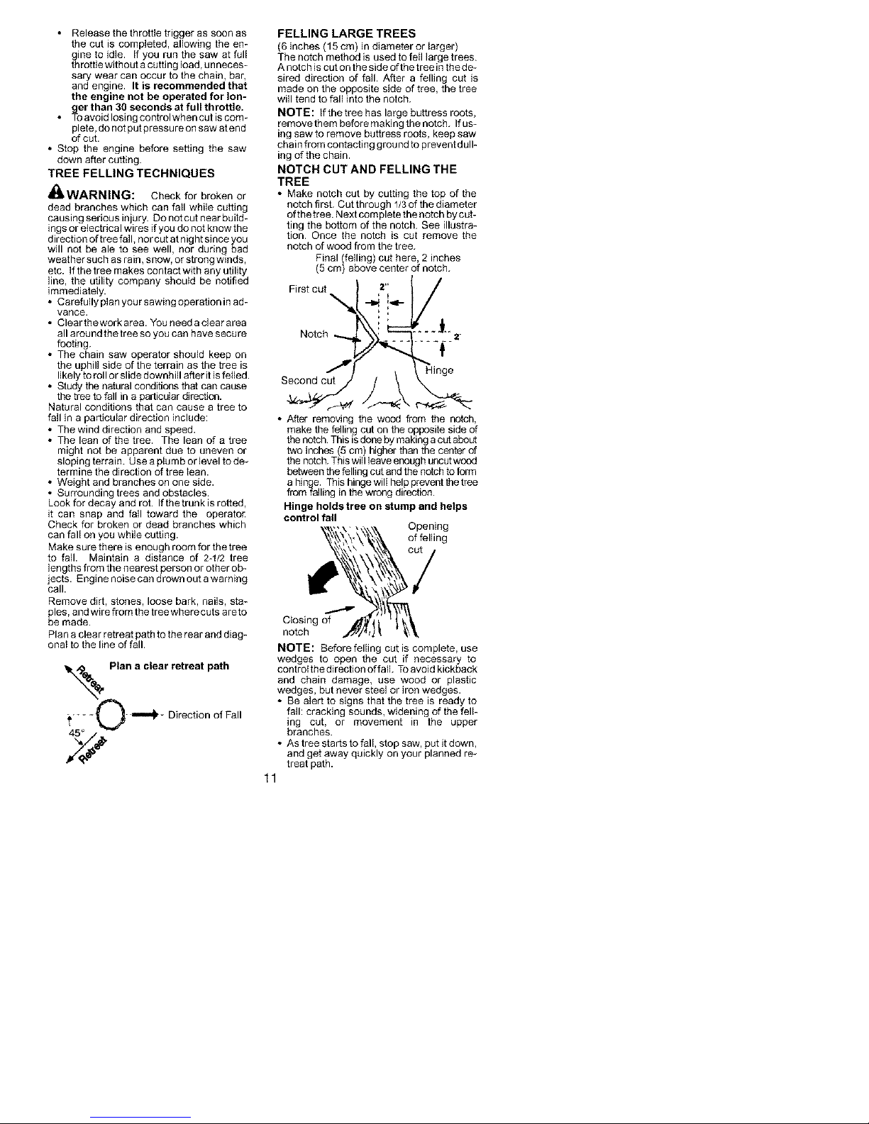
NOTCH CUT AND FELLING THE
TREE
• Make notch cut by cutting the top of the
notch first. Cut through 1/3 of the diameter
ofthetree. Next complete the notch bycut-
ting the bottom of the notch. See illustra-
tion. Once the notch is cut remove the
notch of wood from the tree.
Final (felling) cut here, 2 inches
(5 cm) above center of notch.
I/
Notch ....... _2"
Second cut
• After removing the wood from the notch,
make the felling cut on the opposite side of
the notch. This is done by making a cut about
two inches 5 cm) higher than the center of
the notch. Th s w eave enough uncut wood
between the felling cut and the notch to form
a hinge. This hinge will help prevent the tree
from falling in the wrong direction.
Hinge holds tree on stump and helps
control fall
Ctosing of
notch
NOTE: Before felling cut is complete, use
wedges to open the cut if necessary to
controtthedJrectJon of falL To avoid kickback
and chain damage, use wood or plastic
wedges, but never steel or iron wedges.
• Be alert to signs that the tree is ready to
fall: cracking sounds, widening of the fell-
ing cut, or movement in the upper
branches.
• As tree starts to fall, stop saw, put it down,
and get away quickly on your planned re-
treat path.
11
Opening
of felling
Page 12
• DO NOT cut down a partially fallen tree
with your saw. Be extremely cautious with
partially fallen trees that may be poorly
supported. When a tree doesn't fall com-
pletely, set the saw aside and pull down the
tree with a cable winch, block and tackle,
or tractor.
CUTTING A FALLEN TREE
(BUCKING)
Bucking is the term used for cutting a fallen
tree to the desired log size.
_ik WARNING: Do not stand on thelog
being cut. Any portion can roll causing loss
of footing and control. Do not stand downhill
of the log being cut.
IMPORTANT POINTS
• Cut only one log at a time.
• Cut shattered wood very carefully; sharp
pieces of wood could be flung toward opera-
ton
• Use a sawhorse to cut small logs. Never
allow another person to hold the log wMe
cutting and never hold the log with you r leg
or foot.
• Do not cut in an area where logs, limbs,
and roots are tangled such as in a blown
down area. Drag the logs into a clear area
before cutting by pulling out exposed and
cleared logs first.
TYPES OF CUTTING USED FOR
BUCKING
_kWARNING: tf saw becomes
pinched or hung in a log, don't try to force it
out. You ca n lose control of the saw resulting
in injury and/or damage to the saw. Stopthe
saw, drive a wedge of plastic or wood into the
cut until the saw can be removed easily. Re-
start the saw and carefully reenter thecut. To
avoid kickback and chain damage, do not
use a metal wedge. Do not attempt to restart
your saw when it is pinched or hung in a log.
Use a wedge to remove pinched saw
Turn
saw OFF and use a plastic or
wooden wedge to force cut open.
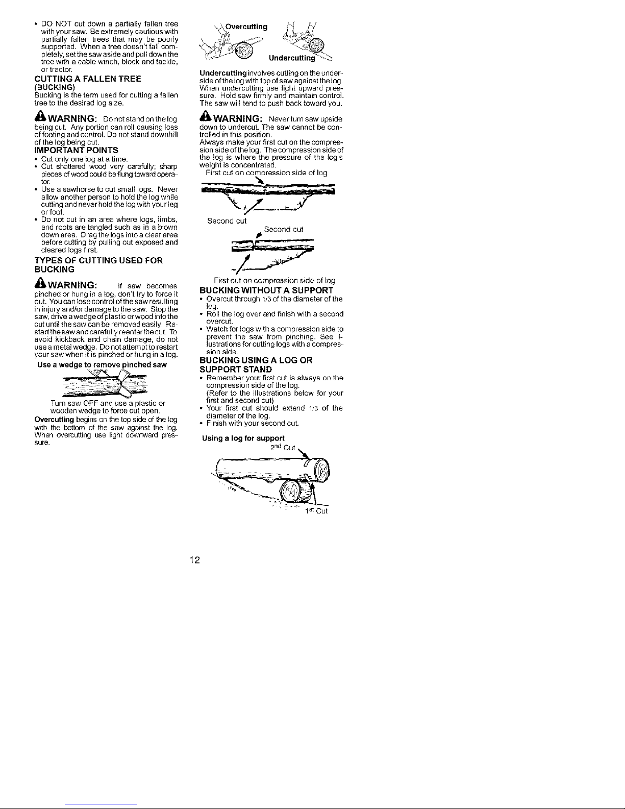
Overcutting begins on the top side of the log
with the bottom of the saw against the log.
When overcutting use light downward pres-
sure.
Undercutting involves cutting on the under-
side of the log with top of saw against the log.
When undercutting use light upward pres-
sure. Hold saw firmly and maintain control.
The saw will tend to push back toward you.
_k WARNING: Neverturnsawupside
down to undercut. The saw cannot be con-
trolled in this position.
Always make your first cut on the compres-
sion side oftheiog. Thecompression side of
the log is where the pressure of the log's
weight is concentrated.
First cut on co['npression side of log
Second cut
First cut on compression side of log
BUCKING WITHOUT A SU PPORT
• Overcut through 1/3 of the diarneter of the
log.
• Roll the log over and finish with a second
overcut.
• Watch for logs with a compression side to
prevent the saw from pinching. See il-
lustrations for cutting logs with a compres-
sion side.
BUCKING USING A LOG OR
SUPPORT STAND
• Remember your first cut is always onthe
compression side of the tog.
(Refer to the illustrations below for your
first and second cut)
• Your first cut should extend 1/3 of the
diameter of the log.
• Finish with your second cut.
Using a log for support
Second cut
2nd Cut
12
Page 13

_1 st Cut
Using a support stand
2 nd Cut
• Keep the tree between you and the chain.
Cut from the side of the tree opposite the
branch you are cutting.
• Remove larger, supppriJng branches with
the cutting techniques described in BUCK-
ING WITHOUT A SUPPORT
• Always use an overcut to cut small and free-
ly hanging limbs. Undercutting could cause
hmba to fail and pinch the saw.
PRUNING
,_kWARNING: Limit pruning to limbs
shoulder height or below. Do not cut if
branches are higher than your shoulder. Get a
professional to do the job.
• Make your first cut 1/3of the way through tbe
bottom of the limb.
• Next make a 2nd cut all the way through
the limb, Then cut a third overcut leaving a
1 to 2 inch (2.5 to 5 cm )collar from the truck
of the tree.
Third eut j_///
LIMBING AND PRUNING
,_I_WARNING: Bealertforandguard
against kickback. Do not atlow the moving
chain to contact any other branches or objects
at the nose of the guide bar when limbing or
pruning. Allowing such contact can result in
serious injury.
_WARNING: Never climb into a tree to
limb or prune. Do not stand on ladders, plat-
forms, a log, or Jnany position which can cause
you to lose your balance or control of the saw.
IMPORTANT POINTS
• Work slowly, keeping both hands firmly
gripped on the saw. Math_ain secure footing
and balance.
• Watch out for springpc4es. Springpoles are
small size limbs which can catch the saw
chain and whip toward you or pull you off bal-
ance. Use extreme caution when cutting
small size limbs or slender material
• Be alert for spbngback. Watch out for
branches that are bent or under pressure.
Avoid being struck by the branch or the
saw when the tension in the wood fibers is
released.
• Keep a clear work area. Frequently clear
branches out of the way to avoid tripling
over them.
LIMBING
• Always limb atree after it is cut down. Only
then can Ilmbing be done safely and prop-
erly.
• Leave the larger limbs underneath the felled
tree to support the tree as you work.
• Start at the base of the felled tree and work
toward the top, cutting branches and limbs.
Remove small limbs with one cut.
Collar
l i {l'i Becondcut_'l_ _J_
_4_]_ / _ Firstcut
Pruning technique
,I_WARNING: Disconnect the spark
plug before performing maintenance except
for carburetor adjustments.
We recommend atl service and adjustments
not listed in this manual be performed by an
authorized or Master Service Dealer.
MAINTENANCE SCHEDULE
Check:
Fuel medure level .... Before each use
Bar lubrication ....... Before each use
Chain tension ....... Before each use
Chain sharpness .... Before each use
For damaged parts .. Before each use
For loose caps ...... Before each use
For loose fasteners... Before each use
For loose parts ...... Before each use
Inspect and Clean:
Bar ................ Before each use
Complete saw ....... After each use
Air filter ............. Every 5 hours*
Chain brake ........ Every 5 hours*
Spark arresting screen
and muffler ......... Every 25 hours*
Replace spark plug . Yearly
Replace fuel filter... Yearly
* Hours of Operation
13
Page 14

AIR FILTER
CAUTION: Do not clean filter ingasoline
or other flammable solvent to avoid creating
a fire hazard or producing harmful evapora-
tive emissions.
Cleaning the air filter:
A dirty air filter decreases engine perform-
ance and increases fuel consumption and
harmful emissions. Always clean after every
5 hours of operation.
1. Loosen 3 screws on cylinder cover.
2. Remove cylinder cover.
3. Remove air filter.
4. Clean the fflr filter using hot soapywater.
Rinse with clean cool water. Air dry
completely before rfflnstalling.
5. Lightly oil air filter beforeinstalling to im-
prove the efficiency of air filter. Use
2~cycle engine oil or motor oil (SAE 30).
Squeeze excess oil from filter.
6. Reinstall air filter.
7. Reinstall cylinder cover and 3 screws.
Tighten securely.
Air Filter J-fJ Screws
INSPECT MUFFLER AND SPARK
ARRESTING SCREEN
.... Cylinder Cover
_°S "_ _€
vinder
,_IkWARNING: The muffler on this
product contains chemicals known to the
State of CaiJforffla to cause cancer.
As the unit is used, carbon deposits build up
on the muffler and spark arresting screen,
and must be removed to avoid creating a fire
hazard or affecting engine performance.
Replace the spark arresting screen if breaks
occur.
CLEANING THE SPARK ARREST-
ING SCREEN
Cleaning Js required every 25 hours of op_
eration or annually, whichever comes first.
Guide
_i utlet
_, _,_"_/o_ /_ Muffler
Muffler
Backplate Bolts
Muffler -,.,_
Gasket _'_"_ _.
Bolt Cover "_
1. Loosen and removethelocknut from the
bolt cover.
Locknut
2. Remove the bolt cover.
3. Loosen and remove the 2 muffler bolts.
Remove the muffler, muffler gasket, out-
let guide and backplate. Notice the ori-
entafion of these parts for reassembling.
4. Locate the 2 ouflet cover screws on the
muffler. Loosen and remove both
screws.
5. Removethe ouflet cover.
_, Outlet Cover BACK VIEW OF
6.
Remove spark arresting screen.
7.
Clean the spark arresting screen with a
wire brush. Replace screen if any wires
are broken or screen is blocked after clea-
ning.
8.
Reinstall spark arresting screen.
9.
Rfflnstall outlet cover and 2 screws. En-
sure outiet cover and both screws are
rfflnstalled correctly (see illustrations) to
prevent damage to the saw. The ex-
haust outlet must face the chffln brake
(bar side) of the saw.
Exhaust _ _/
Outlet Cover
outlet
Exhaust Outlet must face chain
brake (bar side) of chain saw
10. inspect the muffier gasket and replace if
damaged.
11. Reinstall backplate, ouflet guide, muffler
gasket, and muffler using muffler bolts.
Tighten until secure.
12. Reinstall boltcover andlocknut. Tighten
securely.
CARBURETOR ADJUSTMENT
_k WARNING: The chain will be mov-
ing during most of this procedure. Wear your
protective equipment and observe all safety
precautions. The chain must not move at idle
speed.
The carburetor has been carefully set at the
factory. Adjustments may be necessary if
you notice any of the following conditions:
• Chain moves at idle. See tDLE SPEED-T
adjusting procedure.
• Saw will not idle. See IDLE SPEED~T ad-
justing procedure.
Idle Speed-T
Allow engine to idle. If the chain moves, idle
istoofast. Ifthe engine stalls, idle is too slow.
Adjust speed until engine runs without chain
movement (idle too fast) or stalling (idle too
slow). The idle speed screw is located in the
area above the primer bulb and is labffled T.
14
Page 15

• Turn idle speed screw (T) clockwise to in-
crease engine speed.
• Turn idle speed screw (T) counterclock-
wise to decrease engine speed.
If you require further assistance or are unsure
about performing this procedure, contact your
authorized service dealer or call
1-800-554-6723.
BAR MAINTENANCE
If your saw cuts to one side, has to be forced
through the cut, or been run with an improper
amount of bar lubrication it may be neces-
sary to service your bar. Aworn barwill dam-
age your chain and make cutting difficult.
After each use, ensure ON/STOP switch is
in the STOP position, then clean all sawdust
from the guide bar and sprocket hole.
To maintain guide bar:
• Move ON/STOP switch to the STOP posi-
tion.
• Loosen and remove chain brake nuts and
chain brake. Remove bar and chain from
saw.
• Clean the oil holes and bar groove after
each 5 hours of operation.
Remove Sawdust From
Guide Bar _o_
OilHoles
• Burring of guide bar rails is a normal
process of rail wean Remove these burrs
with a fiat file.
• When rail top is uneven, use a flat file to re-
store square edges and sides.
and Sides
-_ File Rail Edges_ _J]
Worn Groove Correct Groove
Replace guide bar when the_groove is worn,
the guide bar is bent or cracked, or when exce-
ss heating or burring of the rails occurs. If re-
placement is necessary, use only the guide bar
specified for your saw in the repair parts list or
on the decal located on the chain saw.
Square
._J"
e o
CHAIN SHARPENING
Chain sharpening is a complicated task that
requires special tools. We recommended
you refer chain sharpening to a professional
chain sharpener
IGNITION TIMING
Ignition timing is fixed and nonadjustable.
SPARK PLUG
The spark plug should be replaced each
year to ensure the engine starts easier and
runs better.
1. Loosen 3 screws on cylinder cover.
2. Remove the cylinder cover.
3. Pull off the spark plug boot.
4. Remove spark plug from cylinder and
discard.
5. Replacewith Champion RCJ-7Y spark
plug and tighten securely with a 3/4 inch
(f 9 ram) socket wrench. Spark plug gap
should be 0.028 inch (0.6 mm).
6. Reinstall the spark plug boot.
7. Reinstall the cylinder cover and 3
screws. Tighten securely.
Screws Cylinder
STORAGE
_i_ WARNING: Stop engine and allow
to cool, and secure the unit before storing or
transporting in a vehicle. Store unit and fuel
in an area where fuel vapors cannot reach
sparks or open flames from water heaters,
electric motors or switches, furnaces, etc.
Store unit with all guards in place. Position so
that any sharp object cannot accidentally
cause injury to passersby. Storethe unit out
of reach of children.
• Before storing, drain all fuel from the unit.
Start engine and allow to run until it stops.
• Clean the unit before storing. Pay particu-
lar attention to the air intake area, keeping
it free of debris. Use a mild detergent and
sponge to clean the plastic surfaces.
• Do not store the unit or fuel in a closed area
where fuel vapors can reach sparks or an
open flamefrom hot water heaters, electric
motors or switches, furnaces, etc.
• Store in a dry area out of the reach of chil-
dren.
CAUTION: It is important to prevent gum
deposits from forming in essentiat fuel system
parts such as the carburetor, fuel tilter, fuel
hose, or fuel tank during storage. Alcohol
blended fuels (called gasohol or using ethanol
or methanol) can attract moisture which leads
to fuel mixture separaticn and formation of
acids during storage. Acidic gas can damage
the engine.
NEED ASSISTANCE?
Call 1-800-554-6723.
NEED SERVICE PART?
Contact your dealer or place of purchase.
15
Page 16

TROUBLESHOOTING TABLE
_k WARNI Always stop unit and disconnect spark plug before performing all of
the recom mended remedies below except remedies that require operation ofthe unit.
TROUBLE CAUSE REMEDY
Engine will not 1. Ignifion switch off. 1. Move ignition switch to ON.
start or will run 2. Engine flooded. 2. See "Difficult Starting" in
only a few Operation Section.
seconds after 3. Fuel tank empty. 3. Fill tank with correct fuel mixture.
starting. 4. Spark plug not firing. 4. Install new spark plug.
Engine will 1. Idle speed requires I. See "Carburetor Adjustment" Jn the
not idle adjustment. Service and Adjustments Section.
properly. 2. Carburetor requires 2. Contact an authorized service dealer.
Engine will not 1. Aff filter dirty. 1. Clean or replace aff filter.
accelerate, 2. Spark plug fouled. 2. Clean or replace plug and regap.
lacks power, 3. Chain brake engaged. 3. Disengage chain brake.
or dies under 4. Carburetor requires 4. Contact an authorized service dealer.
a load. adjustment.
Engine 1. Too much oil mixed with 1. Empty fuel tank and refill with
smokes gasoline, correct fuel mixture.
excessively.
Chain moves I. Idle speed requires 1. See "Carburetor Adjustment" Jn the
at idle speed, adjustment. Service and Adjustments Section.
NG:
5. Fuel not reaching 5. Check for dirty fuel filter; replace.
carbureton Check for kinked or split fuel line;
adjustment.
2. Clutch requires repaff. 2. Contact an authorized service dealer.
repair or replace.
ELECTROLUX HOME PRODUCTS, INC,,
warrants to the original purchaser that each
new Poulan brand gasoline chain saw is
free from defects in material and workman-
ship and agrees to repair or replace under
this warranty any defective gasoline chain
saw as follows from the original date of puF
chase.
1 YEAR - Parts and Labor, when used for
Household purposes.
60 DAYS - Parts and Labor, when used for
Commercial, Professional, or Income Pro-
ducing purposes.
30 DAYS - Parts and Labor, if used for rental
purposes.
This warranty is not transferable and does
not cover damage or liability caused by im-
proper handling, improper maintenance, or
the use of accessories and/or attachments
not specifically recommended by ELEC-
TROLUX HOME PRODUCTS, INC., for this
chain saw. Additionally, this warranty does
not cover damage caused by improper han-
dling, improper maintenance, or if the saw is
altered in any waywhich in ourjudgementaf-
fects its condition or operation. This warranty
does not cover tune-up, spark plugs, filters,
starter ropes, starter spdngs, chain sharpen-
ing, bars, chains, and other parts which wear
and require replacement with reasonable
use during the warranty period. This warran-
ty does not cover predelivery set-up, instal-
lation of guide bar and chain, and normal ad-
justments explained in the instruction
manual such as carburetor adjustments and
chain tension adjustments. This warranty
does not cover transportation costs.
THIS WARRANTY GIVES YOU SPECIFIC
LEGAL RIGHTS, AND YOU MAY HAVE
OTHER RIGHTS WHICH VARY FROM
STATE TO STATE.
NO CLAIMS FOR CONSEQUENTIAL OR
OTHER DAMAGES WILL BE ALLOWED,
AND THERE ARE NO OTHER EXPRESS
WARRANTIES EXCEPT THOSE EX-
PRESSLY STIPULATED HEREIN.
SOME STATES DO NOT ALLOW LIMITA-
TIONS ON HOW LONGAN IMPLIEDWAR-
RANTY LASTS OR THE EXCLUSION OR
LIMITATIONS OF INCIDENTAL OR CON-
SEQUENTIAL DAMAGES, SO THE
ABOVE LIMITATIONS OR EXCLUSION
MAY NOT APPLY TO YOU.
The policy of ELECTROLUX HOME PRO-
DUCTS, INC., is to continuously improve its
products. Therefore, ELECTROLUX HOME
PRODUCTS, INC., reserves the right to
change, modify, or discontinue models, de-
signs, specifications, and accessories of all
prod ucts at any fime without notice or obliga-
tion to any purchaser.
16
Page 17

YOUR WARRANTY RIGHTS AN D OBLIGA-
TIONS: The U.S. Environmental Protection
Agency, California Air Resources Board, Envi-
ronment Canada and ELECTROLUX HOME
PRODUCTS, INC., are pleased to explain the
emissions control system warranty on your
year 2002-2004 small off-road engine. InCali-
fornia, all small off-road engines must be de-
signed, built, and equipped to meet the State's
stdogent anti-smog standards. ELECTRO-
LUX HOME PRODUCTS, INC., must warrant
the emission controt system on your small off-
road engine for the periods of time listed below
provided there has been no abuse, neglect, or
improper maintenance of your small off-road
engine engine. Your emission control system
includes parts such as the carburetor and the
ignition system. Where a warrantable condition
exists, ELECTROLUX HOME PRODUCTS,
INC., will repair your small off-road engine en-
gine at no cost to you. Expenses covered un-
der warranty include diagnosis, parts and ]abet.
MANUFACTURER'S WARRANTY COVER-
AGE: Ifany ecnissions related par[ on your en-
gine (as listed under Emissions Control War-
ranty Pads List) is defective or a defect in the
materials or workmanship of the engine
causes the failure of such an emission related
per[, the pad will be repaired or replaced by
ELECTROLUX HOME PRODUCTS, INC.
OWNER'S WARRANTY RESPONSIBILI-
TIES: As the small off-road engine engine
owner, you are responsible for the perfor-
mance of the required maintenance listed in
your instruction manual. ELECTROLUX
HOME PRODUCTS, INC., recommends that
you retain all receipts covering maintenance on
your small off-road eogine, but ELECTROLUX
HOME PRODUCTS, iNC., cannot deny war-
ranty solely for the lack of receipts or for your
failure to ensure the performance of all sched-
uled maintenance. As the small off-road en-
gine engine owner, you should be aware that
ELECTROLUX HOME PRODUCTS, INC.,
may deny you warracty coverage if your small
off-road engine engine or a part of it has failed
due to abuse, neglect, improper maintenance,
unapproved modifications, or the use of parts
not made or approved by the original equip-
ment manufacturer. You are responsible for
presenting your small off-road engine to an
ELECTROLUX HOME PRODUCTS, INC.,
authorized repair center as soon as a problem
exists. Warranty repairs should be completed
in a reasonable amount of time, not to exceed
30 days. If you have any questions regarding
your warranty rights and respensibitities, you
should ccntact your nearest authorized service
center or call ELECTROLUX HOME PROD-
UCTS, INC., at 1-800-554-6723. WARRAN-
TY COMMENCEMENT DATE: The warranty
period begins on the date the small off-road
engine is purchased. LENGTH OF COVER-
AGE: This warranty shati be for a period of two
years from the initial date of purchase. WHAT
IS COVERED: REPAIR OR REPLACE-
MENT OF PARTS, Repair or replacement of
any warranted part will be performed at no
charge to the owner at an approved ELEC-
TROLUX HOME PRODUCTS, INC., servic-
ing center. Ifyou have any questions regarding
your warranty rights and respensil:41itJes, you
sbeu]d contact your nearest authorized service
center or ca]i ELECTROLUX HOME PROD-
UCTS, INC., at 1-800-554-6723. WARRAN-
TY PERIOD: Any warracted per[ which is not
scheduled for replacement as required mainte-
nance, or which is scheduled only for regular
inspection to the effect of "repair or replace as
necessary" shall be warranted for 2 years. Any
warranted per[ which is scheduled for replace-
ment as required maintenance shaft be war-
ranted for the period of time up to the first
scheduled replacement point for that part.
DIAGNOSIS: The owner shall not be charged
for diagnostic labor which leads to the deter-
mination that a warracted part is defective if the
diagnostic work is performed at an approved
ELECTROLUX HOME PRODUCTS, INC.,
servicing cecter. CONSEQUENTIAL DAM-
AGES: ELECTROLUX HOME PRODUCTS,
INC., may be liable for damages to other en-
gine components caused by the failure of a
warranted part still under warranty. WHAT IS
NOT COVERED: All failures caused by abuse,
neglect, or improper maictenance are not cov-
ered. ADD-ON OR MODIFIED PARTS: The
use of add-on or modified pads can be
grounds for disallowing a warranty claim.
ELECTROLUX HOME PRODUCTS, INC., is
not liable to cover failures of warranted parts
caused by the use of add-on or modified pads.
HOW TO FILE A CLAIM: If you have any
questions regarding your warranty rights and
responsibilities, you sbeuld contact your near-
est authorized service center or call ELEC-
TROLUX HOME PRODUCTS, INC., at
1-800-554-6723. WHERE TO GET WAR-
RANTY SERVICE: Warranty services or re-
pairs shall be provided at aft BLECTROLUX
HOME PRODUCTS, INC., service centers.
Call: 1-800-554-6723 MAINTENANCE, RE-
PLACEMENT AND REPAIR OF EMISSION
RELATED PARTS: Any ELECTROLUX
HOME PRODUCTS, INC., approved replace-
ment par[ used in the performance of any war-
ranty maintenance or repair on emission re-
lated parts will be provided without charge to
the owner if the par[ is under warranty. EMIS-
SION CONTROL WARRANTY PARTS LIST:
Carburetor, Ignition System: Spark Plug (cov-
ered up to maintenance schedule), Ignition
Module, Muffler including catalyst. MAINTE-
NANCE STATEMENT: The owner is respensi-
bie for the performance of all required mainte-
nance as defined in the instruction manual.
17
Page 18

The information on the product label indicates which standard your engine is certified.
Example: (Year) EPA Phase 1 or Phase 2 and/or CALIFORNIA.
41 I 61 I el I
This engine is certified to be emissions compliant for the foiJow]ng use:
[]Moderate (50 hours)
[] Intermediate (125 hours)
[] Extended (300 hours)
18
Page 19

ADVERTENCIA: iEsta
sierra de cadena puede ser
peligrosa! El uso descuidado
oindebido deesta herramienta
manual de instruc-
ciones antes de usar la
---1 Lea y comprenda el
sierra.
puede causar graves hendas.
Use siempre la protecci6n de oidos apropiada, la proteccion de
ojos y la protecci6n de la cabeza.
"_' @ cadena.USesiemprelasd°sman°scuand°trabajec°nlasierrade
ADVERTENClA: Debe evitarse cualquier contacto de
la punta de la barra guia con cualguier objeto, ya que puede
causar que la barra guia se desplace repentinamente hacia
arriba y hacia atras, con posibles graves heridas.
-------] cM_lx_imnOvi_orddebHrCkLyack dmediidn_i<.cJnd_ fie ,rOedieqC_tde.napara ,a
,I_ADVERTENCIA: Desconecte
siempre el cable de la bujia y col6quelo
donde no puede entrar en contacto con el
bujfa, para evitar cualquier arranque acci-
dental al preparar, transportar, ajustar o re-
parar el aparato, excepto en el caso de
ajustes al carburado£
Debido a que las sierras de cadena son
instrumentos para cortar madera a alta velo-
cidad, deben observarse precauciones de
seguridad especiales para reducir el riesgo
de accidentes. El uso descuidado oindebi-
do de esta herramienta puede causar
graves heridas.
PIENSE ANTES DE PROCEDER
• Antes de _lizar la sierra, lea attentamente
este manual basra estar seguro o compren-
dedo completamente y poder seguir todas
las reglas de seguridad, precauci6ns e
instrucciones de uso que se dan en el.
• Umite et uso de la sierra a aguellos usuarios
adultos que comprendad y puedan imple-
mentar todas las precauciones, reglas de
seguridad e instrucciones de uso que se en-
cuentran en este manual.
Protecci6n Casco Duro
de Oidos _
_,_,1 _lr- Proteccidn de
Ropa Ajustada
Zapatos de Pantordlleras
Seguridad
• Use equipo protector. Siempre use calzado
de segundad con puntas de acero y suelas
antJ-deslizantes; ropa ajustada el cuerpo;
guantes gruesos de uso industrial anti-desli-
zantes; protecci6n de ojos tales como gafas
de seguridad que no se empa6an y ccn ab-
erturas de ventiltaci6n o mascara protectora
para la cara; casco duro aprobado; y barrera
de scnido (tapones de oido u orejeras anti-
sonido) para proteger la audici6n. Los que
usan sierras de fuerza deberan hacerse re-
visar la audici6n frecuentemente ya que el
Ojos
Guantes de
Uso industrial
19
Page 20

ruido de Jas sierras de cadena puede da5ar
los oidos.
• Mantenga todas tas buttes del cuerpo aleja-
bus de la cadena siempre que eJmotor est6
en funcionamien_o.
• Mantenga a los ni_os, esbuctadores y ani-
males a una dJstancia minima de 10 metros
(30 pies) del area de trabajo o cuando esta
haoienco arrancar e] motor.
• No levante ni opere ia sierras de cadena
cuando esta faigado, enfermo, ansioso o si
ha tornado alcohol, drogas o remedios. Es
imprescindJbie que ed. este en buenas con-
diciones fisicas y alerta mentalmen_e. SJud.
sufre de cualquier condici6n que pueda em-
peorar con e] trabujo arduo, ases6rese con
su me:tico.
• No ponga en marcha la sierra sin tenet un
area de trabujo desbujada, superticie est-
able para pararse y, si esla derrubando
arboles, un camino predeterminado de retro-
ceso.
USE LA SIERRA OBSERVANDO
TODOS LOS PROCEDIMIENTOS
DE SEGURIDAD
• Mantenga las dos manos en las manijas
siempre que el aparato este en marcha. El
uso del aparato con una sola marc puede
causar graves hetidas al usuatio, a los asis-
tentes, o a los espectadores. Las sierras de
cadena estan disefladas para que se las use
con las dos manos en todo momento.
• Haga uso de la sierra de cadena buicame{/te
en lugares exteriores bien ventillados.
• No buga uso de la sierra desde las escaier_
as portaflles ni de los _rboles.
• Aseg_rese de que la cadena no vaya a hac-
er contacto con ningbu objeto antes de pon-
eren marcha el motoL Nunca intente hacer
arrancar la sierra con la burra quia en un
corte.
• No aplique presi6n a la sierra at final de los
cortes. Aplicar presibu puede hacer que
pierda et control al completarse el corte.
• Pare el motor antes de apoyar la sierra en
ning_n lado.
• No ponga en funcionamiento ta sierra de ca-
dena si est_ da_ada, incorrectamente ajus-
tabu, o si no est_ armada completa y segu-
ramente. Siempre cambie el bun-e, cadena,
protector de mano, freno de cadena, o el
otras piezas immediatamente si da_ado,
roto, o se sale pot cualquier motivo.
• Cuando cargue la sierra de cadena en las
manos, h_galo con el motor parado, el silen-
ciador alejado del cuerpo, y la cade{/a hacia
arras y cubieda con un estuche.
MANTENGA LA SIERRA EN BUE-
NAS CONDICIONES DE FUNC-
TIONAMIENTO
• Lleve la sierra de cadena a un proveedor de
servicio a_orizado para que haga todo ser-
vicio menos aquellos procedimientos lista-
dos en la secci6n de man_enimiento de este
manual. Por ejempplo, si se usan herra-
mientas que no corresbunden para retirar o
sostener et volante al hacer servicio al era-
brague, pueden ocurrir da_os estructurales
al volante y causar que reviente.
• AsegQrese de que la cadena se detenga por
completo cuando se suelta el gatillo. Para
hacer correcciones, yea los AJUSTES AL
CARBURADOR.
• Nunca haga modificaciones de ninguna in-
dole a su sierra.
• Man_enga las manijas secas, lim pias y libres
de aceite o de mezcia de combustible.
Man_enga las tabus y los fijadores blen fijos.
* Use exclusivarnente los acoesorios y re_
puestos PoulanQ> recomendados.
MANEJE EL COMBUSTIBLE CON
EXTREMO CUIDADO
• No fume mientras trabaja con el combustible
ni cuando esta hacJendo uso de la sierra.
• Elimine todas las posibles fuentes de chis-
bus o llamas en las areas donde se mezcla o
vJerte el combustible. No debe haber el fu-
mar, llamas abiedas, o trabujo que podria
causar chisbus. Permita que el motor es fifo
antes de reaprovisionar de combustible.
• Mezcle y vierta et combustit4e afuera y use
recipiente aprobudo para combustibles y
marcado como tal. Umpie todos los der-
rames de combustible.
• Alejese a por Io mendos 3 metros (10 pies)
del lugar de abustecimie{/to antes de buner
el motor en marcbu.
• Abugue el motor y deje que la sierra se
enfde en un lugar libre de substancias com-
bustibles y no sobre bujas secas, buja, bu-
bul, etc. Retire la tabu lentamente y reabas-
tezca el aburato.
• Guarde el aparato e{/ un esbucJuo fresco,
seco y bien ventilado donde los vapores del
combustible no pueden entrar en contacto
con chJspas ni llamas ablertas provenientes
de termotangues, motores o interruptores
el_ctricos, calefactores centrales, etc.
RECULADA
_k ADVERTENCIA: Evite reculada le
pueden causar graves hefidas. Reculada
es el movimiento hacia el frente, hacia atr_s
o r_pidamente hacia adelante, esto puede
ocu rrir cua ndo ta punta de la barra guia de la
sierra de cadena entra en contacto con cual-
quier objeto como puede ser otra rama o
tronco, o cuando la madera se cierra y atas-
ca mientras se hace el corte. El entrar en
contacto con alg0n objeto extrafio a{a mad-
era le puede causar al usubuo la p6rdida del
controt de ta sierra de cadena.
• La Reculada Rotacional puede acontecer
cuando la cadena en movimiento entra en
contacto con alg0n objeto en la burte superi-
or de la punta de la burra guia puede causar
que la cadena entre al material y se detenga
pot un instante. Et resultado es una reacci6n
Jnversa, a velocidad de rel_mbugo, que buce
recular la burra guia bucia artiba y hacia
atr_s hacia el usuari&
• La Reculada pot Atasco acontecen cuan-
do la madera se cierra y atasca la cadena en
movimie{/to en el corte a Io largo de la parte
20
Page 21

superior de la barra guia y la cadena se de-
tiene repentinamente. Esta detenci6n re-
pen_Jna de la cadena tiene como resultado
una Jnversi6n de la fuerza de la cadena usa-
da para cortar madera y causa que la sierra
se mueva en sen_Jdo opuesto al de la rota-
ci6n de la cadena. La sierra directamente
hacia arras en direcci6n al usuano.
• La Reculada por Impulsibn puede acon-
tecer cuando la cadena en movimiento entra
en contacto con algQn objeto extra_o a la
madera en el corte a Iolargo de la perte infe-
rior de la barra guia y la cadena se detiene
reper_inamente. Esta detenci6n reper_ina
de la cadena tira de la sierra adelante y lejos
del usuario y pedria hacer facilmente al
usuario perder el control de la sierra.
Para Evitar la Reculada pot Atasco:
• Mant6ngase completamente conciente de
toda situaci6n u obstrucci6n que pueda hac_
er que el material presione la cadena en la
parte superior o que pueda parar la cadena
de cualquier otro modo.
• No corte m_s de un tronco a la vez.
• No retuerza la sierra al retirar la barra de un
corte ascendiente cuando esta seccionando
troncos.
Para Evitar la Reculada pot Impulsi6n:
• Empiecetodocorteoon elmotor aceleradoa
fondo y con la caja de la sierra apoyada con-
tra la madera.
• Use cuSas de plastico o de madera (nunca
de metal) para mantener ab_erto el coke.
Trayectoria de la
Reculada
Siga las instrucciones dei fabricante para aft-
lar y efectuar mantenimiento de la cadena.
Verifique la tensi6n a intervalos regulares
con el motor parado, nunca en marcha.
AsegQrese de que las tuercas de la freno de
cadena est6n ajustadas firmemente.
• Empiece y efectOe la totalidad de cada corte
con el acelerador a for'do. Si la cadena se
esta moviendo a una velocidad menor que la
m_xJma, hay mas probabilidad de que la
sierra recule.
• Corte 0nicamente un tronco a la vez.
• Use cuidado extremo al entrar de nuevo en
un corte ya empezado.
• No intente hacer codes empexando con la
punta de la barra (cortes de taladro).
• Tenga cuidado con troncos que se despla-
zany con las demos fuerzas que pedrian
cerrar un code y apretar la cadena o caer
sobre ella.
• Use la Barra Guia Reducidora de Recula-
das y la Cadena Minimizadora de Recula-
das.
MANTENGA EL CONTROL
P_trese hacia la
izquierda de la
sierra
ar por
Nunca invierta manija
la posici6n de
las minos
debajo de la
Despeje el Area de Trabajo
REDUZCA LAS PROBABILIDADES
DE RECULADA
• Reconozcaque lasierrapuede recular.Con
unacomprensi6n basicadel fenomenode la
reculada de la sierra, ud. puede reducir el
elemento de sorpresa que contribuye a los
accider_es.
• Nuncapermita que lacadenaenmovimiento
toque ning0nobjeto en la punta de la barra
guia.
• Mantengael areadetrabajolibredeob_truc-
ciones como per ejemplo otros arboles, ra-
mas, piedras,cercas, tocones, etc. Elimine
o evite todo ob_tAculoque la sierra peeda
enfrer_ar al cortar. AI codar una rama, no
deje labarra guiaentrar encontactoconotra
rama o otrosobjetos akededor.
• Mantenga la sierra afilada y con la tensi6n
correcta. Las cadenas con 130oofilo oflojas
incrementan la probabilidad de reculada.
Codo rigido
El pulgar por debajo de
la manija
• Sostener firmemente con las dos manso le
ayudara a mantener el control de la sierra.
No afloje. Mantenga la mano derecha envol-
viendo totalmente la manija trsera, sea ud.
derecho o zurdo. Sostenga la manija delan-
tera con la mano izquierda, cotocando el pul-
gar debajo de la manija y rodeando la manija
con los dedos. Martenga el brazo izquierdo
totalmente extendido con el codo fijo.
• Coloque le mano izquierda el la manija de-
lantera, de modo que quede en {[nea recta
con la mano derecha eR la manija trasera,
cuando est6 haciendo cortes de secciona-
miento. Parese levemente hacia la izquierda
de la sierra para evitar que el cuerpe este el
linea directa con la cadena.
• Parese con el peso distribuido igualmente
entre los dos pies.
21
Page 22

• Pareselevementehacialaizquierdadela
sierradecadenaparaevitarqueelcuerpo
esteenlineadirectaconlacadena.
• Noseextiendaexcesivamente.Lasierra
puedeimpulsariooempujadoyud.puede
perderelequilibrioyelcontroldelasierra.
• Nocortearribadelnivaldeloshombros.Es
diflcilmantenerelcontroldelasierrasJest_
porencimadelnJveldeloshombros.
DISPOSITIVOS DE SEGURIDAD
CONTRA LAS REGULADAS
_kADVERTENCIA: Los siguJentes
dispositivos han sido incluJdos en la sierra
para ayudar areducir el riesgo de reculadas;
sin embargo, tales Jmptementos no pueden
elJmJnar totalmente esta peligro. Como
usuario de sierra de cadena, ud. no debe
confiarse solamente en los dispositJvos de
seguridad. Ud. debe seguir todas las pre-
cauciones de seguridad, instrucciones y
mantenimiento que se encuentran en este
manual para ayudar a evitar tas reculadas y
otras fuerzas que pueden causar graves
heridas.
• Barra Guia Reducidora de Reculadas, dis-
edada con punta de redio pequeiio que re_
duce el tamaSo de la zona de pelJgro en la
punta de la barra. Este tipo de barra ha de-
monstrado que reduce significalJvamente la
cantided y la seriedad de las reculedas
cuando han sido examinado de acuerdo con
ANSI (American National Standards Insti-
tute, inc.) B175.1.
BarraGu_aSim_tricaReducidorade Reculadas
Zona De Pelig ro
Punlade Radio
Pequer3o
Barra Gu[a Sim6trica Pellgro
Z_na De
• Las Cade{/as Minimizadoras de Reculadas
han salJsfecho los reduisJtos de rendimiento
en pruebas con una muestra representalJva
de sierras de cedena con desplazamiento
de menos de 3,8 pulgadas, como se espe-
ciflca en ANSI B175.1.
,_ Estab6nProteclorA_argado
Cadena Mini- \ entre gradualmente
mizadora de a la ¢uchflla
Reculadas
NOun Cadena Minimizadorade Reculadas
• Protector de Mano Delantera, disedado para
reducir la probabilidad que su mano izquier-
Punta de Radio Grarlde
Marcadorde ProfundidadPerfilado
reacci6ny permite
qu° _amadera
_ PuedeObstruirMaterial
da entre en contacto col/ la cadena, si la
mano se desprende de la manija delantera.
• La posici6n de las manijas delantera y tras-
era, diseiiadas con dJstancia entre las man-
ijas y "en lined' la una con la otra. La separa-
cJ6n y la colocaci6n en linea que este dJsedo
provee se combinan para dar eduilibrio y re-
sistencia para controlar la propulsi6n de la
sierra hacia el usuario si acontece una recu-
led&
FRENO DE CADENA Y ANGULO
ACR
• Freno de Cadena, disedado para detener la
cadena en el caso de reculada.
,11_ADVERTENCIA: NUESTRA
COMPA_IIA NO REPRESENTA Y USTED
NO DEBERA ASUMIR QUE EL FRENO DE
CADENA LO PROTEGER, &, EN CASO DE
RECULADAS. Una reculada es una acci6n
rapida la cual lanza la barra y la cadena rota-
tJva hacJa atras y hacJa arriba en dJreccJ6n al
usuario. Una reoulada podda ser causada
cuando se permite que la punta de la barra
en la zona de petigro entre en contacto con
cualquier objeto en la zona superior de la
barra guia. Esta acci6n puede empujar la
barra guia rapidamente hacia atras en direc-
ci6n donde se encuentra el usuado. CuaF
quiera de estos dos acontecimientos puede
causar que el usuario pierda el control de la
sierra Io que podria resultar en lesiones de
alta gravedad o hasta la muerte. NO DE-
PENDA ClEGAMENTE EN CUALQUIERA
DE LOS DtSPOSlTIVOS INCLUIDOS EN
SU CUIDADOSAMENTE PAPA EVlTAR
LAS RECULADAS. Las barras guia reduci-
doras de reculadas y las cadenas de sierra
de baja acci6n de reculadas reducen la oca-
si6n y magnitud de tas reculadas y son re-
comendadas. Con su sierra vienen in-
cluidas una cadena de baja acci6n de
reculadas y una barra de equipo original.
Las reparaciones det freno de cadena deb-
er_n ser efectuadas por un distribuidor auto-
rizado del servicio. Lleve su aparato al lugar
de compra, si Io adquiri6 en una agencia de
servicio, o al agente perito autedzado para
este tipo de servicio mas cercano.
• El contact(] con la pqrta de la sierra puede
causar una REACCION contrada que a una
velocidad vediginosa expulsa la espeda ha-
cJa arriba y hacia arras, en direccJed al
operador.
• Si la cadena queda atrapada por la parte su-
perior de la espada, 6sta puede rebotar
bruscamente hacia el operador.
• Cualquiera de estas dos reacciones puede
provocar la p6rdida del control de la motosie-
rra y causar una grave lest6n. No coRfie ex-
clusivamente e{/ los dispositivos de seguri-
dad que incorpora su sierra.
ADVERTENClA: El angulo compu-
tado de reculada (ACR) que consta el la sierra
(como CKA) y el la tabla a cortinuaci6n, re-
presenta el angulo de reculeda que tendra la
coml:4 naci6n de barra y cadena de su aparato,
el ser probada de acuerdo con los critedos de
22
Page 23

CSA (Asociaci6n Canadiense de Normas) y
ANSI. AI comprar barra y cadena de repuesto,
deben tomarse en consideraci6n los valores
mas bajos de ACR. Los valores mas bajos de
ACR representan _nguJos mas seguros para
el usuape, mientras que los valores mas altos
indican mayor angulo y energias mas altas en
las reculadas. Los angulos compulados re-
presentados en la columna no-activada indF
can la energia total y el _ngulo asociado sin ac-
tivaci6n del freno de cadena durante la
reculada. El _ngulo acflvado representa el
tiempo de detencipe de la cadena relat_vo al
Tabla de _ngulo computado de reculada (ACR-[CKA])
MODELO BARRA NOpza.
SERIE LE N°Pza. Largo Cadena ACR sin freno cadena
1950/1975/2050 952044368 14" 952051209 24 °
2055/2075/
2t50/2150PR 952044370 16" 952051211 19 °
2155/2175/
2350/2375 952044418 18" 952051338 14 °
AVISO: Siesta sierra ha de usarse para el
tumbado comercial de arboles, un freno de ca-
dena se requiere y no sera quitado ni sera Iisia-
do de otra manera conformarse con las Regu-
laciones Federales del OSHA para el tambado
comercial de arboles.
AVISO SEGURIDAD: El estar expuesto a
las vibraciones travCs del uso prolongado de
herramientas de fuerza a gasotina puede cau-
sar da6os a los vasos sanguineos o a los ner-
vios de los dedos, las manos y las coyunturas
en aquellas personas que tienen propensidad
a los trastomos de la circulaci6n o alas hincha-
zonees anormales. El uso prolongado en flem-
pc frio ha sido asociado con daiios atos vasos
sanguineos de personas que pot otra parte se
encuentran en perfecto estado de salud. Si
ocurren sintol'nas tales como el entumecimien-
to, el dolor, ta falta de fuerza, las cambios en el
color o la textura de la piel o falta de sentido en
los dedos, las manos o las coyuntaras, pare de
suar esta maquina immediatamente y procure
atensi6n m6dica. Los sistemas de anti-vibra-
cipe no garanlJzan que se eviten tales prol:4e-
rnas. Los usuapes que haoen uso conflnuo y
prc4ongando de las herramientas de fuerza de-
ben fiscalizar atentamente su estado fisico y el
estado de_ aparato.
AVISO ESPECIAl: Su sierra viene
equipada con silenciador limitador de
temperatura y con rejilla anflchispa que cumpte
los requisitos de los Cddigos de California
4442 y 4443. Todas las tierras forestadas
federales, mas los estados de California,
Idaho, Maine, Minnesota, Nueva Jersey,
Washington y Oreg6n, requieren por ley que
muchos motores de combusti6n interna est6n
equipados con rejilla an_Jchispa. Si usted usa
una sierra de cadena donde existen tales
reglamen_os, usted flene la responsabilidad
juddica de mantener estas piezas en correcto
estado de funcionameineto. De Io contrape,
estara en infraccipe de la ley. Refiera a la
secci6n del SERVlCIO para el mantenimiento
de la rejilla anflchispas.
angulo con activaci6n y el angulo resultante de
reculada de la sierra.
La siguiente combinaci6n de barra guia y ca-
dena, satisface los requisitos en contra de
reculadas de CSl Z62.1, Z62.3 y de ANSI
B175.1, al set usadas en conjunto con las
sierras que mencionamos en este manual.
El uso de cualquier otra combinaci6n de bar-
ra y cadena no mencionada en el manual no
es recomendado y adem_s, puede que no
satisfaga los requisitos de las normas de
CKA.
CRITERIOS: Este producto esta enlista-
do por Underwdter's Laboratores, Inc., de
acuerdo con:
ANSI B175.1-2808 Padr6n Estadounidense
Nacional para Herramientas de Fuerza - Sier-
ra de Cadena A Gasolina-Requisitos de Se-
guridad
CSA Z62.1-03 Seguddad y Salud Ocupa-
cional en relaci6n con las Sierras de Cadena
CSA Z62.3-96 Seguddad y Salud Ocupa-
cional en relaci6n con Reculadas de Sierras
de Cadena
Es necessario utilizar guantes protectores
(no incluidos) durante el montaje.
INSTALACION DE LA BARRA Y LA
CADENA (si no vinieron ya instaladoas)
_kADVERTENCIA: Veriflque cape
paso del mor_aje si recibi6 la sierra ya armada.
Use siempre quantes protectiores al tocar la
cadena, iLa cadena es filosa y Io puede cortar,
a_n no estando en movimiento!
1. Afloje y saque las tuercas de la freno de
cadena y la freno de cadena de la sierra.
2. Retire el separador de pl_stico (si pres-
ente).
Ubicaci6n del separador de pl_tstico
Freno de Tuercas del
cad freno de cadena
23
@e
Herramienta
Page 24

3. El aparatotiene clavija y tornillo de ajuste
para ajustar la tensi6n de la cadena. Es
muy importanteque al instalar la barra,la
clavija que se encuentra en el tornillo de
ajuste est6 alineada con un orificio en la
barra. Girar el tornillo hace que la clavija
de ajuste se deslice hacia ardba y hacia
abajo por el tornillo. Ubique este ajuste
antes de empeza r a instalar la barra en la
sierra. Vea la ilustraci6n siguiente.
Vista interna del
freno de cadena
Ajuste situado en el freno de cadena
4. Gire el tornillo de ajuste a mano hacia la
izquierda (en contra del sentido dei reloj)
hasta que la clavija de ajuste toque el re-
tentor. Esto debe colocar et clavija cerca
de la posicidn correct&
5. Haga deslizar la barra por detr_s del cF
lindro del embrague hasta que la barra
se detenga al tocar el engranaje del cili n-
dro del embrague.
8. Coloque los eslabones de propulsi6n
entre los dientes de la engranaje en la
punta de la barra.
9. Coloque los eslabones de propulsi6n en
la ranura de la barra.
10.Tire labarra hacia adelante basra que la
cadena quede tirante en la ranura de la
barra. Asegure todas las eslabones de
propu]si6n estan enel ranuradela barra.
AVISO: EL FRENO DE CADENA
DEBE SER DESACTIVADO ANTES
DE LA INSTALACION DE LA SIER-
RA. PARA DESACTIVAR EL FRENO
DE CADENA, TIRE DEL PROTEC-
TOR DELANTERO DE MANO HACIA
LA PARTE TRASERA DEL FRENO
DE CADENA LO M.&S LEJOS POS-
IBLE (VEA LA ILUSTRACI(SN).
DESACTIVADO
Protector de Mano
Delantera _
__'_ Instate ta barra
6. Retire muy cuidadosamente la cadena
del paquete. Sostenga la cadena con Ion
eslabones de impulsi6n orientados
como se ve en la ilustraci6n.
Punta de
la Barra
DEBERAN APUNTAR EN
DIRECCION A LA ROTACtON
Cuchillas Marcador de Profundidad
Eslabones de Funcionamiento
Apoye la cadena en el engranaje
7. Cc4oque la cadena por encima y detras del
embrague, poner las eslabones de funcio_
namiento en e_cilindro del embrague.
Freno de
Cadena
11. Ahora instale la freno de cadena ase-
gurandose que la clavija de ajuste est6
posicionada en el orificio inferior en la
barra guia.
12. Instale las tuercas de ta freno de cadena
y ajQstelas a mano Qnicamente. Ajuste
las tuercas de la freno de cadena
despu6s de que la cadena est6 tensio_
nada.
TENSION DE LA CADENA (inclusive
los aparatos con la cadena ya instalada)
AMISO: AI hacer ajuste a la tensi6n de la
cadena, assegQrese que las tuercas del fre-
nodecadenaest6n ajustadasa mano _lnica-
mente. Si intenta tensionar {a cadena con
las tuercas del freno de cadena ajustadas,
puede daSar el aparato.
Para verificar la tensibn:
Use la punta destornilladora de ]a herra-
mienta dobie para hacer girar la cadena alre-
dedor de la barra. Si la cadena no gira, esta
demasiado tirante. Si est_ demasiado floja,
sela vera colgar separada de la parteinferior
de la barra.
Tuerca del de la Cadena (Herra-
freno de cadena mienta de la Barra)
24
Page 25

Para ajustar la tensibn:
La tensi6n de la cadena es muy impartante. La
cadena se va estirando col/ el uso,
especialmente durante las primeras veces que
usa la sierra. Verifique sin falta la tensi6n de la
cadena caga vez que use la sierra y cada vez
que la abastezca de combustible.
Se ajusta la tensi6n de ta cadena aflojando las
tuercas del freno de cadena y ajust_ndolas de
vueda a mano paicamente. Luego se gira el
tornillo de ajuste 1/4 de vuelta mientras se
manteine la barra levantada.
• Si la cadena esta dernasiado tirante, gire el
tomillo de ajuste 1/4 de vuelta a la izquierda
(en contra de1sentido de1reloj).
• Si la ca(lena est_ demasiado floja, gire el tor-
nillo de ajuste 1/4 de vuerta a la derecha (en
el sentido del reloj).
X . lTorn,,,o0e/ /
o® ajuste
freno de cadena
TorniUo de Ajuste - 1/4 de Vuelta
• Levante la punta de la barra y ajuste firme-
mente las tuercas de la freno de cadena
con la herramienta.
• Vuelva a verificar la tensi6n de la cadena.
Tueroas de
la freno de
cadena _IL .
!IOIbAL.IVI::K/I::NI,.;IA: Si la sierra se
funciona col/ un cadena flojo, la cadena
podria saltar de la barra y resultado en acci-
dentes muy graves.
CONOZCA EL APARATO
LEA ESTE MANUAL DE INSTRUCCIONES Y LAS REGLAS DE SEGURIDAD ANTES DE USAR
LA SIERRA DE CADENA. Compare las ilustraciones con su aparato para familiatizarse con la ubica-
ci6n de los varios controles y ajutes. Guarde este manual para uso futuro.
Herramienta de Protector de Mano
Ajuste de la Cadena
(Herramienta de la Barra)
Manija Delantera
Soga de Arranque
Cadena Silenciador
'/_ Bombeador
Tapa del Tanque de
Lubricante de Barra
Caja del Arranque
Tapa del Cilindro Cuch]ElasMarcador de profund[dad
Acelerador Direcclon de
Manii; f )r_,_i'y _y RotacJdn de
T asera Tomillo -- EsEabonesde la Cadena
Aoelerador_/__.dL_.._ _ Barra Gu,a _Odficio del
Palanca del cebador/ Frenode \ Tuercas de la frenode cadena Engranaje
marchainactiva rapida Cadena CaptadordeCadena
_' de Ajuste FUnCl°namFent°
Tapa de] Tanque de Combustible
25
Page 26

INTERRUPTOR ON/STOP
El tNTERRUPTOR ON/STOP esta acostum-
brado a detener la maquina.
GATILLO DE ACELERADOR
El GATILLO DE ACELERADOR controla ve-
Iocidad de m_quina.
TRABA DEL ACELERADOR
Es necesario apretar primero la TRABA DEL
ACELERADOR para poder accionar el aceleF
ador. Este dispositivo previene el acionamien-
to acbldental del acelerador.
PALANCA DEL CEBADOR/
MARCHA LENTA RAPIDA
El cebador y la marcha lenta rapida sol/fijadas
tirando la PALANCA DEL CEBADOR/MAR-
CHA LENTA RAPIDA completamenfe para ar-
rancar el aparato en frio o despues reaprovi-
sionado de combustible. La palanca del
cebador provee combustible adicional al motor
al arrancar frio.
BOMBEADOR
El BOMBEADOR circula combustible al car-
burador.
_lk ADVERTENCIA: Remueva la tapa
del tanque de combustible lentamente al
reabastecer combustible.
ABASTECIMIENTO DEL MOTOR
Este motor esta hablltiado para funcionar con
gasolina sin plomo. Antes de usar, se debera
mezblar la gasoflna con un aceite de sint6tico
de buena calidad para motores de 2 tiempos
enftiados a aire diseflado para ser usado en
una mezbla con proporbl6n de 40:1.
Recomendamos et aceite de sint6tico de la
marca PoulanNVeed Eater®. Se obtiene una
proporci6n de 40:1 m ezclando 3.2 onzas (95
ml) de aceite con cada gal6n (4 litros) de
gasolina sin ptomo. Se inbluye con esta sierra
un reci#ente de 3,2 onzas de aceite de
sint6tico de la marca PoulanNVeed Eater
Adiera el cortenido ertero de este recipiente
en 1 gal_/de gasolina para alcanzar le mezbla
apropiada del combustible.
NO USE aceite para autom6viles ni para
barcos. Estos aceites daSar_n el motor. AI
mezblar combustible, siga las instrucciones
impresas en el recipiente de aceite. Lea
siempre y siga las reglas de segutidad que se
encuentran bajo MANEJE EL
COMBUSTIBLE CON EXTREMO
CUIDADO.
LUBRICACION DE LA BARRA Y DE
LA CADENA
La barra y la cadena requieren lubricaci6n
constante. El sistema automatico de lubrica-
ci6n provee la lubricaci6n necesaria mientras
se mantenga Ileno el tanque de aceite. La falia
de aceite arruinar_ la barra y la cadena rapida-
me{/te. El uso de demasiado poco aciete cau-
FRENO DE CADENA
El FRENO DE CADENA esta diseSado para
detener la cadena en caso de reculada. El
freno de cadena se activa automaticamente
en caso de reculadas. El freno de cadena se
activa manualmente si empujan al protector
de mano delantero adelante. Para desacti-
var el freno de cadena, tire Io mas posible del
protector de mano delantero hacia la manija
delantera.
TENSION DE LA CADEI',L&.
ES Normal que las cadenas nuevas se _l
durante los ptimeros 15 minutos de uso. Deb-
era verificarse la tensipn de la cadena frecuen-
temenfe. Vea TENSION DE LA CADENA en
la secci6n de MONTAJE.
ADVERTENCIA: El silenciador es
extremadamente caliente durante el uso y
despues de usar el aparato. No toque el si-
lenciador ni permita que el material combus-
tible tal como gasolina o hierba seca hagan
contacto.
sara exceso de calentamienfo que ser_ detect-
able por el bumo proveniente de la cadena y/o
por la descolorabl6n de la barra.
Cuando la temperaturea es inferior a O grados
centrigrados, el aceite se pone mas grueso,
tomando necesatia la adibl6n de una peque6a
cantidad (de 5 a 10%) de Fuel Oil #1 (#1 Diesel
Fuel) o querosen para diluir el aceite de la barra
y la cadena. El aceite para barra y cadena fluir
libremente para que el sistema de lubricaci6n
pueda bombear suficiente aceite para lubticar
adecuadamente.
Se recomienda el aceite Poulan(_) genuino
para barra y cadena para proteger et aparato
contra el desgaste excesivo provocado poe el
calory la fricci6n. El aceite Poulan® resiste la
perdida de espesura a alias temperaturas. Si
no nay disponibllidad de aceite para barra y
cadena Poulan(_) use un aceite de buena
calidad tipo SAE 30.
• Nunca utilice aceite usado para la lubbca-
bl6n de la barra y de la cadena.
• Pare siempre el motor antes de abrir la tapa
del tanque de aceite.
IMPORTANTE
La experienbla india que los combustibles
mezclados con alcohol (los Ilamados gasohot
o los que conflenen etanol o los que contienen
etanot o metanol) pueden atraer humedad, Io
que puede causar la separaci6n y la formaci6n
de acidos durarte el almacenamierto. La ga-
solina acfdica buede da6ar el sistema de com-
bustible del motor durante el almacenamiento.
Para evitar problemas con el motor, deber_ va-
ciarse el sistema de combustible antes de ala-
macenar el aparato por 30 dias o m_s. Vacie
et tanque de combustible, ponga el motor en
marcha y d_jeto en marcha hasta que las
Ifneas de combustible y el carburador queden
vacios. Cuandovaya a usar el aparato nueva-
mente, use combustible fresco. Vea la secci6n
de ALAMACENAJE para mas informablones.
26
Page 27

INTERRUPTOR ON/STOP
(VISTA LATERAL)
/IJAUVI:::N|I::NI;IA: La cadena no
debe moverse cuando el motor se encuentre
en marcha inactiva. Si la cadena se mueve
en marcha inactiva, yea la secci6n de
AJUSTES AL CARBURADOR en este
manual. Evite contacto con el silenciador.
Un silenciador caliente podria causar que-
maduras muy graves.
Para detener el motor, mueva et interruptor
ON/STOP a la posici6n STOR
Para poner en marcha el motor, sujete la
sierra firmemente en et suelo como se ilus-
tra. Asegt)rese de q ue la cadena pueda mov-
erse libremente sin tocar ningQn objeto.
Use Qnicamente de 38 a 45 cm ( 15 a 18
pulgadas) de cuerda por tJr6n.
Sujete la sierra firmemente mientras
tira de la cuerda de arranque.
Manc ) de la cuerda de arranque
quierda en
la mango
delantera
El pie derecho en el intebor de la
mango trasera.
PUNTOS IMPORTANTES PARA
RECORDAR
AI flrar de ta cuerda de arranque, no use ]a ex-
tensi6n completa de la cuerda ya que esto
puede causar que la cuerda se pada. No per-
mira que la cuerda de arranque regrese a su
lugar bruscamente. Sujete el mango y permita
que la cuerda rebobine lentamente.
Para arranques bajo condiciones de clima frio,
panga en marcha el motor con el cebador en la
pasici6n FULL CHOKE; permita que el motor
caliente antes de apretar el gatillo acelerador.
AVISO: No intente a cortar ningQntipo de
material si la palanca del cebador/marcha
]enta rapida se encuentran en la posicion
FULL CHOKE.
PARA ARRANCAR EL MOTOR FRIO
(o motor caliente despu_s de que-
dar sin combustible)
NOTE: En los pasos siguientes, cuando la
palanca del cebador/marcha lenta rapida se
activa en su maxima extensi6n, automatica-
mente fijara la aceteraci6n para la puesta en
march&
STOP
1. Mueva el interruptor ON/STOP a la posi-
ci6n ON.
2. Tire de la palanca del cebador/marcha
lenta rapida su maxima extensi6n.
3. Lentamente, oprima et bombeador 6
veces.
4. Firmemente, tire de) mango de ta cuerda
de arranque 5 veces con su mano dere-
cha. Luego, pase al siguiente paso.
AVISO: Si e] motor parece que est6 intentan-
do arrancar antes del quinto tir6n, pare de tirar
y proceda inmediatamente al siguiente paso.
5. Empuje la palanca del cebador/marcha
lenta rapida a la posici6n HALF CHOKE
PALANCA DEL OEBADOR/
MARCHA LENTA RAPIDA
(VISTA LATERAL)
J I
Pa]anca I_ I_
cebador/marcha OFF HALF FULL
]enta rapida
6. Tire del mango de la cuerda de arranque
hasta que el motor se ponga en march&
7. Permita que el motor continQe en mar-
cha por approximadamente5 segundos.
Luego, aprietey suelte el gatillo acelera-
dor para permitir que el motor regrese a
marcha lent&
PARA ARRANCAR CON EL
MOTOR CALIENTE
1. Mueva el interruptor ON/STOP a la posi-
ci6n ON.
2. Tire de la palanca del cebador/marcha
lenta rapida a la posici6n HALF CHOKE.
3. Lentamente, optima el bombeador 6
veces.
4. Firmemente, tire de la cuerda de arran-
que col/su mano derecha hasta que el
motor se ponga eR march&
5. Apriete y suelte el gatillo acelerador para
para permitir que el motor regrese a mar-
cha lent&
ARRANQUE DIFICIL (o arranque de
motor ahogado)
El motor puede encontrarse ahogado con
demasiado combustible si no se ha puesto
en marcha despu6s de{ 10 tir6n.
Un motor que se encuentre ahogado paede
set aclarado del exceso de combustible empa-
jando la palanca del cebador/marcha lenta ra-
pida en totalmente (a la pasici6n OFF CHOKE)
y luego siguiendo el procedimiento de paesta
en rnarcha para motores calientes que se has
indicado antedormente. AsegQrese de que el
interruptor ON/STOP se e{/cuentre en la pasi-
ci6n ON.
27
Page 28

Que el motor se ponga en marcha puede re-
quedr que se tire de la cuerda de arranque
muchas veces, dependiendo cu_n ahogado
se encuentre el motor Si el motor no arran-
ca, refi6rase a ta TABLA DIAGNOSTICA o
Ilame al 1-800-554-6723.
FRENO DE CADENA
_kADVERTENCIA: si la banda del
freno podra romperse al activar el freno si _sta
se encuentra demasiado usada y fin& Si la
banda del freno se encuer_ra rota, el freno de
cadena no detendr_ la cadena. La banda del
freno se debe substituir pot un distribuidor au-
torizado del servicio si cualquier parte se des-
gasta menos de 0,5 mm (0,020 pulgada) de
grueso. Las reparaciones del freno de cadena
deborah set efectuadas por un distribuidor au-
torizado del servicio. Lleve su aparato al lugar
de compra, si Io adquiri6 en una agencia de
servicio, o at agente perito autonzado para este
tipo de servicio mas cercano.
• Esta sierra viene equipada con un freno de
cadena diseSada para detener la cadena en
el caso de reculada.
• El freno de cadena inercia~activado se acti-
va si el protector delantero de mano es em-
pujado hacia adelante ya sea manualmente
(a mano) o autom_ticamente (pot el movi-
miento repentino).
• Si el freno ya esta actJvado, se Io desactJva
tirando el protector de mano delantero hacia
anoa, acercandolo a la manija delantera todo
Io que sea posible.
• Rata cortar con ta sierra, es necesano de-
sactivar el freno de cadena.
Desactivado _
__i Activado
Control del freno
PRECAUCION: El freno de cadena debe
ser inspeccicnado varias veces al dia. AI hac-
er esta inspecci6n, el motor siempre debe es-
tar prendido.
Coloque la sierra en suelo firme. Sostenga la
manija trasera con la mano derecha y la manija
delantera con la mano izquierda. Aplique a la
velocidad m_xima presionando el gatillo del
acelerado£ Active el freno de cadena dando
vue]ta a su muiieca izquierda cor_ra e] protec-
tor de maRc delantera sin soltar la manija de-
lantera. La cadena debe parar inmediata_
monte.
Control del funcionamiento activa-
do por inercia
_kADVERTENCIA: Cuando Ileve a
cabo el procedimiento siguiente, el motor
debera estar apagado.
Sostenga la manija trasera con la mano dere-
cha y la manija delantera con la mano izquier-
da. Sujete la sierra uncs 35 cm (14 pulgadas)
pot encima de un toc6n U otto supertice de
madera. Libere la empu6adura dei mango de-
lan_ero y que la punla de la barra guia caiga ha-
cia adelanta y pueda entrar en contacto con el
tocon. Cuando la punta de la barra golpee et
tocon, el freno debe actJvarse.
PUNTOS IMPORTANTES
• Verifique la tensi6n de la cadena antes del
primer uso y despues de un minuto de fun-
cionamiento. Vea TENSION DE LA CADE-
NA en la secci6n de MONTAGE.
• Corte madera tinicamente. No corte metal,
pl_stico, ladri]los, cemer_o, otros materiales
de construcci6n que no seaR de madera,
etc.
• Pare la sierra si la cadena toca cualquier ob-
jeto ajeno. Inspeccione la sierra y repare o
instale repuestos segQn la necesidad.
• Man_enga la cadena fuera de la arena y la
flerra. La menor cantidad de tierra desafila
rapidamente las cadenas y asi incrementa la
posibilidad de reculadas.
• Corte ratios troncos pequeiios como
practica, usando la siguiente tecnica, para
acostumbrarse al manejo de la sierra,
antes de empezar un proyecto de grandes
dimensiones.
• Acelere el motor a fondo antes de em-
pezar a cortar apretandoel gatillo acel-
erador.
• Empiece el corte con el bastidor de la
sierra apoyada contra el tronco.
• Mantenga el motor col/ acelerador a
fondo constantemente mJentras corta.
• Deje que la sierra haga todo el trabajo
de cortar; no use m_s que una muy lig-
era presi6n hacJa aba o.
• Suete e gat o acelerador
inmediatamente al terminar de cortar,
dejando que el motor funcione a mar-
cha ]enta. Si mantiene la sierra en mar-
cha con acelerador a fondo sin estar
cortando, puede causar desgaste in-
necesario. Se recornienda que no
opere el motor pot rnas de 30 segu n-
dos a la velocidad m&xirna.
• Para no perder el control cuando se
haya completado el corte, no le ponga
presi6n a la sierra al final del corte.
• Pare el motor antes de apoyer la sierra al
finalizar un corte.
TECNICAS PARA TUMBAR ARBOLES
_k ADVERTENCIA: Vea que no haya
ramas rotas o muertas que podrian caerle
encima mientras coda, causando heridas
graves. No corte cerca de edificios ni cabtes
el6ctricos si no sabe la direcci6n de tumbado
del arbol, ni de Roche ya que no podr_ ver
bieR, ni durante real tiempo como Iluvia,
nieve, o vientos fuertes, etc. Si el arbol hace
contacto con algQn cable de linea de servicio
pQblico, la compa_a de servicio pQblico deb_
er_ set notificada de inmediato.
• Planifique la operaci6n de corte cuidadosa-
monte por adelantado.
28
Page 29

• Despejealareadetrabajo.Ud.precisaun
areadespejadaentodoelcontornodearbol
dondepuedapisarconfirmezaentodomo-
mento.
• Elusuariodelasierradecadenadeberaper-
manecerdelladocuestaarribadelterreno
yaqueesprobablequeelarbolrodilloose
deslicecuestaabajodespu6sdecaer.
• Estudielascondicionesnaturalesquepue-
dancausarqueel_rbolcaigaenunadirec-
ci6ndeterminada.
EntrelascondicJonesnaturaiesquepueden
causarqueelarbolcaJgaenunadirecci6n
determJnada,seenouentran:
• Ladirecci6nylavelocidaddelvJento.
• Elangulodeinclinaci6ndel_rbol.Elangulo
delosarbolesavecesnosenoradebidoal
declivedelterrenooaterrenodesparejo.
Useplanaocordeldesondaparadetermi-
narIdirecci6ndelainclinaci6nde_rbol.
• Elarbolesmaspesadootie{/omuchomas
ramasdeunlado.
• Arbolesyobst_culosenderredor.
Verifiquesihayporcionesdescompuestaso
podddas.Sieltroncoestapodrido,puede
partirserepentinamentesinavisoy caer
sobreelusuario.
AsegQresedequehayasuficienteespacio
paralacaidadel_rbol.Mantengaunadis-
tanciaequivalenteadosvecesymediodei
larbodel_rbolqueestacortandoentreel
rbolylapersonam_scercanauotrosobje-
tos.ElruJdodelmotorpuedeimpedirquese
escuchenlasadvertencJasgdtadas.
Retirelatierra,laspiedras,lacortezasuelta,
losclavos,lasgrampasyelalambreque
puedahaberenelarbolenellugardelcorte.
Planifique una ruta predeterrninada
_:rdoecSes, oejada de retroceso
atravJese un tercio de] ancho del tronco.
Luego complete el corte de muesca cortan-
do en angulo como se muestra en la ilustra-
ci6n "Metodo muesca", abajo. Una vez com-
pleto el code de muesca, retire la cuba de
madera del arbol.
Corte final (corte de tumbada)
aqui, a 5 cm (2 pulgadas) arriba
del centro de la muesca.
Primer corte 5 cm /
/
oe oa .
Segundo
corte
• Despu6s de retirada la cuba de madera de{
muesca, del lado opuesto al corte de mues-
ca haga el corte de tumbado. El corte de
tumbado debe quedar a 5 cm (2 pulgadas)
m_s arriba que la base del corte de muesca.
Este procedimiento dejara suficiente madera
sin cortar entre el code de tumbado y la
muesca para formar una 1:4sagra.Esta 1:4sa-
gra ayudara a evitar que el _rbol ciaga en la
direcci6n equivocada.
La bisagra sostiene el &rbol en el
toc6n y ayuda a controlar la caida
Abertura del
corte de
tumbada
:t'+- "£2"'_ - Retroceso
2 R!eetroceso
PARA TUMBAR ARBOLES
GRAN DES (con di_metro de 15 cm
(6 pulgadas) o mas)
Se usa el m6todo de corte de muesca para
los arboles grandes. La muesca es un corte
en el lado del arbol hacia el cual se desea
que caiga. Despu6s de hacer el corte de
tumbado del lado opuesto, el _rbol tendr_ la
tendencia de caer hacia el lado en que se ha
hecho el corte de muesca.
AVISO: Si el _rbol tiene raices de apoyo
grandes, retirelas antes de bacer el corte de
muesca. Si us6 la sierra para quitar raices
grandes de apoyo, prevenJr la caden a de en-
trar en oontaoto con la tierra esto le previene
de perder del filo.
CORTE DE MUESCA Y TUMBADO
DEL ARBOL
• Haga el corte de rnuesca cortando ptimero
la base de la muesca. Haga que el torte
Cierre de
la muesca
AVISO: Antes de completar el tumbado, use
cu6as para abrir el code, cuando sea
necesario, para controlar la direcci6n de la
caida. Use cu6as de madera o de plastico,
pero nunca de acero o de hJerro, para evitar
que la sierra recule y para evitar da_os a la
cadena.
• Este alerta a los indicios de que el arbol esta
por caer: toscrujidos, el ensancbamJento de{
corte de tumbado y los movimientos de las
ramas superiores.
• En el instante en que el _rbol comienza a
caer, pare la sierra, ap6yela en el suelo y re-
troceda rapidamente, pot la trayectotia de
retroceso prevista.
• Para evitar heridas, NO corte un _rbol par-
cialrnente caido con la sierra. Tome extremo
cuidado con los _rboles parcialmente tum-
bados que tienen apoyo precatio. Cuando el
arbol no cae totalmente, ponga la sierra de
lado y use un montacargas a cable, un apa-
rejo de pc4eas o un tractor para bajado.
29
Page 30

CORTANDO UN ARBOL TUMBADO
(SECCIONAMIENTO)
El termino seccionamiento significa cortar
un arbol tumbado en secciones del largo de-
seado.
,_ADVERTENCIA: No se pare sobre
el tronco que est_ sJendo codado. CualquJer
parle del tronco puede rodar haciendo que el
usuario pierda el equilJbfio y el control No se
posJcione cuesta abajo del tronco que est_
siendo codado.
PUNTOS IMPORTANTES
• Code _lnicameNte UNtronco a la vez.
• Code con sumo cuidado ]a madera astiflada.
La sierra puede arrojar pedazos punteagu-
dos y fiJosos hacia el usuario.
• Use un cabaflete para cortar troncos pe-
qu@ios. Nunca permita aotra persona que
sostenga el tronco mientras ud. coda ni sos-
tenga el tronco con Ja pierna o el pie.
• No corte en lugares donde haya troncos, ra-
mas y raices entrelazadas como puede
acontecer despuCs de un vendaval. Arrastre
los troncos basra un Jugar despejado antes
de codaflos, empezando por los troncos ex-
puenstos y ya retirados.
TIPOS DE CORTE QUE SE USAN
PARA EL SECCIONAMIENTO
_kADVERTENCIA: Si la sierra queda
apretada o atascada dentro dei tronco, no in-
tente sacafla a la fuerza. Puede perder el con-
trol de la sierra, causando heridas o da6os al
aparato. Pare la sierra, madille una cuba de
pl_sflco o de madera en el code hasta que la
sierra salga f_cilmente. Ponga la sierra de
nuevo en marcha y col6quela cuidadosamente
de nuevo en el code. No intente poner en map
cha la sierra de nuevo cuando esta apretada o
atascada 8n UN tronco.
Use una cuba para sacar la sierra
A
ADVERTENCIA: Nunca Jnvierta la
sierra para hacer cortes ascendientes. No
se puede controlar la sierra de esa forma.
Haga sJempre el primer corte del lado dei
tronco que esta bajo compresi6n. El ladode
compresi6n del tronco es donde la presi6n
det peso del tronco se concentra.
Primer corte del lado del tronco
bajo c0mpresi6n
Segundocode
SECCIONAMIENTO SIN APOYO
• Haga el corte desce{/dJente de un tercio del
di_metro.
• Haga rodar el tronco y termine con otro corte
descendiente.
• Tenga cuidado con los troncos presionados
de un ]ado. Vea ]a ilustraciones anterior para
seccionar un tronco presionado.
SECCIONAMIENTO USANDO
TRONCO O CABALLETE DE
APOYO
• Recuerde que el primer corte siempre es de
]ado del tronco bajo compresJ6n. (Yea en la
Jlustraciones que sJgue el primer code y el
segundo code.)
• El primer code debera extenderse pot 1/3
del diametro del tronco.
• Termine por el segundo code.
Apague lasierra y use una cuSa de
madera o de pt_stico para abrir el tajo.
Code Descendiente: empieza desde el
lado superior del tronco con la pa de de abajo
de la sierra contra el tronco; haga una leve
presi6n hacia abajo.
Corte descendiente
Corte ascendiente
Code Ascendiente: empJeza desde el lado
inferior del tronco con la partedearriba de ]a
sierra CONt_'ael tronco; haga una leve fuerza
hacia arriba. Su ete la sierra firmemente
para mantener e contro. La s erra tendra a
tendencia de empujar al usuario hacia arras.
Uso de tronco come apoyo
3O
2do corte
1er corte
Page 31

Con caballete como apoyo
/
1er corte
1ercorte
PARA CORTAR RAMAS Y PODAR
ADVERTENCIA: Est_ alerta y ten-
ga cuidado con los reculada. Cuando cortar
ramasy podar, nunca permita que la cadena
en movimiento toque ningpe objeto en la
punta de la barra guia. Permitir tal contacto
puede causar graves heridas.
_ADVERTENCIA: Nunce trepe a
los arboles para cortar ramas o para podar.
No se pare sobre esoaleras, plataformas,
troncos ni en ninguna posici6n que podria
causarle que pierda el equilibdo o el control
de la sierra•
PUNTOS IMPORTANTES
• Trabaje lentamente, con las dos manes su-
jetando firmemente la sierra. Mantenga el
equilibrio, con los pies en una superficie est-
able.
• Tome cuidado con las ramas chicas. El ma-
terial de poco di_metro puede entredarse en
la cadena, dando un latigazo al usuario o ha-
ciendo que pierda el equilibpe. Use extremo
cuidado al cortar ramas pequdias.
• Est6 alerla contra los rebotes. Tenga cuida-
do al cortar ramas dobladas o bajo presi6n
para evitar set golpeado per la rama o la
sierra cuando se suelte ta tensipe en las fi-
bras de madera.
• aespeje frecuentemente las rams acumula_
das para no le hagan tropezar.
PARA CORTAR RAMAS
• Siempre corte las rar;qas del _rbol despues
de que se Io haya tumbado. Unicamente asi
se puede cortar las ramas de forma adecua-
da y segura.
• Deje las ramas mas gruesas deba o de1
arbo tumbado para que apoyen el arbo
mientras ud. trabaja.
• Empiece pot la base del _rbol tumbado y
vaya trabajando hacia el tope, codando las
ramas. Corte las ramas pequeiias de un
solo corte.
• Mantenga el tronco del _rbol entre ud. y la
cadena tanto como fuere posible.
• Retire las ramas mas grandes y las ramas
de apoyo con la t_cnica de un tercio y dos
tercios descirta en la secci6n SECCIONA-
MIENTO SIN APOYO.
• Use siempre un corte descendiente para
cortar rarnas pequel_as y ramas que cuel-
gan libreme_e. Los cortes ascendientes
podrfan hacer que las ramas caigan y apre-
ten la sierra.
PARA PODAR
_k ADVERTENCIA: Pode _lnica-
mente last la altura det hombro. No corte las
ramas que queden m_s altas que los horn-
bros. Consiga a un profesional para efectuar
ese trabajo.
• Haga el primer code en forma ascendier_e
de 1/3 del diamentro de ta rama.
• Despu6s haga un segundo corte atravesan-
do completamente la ram& Finalmente haga
un tercer corte, descendiente, dejando un
teco de 2,5 a 5 cm (I a 2 pulgada) sobresal-
iendo del tronco del _rbol.
I} _ I Segundocofie /'/f_
Tercer corte_ I,_/./7
Toco co e
_kADVERTENCIA: Desconecte la
bujia antes de hacer cualquier mantenimien-
to, con la excepci6n de los ajustes al carbu-
rador.
Recomendamos quetodo et servicio y todos
los ajustes no Iistados en este manual sean
efectuados por un distribuidor autorizadodel
servicio.
PLANILLA DE MANTENIMIENTO
Verifique:
El nivel de combustible Antes de cada uso=
Lubdcaci6n de la bafra • Antes de cada uso
Tens[6n de la cadena • • • Antes de cada uso
Afilaci6n de la cadena • • Antes de cada uso
Piezas da_adas ....... Antes de cada uso
Tapas sueltas ......... Antes de cada uso
Fijadores sueltas ...... Antes de cada uso
Piezas sueltes Antes de cada uso
Inspeccionar y Limpiar:
Baf=_a ................ Antes de cada uso
Sierra completa ........ Despu6s de cada
Filtro de a[re .......... Cada 5 horas*
Freno de cadena ...... Cada 5 horas*
Rejilla antichispas y
silenciador ............ Cada 25 horas*
Cambiar la bujia ...... Anualmente
Cambiar el filtro de
combustible .......... Anualmente
* Horas de uso
31
uso
Page 32

FILTRO DE AIRE
PRECAUCION: No use gasolina ni ningpe
otro ]iquido inflamabie para timpiar el filtro,
para evitar incendios y emisiones nocivas.
Limpieza del filtro de aire:
Un fi]tro de aire sucio disminuye el rendi-
miento del motor e incrementa el consumo
de combustible y la producci6n de emi-
siones nocivas. Limpie siempre el fi]tro de
aire despu6s de cada 5 horas de uso.
1. Afloje tos 3 tornil]os en la tapa de] cilindro.
2. Retire la tapa dei cilindro.
3. Retire el filtro de aire.
4. Limpie e]fi]tro de aire con agua caliente y
jab6n. Enjuague bien con agua clara y
fria. S6que]o al aire tota]mente antes de
reinsta]ar]o.
5. Cc4oque una pequefia cantidad de aceite
al filtro antes de instalarlo. Use aceite para
motores de 2 tiempos o aceite de motores
SAE 30. Escurra bien el exceso de aceite
apretando el fi]tro para mejorar ]a eficiencia
del flltro de aire.
6. Reinsta]e de flltro de aire.
7. Reinsta]e]a tapa del cilindro y los 3 tornib
los. Apriete firmemente.
Filtro de _ ;L iTa°[_i_°Sdd_
Aire _., _Cilindro
INSPECClONE EL SlLENClADOR Y
LA REJILLA ANTICHISPAS
_IIIADVERTENCIA: El silenciador en
este producto contiene las substancias
qulmicas que el estado de California recon-
oce como causantes de cancer
A medida que se use el aparato, el silencia-
dory la rejifla antichispas se van carbonizan-
do. Es necesario sacar la carbonizaci6n
para evitar el riesgo de incendio o afectar el
rendimiento del motor.
PAPA LIMPIAR LA REJILLA ANTI-
CHISPAS
Se requiere se haga limpieza despues de
cada 25 horas de operaci6n o anualmente, Io
que ocurra primero.
• Guia de la Salida
de Desahogo
Silenciador
Tornillos del
Placa Trasera 7' _'_. #/
Junta del Silenciador _._ _
Cubierta del torniilo '_\
1. Afloje y retire la tuerca de la cubierta del
tomillo.
2. Retire la cubierta del tomillo.
3. Afloje y remueva los dos tornillos del si-
lenciador. Retire el silenciador, la junta
del silenciador, la guia de la salida de de-
sahogo y la placa trasera. Tome nora de
la orientaci6n de estas piezas para su re-
instalaci6n.
4. Localice los 2 tomillos de la cubierta del
salida de desahogo del silenciador.
Afloje y remueva ambos tornillos.
5. Retire la cubierta del salida de desahogo.
Cubierta del Salida VISTA
_, de Desahogo TRASERA DEL
h, _ _ SILENCiADOR
Tuerca
Silenciador
Torn,,,os
Rejilla Antichispas _. _f-_"y)_ _\'
6.
Retire ]a rejil]a antichispas.
7.
Limpie la rejilla antichispas con un cepi]io
de alambre. Cambie la rejitla si cuenta con
alambres rotos o si despu6s de limpiada
cortara con obstrucciones.
8.
Reinstale la rejiHa anflchispas.
9.
Reinstale la cubJeda de salida de desaho-
go y los 2 tornillos. AsegQrese de instalar
correclamente la cubieda del salida de de-
sahogo y ambos tornillos (yea las Hustra-
ciones) para prevenir da#_3sa la sierra. La
salida de escape deber_ estar colocada
mirando hacia el freno de la cadena (del
lado de la barra) de la sierra.
Cubierta del
_ a_daapde_?e Desah°g°
La salida de escape debera estar colo-
cape mirando hacJa el freno de la cade-
na (del lado de la barra) de la sierra.
10. Inspeccione la junta del silenciador y re-
emplace siesta se encontrara dafiada.
32
Page 33

1I. Reinsta]e ]a placa trasera, la guia de ]a
sa]ida de desahogo, ]a junta del si]encia-
dor, y el si]enciador utilizando los torni]-
los de{ sHenciador. Apriete firmemente
basra quedar seguros.
12. Reinstale la cubierta del tornillo y la tuer-
ca. Apriete firmemente.
AJUSTE AL CARBURADOR
_I_ADVERTENCIA: La cadena es-
tarfl en movimiento durante la mayor parte
de este prodecimiento. Use el equipo protec-
tor y observe todad las precauciones de se-
guridad. La cadena no debe moverse con el
l;qotor en marcha lenta.
El carburador ha sido ajustado cuidadosa-
mente en la fabrica. Posiblemente se hagan
necesafios ajustes si se nora cualquiera de las
siguientes condiciones:
• La cadena se mueve con el motor en mar-
cha lenta. Vea procedimiento de MARCHA
LENTA "T".
• La sierra no anda a marcha lenta. Vea pro-
cedimiento de MARCHA LENTA "T'.
Marcha Lenta "T"
Deje que el motor trabaje en marcha lenta. Si
la cadena se mueve, la marcha ]enta es de-
masiado. Si el motor se para, la marcha ten-
ta es demasiado lenta. Ajuste las revolu-
cioRes hasta que el motor se mantenga en
marcha sin que la cadena se mueva (la mar-
cha lenta es demasiado) o que el motor se
ahogue (la marcha lenta es demasiado ]en-
ta). El torni]lo de ]a marcha est_ situado arri-
ba del bombeador y marcado con ]a "T".
• Gire el tornillo de ]a marcha lenta "T" a la der-
echa (en el sentido de1 reloj) para aume_ar
las revoluciones del motor.
• Gire el torniflo de la marcha lenta "T" a ]a iz-
quierda (en contra del sentido del relcj) para
bajar las revoluciones.
Si necesita mas ayuda o no esta seguro de
c6mo hacer el procedimiento, entre en con-
tacto con su distribuidor autobzado del servi-
cio o Ilame al 1-800-554-6723.
MANTENIMIENTO DE LA BARRA
Si la sierra corta para un ]ado, si hay quefor-
zarla para que atraviese el corte, o si se ]a ha
hecho funcionar con una cantidad inadecua-
da de lubdcante de barra, ta] vez sea nece-
sario un mantenimiento de {a barra. Las bar-
ras gastadas daiian la cadena y toman dificil
el trabajo de cortar.
Despu6s de usar, asegQrese el interruptor
ON/STOP est_ en posicion STOP, luego]im-
pie todo el aserrin y cualquier otto escombro
de la ranura de la barra y del orificio del en-
granaje.
Para mantener la barra guia:.
• Mueva el interruptor ON/STOP en posi-
ci6n STOR
• Afloje y retire las tuercas del freno de ca-
dena y el freno de cadena. Retire la barra y
la cadena del aparato.
• Limpie los orificios del aceite y el ranura de
la barra despu6s de cada 5 horas de la op-
eraci6n.
_=_;;_;;;_ 3rificios del aceite
• A6ada ]ubricante a] orificio de] engranaje
despu6s de cada uso.
• Los rieles de ]abarra desarrollan protuber-
ancias al gastarse. S_que]as con una lima
plana.
• Si ]a superficie superior de] riel estfi desni-
velada, use una lima plana para restaurar
la forma cuadrada.
Bordes del Riels
'q_ Encuadrelos _" _
con una Lima
Ranura Ranura
gastada oorreota
Cambie la barra si la ranura esta gastada, si
la ba rra esta torcida o resq uebrajada o si hay
ca]entamiento excesivo o formaci6n de pro-
tuberancias en los rieles. Si es necesario
cambiar la barra, use exc]usivamente la bar-
ra gu{a especificada para su sierra en la lista
de repuestos, especificada tarnbien en la
ca]comania de repuesto de barra y cadena
que se encuentra en ]a sierra.
AFILADO DE LA CADENA
El afilado de la cadena es una tarea complF
cada que requiere herramientas especiales.
Reoomendamos que Ileve la cadena a un
afilador profesional.
ENCENDIDO
El encendido es fijo y no ajustable.
BUJIA
Debera cambiarse la bujia anualmente para
asegurar que el motor arranque m_s f_ci]-
mente y marche mejor.
1. Afloje los tres tornil]os en la tapa del cilin-
dro.
2. Retire ]a tapa de] ci]indro.
3. Saque la cubierta de la bujia.
4. Retire la bujia del cilindro y des6chela.
5. Reemp]ficela con una bujia Champion
RCJ-7Y aj_ste]a con una Have de 19 mm
(3/4 de pulgada). Apriete firmemente.
Separaci6n de electrodos: 0,6 mm
(0,025 de pulgada).
6. Reinstale ]a cubierta de la bujia.
7. Reinstale la tapa del cilindro y tos tres
tomillos. Apriete firmemente.
Tomillos Tapa del
Cubier_ Cilindro
de la
Bujia
33
o o
Page 34

ALMACENAJE
_kADVERTENCIA: Pare el motor y
deje que se enfrie y fije bien el aparato antes
de guardarlo o de transportado en un
vehiculo. Guarde el aparatoy el combustible
en un lugar donde los vapores de combus-
tible no pueden hacer contacto con chispas
ni llamas abier[as proverfientesde los termo-
tanques, los motores o interruptores el6ctri-
cos, los oalefactores ceRtrales, etc. Guarde
el aparato col/todos los protectores eR sus
lugares respectivos. Col6quelo de modo
que no pueda haber accidentes a tos trans-
etintes con objetos filosos. Guarde el apara-
to fuera dei alcance de los rfiiios.
• Antes de guardar el aparato, vacie todo el
combustilbe. Ponga en marcha el motor y
dejelo en marcha lenta hasta que el motor
para solo.
• Umpieel aparatoantesdeguardarlo. Preste
atenci6n especialmente al _rea de entrada
de aire, manteniendc4a libre de escombros.
Use un detergerte suave y una esponja
para limpiar las superficies de pl_stico.
• No guarde el aparato ni el combustible en
lugares cerrados donde los vapores de
TABLA DIAGNOSTICA
combustible puedan aicanzar chispsas o
llamas abier[as de los termotanq ues, cale-
factores centrales, motores o Jnterrup-
totes el6ctricos, etc.
• Guarde el aparato en un lugar seco fuera del
alcance de los niSos.
PRECAUCION: Es importante prevenir la
formaci6n de dep6sitos de goma en las piezas
esenciales del sistema de combustible, tales
como el carburador, el filVo de combustible, la
manguera de combustible o el tanque, durarte
el aimacenado. Los combustibles con mezcla
de alcohol (el Ilamado gasohol o que use eta-
nolo methanol) pueden atraer humedad, que
Ileva a la separaci6n y a la formaci6n de acidos
durante el almacenado. La gasolina acida
puede daSar el motor.
&NECESITA AYUDA?
Llame al 1-800-554-6723.
&NECESITA REPUESTO?
Entre en contacto con su distribuidor autori-
zado del servicio.
_k ADVERTENCIA: Siempreapagueel aparatoy desconectela bujiaantesdehacer
cualquiera de las reparaciones recomendadas a continuacion excepto reparaciones
que requieran que la unidad est6 en operaci6n.
PROBLEMA
El motor no
arranoa o se
mantiene en
marcha s61o
unos segundos
despues de ar-
ranoar.
El motor no
anda en
marcha lenta 2.
como debe.
El motor no 1.
acelera, le falta
potencia o se 2.
para bajo car-
ga. 3.
El motor 1.
humea
excesivamente.
La cadena se 1.
mueve en
marcha lenta. 2.
CAUSA
1. El interruptoresta off.
2. El motor esta ahogado.
3. El tanque de
combustible est_ vacio.
4. La bujia no hace chispa.
5. El combustible noest_
Ilegando al carburador.
1. La marcha ]enta
requiere ajuste.
Ei carburador requiere
ajuste.
El fiitro de aire esta
sucio.
La buj{a esta
carbonizada.
La freno de cadena es
activado.
4.
El carburador requiere
ajuste.
La mezcla de combus-
tible se ha hecho.
La marcha lenta 1. Vea "Ajuste al Carburador"en la
requiere ajuste, secci6n Servicio.
El embrague requiere 2. Entre en contacto con su distribuidor
reparaciones, autorizado del servicio.
SOLUCION
1. Coloque el interruptor en ON.
2. Vea "Arranque DificiF en la
secci6n Uso.
3. Llene el tanque con la mezcla
correcta de combustible.
4. Instale una bujia nueva.
5. VerEique si el filtro de combustible
est_ sucio; limpielo. Veriflque si hay
dobleces en la linea de combustible
o siesta par[ida: reparla o cambiela.
1. Vea "Ajuste al Carburador"en la
secci6n Servicio.
2. Entre en contacto con su distribuidor
autorizado del servicio.
1. Limpie o cambie el flltro de aire.
2. Limpie o cambie la bujia y
calibre la separaci6n.
3. Desactive el freno de cadena.
4. Entre en contacto con su distribuidor
autorizado del servicio.
1. Vacie el tanque de combustible
y 116nelo de combustible con la
mezcla correcta.
34
Page 35

ELECTROLUXHOMEPRODUCTS,INC,,
garantizaalcompradorodginaiquacada
sierradecadenaagasolinamamaPoulan
nuevaseralibrededefectosdematerialesy
demanodeobrayqueseoomprometeare-
pararoreemplazar,bajolascondicionesde
estagarantia,todasierradecadenaa
gasolinadom_sticadefectuosa,comose
detallaacontinuaci6n,apartirdelafechade
compraoriginal:
1AI_IO- RepuestosyManodeObra,cuando
usadaparaprop6sitosdom_sticos.
60DIAS-RepuestosyManodeObra,siusa-
doparaprop6sitoscomerciales,profesionales
oparaproduciringresos.
30 DIAS - Repuestos y Mano de Obra, si usa-
do para propCsitos de alquiler.
Esta garantia no es transfedble y no cubre
daSos ni responsabilidad civil debidos a man-
ejo indebido, mantenimiento incorrecto ni uso
de accesorios y/o juegos de piezas adicio-
hales no recomendados especificamente por
ELECTROLUX HOME PRODUCTS, INC,,
para esta sierra de cadena. Asimismo, esta
garantia no cubre daSos causados por manejo
indebido, mantenimiento incorrecto ni tampoco
si la sierra ha sido alterada de cualquier modo
que seggn nuestro criterio afecte su condiciCn
o su operaciCn. Esta garar_ia no cubre afina-
clones, bujias, filtros, sogas de arranque, re-
sortes de arranque, afiiado de cadenas, bar-
ras, cadenas ni otras piezas que se gastan y
requieren reemplazo con el uso razonal:4e du-
rante el periodo de vigencia de la garantia.
Esta garartia no cubre la preparaci6n de pre-
entrega, la instalaci6n de la barra guia y la ca-
dena y los ajustes normales explicados en el
manual de instrucciones tales como los
ajustes al carburador y a la tensi6n de la cade-
ha. Esta garantia no cubre el costo de flete.
ESTA GARANTIA CONFIERE DERECHOS
JURtDICOS ESPEClFICOS AL COMPRA-
DOR, QUE PUEDE TENER OTROS DERE-
CHOS QUE VARtAN ENTRE ESTADOS.
NO SE ADMITIRAN RECLAMOS POR
DA_IOS CONSECUENTES NI POR OTROS
DA_IOS NI SE APLICARA NINGUNA OTRA
GARANTIA EXPRESA ADEMAS DE
AQUELLAS EXPRESAMENTE ESTIPULA-
DAS EN LA PRESENTE.
ALGUNOS ESTADOS NO PERMITEN LIMI-
TAClONES DEL PERIODO DE VlGENClA
DE GARANTIAS IMPLICtTAS, NI LA EXCLU-
SION DE DA_IOS CONSECUENTES O IN-
CIDENTALES, NI SU UMITACION, DE
MODO QUE LA EXCLUSION Y LAS LIMITA-
CLONES ANTERIORES PUEDEN NO TEN-
ER VALIDEZ EN SU CASO.
Es norma de ELECTROLUX HOME PRO-
DUCTS, INC., mejorar sus productos contJ-
nuamer_e. Pot Io tanto, ELECTROLUX
HOME PRODUCTS, INC., se reserva el der-
echo de cambiar, modificar o descontinuar
modelos, diseCos, especificationes y acceso-
rios de todos los productos en cualquier mo-
mento sin previo aviso ni responsabilidad para
con ning_n comprador.
SUS DERECHOS Y OBLIGACIONES DE
GARANTIA: La Agencia de ProtecciCn Am-
biental de los Estados Unidos, la Junta de
Recursos Ambientales de California, la
Agencia Ambiental Canadiense y ELEC-
TROLUX HOME PRODUCTS, INC., se
complacen en explicar la garantiacon la qua
cuenta el sistema de control de emisiCn an
su motor pequeCo, modelo 2002 -2004, para
uso fuera de carretera. En California, todos
los motores pequeiios para uso fuera de car-
retera deben ser diseiiados, constru{dos y
equipados para satisfacer las rigurosas nor-
mas antihumo que posee el estado. ELEC-
TROLUX HOME PRODUCTS, INC., deber_
garantizar el sistema de control de emisi6n
en su m_quina de motor peque6o para uso
fuera de carretera por los periodos de tiem-
po que explicamos a continuaci6n y con la
condici6n de que su maquina de motor pe-
queiio para uso fuera de carretera no haya
sufrido ninggn tipo de abuso, negligencia o
mantenimientoinapropiado. Su sistema de
control de emisi6n incluye piezas tales como
el carburador y el sistema de ignici6n.
Donde exista una condici6n que requiera re-
paraci6n bajo garantia, ELECTROLUX
HOME PRODUCTS, INC., reparara gratis
su motor peque6o para uso fuera de oarret-
era. Los gatos cubiertos bajo la garantia in-
cluyen el diagn6stico, las piezas y labor.
CUBIERTA DE GARANTIA DEL FABRI-
CANTE: Si cualquier pieza relacionada con
el sistema de emisiCn de su motor (como he-
mos enumerado en la lista de piezas de con-
trol de emisiCn bajo garantia) se encontrara
defectuosa o defectos en el material o en la
labor del motor causaran que tal pieza com-
enzara a fallar, la pieza sera reparada o re-
emplazada por ELECTROLUX HOME
PRODUCTS, INC. GARANTIA DE RE-
SPONSABILIDAD DE DEL DUEI_IO:
Como dueiio de una m_quina de motor pe-
quel_o para uso fuera de oarretera, usted
sera responsable por el mantenimiento ade-
cuado en los periodos previamente progra-
mados y enumerados en su manual da
instrucciones. ELECTROLUX HOME
PRODUCTS, INC., recomienda que guarde
todos los recibos que indiquen que se ha de-
35
Page 36

sempe6adomantenimientoensumaquina
demotorpeque6oparausofueradecarret-
era,peroELECTROLUXHOMEPROD-
UCTS,tNC.,nopodranegarelserviciobajo
garantiaQnJcamenteacausadelafaltade
recibosoporelincumplimientodesuparte
enasegurarsequeelmantenimientoprogra-
madohayasidodesempe6ado.Como
dueiiodeunamaquinademotorpeque6o
parausofueradecarretera,usteddebera
contarconelconocJmJentodequeELEC-
TROLUXHOMEPRODUCTS,iNC.,puede
negarlacubiertabajogarantiasisumaquina
demotorpeque6oparausofueradecarret-
eraoalgunapiezadelamismahadejadode
funcionardebJdoal abuso,negligencia,
mantenimientoJnapropiado,modJficacJones
noaprobadasoelusodepiezasquenohay-
ansJdofabricadasoaprobadasporelfabri-
canteoriginaldelequJpo.Esresponsabili-
dadsuyaelIlevarsumaquinademotor
peque6oparausofueradecarreteraaun
centrodereparaci6nautodzadoELECTRO-
LUXHOMEPRODUCTS,INC.,tanpronto
comosepresenteelprobtema.Lasrepara-
cionesbajogarantiadeberansercompleta-
dasenunperiododefiemporazonable,que
noexcedalos30dias.Slcuentaustedcon
algunapreguntaenrelaci6nasusderechos
yresponsabilidadesdegarantia,usteddeb-
eraoomunicarseconsucentrodeservJcJo
autorizadomascercanooIlamaraELEC-
TROLUXHOMEPRODUCTS,INC.,al
1-800-554-6723.FECHADELCOMIEN-
ZADELAGARANTIA:Elperiododega-
rantiacomienzaenlafechadecompradela
maquinademotorpequeSoparausofuera
decarretera.DURAClONDELAGARAN-
TIA:Estagarantiacuentaconunperiodode
duraci6ndedosaSoscomenzandoenlafe-
chainicialdecompra.QUECUBRELAGA-
RANTIA: REPARACION O REEMPLAZO
DE PIEZAS. La reparaci6n o el reemplazo
de cualquier pieza garanfizada ser_n de-
sempeSados y ofrecidos al dueSo sin costo
alguno en un centro de servicio ELECTRO-
LUX HOME PRODUCTS, INC. Si cuenta
usted con alguna pregunta en relaci6n a sus
derechos y responsabilidades de garantia,
usted debera comunicarse con su centro de
servicio autorizado mas cercano o Ilamar a
ELECTROLUX HOME PRODUCTS, INC.,
al 1-800-554-6723. PERIODO DE GA-
RANTIA: Cualquier pieza garantizada que
no este programada para ser reemplazada
como parte del mantenimiento requerido, o
que est6 programada gnicamente para ln-
specci6n regular para efectos de "repara-
ci6n o reemplazo si fuera necesarJo" debera
garanfizarse pot un periodo de dos a6os.
CualquJer pieza garantizada que este pro-
gramada para ser reemplazada oomo parte
de] mantenimiento requerido debera estar
garantizada por el periodo de tiempo que
comienza en la fecha de compra inicial basra
la fecha del primer reemp]azo programado
para dicha pieza. DIAGNOSTICO: No se
deber_ cobrar al due6o ninggn tipo de car-
gos por ]a labor de diagn6sfico la cual deter-
mine que una pieza garantizada se encuen-
tra defectuosa si e] trabajo de diagn6stico ha
sido desempeSado pot un centro de servicio
autorizado ELECTROLUX HOME PROD-
UCTS, INC. DANOS PORCONSECUE-
ClA: ELECTROLUX HOME PRODUCTS,
INC., podra ser responsable de daiios ocur-
ridos a otras piezas del motor causados por
la falla de una pleza garantizada que se en-
cuentre bajo el periododegarantia. QUE
NO CUBRE LA GARANTIA: Todas las fal-
las causadas por el abuso, negligencia o
mantenimiento inapropJado no estan cubier-
tas. PIEZAS ANADIDAS O MODIFICA-
DAS: El uso de piezas aSadJdas o la modifi-
caci6n de pJezas podran servir como base
para que se anule la reclamacJ6n de ga-
rantia. La garantia de ELECTROLUX
HOME PRODUCTS, INC., no se responsa-
bilJza por el mal funcionamiento debJdo al
uso de pJezas aiiadJdas o de piezas modifi-
cadas. COMO ENTABLAR UNA RECLA-
MACION: Si cuenta usted con alguna pre-
gunta relacJonada con sus derechos y
responsabJlidades de garantia, usted deb-
er_ entrar en contacto con su centro de ser-
vicio autodzado ELECTROLUX HOME
PRODUCTS, INC., mas cercano o Ilamar a
ELECTROLUX HOME PRODUCTS, INC.,
al 1-800-554-6723. DONDEOBTENER
SERVlClO DE GARANTIA: Servicio o re-
paraciones bajo garantia deber_n ser pro-
vistas en todos los centros de servicio
ELECTROLUX HOME PRODUCTS, INC.
Por favor comuniquese al 1-800-554-6723.
MANTENIMIENTO, REEMPLAZO Y
REPARACION DE PIEZAS RELACION-
ADAS CON LA EMISION: Cualquier pieza
de repuesto ELECTROLUX HOME PROD-
UCTS, INC., aprobada y utilizada en el de-
sempeiio de cualquier servicio de manten-
imiento o servicio de reparaci6n bajo
garantia de piezas relacionadas con ta emi-
si6n ser_ provisto sin costo alguno al dueiio
si la pieza se encuentra bajo garantia. LIS-
TA SE PIEZAS DE CONTROL DE EMI-
SION GARANTIZADAS: Carburador, SJs-
tema de Ignici6n: Sujia (cubierta hasta la
fecha de mantenimiento programada),
M6dulo de Ignici6n, SilencJador incluyendo
el Catalizador. DECLARAClON DE MAN-
TENIMIENTO: El due6o es responsable de
adquirir todo el mantenimiento requerido
como Io define en el manual de instruc-
ciones.
36
Page 37

La lnformaci6m en la etiqueta del producto indica las normas de certlficaci6n de su motor.
Ejemplo: (ASo) EPA Fase 1 o Fase 2 y/o CALIFORNIA.
InformacJon Importante en relacion
al motor. Este motor satisface las
regulaciones de emision para mo-
tores pequeSos operados fuera de
la oarretera.
Horas de la durabllidad del motor
Vea el manual de instrucoiones
para especificaciones de manten-
imJento y ajustes.
Se certlfica este motor para satisfacer los requlsitos de emisi6n para los uso siguientes:
[] Moderado (50 horas)
[] Intermedio (125 horas)
[] Extendido (300 horas)
FamJlia
# De Serie
41 I 61 I el I
37
 Loading...