

Page 1
pottery barn kids
CAMERON EXTRA WIDE MEDIA BASE
CAUTION
The top shelf of this cart/stand is intended for use with: Plasma/HD televisions having a
maximum screen size of 42 inches and weight of 100 lbs; or Tube televisions having a
maximum screen size of 27 inches and weight of 95 lbs.
All other support shelves should not be loaded more than 25 lbs.
DO NOT EXCEED RECOMMENDED LOAD. Use with products heavier than the maximum
sizes and weights indicated may result in instability causing possible injury.
This unit contains a permanent sticker located either beneath top shelf or inside drawer.
Do not allow children under 16 years to move cart.
IMPORTANT SAFETY INSTRUCTIONS:
Please read all instructions carefully before assembling.
For your safety, adult assembly by two people is recommended.
PRE-ASSEMBLY:
• Remove all parts and hardware from the box and lay out on a clean, carpeted, or scratch-free work surface,
as this will avoid damaging any parts during assembly. The shipping box provides an ideal work surface. Do
not dispose of any contents until assembly is completed to avoid accidentally discarding small parts or
hardware.
• Use the parts and hardware lists above to identify and separate each of the pieces included.
• The illustrations provided allow for easier assembly when used in conjunction with the assembly instructions.
• Note: Do not fully tighten all bolts until all parts are in place. Failure to follow these instructions may cause
the bolts to misalign during assembly.
• If using power tools to aid in assembly please use caution. Power tools can damage hardware or split
wood.
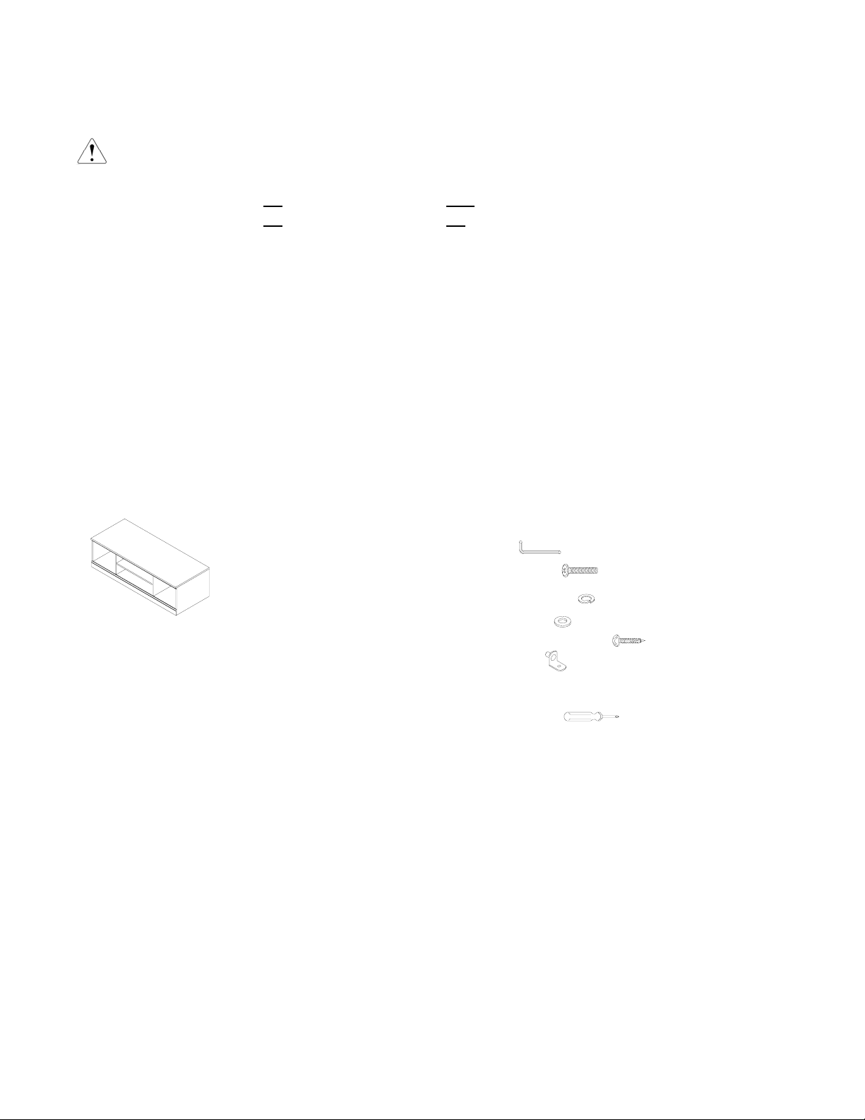
PARTS INCLUDED:
(A) Top Panel – 1pc
(B) Left Side Panel – 1pc
(C) Right Side Panel – 1pc
(D) Bottom Panel – 1pc
(E) Left Divider – 1pc
(F) Right Divider – 1pc
(G) Back Panel – 1pc
(H) Shelf – 1pc
HARDWARE ENCLOSED:
(I) Allen Key
(J) Bolt ¼“ x 25mm
(K) Spring Washer ¼“ – 12pcs
(L) Flat Washer ¼“
(M) Wood Screw 4 x 30mm
(N) Shelf Support
TOOLS REQUIRED:
Phillips Screwdriver
– 1pc
– 12pcs
– 12pcs
- 4pcs
(not included)
– 4pcs
Page 2
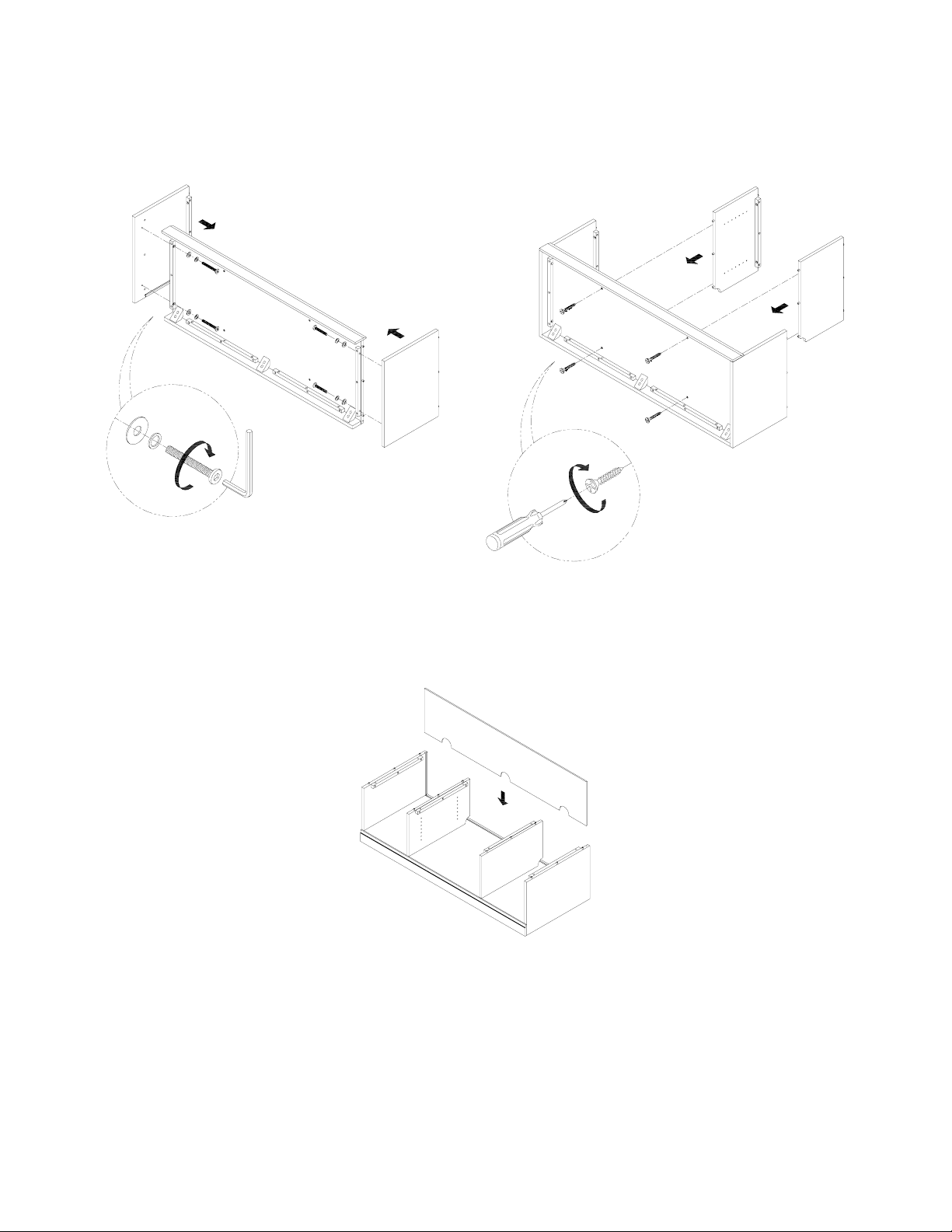
ASSEMBLY INSTRUCTIONS:
1. Connect the Left Side Panel (B) and Right Side Panel (C) to the Bottom Panel (D) by using (4) Flat Washer
(L), Spring Washer (K) and Bolt (J), securing with the Allen Key (I). (Fig.1)
2. Align and attach the Left Divider (E) and Right Divider (F) with the p re-drilled holes on the Bottom Panel,
securing by (4) Wood Screw (M) using a Philips Head Screwdriver. NOTE: the pre-drilled h oles of the
Dividers (E&F) must face each other. Please take care to properly orient these panels. (Fig. 2)
E.
B.
D.
F.
L.
K.
J.
C.
M.
I.
(Fig. 1)
3. Slide the Back Panel (G) into the slots of the assembled piece with the cord cut-outs positioned down.
(Fig. 3)
G.
(Fig. 2)
(Fig. 3)
Page 3
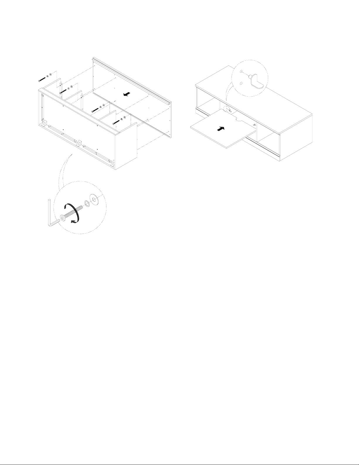
4. Align and place the Top Panel (A) on the assembled piece. Use (8) Flat Washer (L), Spring Washer (K)
and Bolts (J) to fasten the Top Panel (A) on the assembled piece securing by Allen Key (I). (Fig. 4)
5. Insert the (4) Shelf Pins (N) on the pre-drilled holes on the Left/Right Dividers (E&F) Place the Shelf (H)
on the Shelf Pins. (Fig. 5)
6. Check the alignment and fasten all the bolts and wo od screws.
A.
N.
(Fig. 5)
H.
L.
K.
J.
I.
(Fig. 4)
CARE INSTRUCTIONS:
• Dust often using a clean, soft, dry lint-free cloth.
• Blot spills immediately, and wipe with a clean, damp, cloth.
• We do not recommend the use of chemical cleansers, abrasives, or furniture polish on our lacquered
finish.
• Do not sit or stand on the top of the unit.
Thank you for your purchase.
stores | catalog | www.potterybarnkids.com
USA 1.800.290.8181
 Loading...