

Page 1
pottery barn kids
CAMERON CRAFT TABLE HUTCH
PRE-ASSEMBLY:
• Read all instructions before beginning assembly. The illustrations provided allow for easier assembly when
used in conjunction with the asse mbly instruction s.
• For your safety and ea se, assembly by two adults is recommended.
• Remove all parts and hardware from the box and lay out on a clean, carpeted, or scratch-free work surface.
Use care as some parts or hardw a re may ha ve sh arp poin ts or edge s.
• Do not dispose of any contents until assembly is completed to avoid accidentally discarding small parts or
hardware.
• Use the parts and hardware lists to identify and separate each of the pieces included.
• Note: Do not fully tighten all bolts until all parts are in place. Failure to follow these instructions may cause
the bolts to misalign during assembly.
• The use of power tools for assembly is not recommended. Power tools can damage hardware or split wood.
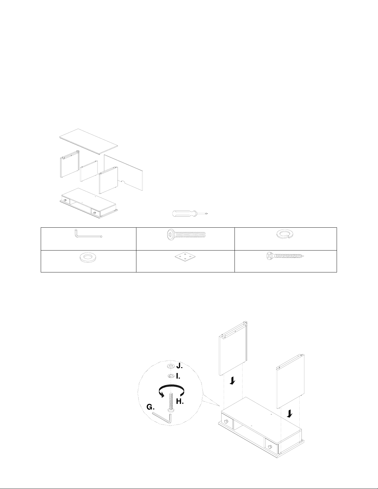
A.
(A) Top Panel – 1pc
(B) Bottom Unit – 1pc
PARTS INCLUDED:
C.
B.
F.
D.
E.
(C) Left Side Panel – 1pc
(D) Right Side Panel – 1pc
(E) Back Panel – 1pc
(F) Center Divider – 1pc
TOOLS REQUIRED:
Philips Screwdriver (Not included)
HARDWARE INCLUDED:
(G) Allen Key – 1pc
(J) Flat Washer – 8pcs
(H) Allen Bolt 1/4” x 28mm – 8pcs
(I) Spring Washer – 8pcs
(K) Square Bracket – 2pc s
(L) Wood Screw 3 x 12mm – 8pcs
ASSEMBLY INSTRUCTIONS:
1. Align and connect the wooden dowels on Left/Right Side Panels (C&D) to the pre-drilled holes on each
end of the Bottom Unit (B). Slide a Spring Wa sher (I), Fla t Wa sher (J) on to an Allen Bolt (H). Insert the
Allen Bolt from bottom of the Bottom Unit (B) into the pre-drilled holes located on bottom of the Left/Right
Side Panels, using the Allen Key (G). Repeat with another (3) Allen Bolts. (Fig. 1)
Fig. 1
C.
D.
B.
Page 1/3
Page 2
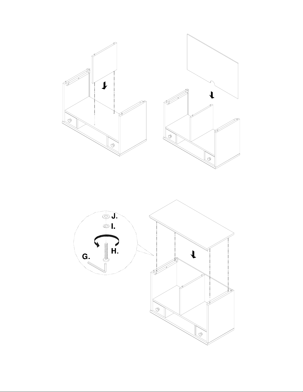
2. Align the wooden dowels on the Center Divider (F) to the pre-drilled holes on the assembled piece, (Fig
2). Slide the Back Panel (E) into the slots on the Left/Right Side Panels (Fig. 3).
Fig. 2 Fig. 3
3. Place the Top Panel (A) on the assembled piece. Slide a Spring Washer (I), Flat Washer (J) onto an Allen
Bolt (H) and insert the Allen Bolt from the wooden cleat on the Left/Right Side Panels into the Top Panel
(A) securing with the Allen Key (G). Repeat with the remaining (3) Allen Bolts.
Fig. 4
F.
Page 2/3
E.
A.
Page 3

4. When connecting to the Cameron Craft Table (sold separately), place the hutch on the table and secure
with (2) Square Mending Plates (K) and (8) Wood Screws.
L.
CARE INSTRUCTIONS:
• Dust often using a clean, soft, dry lint-free cloth.
• Blot spills imme diately, and wi p e wit h a c lean, damp, cloth.
• We do not recommend the use of chemical cleansers, abrasives, or furniture polish on our lacquered
finish.
Thank you for your purchase.
stores | catalog | www.potterybarnkids.com
USA 1.800.290.8181
Page 3/3
 Loading...