

Page 1

FJ500M User Guide
Positioning Universal Inc.
Positioning Universal, Inc. - Confidential & Proprietary
Version 1.0
Page 2

Model: FJ500M
2
Positioning Universal, Inc. - Confidential & Proprietary
Page 3

3
Document Revisions
Date
Version
Number
Document Changes
2019.5.11
1.0
First Release
Model: FJ500M
Positioning Universal, Inc. - Confidential & Proprietary
Page 4

Model: FJ500M
4
Regulatory Notice
Federal Communications Commission (FCC) and Industry
Canada (IC) Notice
Electronic devices, including computers and wireless modems, generate RF energy incidental to their
intended function and are therefore subject to FCC rules and regulations.
This equipment has been tested to, and found to be within the acceptable limits for a Class B digital
device, pursuant to Part 15 of the FCC Rules and Industry Canada ICES-003. These limits are
designed to provide reasonable protection against harmful interference when the equipment is
operated in a residential environment.
This equipment generates radio frequency energy and is designed for use in accordance with the
manufacturer’s user manual. However, there is no guarantee that interference will not occur in any
particular installation. If this equipment causes harmful interference to radio or television reception,
which can be determined by turning the equipment off and on, you are encouraged to try to correct the
interference by one or more of the following measures.
• Reorient or relocate the receiving antenna.
• Increase the separation between the equipment and the receiver.
• Consult the dealer or an experienced technician for help.
Connect the equipment into an outlet on a circuit different from that to which the receiver is connected
This device complies with Part 15 of the Federal Communications Commissions (FCC) Rules and with
Industry Canada (ICES-003). Operation is subject to the following two conditions:
• This device may not cause harmful interference.
• This device must accept any interference received, including interference that may cause
undesired operation.
Caution: Changes or modifications not expressly approved by the party responsible for compliance
could void the user‘s authority to operate the equipment.
RF Exposure Information
Positioning Universal, Inc. - Confidential & Proprietary
Page 5

Model: FJ500M
5
This device complies with FCC radiation exposure limits set forth for an uncontrolled environment. In
order to avoid the possibility of exceeding the FCC radio frequency exposure limits, human proximity to
the antenna shall not be less than 20cm (8 inches) during normal operation.
Le présent appareil est conforme aux CNR Innovation, Sciences et Développement économique
Canada applicables aux appareils radio exempts de licence. L'exploitation est autorisée aux deux
conditions suivantes:
(1) l'appareil ne doit pas produire de brouillage, et
(2) l'utilisateur de l'appareil doit accepter tout brouillage radioélectrique subi, même si le brouillage est
susceptible d'en
Innovation, Science and Economic Development Canada ICES-003 Compliance Label:
CAN ICES-3 (B)/NMB-3(B)
This Class B digital apparatus complies with Canadian ICES-003.
Cet appareil numérique de la classe B est conforme à la norme NMB-003 du
Canada.ISED Radiation Exposure Statement
This device complies with RSS-102 radiation exposure limits set forth for an uncontrolled environment.
In order to avoid the possibility of exceeding the ISED radio frequency exposure limits, human
proximity to the antenna shall not be less than 20cm (8 inches) during normal operation.
Cet appareil est conforme aux limites d'exposition aux rayonnements de la CNR-102 définies pour un
environnement non contrôlé. Afin d'éviter la possibilité de dépasser les limites d'exposition aux
fréquences radio de la CNR-102, la proximité humaine à l'antenne ne doit pas être inférieure à 20 cm
(8 pouces) pendant le fonctionnement normal.
Positioning Universal, Inc. - Confidential & Proprietary
Page 6

Model: FJ500M
6
Table of Contents
1 Introduction 8
2 Hardware 9
2.1 Physical and Electrical Specifications 9
3 Programming and Configuration Summary 10
3.1 DMAN Server 10
3.2 Applications 10
3.3 Settings Files 10
4 Tracking Behavior Summary 12
4.1 Power State Reporting 12
4.2 Absolute G detection 12
4.3 Moving State 12
4.4 Stopped State 12
4.5 Sleeping State 12
4.6 Heartbeat Reporting 13
4.7 Driver Behavior 13
4.8 AGPS 13
5 Detailed State Behavior 13
5.1 State Transitions 13
6 Detailed Moving Interval Reporting Logic 15
6.1 Moving Interval Locations 15
6.2 Moving Minor Locations 15
7 Detailed Reset Logic 17
7.1 Device Reboot 17
Periodic Reboot 17
Watchdog Reboot 17
Update Reboot 17
7.2 Comm Module Reset 17
Positioning Universal, Inc. - Confidential & Proprietary
Page 7

Model: FJ500M
7
No ACK Reset 18
No AT Command Reset 18
Command Based Reset 18
7.3 GPS Module Reset 18
No Location Message Reset 18
Command Based Reset 18
8 Message Resend Logic 19
9 Flash Storage Logic 20
10 Pinning, GPS Quality Filter, and AGPS 21
10.1 Pinning 21
10.2 Filter Parameters 21
10.3 Adding Events In Poor Coverage 21
10.4 AGPS 22
Positioning Universal, Inc. - Confidential & Proprietary
Page 8

Model: FJ500M
8
1 Introduction
The FJ500M is a remote asset tracking device that uses a GPS satellite receiver to determine
location information and an LTE transceiver to communicate information to and from a land
based server. It is designed to facilitate a broad array of asset tracking and telematics
services
This document outlines the operation and configuration of the FJ500M product line using
the supplied tracking application.
Integration of the FJ500M to a listening/parsing server and more details regarding
hardware use, configuration, and troubleshooting are contained in the FJ500M Integration
Guide.
Positioning Universal, Inc. - Confidential & Proprietary
Page 9
Model: FJ500M
9
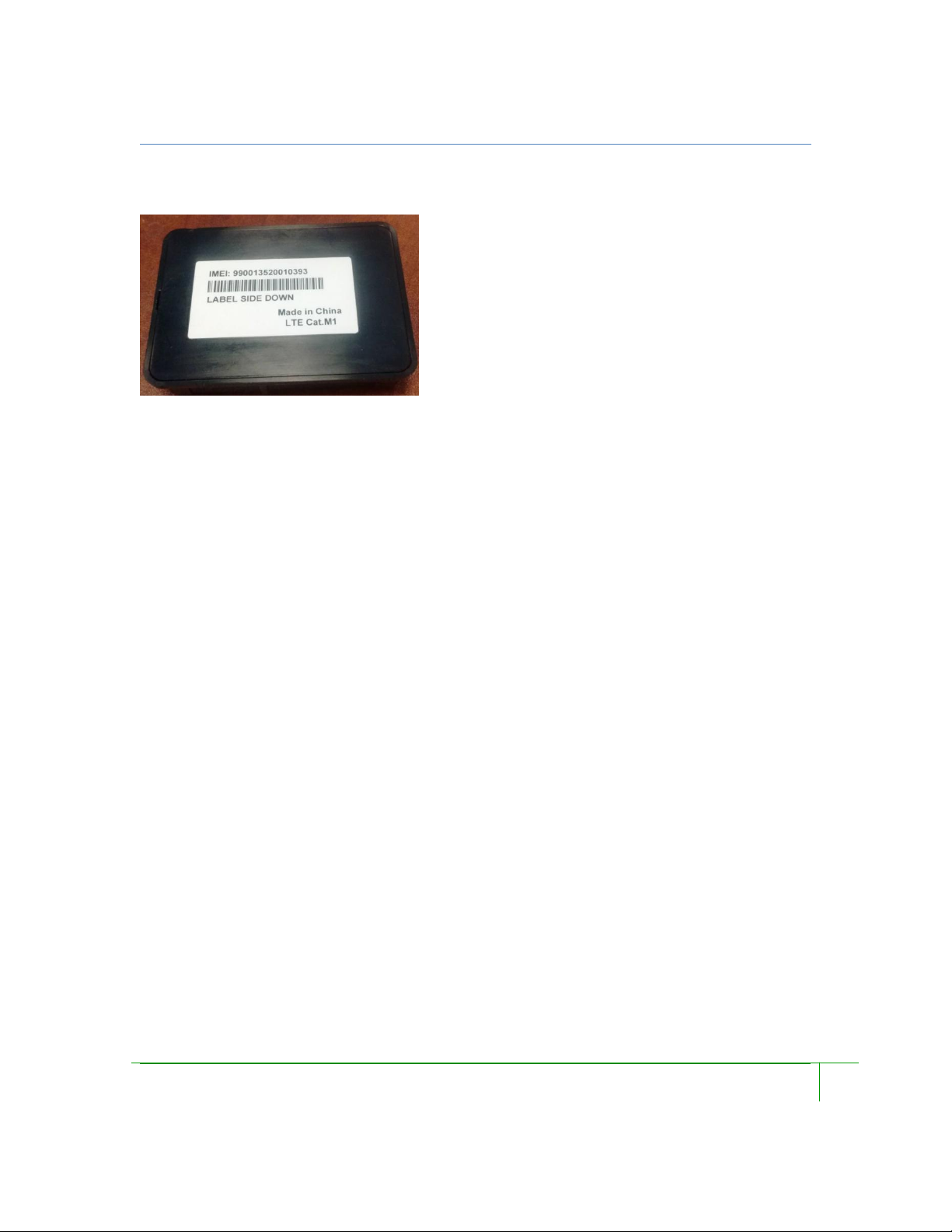
2 Hardware
2.1 Physical and Electrical Specifications
FCC Equipment Authorization ID: 2AHRH-FJ500M
Industry of Canada Certification Number: 24008-FJ500M
Dimensions: 88mm * 65mm * 20mm
Weight: 2 oz
Input Voltage: Battery (AAA) included
Power consumption:
- Active mode: 150mA@12VDC
- Low power mode: 15mA @ 12VDC
- Sleep mode: 6mA@ 12VDC
Operating temperature: -30℃ to 75℃
Storage temperature: -40℃ to 85℃
Positioning Universal, Inc. - Confidential & Proprietary
Page 10

Model: FJ500M
10
3 Programming and Configuration Summary
3.1 DMAN Server
3.2 Applications
3.3 Settings Files
FCC Equipment Authorization ID: 2AHRH-FJ500M
Industry of Canada Certification Number: 24008-FJ500M
FJ500M is programmed and configured either via the serial UART connection or via an
Over the Air (OTA) process on the cellular data network.
A Device Manager Server on the Positioning Universal infrastructure automatically
updates Applications and Settings files for groups of devices. When an update of the
application or new settings are released, they are loaded into the DMAN server and
assigned to the Groups of devices that are to receive the update. The DMAN server
automatically updates devices to the latest assigned versions. In normal operation,
devices “check in” to the DMAN server regularly to report their health, and to check
whether they are due to get updates.
The application provides standard tracking functionality to the FJ500M. The specific
operation and variations in behavior are provided via parameters included in a Settings
file. These parameter values may vary depending on the nature of the specific tracking
application that the device is employed in.
The Tracking Application is software developed to run on the FJ500M device family and
provide functions that are typically used in vehicle and asset tracking. Updates to the
application are provided by Positioning Universal to provide improvements, corrections,
and add new functionality when it is ready for release.
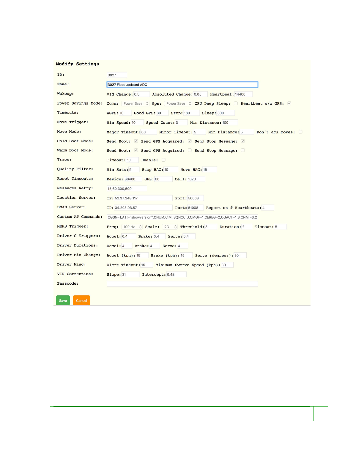
The parameters used by the application to control tracking and other functions are
contained in a settings file on the DMAN server and loaded to devices over the air. A
simple interface allows users to specify the values of relevant parameters for devices or
groups of devices. Below is an example of the settings file creation interface.
Please see the DMAN User Guide for details on how to create Settings Files.
Positioning Universal, Inc. - Confidential & Proprietary
Page 11
Model: FJ500M
11
FCC Equipment Authorization ID: 2AHRH-FJ500M
Industry of Canada Certification Number: 24008-FJ500M
Positioning Universal, Inc. - Confidential & Proprietary
Page 12

Model: FJ500M
12
4 Tracking Behavior Summary
4.1 Power State Reporting
4.2 Absolute G detection
4.3 Moving State
4.4 Stopped State
4.5 Sleeping State
FCC Equipment Authorization ID: 2AHRH-FJ500M
Industry of Canada Certification Number: 24008-FJ500M
FJ500M applications address the needs of typical vehicle and asset tracking. Variations in
functional behavior for specific applications is controlled via parameters in the settings
file.
The FJ500M can be configured to report power up and rebooting behavior in a variety of
ways depending on what is desired. Cold Boot, Warm Boot, and first GPS Acquisition
are reported if so configured following Power Up events, power cycling, commanded
reboots, and configured periodic reboots. In addition, there is an option to report a Stop
event following a reboot of a non-moving device to address some customer needs to
ensure that the corner case of a reboot occurring at the end of a trip doesn’t result in an
error in trip or idle reporting by the server.
Absolute G is an algorithm that detects low frequency changes in the resultant vector of
the acceleration reported by a MEMs accelerometer. This permits the device to detect
things like vehicle acceleration without a GPS fix. Higher frequency activity like normal
vibration, doors opening or closing, are filtered out. Exceeding the Absolute G threshold
specified in the Settings file will wake a device and put it in the Stopped state.
A device enters Moving state either due to detection of a hardwired Ignition signal, an
increase in the supply voltage, detection of movement by the GPS, or an “Absolute G”
detection. While in Moving state, the device reports periodically as configured. Both
primary Moving interval reports with full data, and “minor intervals” (with only latitude,
longitude, speed, and time) for data compression can be reported while in Moving state.
A device enters Stopped state when it wakes from Sleep, or when it exits Moving State
due to detection of a Stop event.
A device enters Sleeping state from Stopped state when all of vibration, GPS movement,
Positioning Universal, Inc. - Confidential & Proprietary
Page 13

Model: FJ500M
13
4.6 Heartbeat Reporting
4.7 Driver Behavior
4.8 AGPS
5 Detailed State Behavior
5.1 State Transitions
FCC Equipment Authorization ID: 2AHRH-FJ500M
Industry of Canada Certification Number: 24008-FJ500M
and primary voltage are quiescent for a sufficient duration. The qualifying duration of
quiescence, and the degree of sleep encountered, are controlled by parameters in the
Settings file.
The device reports a Heartbeat message at an interval specified regardless of state. If the
device is sleeping when the Heartbeat timer expires, it will wake up and generate the
Heartbeat message. Whether the device attempts a GPS fix for each Heartbeat message
can be specified.
Driver Behavior reporting is still in development and is not recommended for use at this
time.
Driver Behavior reporting generates alerts based on detection of g values that exceed
thresholds specified in the Settings file. The direction of the acceleration determines
whether the event represents Hard Acceleration, Hard Braking, or a Swerve.
Where the inbound server has the capability, Assisted GPS is employed if a GPS fix is
not available.
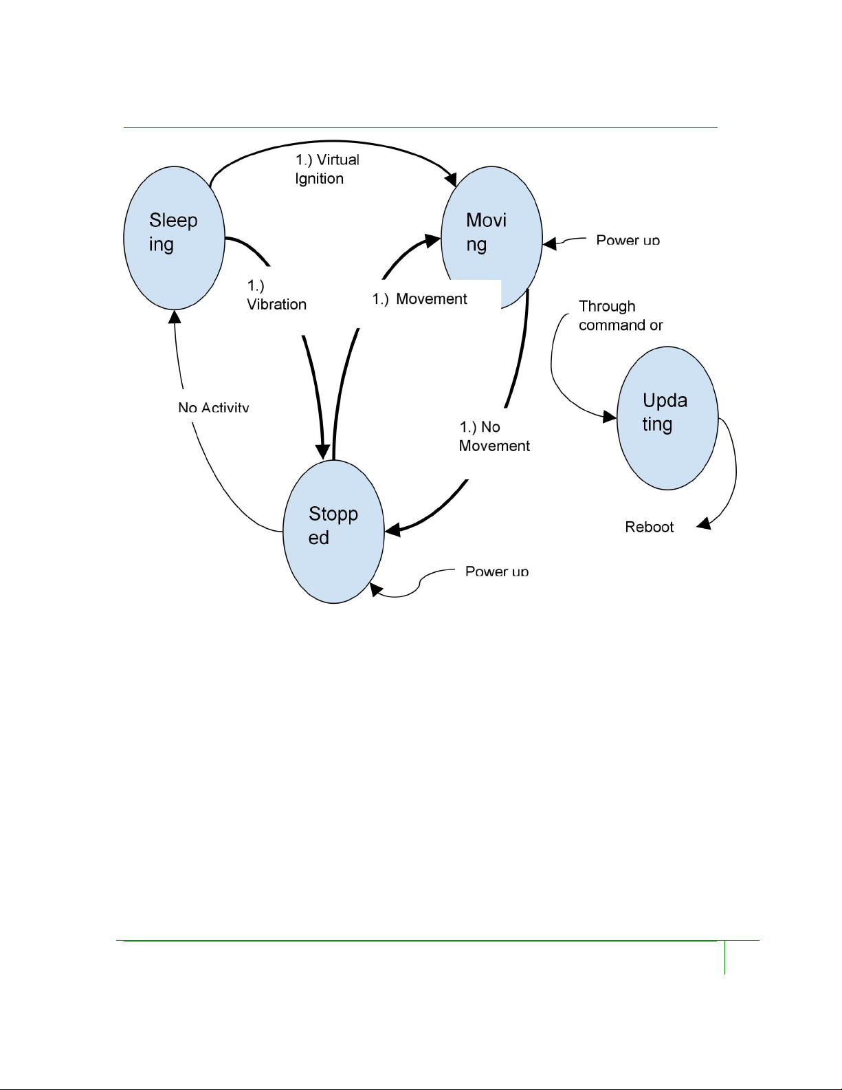
The following diagram details possible state transitions.
Positioning Universal, Inc. - Confidential & Proprietary
Page 14
Model: FJ500M
14
FCC Equipment Authorization ID: 2AHRH-FJ500M
Industry of Canada Certification Number: 24008-FJ500M
There are 3 main states in the software state machine: Moving, Stopped, Sleeping. There
is also an Updating state when the application or settings information on unit are being
updated. When in Updating state the device will ignore all normal behavior until unit is
updated at which time it is rebooted. The parameters and thresholds applied for state
transitions are primarily contained in the Settings File.
Positioning Universal, Inc. - Confidential & Proprietary
Page 15

Model: FJ500M
15
6 Detailed Moving Interval Reporting Logic
6.1 Moving Interval Locations
6.2 Moving Minor Locations
FCC Equipment Authorization ID: 2AHRH-FJ500M
Industry of Canada Certification Number: 24008-FJ500M
Move Interval Location messages are triggered by a time interval after the device has
entered the Moving state. Messages are sent on this time interval until the unit moves into
Stopped state.
If the unit enters a poor GPS area then the Move Location message is populated with the
last good latitude, longitude, satellites, horizontal accuracy. However, the VIN (main
power voltage), battery voltage, IO state, and RSSI are updated to current values.
Minor Move Location messages are size optimized messages which are appended to a
Location message representing offsets from main Location message.
If a device enters poor coverage, the minors associated up to the last good GPS location
are reported with next Move Major Message.
If a device receives an Ignition Off then all current minors are dumped with the Ignition
Off message.
However, if a device enters poor GPS coverage and then enters good GPS coverage
during a Move Major timeout, only the minors associated with the current good GPS
coverage are reported. So for example, if a device reports a Major Move then 10 seconds
later enters poor GPS coverage and then 20 seconds later enters good GPS coverage and
stays in good coverage until next Major Move report, only minors for the last 30 seconds
are reported as part of the Major Move.
Positioning Universal, Inc. - Confidential & Proprietary
Page 16

Model: FJ500M
16
FCC Equipment Authorization ID: 2AHRH-FJ500M
Industry of Canada Certification Number: 24008-FJ500M
If a unit moves more than 700 meters between minor locations then all minors are
dumped and the minor location logic is restarted.
Positioning Universal, Inc. - Confidential & Proprietary
Page 17

Model: FJ500M
17
7 Detailed Reset Logic
7.1 Device Reboot
7.2 Comm Module Reset
FCC Equipment Authorization ID: 2AHRH-FJ500M
Industry of Canada Certification Number: 24008-FJ500M
Cold Boot
Any time there is a physical power up event the device checks the status of the Cold Boot
Settings parameter and sends a Cold Boot message, a GPS Acquired message, and a Stop
message at the appropriate time if they have been specified.
Warm Boot
Any time there is a warm boot event the device checks the status of the Warm Boot
Settings parameter and sends a Warm Boot message, a GPS Acquired message, and a
Stop message at the appropriate time if they have been specified.
Periodic Reboot
Based on a parameter, the device can be set to perform a reboot periodically to address
any unhandled issues that may arise in the device.
Watchdog Reboot
If the microprocessor hasn’t been able to reach processor idle loop for 20 seconds then
the unit is automatically rebooted. This is to stop any endlessly running loop from
hanging the unit. This reboot is reported as a Cold Boot and is treated as a Cold Boot
from the point of view of Boot Settings.
Update Reboot
Every time the device has its application or settings file updated, the device is rebooted.
Also if the device times out during update it will reboot. This reboot appears on server as
a Cold Boot and is treated as a Cold Boot from the point of view of Boot Settings.
There are a number of conditions which trigger the comm module be reset.
Positioning Universal, Inc. - Confidential & Proprietary
Page 18

Model: FJ500M
18
7.3 GPS Module Reset
FCC Equipment Authorization ID: 2AHRH-FJ500M
Industry of Canada Certification Number: 24008-FJ500M
No ACK Reset
If a message has been sent requiring an ack then a timer is set. If no ack is received
before the timer then the module will be reset. This logic is intended to cause the comm
module to be reset if it is locked up but still reporting some kind of comm update.
No Comm Available Reset
If the module has not reported that it is available for comm within the time specified then
the module will be reset.
No AT Command Reset
If no AT response has been received from the Comm module for a given time after
sending an AT command, then the Comm module is reset.
Command Based Reset
If the device receives a “comm,reset” command through UDP or SMS or serial port, then
the module is reset.
No Location Message Reset
The GPS module is rebooted (physically powered off and then on) if no gps location is
received from it for a specified number of seconds. This will prevent the GPS module
being powered up and having sent a number of locations and then stopping. A typical
value for this parameter is 30 seconds.
Command Based Reset
If the device receives a “gps,reset” command through UDP or SMS or serial port, then
the module is reset.
Positioning Universal, Inc. - Confidential & Proprietary
Page 19

Model: FJ500M
19
8 Message Resend Logic
FCC Equipment Authorization ID: 2AHRH-FJ500M
Industry of Canada Certification Number: 24008-FJ500M
A send fails if an ack is not received within the specified retry interval.
The interval of resend is specified through a parameter array in seconds, e.g. [15, 60, 300,
600]. In this case, a send fails if no ack received within 15 seconds on the first message
send, 60 seconds on the second and so on.
Each time a message is retried the backoff index is incremented by 1 so in example above
after sending a message and not receiving a response the next message will be 15 seconds.
When the last value of array is reached, it is repeated until a server ack is received. An
ack reverts the logic to original state.
Positioning Universal, Inc. - Confidential & Proprietary
Page 20

Model: FJ500M
20
9 Flash Storage Logic
FCC Equipment Authorization ID: 2AHRH-FJ500M
Industry of Canada Certification Number: 24008-FJ500M
Pending location messages are stored in a small RAM based queue.
Once more than 3 messages are queued in RAM then all queued locations and all
subsequent locations are stored in flash memory until there are no outstanding locations
at which point it reverts to a RAM queue. If the device enters sleep mode then all
messages in RAM are stored in flash.
Controlled reboots are caused by the reboot command, and periodic timeouts and result in
the saving of RAM queue to flash. All other reboots can’t be controlled and the up to 3
messages in the RAM queue will be lost.
It is desirable to store as few locations to flash as possible since flash on device can wear
out after 10K erase cycles so the RAM queue greatly reduces number of unnecessary
write cycles.
The FJ500M can store around 2150 messages in flash memory.
Positioning Universal, Inc. - Confidential & Proprietary
Page 21

Model: FJ500M
21
10 Pinning, GPS Quality Filter, and AGPS
10.1 Pinning
10.2 Filter Parameters
● has more than or equal to the minimum number of satellites
● has at least the minimum Horizontal Accuracy (HAC) estimate. Note that the
10.3 Adding Events In Poor Coverage
FCC Equipment Authorization ID: 2AHRH-FJ500M
Industry of Canada Certification Number: 24008-FJ500M
The Quality Filter is needed to prevent poor quality gps data from triggering erroneous
events. Only good quality locations which meet the quality filter are used in move
locations. The GPS module reports locations on a 5 HZ interval.
Typically, the location reported by a GPS device is an estimate of location based on the
calculations inside the GPS module. This estimate can vary over time, even for a
stationary vehicle because of the effects of the moving satellites and atmospheric and
local conditions. This can result in the module reporting a stationary object as moving
slowly. In addition, occasional interferences or satellite signal reflections can result in
errant location reporting.
GPS quality is used to filter out suspect information based on the number of satellites
whose signals are reaching the GPS module at any given time, in addition to estimates the
module makes of how accurate the fix might be. To reduce the risk of falsely reporting
that a stationary device is moving, the GPS module “pins” the device location to a fixed
point when the fix appears to be stable and not moving a significant distance.
A location will be considered good if it meets the following criteria:
minimum can vary based on Stopped or Moving state. A tighter HAC threshold is
typically used in Stopped state to reduce the incidence of “false” indication of
movement
If a location is below the quality threshold then it will not be used for event reporting.
Instead the last good location will be used for new events. This means that when a
vehicle enters an underground garage, it will appear to stop at the entrance to the garage
since the device probably hasn’t received any good locations after it entered.
Positioning Universal, Inc. - Confidential & Proprietary
Page 22

Model: FJ500M
22
10.4 AGPS
● The device has transitioned to Moving state
● The device doesn’t have a valid GPS fix
● The AGPS delay timer has expired (since transition to Moving state)
FCC Equipment Authorization ID: 2AHRH-FJ500M
Industry of Canada Certification Number: 24008-FJ500M
The device attempts to download GPS assist data from the DMAN server using current
cell tower information when the following conditions are met:
The transition to Moving state with an invalid GPS can only occur on Ignition On or
Virtual Ign On event. The device must enter Sleeping state before another Moving state
transition will cause another AGPS request.
Positioning Universal, Inc. - Confidential & Proprietary
 Loading...