

Page 1
PP2000 Series
2 Station Printer
User’s Guide
Rev. A
Page 2

Federal Communications Commission Radio Frequency
Interference Statement
This equipment has been tested and found to comply with the limits for a Class A digital
device, pursuant to Part 15 of the FCC Rules. These limits are designed to provide reasonable protection
against harmful interference when the equipment is operated in a commercial environment. This
equipment generates, uses, and can radiate radio frequency energy and, if not installed and used in
accordance with the instruction manual, may cause harmful interference to radio communications.
Operation of this equipment in a residential area is likely to cause harmful interference in which case
the user will be required to correct the interference at his own expense.
For compliance with Federal Noise Interference Standard, this equipment requires a shielded cable.
This statement will be applied only for the printers marketed in U.S.A.
CE manufacturer’s Declaration of Conformity
(EC Council Directive 89/336/EEC of 3 May 1989)
This product has been designed and manufactured in accordance with the International Standards
EN50081-1/01.92 and EN50082-1/01.92 following the provisions of the Electro Magnetic
Compatibility Directive of the European Communities as of May 1989
Warranty Limits
Warranty will terminate automatically when the machine is opened by any person other than
the authorized technicians. The user should consult his/her dealer for the problem happened. Warranty
voids if the user does not follow the instructions in application of this merchandise. The manufacturer is
by no means responsible for any damage or hazard caused by improper application.
About This Manual
This manual is aimed to assist the user to utilize the PP2000 series which is a series of POS
thermal printers delicately designed to work with either serial or parallel interface connection. This
manual covers both operational and technical aspects. This manual is revised to cover also the Epson
emulation commands and some frequently asked questions.
The manufacturer of the PP2000 series heartily apologizes to the user for reserving the right to
change or to modify this manual without notice due to the rapid and constant progress and improvement
on science and technology. The user may always obtain the most up to date information through our
web site: http://www.posiflex.com.tw .
© Copyright Mustek Corp. 1999
All rights are strictly reserved. No part of this documentation may be reproduced, stored in a
retrieval system, or transmitted in any form or by any means, electronic, mechanical, photocopying, or
otherwise, without the prior written consent of Mustek Corp. the publisher of this documentation.
Page 3

Table of Contents
PRODUCT BRIEFING . . . . . . . . . . . . . . . . . . . . . . 1 -- 1
MAIN PARTS ON THE EXTERIOR . . . . . . 2 -- 1
OUTPUT AREAS . . . . . . . . . . . . . . . . . . . . . . . . . . . . . . 2 -- 1
CONTROL PANEL . . . . . . . . . . . . . . . . . . . . . . . . . . . . 2 -- 1
INPUT / OUTPUT CONNECTOR . . . . . . . . . . . . . . . .2 -- 2
INSTALLATION . . . . . . . . . . . . . . . . . . . . . . . . . . . . . 3 -- 1
CHECK CONTENTS . . . . . . . . . . . . . . . . . . . . . . . . . . . 3 -- 1
OPEN TOP COVER . . . . . . . . . . . . . . . . . . . . . . . . . . . . 3 -- 1
STORE STAMP INSTALLATION . . . . . . . . . . . . . . . 3 -- 2
RIBBON INSTALLATION / REPLACEMENT . . . . . 3 -- 3
CASH DRAWER CONNECTION . . . . . . . . . . . . . . . . 3 -- 4
CONNECT TO HOST COMPUTER . . . . . . . . . . . . . . 3 -- 4
POWER CONNECTION . . . . . . . . . . . . . . . . . . . . . . . . 3 -- 4
POWER ON . . . . . . . . . . . . . . . . . . . . . . . . . . . . . . . . . . 3 -- 5
PAPER ROLLS INSTALLATION . . . . . . . . . . . . . . . . 3 -- 5
SELF TEST . . . . . . . . . . . . . . . . . . . . . . . . . . . . . . . . . . . 3 -- 6
REPLACE TOP COVER . . . . . . . . . . . . . . . . . . . . . . . . 3 -- 6
CLEAR BUFFER . . . . . . . . . . . . . . . . . . . . . . . . . . . . . . 3 -- 6
MAINTENANCE NOTICES . . . . . . . . . . . . . . . . 4 -- 1
SOFEWARE COMMANDS . . . . . . . . . . . . . . . . . 5 -- 1
SPECIFICATIONS . . . . . . . . . . . . . . . . . . . . . . . . . . . 6 -- 1
VALIDATION PRINTING . . . . . . . . . . . . . . . . . . . . . . 6 -- 1
PAPER ROLL . . . . . . . . . . . . . . . . . . . . . . . . . . . . . . . . . 6 -- 1
LED INDICATIONS . . . . . . . . . . . . . . . . . . . . . . . . . . . 6 -- 2
BUTTON FUNCTIONS . . . . . . . . . . . . . . . . . . . . . . . . . 6 -- 2
PRINTER GENERAL SPEC . . . . . . . . . . . . . . . . . . . . . 6 -- 3
PP2000 (E) User’s Manual
i
Page 4

STORE STAMP (OPTION) . . . . . . . . . . . . . . . . . . . . . . 6 -- 4
INTERNAL SWITCHES . . . . . . . . . . . . . . . . . . . . . . . . 6 -- 4
CASH DRAWER CONNECTOR . . . . . . . . . . . . . . . . . 6 -- 5
SERIAL INPUT CONNECTOR (STANDARD 9 PIN RS232
INTERFACE) . . . . . . . . . . . . . . . . . . . . . . . . . . . . . . . . . 6 -- 5
POWER INPUT CONNECTOR . . . . . . . . . . . . . . . . . . 6 -- 5
PARALLEL INPUT CONNECTOR (STANDARD 25 PIN
SPP INTERFACE) . . . . . . . . . . . . . . . . . . . . . . . . . . . . . 6 -- 5
DIMENSION AND WEIGHT . . . . . . . . . . . . . . . . . . . . 6 -- 5
ENVIRONMENT . . . . . . . . . . . . . . . . . . . . . . . . . . . . . . 6 -- 6
RELIABILITY . . . . . . . . . . . . . . . . . . . . . . . . . . . . . . . . 6 -- 6
POWER ADAPTOR PA-300 . . . . . . . . . . . . . . . . . . . . . 6 -- 6
REGULAR MAINTENANCE PROCEDURE . . .
. . . . . . . . . . . . . . . . . . . . . . . . . . . . . . . . . . . . . . . . . . . . . . . . . . . 7 -- 1
DAILY MAINTENANCE . . . . . . . . . . . . . . . . . . . . . . . 7 -- 1
PERIODIC MAINTENANCE . . . . . . . . . . . . . . . . . . . . 7 -- 2
BASIC TROUBLES SHOOTING . . . . . . . . . . 8 -- 1
NO OPERATION AFTER POWER ON . . . . . . . . . . . 8 -- 1
CAN NOT PRINT WITH A NORMAL POWER ON .8 -- 1
USE SELF TEST CAPABILITY IN CASE OF DOUBT . . . . .
. . . . . . . . . . . . . . . . . . . . . . . . . . . . . . . . . . . . . . . . . . . . . . 8 -- 1
PAPER JAMMED . . . . . . . . . . . . . . . . . . . . . . . . . . . . . .8 -- 2
ii
PP2000 (E) User’s Manual
Page 5

I. PRODUCT BRIEFING
This is a high speed 2 - station journal / receipt printer.
l A standard 2 station Journal / Receipt printer: The printing paper
width is 44.5mm. The printer can print both journal and receipt at the
same time or only journal or receipt alone.
l The ability for validation printing.
l The configuration of print head is a 9 Pin impact print head. The
maximum printing speed is about 3 lines / sec and 24 characters /
line. The paper feed speed by command of each journal and receipt is
about 30 lines / sec.
l There are 3 code pages including USA, Multilingual and Portuguese
for use.
l There are 16 sets of international character sets.
l There are two kinds of different interfaces including a 9 pin D
subminiature connector for serial interface and a 25 pin D
subminiature connector for parallel interface and the printer can
automatically detect which one is in use.
l High capacity of printing buffer max. 32 KB can receive data
speedily and store a large quantity of data.
l The ability of controlling two cash drawers.
l Built-in stand-by power to hold data for 1 hour from power off or
power failure so that the printing can be continued after power
resume. (This function can be disabled by jumper.)
l The ability of self-detection on errors like print head overheated.
l Clear LED status indication and easy operating buttons.
l External power supply or +24V DC power from the POS system.
l The PP2000 can be connected to a customer display and work under
pass through commands.
l The life of print head expands considerably
l The style of the model is exquisite and beautiful. The printer itself
takes very little space of the operation site and it is easy to use.
PP2000 (E) User’s Manual
1 - 1
Page 6

l Options include auto stamping ability of the store stamp on receipt
and auto cutting of the receipt.
l The ability of cutting paper in full or in part by software on receipt.
1 - 2
PP2000 (E) User’s Manual
Page 7
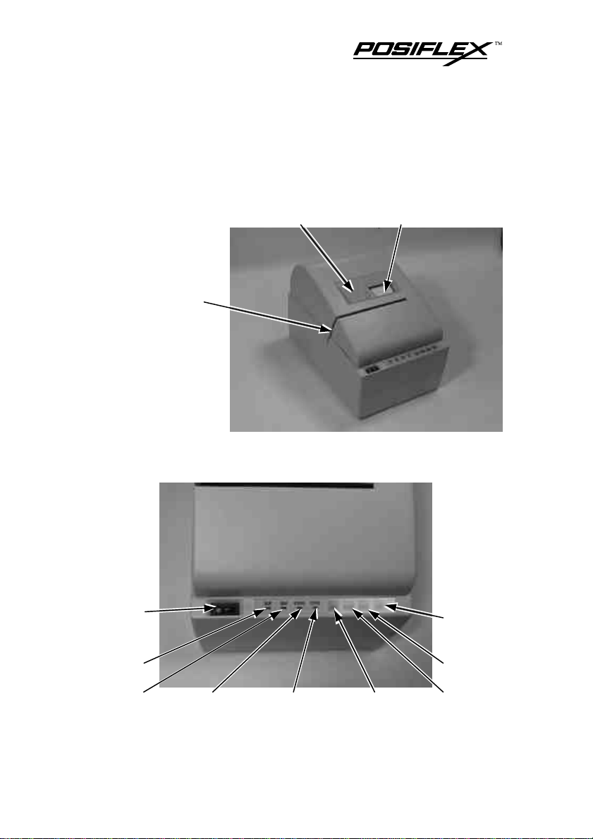
II. MAIN PARTS ON THE EXTERIOR
A. OUTPUT AREAS
Receipt exit slot Journal window
Validation printing
insert slot
B. CONTROL PANEL
Power
On/Off
switch
Power
LED
On line LED
PP2000 (E) User’s Manual
Receipt LED Journal LED On line switch
Manual
stamping
switch
Journal
switch
Receipt switch
2 - 1
Page 8
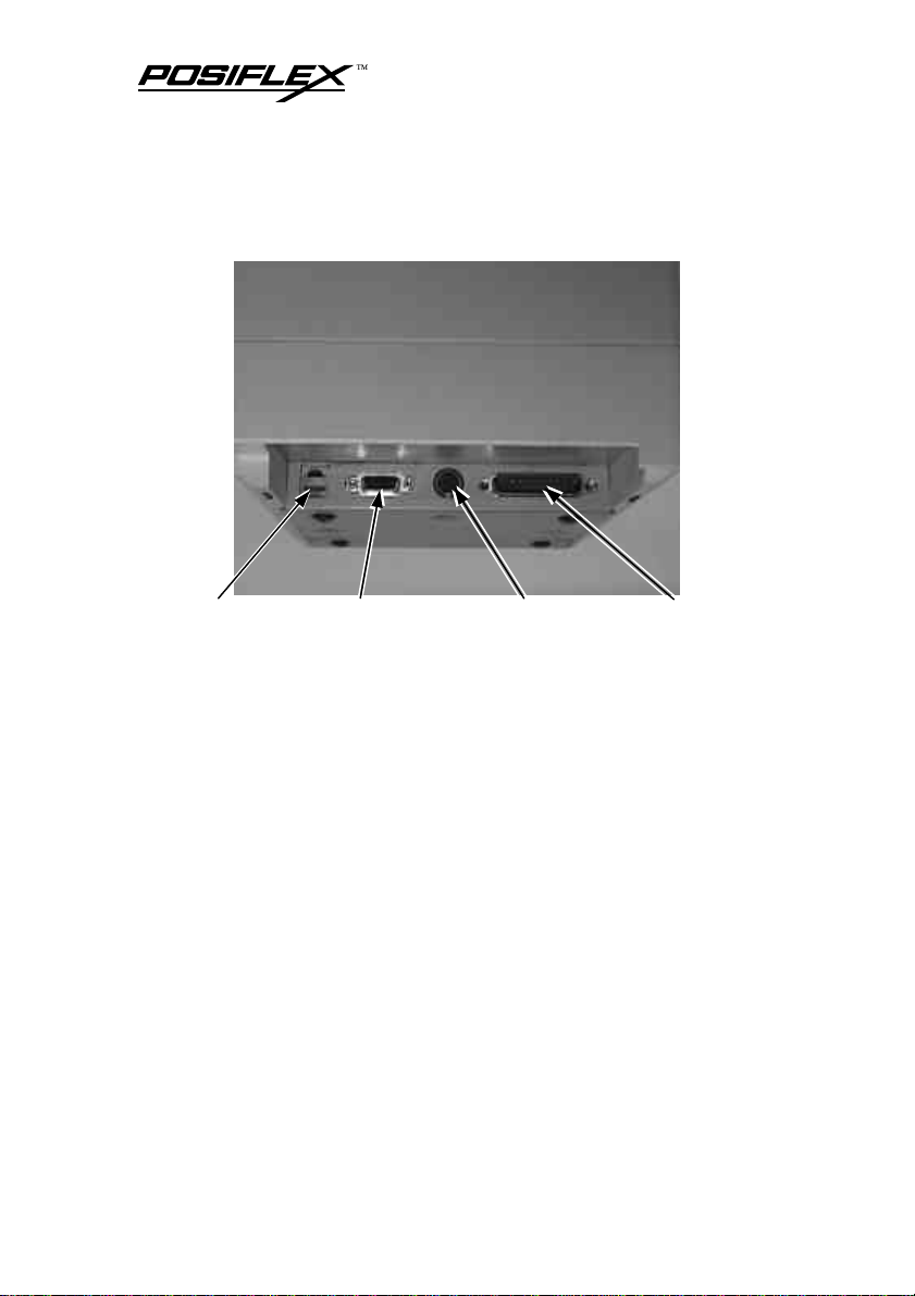
C. INPUT / OUTPUT CONNECTOR
Cash drawer
connector
2 - 2
Serial connector Power connector Parallel connector
PP2000 (E) User’s Manual
Page 9
III. INSTALLATION
A. CHECK CONTENTS
When you unpack carefully the carton that delivers PP2000 series
printer, you will find it contains several items as illustrated below.
ll PP2000 2 - station receipt / journal printer
ll Two rolls of paper roll sample
ll One set of ribbon
ll Power adaptor with power cord (option)
If there is any discrepancy or problem, contact your dealer
immediately. Be sure to save the packing materials in the event that
the printer may need to be shipped at some point in the future.
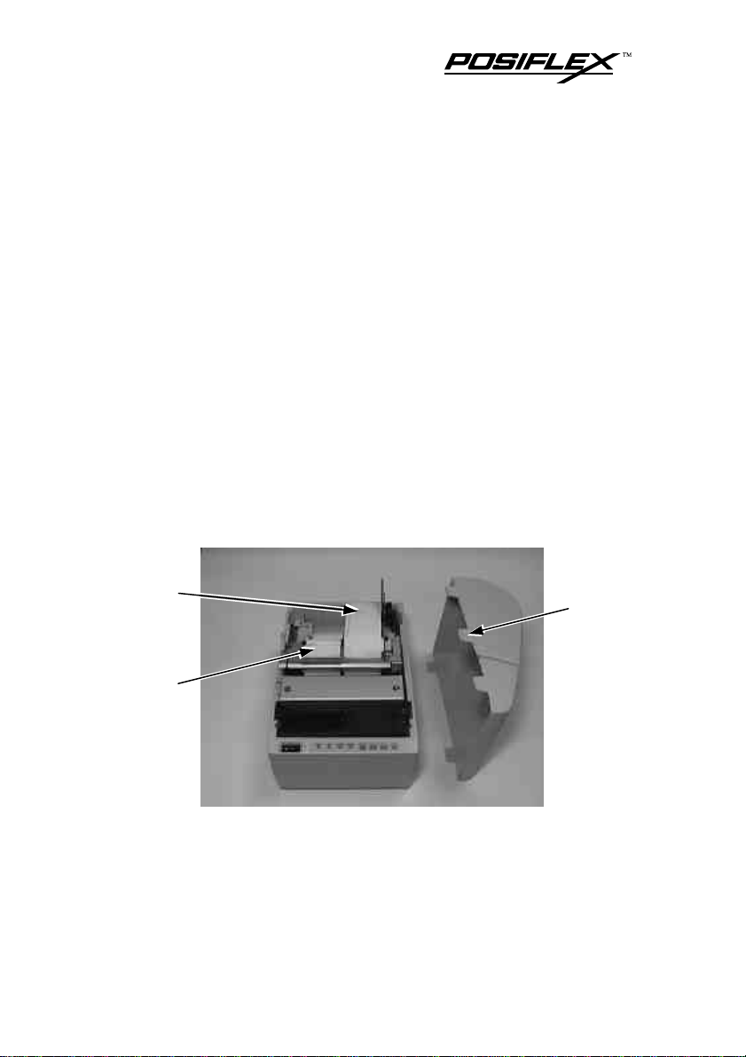
B. OPEN TOP COVER
Journal
Receipt
Please check the Power On / Off switch to be Off. Open top
cover by gently pressing the rear part of top cover inward and lift it up.,
The above figure illustrates the result.
PP2000 (E) User’s Manual
Hook
3 - 1
Page 10

C. STORE STAMP INSTALLATION
Print anvil
assembly
If your printer comes with stamp option, you can find a store
stamp case in the rear of the receipt part of print anvil assembly. You
may take it out gently by holding its handle with your fingers.
Top of
stamp
Print head
assembly
Assembled
sample
Holder Spring piece Store stamp Cushion
Disassemble the holder and the spring piece away from the stamp
case, then install the store stamp, which is engraved with store name or
logo, and cushion and reassemble the spring piece and holder onto the
stamp case as illustrated in the picture above. Please note the direction
3 - 2
PP2000 (E) User’s Manual
Store stamp
case
Page 11

of store stamp. When the printing ink of the stamp is not enough, you
can drip printing ink into the two holes in the rear of the stamp case.
D. RIBBON INSTALLATION / REPLACEMENT
Location of
Handle of
the ribbon
When replacing the ribbon, please take the handle at the center of
the old ribbon case and lift it up. Then the old ribbon can be taken out.
the ribbon
Knob of
the ribbon
When installing a new ribbon, please place the new ribbon to a
suitable position and align the axle hole under the ribbon case to the
driving axletree of the printer. Then push down the ribbon case. Now
PP2000 (E) User’s Manual
3 - 3
Page 12

turn the knob of the ribbon in the marked direction to tighten the ribbon
and to ensure proper operation of the ribbon and to avoid jamming.
E. CASH DRAWER CONNECTION
Using the Posiflex signal cable CCBLA-180 to control a Posiflex
cash drawer (CR3100 or CR3200). However, by using the Posiflex
signal split cable CCBLA-238, PP2000 series can control two Posiflex
cash drawers (CR3100 or CR3200). (CCBLA-180 is a standard
accessory with the Posiflex cash drawer CR3100 or CR3200.)
F. CONNECT TO HOST COMPUTER
The interface from PP2000 to host computer utilizes auto –
detection between serial and parallel. To avoid improper operation,
when one communication interface is in use, the input connector of the
other interface should never be connected with any cable. All the
external connectors are in the recessed area at the rear bottom. The 9 pin
D sub Female connector supports the RS232 series interface and the 25
pin D sub Male connector supports the parallel interface. The protocol
used in serial connection is defaulted: 9,600 bps, parity none, 8 data bits,
1 stop bit. The baud rate is adjustable from 2,400 to 19,200 bps.
G. POWER CONNECTION
If used with Posiflex PST POS system, PP2000 can use DC power
and the power cable from the POS system. If not, user must purchase
PP2000 standard power adaptor. Pull the outer sleeve of the 3 pin plug
of the power adaptor or power cord from the POS system backward to
release the internal latch. Then insert the plug to the power connector
and be sure to hear the click to obtain a firm contact. (Before extraction
of this power cable, be sure to pull the outer sleeve of the plug backward
too. Failure to do this could damage the power plug.) And then connect
the power cord of the power adaptor to the wall outlet or turn on the
POS system. Make sure that the type of power cord and the voltage
requirement of the power adaptor meet the local power conditions. Now
the printer is ready for power on.
3 - 4
PP2000 (E) User’s Manual
Page 13

H. POWER ON
journal
Turn on the On/Off switch at the left to the control panel, there
will be a short buzzing sound and it indicates a normal power on.
I. PAPER ROLLS INSTALLATION
Direction of rolling
Pick up
reel of
Journal
lever
Roll of
journal
Roll of
receipt
Insert slot of journal Insert slot of receipt
1. Please refer to the picture above: Put the receipt roll into the left
paper roll compartment and the journal roll into the right. Please note
that the direction of paper roll is to be pulled up under the roll.
2. Push and hold down the receipt lever and insert the front end of
receipt into the insert slot of receipt. When the front end of receipt is
shown from the front end of the insert slot, release the receipt lever.
3. Push and hold down the journal lever and insert the front end of
journal into the insert slot of journal. When the front end of journal is
shown from the front end of the insert slot, feed the paper enough to
be fixed to the pick up reel of journal and release the journal lever.
Insert the front end of journal into the center slot of the reel and turn
the reel in the indicated direction to fix the journal.
Receipt
lever
PP2000 (E) User’s Manual
3 - 5
Page 14

4. To give an idea about the positioning matter of the receipt, the print
center is 33.3 mm behind the auto-cut position, whilst the stamp
center is 40.0 mm behind the print center.
J. SELF TEST
Please power off the printer for at least three seconds and then
press and hold the receipt button while turning the on / off switch on. A
slip of self test result is printed on both receipt and journal side. Any
signal of the receipt button after the printing of self test result will cause
paper feed of receipt.
K. REPLACE TOP COVER
If there is any difficulty in applying all the five hooks on top cover
into the bottom base of the printer, always align the left three hooks first
and then press down the top cover to the base. In this way, the top cover
will not come in conflict with the receipt lever
L. CLEAR BUFFER
The PP2000E series provides a data preservation function during
power off. This function helps the user to go on printing after an
unexpected power failure. However there can be occasions that the user
wants to restart the printer without printing the unwanted data received
before the printer is turned off. To have the data input buffer cleared, the
user may turn off the printer then press and hold both on line and journal
switches during turning on the printer again.
3 - 6
PP2000 (E) User’s Manual
Page 15

IV. MAINTENANCE NOTICES
l The printer should be put at a well ventilated site and avoid direct
sunshine, also avoid high temperature, high humidity, high
magnetic field. The site should also be free from lots of metal chips
and dust.
l Never place any vessel for water alcohol beverages or any kind of
fluid over the printer. Otherwise it may get turned over and damage
the component inside.
l Use only alcohol or neutral detergent for cleaning of the exterior,
please never use organic solvent like benzene or thinner.
l Maintenance guide:
Ribbon :
Replace for a new one every three months or twenty thousand
pieces of receipt/journal printing. Please do not pour ink into
the ribbon or it is easy to damage the print head.
Print head:
Replace for a new one every seventy thousand pieces of
receipt/journal printing.
Store stamp:
Add ink into store stamp once every three months or twenty
thousand pieces of receipt/journal printed. To avoid illegible
stamping, please replace new store stamp once every twelve
months or eighty thousand pieces of receipt/journal printing.
Auto cutter:
Clean any paper cutting residue and dust in the auto cutting
mechanism regularly to avoid sensor malfunction and paper
jam.
² Use of any ribbon other than the standard supply from the
manufacturer (ERC-32) or refilling of any ink to the ribbon
may cause damage like broken pin in the print head and/or
other consequences. Such damage and consequences are
responsibility of the user and are out of the warranty of the
manufacturer.
PP2000 (E) User’s Manual
4 - 1
Page 16

Page 17

V. SOFTWARE COMMANDS
The commands supported by the PP2000 Printer are listed below.
For detail description of the below listed commands, please visit our
web site http://www.posiflex.com.tw for detail descriptions of each
command.
NAME HEX FUNCTION
LF 0A Print and line feed
CR 0D Print and carriage return
ESC SP 1B 20 Set right side character spacing
ESC ! 1B 21 Select print mode(s)
ESC $ 1B 24 Set absolute print position
ESC % 1B 25 Select/cancel user-defined characters set
ESC & 1B 26 Define user-defined characters
ESC * 1B 2A Select bit-image mode
ESC - 1B 2D Turn underline mode on/off
ESC < 1B 3C Return home
ESC = 1B 3D Select peripheral device
ESC ? 1B 3F Cancel user-defined characters
ESC @ 1B 40 Initialize printer
ESC E 1B 45 Turn emphasized mode on/off
ESC G 1B 47 Turn double-strike mode on/off
ESC R 1B 52 Select an international character set
ESC U 1B 55 Turn unidirectional printing on/off
ESC \ 1B 5C Set relative print position
ESC c 0 1B 63 0 Select paper type for printing
ESC d 1B 64 Print and feed n lines
ESC i 1B 69 Full cut
ESC m 1B 6D Partial cut
5 - 1
PP2000 (E) User’s Manual
Page 18

Software commands continued.
NAME HEX FUNCTION
ESC o 1B 6F Stamp
ESC p 1B 70 Generate pulse
ESC t 1B 74 Select character code table
ESC u 1B 75 Transmit peripheral device status
ESC v 1B 76 Transmit paper sensor status
ESC z 1B 7A
GS * 1D 2A Define download bit image
GS / 1D 2F Print download bit image
Turn parallel printing mode on for receipt and
journal
PP2000 (E) User’s Manual
5 - 2
Page 19

VI. SPECIFICATIONS
A. VALIDATION PRINTING
84.5
Print area
Sensor
Unit: mm
Note: Do not scale
Paper width: 140 mm or above
Paper height: 65 mm or above
Paper thickness: 0.07 ~ 0.14 mm
Validation print: One line
Number of characters: 55
Print area and sensor position: As illustrated in drawing above
10
8
22
2
B. PAPER ROLL
Paper type: High quality paper
Paper roll width: 44.5 +/- 0.5 mm
Paper roll max. O. D.: 83 mm
Paper thickness: 0.06 ~ 0.09 mm
6 - 1
PP2000 (E) User’s Manual
Page 20

C. LED INDICATIONS
Power LED: Green: Printer power is working
On line LED: Green: Printer is at on line state. The printer takes
command from the host system at this state and
takes no command from the buttons.
Receipt LED: Red: Receipt paper is out, or malfunction with receipt
print.
Journal LED: Red: Journal paper is out or malfunction with journal
print.
D. BUTTON FUNCTIONS
On line button: Switches the printer between on line and off line states.
The data in the buffer keep printing out.
Receipt button: Feeds receipt forward one line by each press under off
line state.
Journal button: Feeds journal forward one line by each press under off
line state. Can be used to clear buffer if the printer
switched on while both this button and on line button are
pressed.
Stamp button: Execute one stamp operation by each press under off
line state. (Applicable with stamp option only)
PP2000 (E) User’s Manual
6 - 2
Page 21

E. PRINTER GENERAL SPEC
ITEM SPECIFICATION
Functions Receipt, journal and validation printing
Printing Method
Printing Speed About 3 lines/sec., bi-directional
Printing Capacity
Paper Feed Receipt and journal by separate friction feed
Max.
Paper Feed Speed
Built in Characters 3 code pages with 16 international character sets
Data Buffer 32KB max.
Paper Type
Inked Ribbon EPSON ERC-32(P) purple
Receipt Auto Cut
Pattern
Interface Auto detect between RS232 and Centronics
Sensor Print head over heat protection
Control over
Cash Drawers
Power Used DC 24V
9pin dot matrix impact; synchronized or
separate printing of receipt and/or journal
Receipt: 24 characters/line
Journal: 24 characters/line
Validation: 55 characters in one line
About 30 lines/sec.
Receipt: paper roll (44.5 mm wide x 83 mm
max. O. D.)
Journal: paper roll (44.5 mm wide x 83 mm
max. O. D.)
Validation: single sheet or 2 layers of auto copy
Full cut: 1 point left uncut
Half cut: 3 points left uncut
Can control 2 cash drawers separately
6 - 3
PP2000 (E) User’s Manual
Page 22

F. STORE STAMP (OPTION)
Cushion width: 34.0 mm
Cushion height: 24.0 mm
Cushion thickness: 1.0 mm
Cushion material: PE foam
Stamp total width: 34.0 mm
Stamp total height: 24.0 mm (engraving included)
Stamp total thickness: 5.0 mm
Engraving width: 30.0 mm
Engraving height: 20.0 mm
Engraving thickness: 1.2 mm
Stamp material: porous rubber
Ink type: pre-inked stamp ink (has to match the material of stamp)
G. INTERNAL SWITCHES
Dismount the 4 screws at bottom of the printer and there is a
control board fixed on a steel plate. On this control board, there is a
4PST DIP switch. The functions of each position of this DIP switch are
described below:
P1: For factory setting, should not be changed.
P2: For data preservation. ON – data in input buffer remains when
power off; OFF – data in input buffer are cleared when power
off.
P3 and P4: Setting on serial interface protocols.
P3 OFF P4 OFF 2,400 bps N, 8, 1
P3 OFF P4 ON 4,800 bps N, 8, 1
P3 ON P4 OFF 9,600 bps N, 8, 1 (Default)
P3 ON P4 ON 19,200 bps N, 8, 1
PP2000 (E) User’s Manual
6 - 4
Page 23

H. CASH DRAWER CONNECTOR
PIN DEFINITION
1 Frame ground
2 CR2 kick (by Esc p 0 n1 n2)
3 Drawer open sense
4 +24V DC power
5 CR1 kick (by Esc p 1 n1 n2)
6 Signal ground
I. SERIAL INPUT CONNECTOR
(standard 9 pin RS232 interface)
J. POWER INPUT CONNECTOR
PIN DEFINITION
1 +24 V DC power
2 Power ground
3 N. C.
CASE Frame ground
1
CASE
K. PARALLEL INPUT CONNECTOR
(standard 25 pin SPP interface)
3
2
L. DIMENSION AND WEIGHT
Length Width Height Weight
PRINTER 265 mm 176 mm 193 mm 2.5 Kg
PACKED 315 mm 240 mm 320 mm
6 - 5
3.8 Kg (w/o power adaptor)
4.5 Kg (w/ power adaptor)
PP2000 (E) User’s Manual
Page 24

M. ENVIRONMENT
Temperature: 0°C to 50°C
Humidity: RH 10% to RH 90% without condensation
N. RELIABILITY
Printer mechanism (without print head) life: 8,000,000 lines
Print head life: 150,000,000 characters (2 dots/wire/character average)
O. POWER ADAPTOR PA-300
ITEM SPECIFICATION
INPUT VOLTAGE RANGE 100 V AC to 250 V AC
INPUT FREQUENCY 50 to 60 Hz
OUTPUT VOLTAGE +24 V DC
OUTPUT POWER max. 60 W
CONTINUOUS LOAD max. 2.2 A
OUTPUT STABILITY +/- 5%
RIPPLE AND NOISE max. 240 mV
² Any application of a non Mustek supplied standard power
adaptor may cause damage to the printer, abnormal operation
or noise interference. All such degradations are not covered in
the manufacturer’s warranty.
PP2000 (E) User’s Manual
6 - 6
Page 25

VII. REGULAR MAINTENANCE
PROCEDURE
A. DAILY MAINTENANCE
Perform a basic cleaning and maintenance daily at a suitable
timing as following
Paper exit area
Fig 1 Paper exit area
Insert slot area
Fig 2 Insert slot area
Stamp area
Fig 3 Stamp area
6. Check if the ribbon is still integrated and in good condition. Replace
a new ribbon if any damage found.
1. Turn power off and open the top cover.
Press down the receipt lever and the
journal lever. Take out both the paper
roll of receipt and journal.
2. Use the attached soft brush to clean the
area of the paper exit as indicated in
Fig.1.
3. Pull both the receipt lever and journal
lever forward to raise the print anvil
assembly. Use the attached soft brush
to clean the insert slot area in the
direction as indicated in Fig.2. Brush
gently away the dust and paper
residuals in the direction from the
journal end to the receipt end.
4. Check for dust and paper residuals in
the stamp area. Use the attached soft
brush to clean this area as indicated in
Fig.3.
5. Replace the print anvil assembly. Use
mini-vacuum cleaner if necessary to
remove all the dust and paper residuals
out of the interior of the printer.
7 - 1
PP2000 (E) User’s Manual
Page 26

B. PERIODIC MAINTENANCE
A periodic maintenance and lubrication should take place by a
qualified maintenance specialist in every 6 months.
PP2000 (E) User’s Manual
7 - 2
Page 27

VIII. BASIC TROUBLE SHOOTING
A. NO OPERATION AFTER POWER ON
If the printer does not work, neither does the power on LED lit:
1. Check if the power cord is well connected.
2. Check if the power outlet the printer is connected to is supplied
with power.
3. If the printer does not work, neither does the buzzer beep,
however the power LED does lit, please contact the service
dept. of the manufacturer.
B. CAN NOT PRINT WITH A NORMAL
POWER ON
1. Check if the on line LED is turned on.
2. Check if the interface cable is securely connected. Go on
operation after fixing every joint.
3. Check if the interface cable is incorrectly connected.
C. USE SELF TEST CAPABILITY IN
CASE OF DOUBT
Power off the printer first. Press and hold the receipt button when
turning the power switch on for about 2 second. The printer will print
out the self test data together with the built in fonts.
8 - 1
PP2000 (E) User’s Manual
Page 28

D. PAPER JAMMED
assembly
Receipt lever Journal lever
Raise the
print anvil
In case of serious paper jammed problem, please pull both the
receipt lever and the journal lever forward and push the print anvil
assembly backward (as indicated in the picture) to raise the print anvil
assembly.
PP2000 (E) User’s Manual
8 - 2
Page 29

Once the print anvil assembly is lifted, the paper jam can be
location
dismissed. Please clean the paper residue in the area before putting back
the print anvil assembly if the condition requires.
Pick up reel
moves back
Original
When you are putting back the print anvil, please pay special
attention to the position of the pick up reel for journal. Because the
journal pick up reel moves backward automatically when the print anvil
is raised.
8 - 3
PP2000 (E) User’s Manual
Page 30

to roll
No auto-return
with print anvil
However, the journal pick up reel does not automatically move
forward when the print anvil assembly is put back.
Direction
Please then put the journal pick up reel back to its original
location, and roll the reel so that the journal remains properly tensioned.
PP2000 (E) User’s Manual
8 - 4
 Loading...