

Page 1

FCC Notes:
This equipment generates, uses, and can radiate radio frequency energy and, if not
installed and used in accordance with the instructions manual, may cause interference
to radio communications. It has been tested and found to comply with limits for a Class
A digital device pursuant to subpart J of Part 15 of FCC Rules, which are designed to
provide reasonable protection against interference when operated in a commercial
environment. Operation of this equipment in a residential area is likely to cause
interference in which case the user at his own expense will be required to take whatever
measures to correct the interference.
Warranty Limits:
Warranty terminates automatically when any person other than the authorized
technicians opens the machine. The user should consult his/her dealer for the problem
happened. Warranty voids if the user does not follow the instructions in application of
this merchandise. The manufacturer is by no means responsible for any damage or
hazard caused by improper application.
About This Manual:
Posiflex has made every effort for the accuracy of the content in this manual. However,
Posiflex will assume no liability for any technical inaccuracies or editorial or other
errors or omissions contained herein, nor for direct, indirect, incidental, consequential
or otherwise damages, including without limitation loss of data or profits, resulting
from the furnishing, performance, or use of this material.
This information is provided “as is” and Posiflex Inc. expressly disclaims any
warranties, express, implied or statutory, including without limitation implied
warranties of merchantability or fitness for particular purpose, good title and against
infringement.
The information in this manual contains only essential hardware concerns for general
user and is subject to change without notice. Posiflex reserves the right to alter product
designs, layouts or drivers without notification. The system integrator shall provide
applicative notices and arrangement for special options utilizing this product. The user
may find the most up to date information of the hardware from web sites:
http://www.posiflex.com
All data should be backed-up prior to the installation of any drive unit or storage
peripheral. Posiflex will not be responsible for any loss of data resulting from the use,
disuse or misuse of this or any other Posiflex product.
All rights are strictly reserved. No part of this documentation may be reproduced,
stored in a retrieval system, or transmitted in any form or by any means, electronic,
mechanical, photocopying, or otherwise, without prior express written consent from
Posiflex Inc. the publisher of this documentation.
© Copyright Posiflex Inc. 2004
All brand and product names and trademarks are the property of their respective holders.
P/N: 16280901020
Jiva TP/LT- 5700G/5800G
Touch Control Work Station
User’s Manual
Rev. A0
or http://www.posiflex.com.tw
Part 1
Page 2

Standard Features:
a)
CPU: Celeron compatible C3 800 MHz or up for Jiva TP/LT-5700G;
C3 1.0GHz for Jiva TP/LT-5800G
b)
A base design supporting optional UPS battery storage
c)
Support Win98, Win 2000, Win CE, Win XP Pro and Linux
environment for Jiva TP/LT-5800G
d)
Support Win CE.NET on CF card or Linux LAN boot for Jiva TP/LT5700G
e)
High quality 15” TFT active matrix LCD panel
Vertical type LCD panel with easy tilt angle adjustment from 18° to
f)
87°
g)
Resistance type (InfraRed type optional) touch panel (for Jiva TP only)
h)
Long life touch panel that endures 10 million touches at same spot (for
Jiva TP only)
i)
Spill proof water resistant structure allowing easy cleaning
j)
Easy maintenance construction
k)
Various I/O ports supported, including:
1. one PS/2 KB port
2. one PS/2 mouse port
3. 4 serial ports with capability for +5V DC support (reduce to 3 ports
if RS232 interface touch panel is used)
4. one parallel port
5. 2 USB ports
6. one LAN port 10/100 base T Ethernet
7. one external VGA monitor port
8. one Compact Flash memory card connector (for Jiva TP/LT-5700G
only)
9. one DC 12 V power input connector
10. one UPS battery connector
11. one CR port for control over 2 cash drawers max.
12. audio ports (1 Microphone in put a n d 2 opt i o nal sli m type speakers)
Touch control functions (for Jiva TP only): left button, right button
l)
(for Windows OS), double click, drag & draw
m)
High resolution touch sensor: 1024 x 1024 (for Jiva TP only)
n)
Dual display support (per OS capability)
o)
VGA memory size shared from system memory (8 – 64 MB)
p)
Support high performance DDR266 DRAM with maximum memory
size 1GB in two modules
q)
Integrated structure for optional security devices (KP-100, SD-100, SD200 or BC-100U)
r)
Software programmable MSR parameters for Win 98, Win 2000 or Win
Part 2
Page 3

XP Pro
Optional Items:
Note: The underlined items in the following list means that option must be
set prior to shipment from the factory. The rest items can be set by the
dealers.
a) DDR266 SDRAM memory expansion up to 1GB
b) Audio amplifier circuit and a pair of speakers in cable cover area
c) Side mount upgrade kit among:
Deluxe security device upgrade (KP100) covering keypad and
option(s) from KB interface MSR, smart card reader and finger print
sensor
Common security device upgrade (SD100) covering option(s) from
USB interface MSR or smart card reader and finger print sensor or
iButton reader
2-in-1 security device upgrade (SD200) covering options of USB
interface MSR or optical scan type finger reader
Bar code card reader BC-100U
d) Integrated rear top mount LCD customer display PD-302
e) 2 in 1 cash drawer control cable (CCBLA-238)
f) USB interface external slim type CD ROM drive
g) UPS battery
h) Preload OS
i) Wall mount kit
j) IDE cable kit (for Jiva-5800G)
13. one IDE power connector (for Jiva TP/LT-5800G only)
14. one IDE connector for Jiva TP/LT-5800G
Part 3
Page 4
INSTALLATION GUIDES
CAUTION: Before any installation or cable connection to the set, please
always make certain that the system is turned off and the
external power source to the set is removed to prevent electric
hazard! Never touch any metal pin in the connectors or
circuits to avoid high voltage hazard or electrostatic discharge
damage unless the operator is well grounded. Failure to do the
above will void the product warranty!
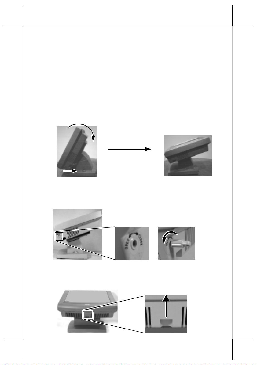
OPENING CABLE COVER
Please first push the lock/release lever on the base backward to adjust
the stand to the most horizontal position for ease of operation.
Insert the tip of the latchkey into a latch hole on one side near bottom
of the main unit. Turn this key counterclockwise to the end. Do the same o n
the opposite side. Be sure to take the key out of the hole before doing next
operation.
Then push the lock/rele ase lever on the base backward to adjust th e
stand to the most horizontal position for ease of operation. Open the cable
cover by pulling at the removal hollow.
Push lock/release lever
back and turn panel to
most horizontal position
Turn Counterclockwise
Then Take Out The Latchkey
Pull The Removal Hollow
Toward The User
Part 4
Page 5
CONNECT/DISCONNECT CABLES
After removal of the cable cover, the connector area will be accessible
then. Please disconnect every cable before separation of main unit and the
adjustable stand assembly. When later the main unit and stand assembly are to
be re-assembled for application, please connect all required cables to the
appropriate connectors. Please make sure that each connector is connected to
the right port with the correct orientation. Damages due to incorrect
connection or orientation are not covered by product warranty!
Some connectors, such as the LAN connector and the cash drawer
connector have to be inserted until a click is heard. It is recommended that
connectors such as the external VGA connector, the LPT port connector and
the COM port connectors, be screwed into place once seated. If the COM1 port
must be used, the COM1 terminator that occupies the COM1 port must be
removed. However, when using the COM1 port, be sure to use devices that
provide proper hardware handshaking sign als in order to keep the cash drawer
control features. A serial mouse is one example of a device that does not
support handshaking.
Adjust the slack of each cable and close the cable cover. Use the same
plastic latchkey that is used when removing the cable cover, but be sure to turn
it in the clockwise direction to lock the cover in place. Re-adjust the tilt angle
of the screen for best viewing.
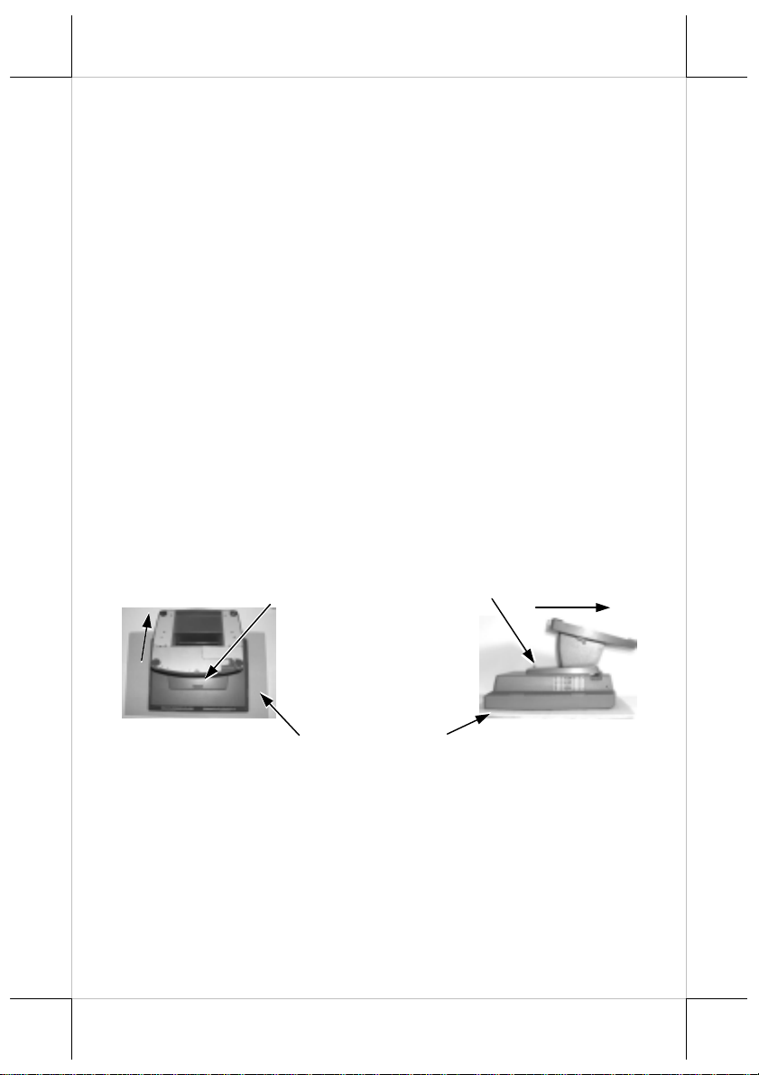
SEPARATING MAIN UNIT
A soft clean flat surface, such as a piece of cloth on the desk.
In order to settle the touch terminal properly in a point of sale system,
all the cable connections have to be routed through its base, the stand assembly.
Therefore, please press the lock/release button at the rear side to separate the
main unit from the stand assembly after all cables in cable cover disconnected.
For easy operation, it is most recommended to lay the system facing
down on front panel over a soft clean flat surface first, such as a piece of cloth
on the desk. Press the button and slide the stand assembly downward (as
viewed from the main unit) to detach the stand assembly away from the back
of the main unit could then be an easier operation. This approach can also be
Press the Lock/Release button
and slide the stand assembly
downward (as viewed from the
main unit) to detach it from the
main unit.
Push this way
Part 5
Page 6
applied when later on the main unit and the stand assembly have to be reunited.
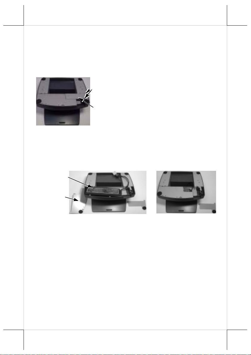
OPENING STAND ASSEMBLY
Take the adjustable stand assembly and turn it up side down to show
the bottom of the base. Now, unscrew the 2 screws on the cable passage cover
and take the cable passage cover away to show the cable passage.
If there is no need to install the
Screws
optional UPS battery here, please skip
the next paragraph and start routing
cables through the cable passage.
Cable
Passage
Cover
Otherwise, please remove the four
screws holding the battery cover to
install the battery.
INSTALLING UPS BATTERY
Place the optional UPS battery in the battery compartment (shown
below left). Screw on the battery cover and route the battery cable through the
base. Please pay particular attention to the environment requirement for UPS
battery in next chapter “USING THE TOUCH POS”.
UPS Battery
Removed
Battery Cover
CASH DRAWER
The Jiva series is able to control the printer (direct) drive type
Posiflex cash drawers. Among them, it is recommended that the Posiflex CR4000 or CR-4210 be used since the terminal has been designed to compliment
this cash drawer both mechanically and electrically.
The Jiva series will directly control the cash drawer using the cash
drawer port (CR) both to operate the opening mechanism and to monitor the
drawer open status. Both functions may be accomplished under software
control of the COM1 serial port through the interface cable supplied with the
cash drawer (P/N: 20863018010). Connect the CR cable fro m “CR” port to th e
connector marked: “signal cable from POS Printer” at the rear of the cash
drawer.
The Jiva series offers another advanced feature in the cash drawer
control by using the optional split cash drawer control cable CCBLA-238.
Part 6
Page 7

Window
Connect the 6 pole plug of CCBLA-238 to “CR” port and connect each 8 pole
plug to the connector marked “signal cable from POS Printer” at the rear of
one of the cash drawer. In this way, the Jiva series is capable of controlling
two cash drawers independently through software command.
ROUTING THE CABLES
Place all the cables required for connections to the Jiva TP/LT-5700G
or Jiva TP/LT-5800G except those for special application purposes into the
cable passage. Insert one end of the cable passage cover under the adjacent
cover plate and screw on the two screws. Be sure not to damage any of the
cables during this operation.
Now, turn the adjustable stand assembly back to normal orientation
and arrange all cables to come out of the area for mounting main unit from the
bottom edge for ease of later operation.
Fix this End of the Cover First
Route Cables under the Cover
Connect this End to Main Unit
This End to Other Devices
PREPARING THE MAIN UNIT
On the back of the main unit, there are 4 matching pegs and a service
window. Push open the service window in the direction as indicated in the
picture, one can find a button cell battery socket, two 1 x 2 (JP6, 9) and two 1
x 3 headers (JP11, 16) with 1 jumper each and two 2 x 3 header (JP13, 14)
with 2 jumpers each. Though it is possible that the contents in the service
window may change as time develops.
Service
Push
Open
To The
Right
Risk Of Explosion If Battery Is Replaced By An Incorrect Type
Dispose Of Used Batteries According To The Instructions
This battery socket accepts a 3 V button cell Lithium battery (CR2032)
4 Matching
Pegs
CAUTION
Part 7
Page 8

required to support the system real time clock. The jumpers in this window are
designated for VGA port and COM port power supply function. Please con sult
your dealer for technical support on setup of these jumpers. A new Lithium
battery can support the system RTC for about 3 years. After the battery is
nearly exhausted, the user must change a new battery otherwise the system
RTC and system configuration setup will be lost.
INSTALLING UPGRADE KIT
Please follow the instructions in the manuals delivered with the side
mount upgrade kit: KP100, SD100, SD200 or BC100 and the rear top mount
upgrade kit PD302 to fit them in Jiva 5700G / Jiva 5800G construction.
The USB power arrangement in this system has been particularly
designed to help smooth start up of the fingerprint sensor in SD200.
WIRELESS PRINTER
The whole Jiva series can access the Posiflex wireless thermal printer
PP7700. To do this, a wireless Dongle DG2000 for this printer must be
separately purchased and installed to one of the serial COM ports in Jiva
system. Please enable the + 5 V DC power support for this COM port. Notice
2 hooks on rear side of the Dongle and also 2 hooks on either top corner on
rear side of main unit of the Jiva system. Match the hooks to mount the Dongle
to either corner of the Jiva system. Should there be more than 2 Dongles to be
installed in the application for the advantage of several fixed predetermined
connections without need for connection alteration in process, the third Dongle
and afterwards have to attach to the appropriate positions by use of the selfadhesive tape because Jiva series supports only 2 rear top corners with hooks.
The Posiflex wireless connection supports various application
environments from having single Dongle to control single wireless printer to
having single Dongle to control multiple wireless printers and further to having
multiple Dongles to control multiple wireless printers. Unlike usual wireless
printer solutions that requires the application software to use the printer server
in WLAN the Posiflex wireless connection supports a genuine virtual cable
connection thus supports the application software to use even the so-called
direct I/O method for controlling the printer. The user may install the relevant
driver prior to the application software if the software did not include the
Hooks On Rear Side Of Dongle
Dongle Hooked On Rear Top
Corner Of Jiva System
Hooks On Rear Side Of Jiva
Part 8
Page 9

Posiflex wireless connection driver elements. The driver can be found together
in delivery of the wireless printer or the Posiflex Product Information CD of
version 1.9 or above, or please find it on our web http://www.po siflex.com
http://www.posiflex.com.tw
or
JOINING MAIN UNIT AND STAND
Match the matching pegs on the back of the main unit against the
matching holes on the stand. First aim the matching pegs toward the upper
round part of the hole and make sure that all pegs are inside the holes. Then
slide the main unit down to move the pegs into the lower slot part of the holes
till it clicks. Note that all the cables come out of the stand from the lower edge
and won’t get trapped by this mounting operation. If later on you want to
remove the main unit from the stand, you’ll have to press down the
lock/release button on back of the stand at the time lifting the main unit.
Matching Holes Matching Pegs
Round Part
Slot Part
Removal Hollow
CONNECTING CABLES
Connect the cables required to the appropriate connectors. Please
make sure that each connector has to be connected to the right port in the right
orientation. Some connectors have to be inserted till a click is heard such as the
LAN connector. It is recommended to screw on the connector once it is
inserted such as the external VGA connector, the LPT port connector and the
COM port connectors. Adjust the slack of each cable and close the cable cover.
Use the same latch key as when opening the cable cover but this time turn it
clockwise on both sides to secure the cable cover on the main unit. Adjust the
tilt angle of the main unit for best viewing effect in the application.
CAUTION: On doing any insertion or extraction of any connector, please
always hold the connector head itself instead of pulling on the
cable wire. Failure to do this could damage the cable and jack
that is considered as an artificial destruction and is not
covered by the warranty.
Part 9
Page 10

WALL MOUNTING
The major part in the wall mounting kit is a bracket as shown in the
picture. Screw the bracket against the wall for mounting the Jiva TP/LT5700G / Jiva TP/LT-5800G in the direction that the wider parts of the
matching holes are at the top as shown in the picture below. Align the four
matching pegs on the back of the main unit with the four matching holes in the
bracket to hold the main unit in the similar manner as installing the main unit
onto the stand assembly. The stand assembly is not engaged in wall mount
operation.
Wall Mount Bracket
Show
this
side
out.
Matching Holes
Screw
Holes
LOCATION FOR INSTALLATION
As the stand assembly is not involved in wall mount installation, the
space required for wall mount application will take only the main unit into
consideration. So the space required is 375 mm in width and 315 mm in height.
For desk top/counter application, the adjustable stand assembly
requires a base of 270 mm deep and 260 mm wide. However, please take also
the main unit into consideration. If the main unit is tilted to near vertical
position, the total height is 360 mm. When the main unit is tilted to near
horizontal position, the total height required is 275 mm.
OPERATING SYSTEM RECOVERY
For Jiva TP/LT-5700G, if not using a remote boot operating system,
the operating system exists in the Compact Flash Card. Therefore, once the
Compact Flash is damaged for any reason, the thin client may fail to boot. A
bootable new Compact Flash Card will be required to have the
workstation back to work. Please follow instructions given by the System
Integrator to deal with situations like that. One more advice for CF Card
application is that in spite of the fact that it is used in the way like an ordinary
HDD, usual system management utilities such as FDISK.EXE or
FORMAT.COM shall never be used on CF Card otherwise the boot sector
of operating system itself may be damaged and causing the CF Card no longer
bootable.
For Jiva TP/LT-5800G, the operating system exists in the HDD. Once
Part 10
Page 11

the software system on HDD collapses, it is possible to restore the operatin g
system onto a physically intact HDD with use of the Recovery CD that comes
with the preloaded operating system. Please follow the instruction from your
system integrator for system / software restoration. Follow the instructions
below for operating system recovery only if your system integrator does not
advise otherwise.
For the Jiva TP/LT-5800G preloaded with Windows XP Pro or Windows
98 on HDD, Posiflex provides recovery CD delivered with the touch terminal
for the preloaded operating system. The System Integrator shall take care of
software restoration after OS recovered. A Posiflex supplied USB interface
CDROM drive will be required for such action. Other brand CDROM drive
may require its specific driver different from what supported in the recov ery
CD.
Please use the recovery CD in rescue operation only. Using it
otherwise may wipe out whatever stored in the HDD! All upgrade devices
drivers needed for manual installation in usual way are available in the
subfolder “\drivers” in OS recovered HDD and the latest versions of these
required drivers will be available on our web: http://www.posiflex.com.tw
Now please follow instructions from your system integrator for
software recovery.
Please refer to the “System Protection” section in chapter “USING
THE TOUCH POS” for guidance on the Time-Machine-like system recovery.
.
OPERATING SYSTEM INSTALLATION
This product is a highly professionalized equipment. The installation
of an OS into a machine without any preloaded OS could constitute major
difficulty for average user who either has barely limited technical knowledge
of this professionalized equipment or is insufficiently equipped with necessary
facilities to accomplish such a task. Therefore, installation of an OS into a
system without preloaded OS is highly discouraged. Posiflex shall not be
responsible for any technical support to questions arisen due to non-preloaded
OS.
IDE CABLE KIT (FOR JIVA 5800G)
There are an IDE connector and a 4 pin power connector in the I/O
area of Jiva 5800G designed for software installation occasions. Please use the
optional IDE cable kit for such occasion to connect both data and power from
the main unit to the IDE device such as an internal type IDE interface CD
ROM drive. Please pay particular attention to each cable orientation in the
connection and fix if there is any grounding terminal for cable shielding to
suitable screw on metal casing. Remove every connection when the software
installation is done.
Part 11
Page 12

USING THE TOUCH POS
APPLICATION ENVIRONMENT
It is very important that you check the following operational
guidelines:
Ventilation
This terminal must NOT be operated in an environment with
restricted ventilation. The installation should be such that there is at least
25mm air clearance around any top or side ventilation holes. The installation
must also be such that there is a free flow of air around the unit at ALL times.
Operating Environment
The equipment must not be operated or stored in extremes of both
temperature and humidity/moisture.
(Operating range 5°C to 40°C and up to 80% humidity – non
condensing)
UPS Battery (option)
General care:
The UPS battery is consumables beyond product warranty. Please
note the following to preserve its serviceability as long as possible. When the
equipment is to be powered off for more than few days, please disconnect the
battery from the system and reconnect it and turn on the system to recharge the
battery for 1 ~ 2 hours every 3 months if the temperature is lower than 30°C.
Recharge for 1 ~ 2 hours every month if the temperature exceeds 30°C.
When an UPS battery is installed in this equipment, the environment
should keep below 30°C to protect the life of the battery. Temperatur e above
40°C must be strictly avoided as it could cause termination of battery life and
unexpected result even if the battery is not in work. The UPS battery can
support basically the data preservation and smooth running of the system
during intermittent or few minutes power failure and will be automatically
recharged when system tur ned on with AC power presence. However, if the
AC power outage is known to last for more than few minutes (3 ~ 8 min.
depending on loading), it is advisable to turn off the system instead of using
the battery up while repeatedly using it up or improper maintenance
reduces the battery life dramatically. Please be particularly reminded to
disconnect the UPS battery if the system is to be left OFF for more than 7
days to prevent possible damage. Please be alerted that a study on brand new
well-charged battery indicates that leaving a battery connected without system
power on for recharging for 10 days or more or even storing the battery
unconnected for more than 9 months could degrade the battery capability. A
Part 12
Page 13

well-maintained battery can be expected to prov ide adequ ate s ervice for 1 year.
Battery replacement:
In the power management circuit in this POS system, there is a handy
battery monitor feature to help user find out when an UPS battery should be
replaced. The battery monitor will always first measure and check the UPS
battery to see if the UPS battery is already incapable of service or if there is
any sign for the possible critical fault development in the battery before it
allows the charging operation to the UPS battery. Reason for such extra check
is that indifferent recharging on a battery with some critical fault like micro
short circuit will not only boost the fault development in and total failure of th e
battery but also can result in confusing system malfunction.
In the preloaded OS, there is a built in utility Power Manager that will
interface the UPS battery monitor status with user. When a healthy UPS
battery is added to an originally UPS function disabled system, the Power
Manager will enable the UPS function automatically. However, when battery
monitor disables the battery charging as designed while the UPS function of
the system is originally enabled, in other words the UPS battery is found out of
order if actually installed, there will be a popup message asking the user to
agree disabling the UPS function. The system will operate under deactivated
UPS function no matter agreed or not. However, the monitoring goes on and
the popup message will come back on next system power up boot if not agreed.
In any case, please replace the used up UPS battery at power off if the battery
is well connected there but found inoperable by such messages.
Power Supply
The operating voltage range of the power adaptor should cover the
local power supply for proper operation. The power cable, the power outlet
and any power fusing arrangements must conform to local safety regulations.
Please never do any connection / disconnection when system is still
powered on. Please always keep the external power adaptor in a free air
circulation.
POWER ON/OFF
There must always be at least 10 seconds waiting before switching on
again once the system is powered off successfully.
LED Indicator
There is an LED in the logo area or under the printed logo and serves
for several purposes. The relationship between LED status and other
Part 13
Page 14

conditions is summarized in following table:
LED Status System Status External Power UPS Battery Powering Up
Off Off Off Not present Not possible
Off Off Off Present Not allowed
Green Off On No influence Allowed
Blue On On No influence Not required
Blue/flash On Off Activated Not required
Green/rapid
flash
On Off
Running at
low capacity
Not required
Hardware Power Switch
The power switch located at left side of the main unit is a slide type
switch. This switch controls the power on/off of the system. This switch turns
the system on when slid downward, only when external power is present. The
switch will always spring back to its original position when pressure is
removed. This switch turns the system off when slid downward again during
power on status. However, if the system hangs due to any reason such as
software resource conflict a simple slide of the switch may fail to turn off the
power. In this case, please utilize the forced power off feature by pressing the
switch downward, and holding for within 10 seconds. In case the turmoil is so
vigorous that some hardware registers may be confused causing trouble for
system restart or even this forced power off, please disconnect the UPS battery
if installed and the AC power supply for few minutes. This may allow all
hardware registers to reset.
This switch can also be programmed as an ON only switch. That
means, if the application program issues a command compliant with the Jiva
series technical manual, this switch will always turn the system on when
activated, but will not power off the system when depressed again (the forced
power off feature will not work in this mode). When using this feature, please
make sure that the software application has the ability to power off the
machine. In preloaded Windows, “Posiflex Power Switch Manager” in
“Posiflex Tools” in the Program Files helps managing these functions.
Software Support
The Jiva series provides a software power off command for
application program maneuvers. The Jiva also provides a specific means for
the software to detect if the system is working on external or UPS battery
power. Due to this feature, compatible software applications have the ability to
change operating conditions when running on standard/backup power. The
software programmer may take reference from the Jiva technical manual to
apply such features.
Part 14
Page 15

AUTOMATIC POWER ON
There are several ways supported by this system to perform an
automatic boot up as long as external power is supplied to the system.
Procedures for each method are described below.
By RTC Alarm preset
1. Preset the system to timely boot up by pressing “Del” key at
powering up this system to enter system BIOS CMOS setup.
2. Select “Power Management Setup” and enter “PM Wake Up Events”.
Go to item “Power Up by Alarm” and change the setting to
“Enabled”.
3. Alarm setup detail will appear. Set the alarm as wished then press
“F10” key to save and exit CMOS setup.
4. This system may be powered off and will automatically boot up at
the preset alarm time.
By RS232 MODEM Ring up
1. Preset the system to boot up on RS232 MODEM ring by pressing
“Del” key at powering up this system to enter system BIOS CMOS
setup.
2. Select “Power Management Setup” and enter “PM Wake Up Events”.
Go to item “Ring Power Up Control” and change the setting to
“Enabled” then press “F10” key to save and exit CMOS setup.
3. Connect a RS232 MODEM to any of COM2, COM3 or COM4 and
to a proper telephone line. This system may then be powered off and
will automatically boot up at the MODEM ringing.
By LAN Wakeup
For LAN wakeup, an operating caller system connected through LAN
to the system to be called is required. It also requires a qualified networking
technician to check the LAN chip ID of the system to be called for the caller
system to wake up.
DISPLAY RESOLUTION
For best viewing result please set your display re solution at 1024 x
768 with high color.
In configuration of system memory, max. 64 MB can be shared as the
video memory.
External LCD Monitor
The external VGA port in the Jiva TP/LT-5700G / Jiva TP/LT-5800G
supports TM4115 touch monitor, LM6112 LCD monitor or TM6112 touch
monitor. This port supports either mirror mode (identical image) or extended
Part 15
Page 16

mode dual display function for Win98 or WinXP. To support th e DC power to
these Posiflex monitor, use the DC adaptor to connect into the monitor or
VGA cable or purchase another type of VGA cable and set an internal jumper
in Jiva TP/LT-5700G or Jiva TP/LT-5800G to supply the required power
through the VGA connector.
SYSTEM PROTECTION
In the Posiflex POS system deliver ed with preloaded OS, there is a
function built in for system protection. A screen as below will pop up for a
short period of time in operation system booting up stage.
In normal application, nothing has to be done and the system boot up
continues. However, this system protection function is provided for our end
users to fight against enormous virus attacks or malicious system invasions
nowadays or even some possible system crash. Please connect a PS/2 keyboard
to KB port of the system to engage this function only when necessary. Press
the three key combination of “Ctrl” + “Alt” + “F12” at the above s creen to g et
a screen display as below.
Part 16
Page 17

Please be solemnly alerted that the system restore operation means the
irrecoverable erasement of existing data or system setup, it is strongly advised
to press “Esc” key to avoid such miserable damage if there is any doubt.
Pressing “F4” key at this screen will save the current status of the
whole system and the earlier saved status will be cleared at the same time.
Therefore, please do this save only when you know that your curren t system
status is “safe” and “clear”.
Pressing “F3” key at this screen will restore the last saved system
status. Please be aware that whatever data or any system change ever since last
“save” will be permanently lost by this restore operation. Therefore, do restore
only after you have made all the necessary data preservation!
Pressing “F2” key at this screen will restore your system back to the
“OS + application software” situation that your system integrator has put into
protection with technical help from Posiflex before they deliver you this POS
system with software solution. Please note that whatever data or any system
change you have made on this system will be lost by this action. Pressing “F2”
key will have no response if your system integrator did not do the protection or
if you have erased their effort by action in next paragraph.
Pressing the three key combination of “Ctrl” + “Alt” + “F1” will
restore your system right back to the “pure OS” status. Please never take this
action unless you know exactly what you are doing and what to do next! The
whole process may take quite a while.
TOP MOUNT CUSTOMER DISPLAY
Please follow the instructions on the manual that comes along with
the top mount customer display PD302 when it is installed.
SERIAL PORTS – COM1/2/3/4
In Jiva TP/LT-5700G / Jiva TP/LT-5800G, there are 4 serial ports
available except those models using RS232 touch interface (Infra Red type
touch panel). All the serial ports can supply a +5 V DC through pin 9 after
proper jumper setting change. All 4 ports are standard RS232 serial ports as
status at delivery.
When a serial Modem is to be used in Jiva TP/LT-5700G or Jiva
TP/LT-5800G, it is most recommended to use COM2 or COM3 port for this
purpose. In this way any hardware resource conflict is eliminated and the
MODEM ring up function can be supported. For Infra Red type touch control
models (it uses RS232 interface), COM4 is occupied and covered. Please
never try to open the cover. Otherwise the product warranty is voided.
Part 17
Page 18

SOUND PORTS
The audio port on Jiva TP/LT-5700G / Jiva TP/LT-5800G supports a
Microphone in and a line out jacks. The internal audio output port supports
line output signals and requires power amplifier for connection to speaker
unless the option of audio amplifier and a pair of slim type speakers built in the
cable cover area are ordered at the beginning.
LAN BOOT
If the system integrator arranges the TP/LT5700G to boot from a
LAN server, he may have revised the system BIOS installed in TP/LT5700G
to a specific program (that depends on the LAN communication protocols
involved). In this case, there will be a choice between LAN boot and local boot
at boot-up (powering up) process. And it is advisable to select for LAN boot
for this application and follow whatever the boot server defines.
TOUCH PANEL (for TP models only)
All paragraphs below are applicable in TP-5700G and TP-5800G only.
The user of LT-5700G and LT-5800G can ignore them and consider this user’s
manual ends here.
Mouse Emulation
The touch panel in Jiva TP-5700G / Jiva TP-5800G uses either a PS2
interface or an RS232 interface. When its driver is properly installed, this
touch panel works exactly like a standard mouse. However, if the system is
running under safe mode due to a previous improper shutdown or for any other
reason, most drivers are disabled in this mode and the touch panel calibration
may not coincide with the mouse pointer. It is recommended that a standard
USB mouse or keyboard be used in this mode.
All the below mentioned mouse emulation functions can be
manipulated through relevant software. The system can give a beep when the
touch panel is touched and can respond as if the left button of a mouse is
clicked at the point touched. If the point touched is dragged across the screen
surface, it can respond as though it is using the mouse drag and drop feature. If
the point is touched, released and touched within a short time interval, it will
simulate double-clicking left button of the mouse. To obtain the effect like
clicking on the right button of a mouse, touching any point on the screen
surface after touching the right-click sticky button results as a click on the right
button of the mouse at that point can work for PS/2 touch controller type under
Win2000 and WinXP and for RS232 touch controller under Win98. For the
PS/2 interface touch panel controller in Windows 98, touching the screen for a
while followed by a slight move of the touch without leaving the screen
surface will result in a right button mouse click.
Part 18
Page 19

Posiflex Touch Terminal Manager
A program named “Posiflex Touch Terminal Manager” is installed in
the preloaded Windows system with a PS/2 interface touch panel controller.
This program can also be obtained by download from the POSIFLEX web site.
This program can be engaged in the program group “Posiflex Tools”
and it controls the beep generated when the touch panel is touched, the detail
in right button click emulation, and also provides touch panel re-calibration.
RS232 Touch Controller
If the Jiva TP-5700G or Jiva TP-5800G purchased is the leading edge
Infra Red type touch models, the touch panel uses an RS232 interface
controller. The “Posiflex Touch Terminal Manager” above should be
disregarded. In these models, the COM4 position of the system will be covered
in the connection area. Removal of this cover will void the product
warranty!!
Once the RS232 touch controller driver is installed, the user can
utilize it to calibrate the touch screen, define mouse button emulation modes,
enable right button emulation or define the click sound’s tone and duration.
Please click “Start”, “Settings” “Control Panel” and “Elo Touchscreen” or just
click the “elo” icon in tool tray to engage this utility. However, with this touch
controller driver, certain display mode like full screen display of Windows
DOS box should be avoided.
If, for any reason, the user wants to remove the driver for the RS232
touch controller, please select “MonitorMouse” in the program list for removal.
Part 19
 Loading...