

DS-200 / DS-210
Dock Station
User Manual
DS-200
DS-210
Package Contents
DS-200 unit (x 1)
12V/60W power adaptor (x 1)
Desktop mounting kit pack x 1
(including 2 fixing screws, 2
plastic anchors, and 1 desktop
mounting bracket)
User manual (x 1)
Package Contents
DS-210 unit (x1)
12V/100W power adaptor +
power cord (x 1)
Thermal paper roll of 80 mm
width (x 1)
Spacer plate for thermal paper
roll of 58mm width (x 1)
Desktop mounting kit pack x 1
(including 2 fixing screws, 2
plastic anchors, and 1 desktop
mounting bracket)
User manual (x 1)
Product Features
Multiple I/O ports
Wi-Fi printer (802.11b/g/n 2.4GHz) (for DS-2 1 0 onl y )
Charger for MT-4008W tablet PC
12530901010 Ver. Original
http://www.posiflex.com
1
Views of the DS-200/DS-210
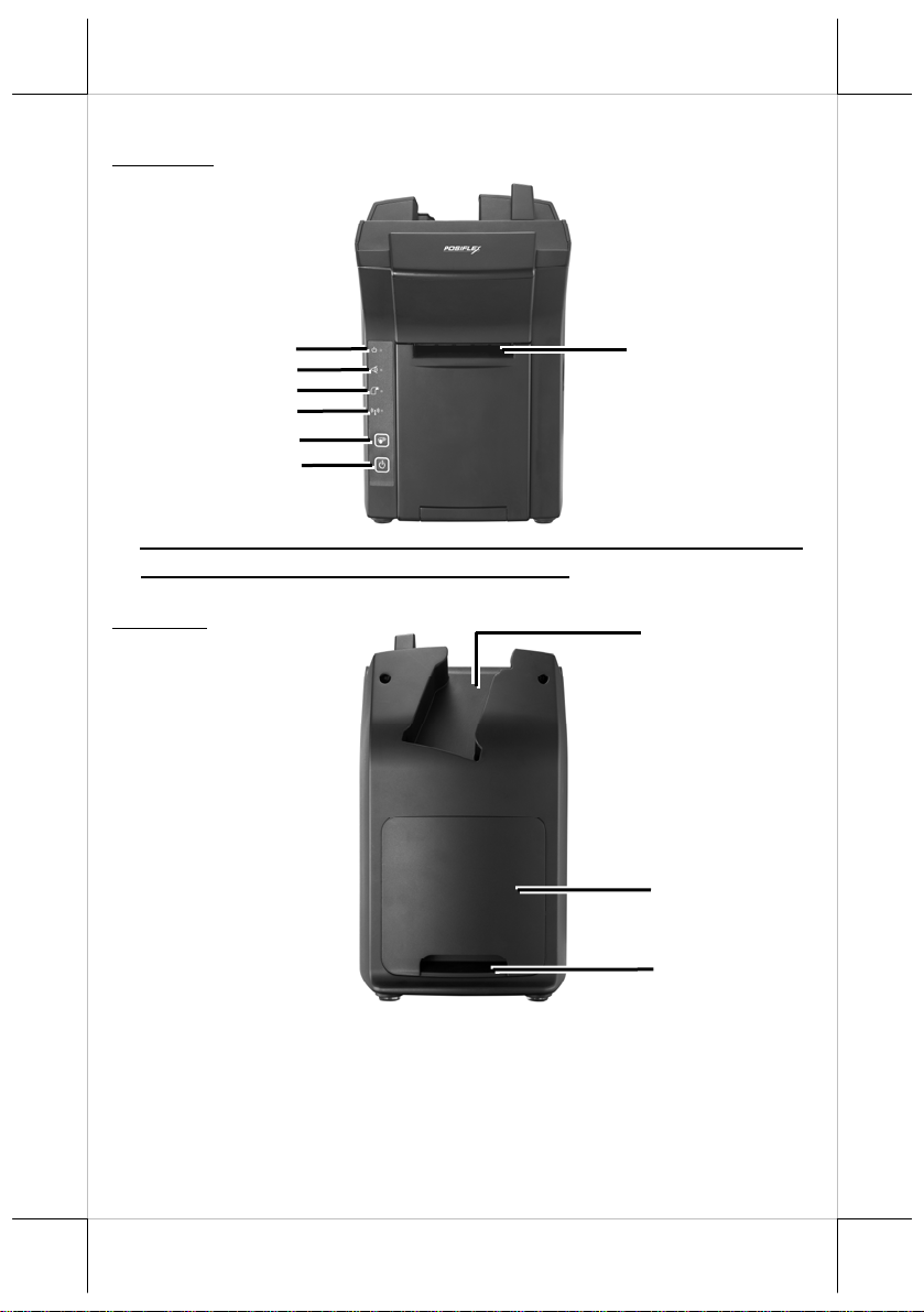
Front View
Power LED Indicator
ror LED Indicator
Er
Paper-out LED Indicator
Printer Wi-Fi Indicator
Feed Button
Power Button
※ Error LED Indicator, Paper-out LED Ind
and Feed Button are provided for DS-210 only .
Rear View
Paper Roll Exit
icator, Printer Wi-Fi Indicator,
Pistol Grip (PG-200) Holder
Bottom I/O Cover
Cable Exit
2
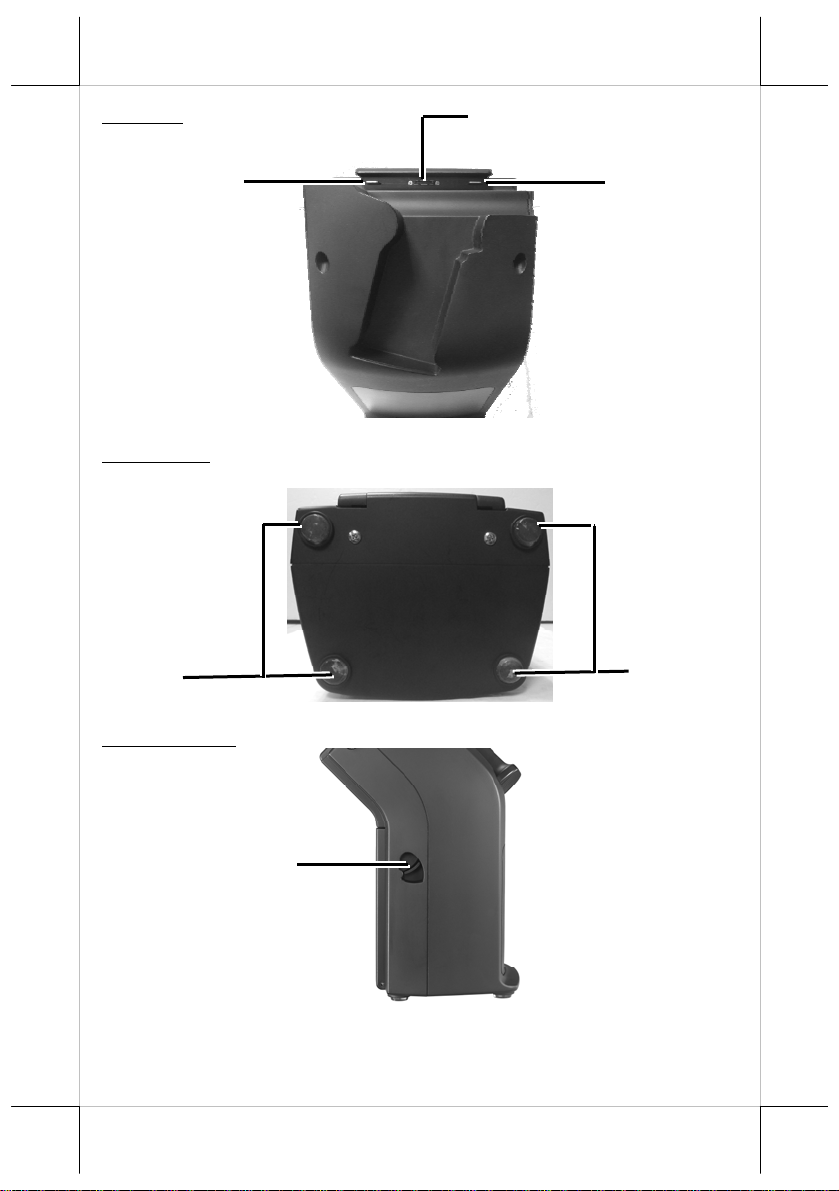
Top View
uiding Wedge
G
Tablet (MT-4008W) Connector
Guiding Wedge
Bottom View
Cushion
Right Side View
Paper Roll Cover Release Lever
Cushion
3
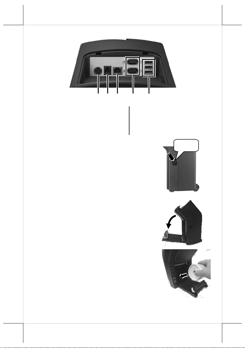
View of I/O Interface of DS-200/210
1
2
4
3
5
1 12VDC-IN Power Jack 2 RJ11 Cash Drawer Port
3 RJ45 LAN Port 4 DB-9 Port
5 USB 2.0 Port
Loading a Paper Roll
1. Press down the paper roll cover release lever to
release the paper roll cover.
2. The paper roll cover ejects. Then, open the paper
roll cover manually.
3. Drop the 80mm-wide thermal paper roll inside
the paper roll compartment of the printer, as
shown in the right figure.
Press
4
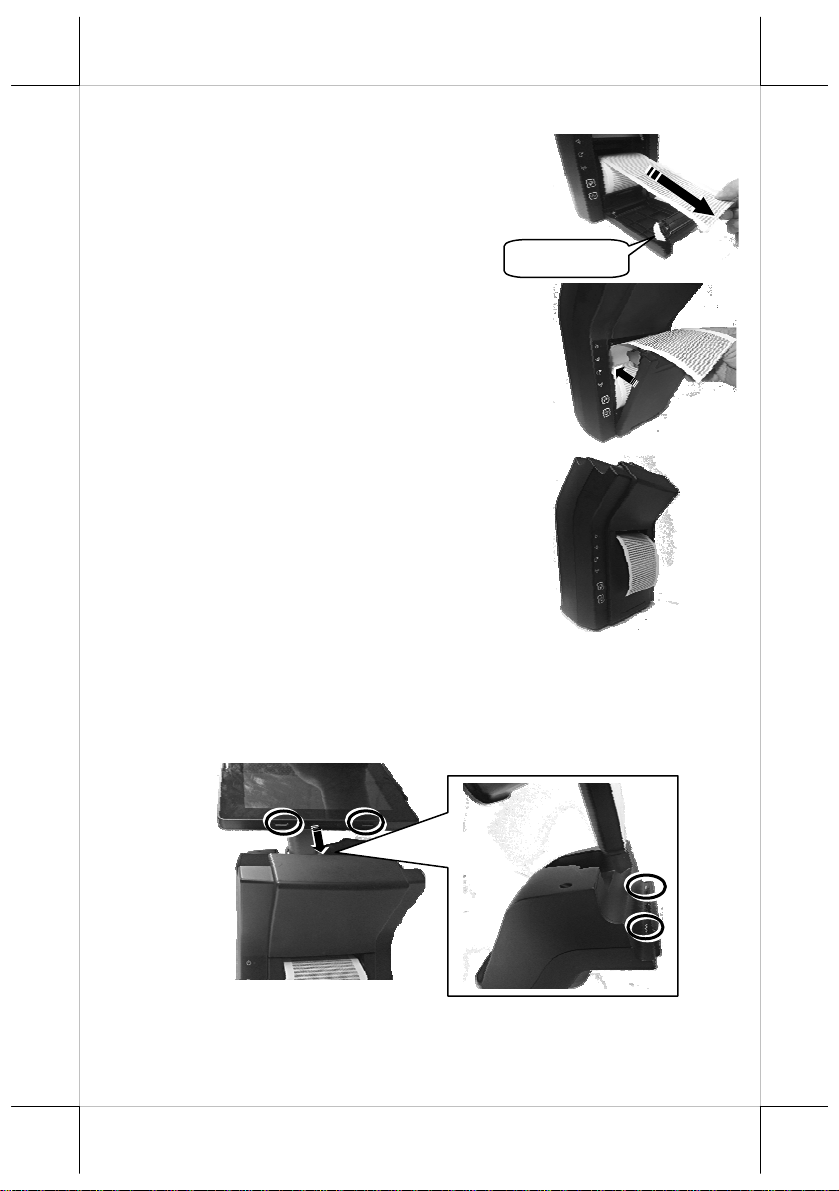
4. Drag the paper roll to the portion where the
paper cutter is installed.
Paper Cutter
5. Close the paper roll cover and make the tail of
the paper roll come out of the track between the
paper roll cover and the front cover.
6. Determine that the paper roll is completely
loaded in the paper roll compartment of the
printer and the paper roll is dragged out of the
track between the paper roll cover and the front
cover.
Placing the MT-4008W on the Dock Station
1. Align the two dock station locking holes on the MT-4008W tablet PC with
the two guiding wedges on the dock station. The tablet PC connector on
the dock station is then fully connected to the dock station connector on
the tablet PC.
5
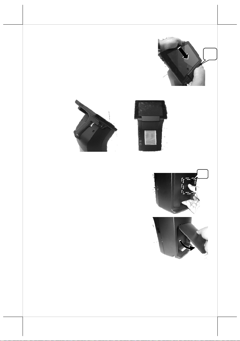
2. Hold the portion A and press the MT-4008W
tablet PC to connect firmly to the dock station.
3. Determine that the tablet PC is completely placed on the dock station.
Connecting Power Adapter and I/O Cables
Follow the steps listed below to open the bottom I/O cover and connect cables.
1. Press the portion A with thumb.
A
2. Lever the protective cover in the direction
indicated by the arrow in the right figure.
6

3. Remove the protective cover.
4. Connect power adapter and I/O cables to the
I/O port of the dock station.
5. Make the protective cover join to the wedge
portions of the rear cover of the dock
station.
6. Determine that the protective cover is well
wedged to the wedge portions of the rear
cover of the dock station. Then, gather the
I/O cables together for cable arrangement
7. Cover the I/O ports of the dock station with
the protective cover.
7

8. Determine that the I/O ports are covered and
the cable passes through the cable exit.
Cable out
Mounting the POS onto a Table
To avoid the dock station from backward tilting and wagging when a user
touches the LCD panel of MT-4008W set on the dock station, use the desktopmounting kit shipped with the DS-200/210 to hold and secure the dock station
firmly on a table. Please follow the steps below to mount the dock station.
1. Determine a position of a table onto which the dock station is mounted.
Then, take the desktop mounting bracket out of the desktop mounting kit
pack. Through the 2 holes formed on the bracket, drill 2 holes on the
table and plug 2 plastic anchors into the 2 holes. Then, hold the bracket
and then apply the 2 self-tapping screws into the 2 holes to secure the
bracket.
2. Align the 2 screw bolts on the bottom of the
dock station with the 2 tracks of the bracket.
3. Push hard the dock station backward along the 2 tracks of t he brac ket on
the table to firmly secure the dock station.
8

Charging the PG-200 Battery Pack and the MT-4008W
After completing in placing the MT-4008W tablet
PC provided with the PG-200 on the dock station and
then in plugging the power adaptor into the power
jack on the dock station, as described above, plug the
AC power adaptor cord into an electrical outlet for
starting to charge the PG-200 battery pack and the
tablet PC.
CAUTION!
1. When the tablet PC gives you a message indicating it will run out of
power, please fully charge the battery to avoid data loss.
2. Use only the power adapter that comes with your device. Using a
different power adapter may damage your device.
At this time, the battery of tablet PC will be firstly charged. When the battery
of tablet PC is fully charged, the battery pack loaded in the pistol grip will be
then charged. When the battery pack loaded in the pistol grip is fully charged,
the “FULL” LED indicator of the grip turns green.
When the tablet PC operates for a period of time, because the battery pack
loaded in the pistol grip constantly supplies power to the tablet PC, the battery
will be consumed. At this time, charge the battery pack with a power adaptor
through the dock station or change the battery pack immediately.
Powering ON the Dock Station
1. Press the power button of the dock station.
9

2. The power LED indicator stays bright and solid
blue when the dock station is powered ON.
Installing the Wi-Fi Printer Tools (for DS-210 ONLY)
The Wi-Fi printer tools make wireless connection between the DS-210 and the
MT-4008W tablet PC and allow you to easily do wireless settings of the Wi-Fi
printer. Follow the steps listed below to install the Wi-Fi AutoConnect.
1. On disk (C:) of your MT-4008W tablet PC, tap This PC Local Disk
(C:) Drivers WLPPMgr115. In the folder of WLPPMgr115,
double tap the Setup application for installation of the Wi-Fi Auto
Connect tool.
2. You will be guided through the installation process. When the tool
installation is completed, tap Finish.
10

Operating the Wi-Fi Printer Tools (for DS-210 ONLY)
After completion of the Wi-Fi Printer Tool installation, you will see the tools,
WIFIConnectTool and Posiflex LAN WiFi Printer Manager
pane of Microsoft Windows® 8.1, as shown below.
, on the Apps
WIFIConnectTool
The WIFIConnectTool is designed for you to easily connect your MT-4008W
tablet PC in wireless manner to the DS-210 printer and also for you do the
printer test.
1. Tap and hold WIFIConnectTool (1), and then tap Run as administrator
(2).
1
2
11

2. The WIFIConnectTool is opened.
Note:
a. Do NOT change the Printer IP addres s at
your first use. The default printer IP
address is 192.168.192.168. Only after
successfully connecting a host, you are
allowed to change the printer IP address.
b. The default Host IP address is 192.168.192.33. You are allowed to
change the host IP address depending upon your request.
c. The default ADHOC printer SSID is POSIFLEX.
3. Tap Go to make your tablet PC start to
communicate with the DS-210.
4. Now, you see the “WAIT” message.
5. After several seconds, you see a reply from
the DS-210 printer you are connecting to.
12

6. When the tablet PC successfully connects
to the DS-210 printer, you will see the
“OK” message.
7. Tap Test Start to do a printing test.
8. In this step, you see the message in the
column of Status indicating “Connected”
and that in the column of Lines indicating
“Data … sent”, which means that the
wirelessly connected printer is printing data
for the test.
9. To stop the printing test, tap Test End.
13

Posiflex LAN WiFi Printer Manager
The Posiflex LAN WiFi Printer Manager is designed for you to easily change
the IP address and/or SSID of the DS-210 printer. After you use the
WIFIConnectTool to successfully connect the tablet PC to the DS-210, you
can then use the Posiflex LAN WiFi Printer Manager to change the IP address
and/or SSID of the DS-210 printer.
1. Tap Posiflex LAN WiFi Printer Manager
on the Apps pane.
2. Select the item --
PP6900/PP8800/PP9000/MT4008(DS210)
-WIFI-Printer (1) and then tap OK (2).
2
1
3. The m
anager starts to search connected printers around.
4. After the manager finds connected printers around, tap a con nected printer
of which the settings you want to change (1). Then tap Change Settings
(2).
2
1
14

5. In this step, you can change settings per your request. After completion of
change, tap Save to Module.
Note: If you want to change WiFi Mode from Adhoc to Infra, continue
following the steps listed below for successful change.
6. Whe
n you see the message showing “Save to Module OK” on the
window (1), tap Exit (2).
2
1
7. Tap Ex
it to exit from the manager.
8. Tap and hold WIFIConnectTool on the Apps pane (1), and then tap Run
as administrator (2).
1
2
15

p
9. The WIFIConnectTool is opened. Select
Access Point (1) and tap Go (2) to make
your tablet PC start to connect to the DS210 in the Infra mode.
1
2
10. When your tablet PC is successfully made
to operate in the infra mode, you will see
the “OK” message.
N
ote: When your tablet PC operates in the infra mode, it is not
determined that your tablet PC connects to the DS-210 printer and you
must check whether or not your tablet PC connects to the access point to
which the DS-210 printer connects.
Status LED Indicator
After supplying power to the DS-200/210, powering ON the dock station, and
even enabling the Wi-Fi module of the DS-210, you can read the system
operation status from the LED indicators on the dock station. The LED status
is described below.
LED Status Description
POWER LED
Error LED
Paper-out
LED
Wi-Fi LED
Solid orange System standby
Solid blue System ON
Flash red Cutter abnormal
Solid red
Cover open
Flash red Operat i o n te m p. hi g h
Solid red
Paper out
1. System standby but not
connected
Flash green
2. Connecti o n of p eer to peer
3. Data transmission between
eers
16 17

LED Status Description
Flash green twice
/10 seconds
Flash green twice at
first seconds and then
solid green
Connection to AP and low
packet receiving and sending
Connection to AP and high
packet receiving and sending
Setting up the DS-210 Printer
There are two different ways to set up the DS-210 printer. The first way of
setup is implemented through the hardware DIP switch installed in th e DS-210
printer for setting up functions such as baud rate, paper width and others. It is
NOT suggested that the end users implement the setup through the hardware
DIP switch; it is preferable that the hardware setup is implemented by
professional technicians. The second one is implemented through a software
utility to adjust the switch, such as printer density and other functions. These
switch settings are described below.
DIP Switch Position Behavior
Switch position ON OFF
1~2
3~4
5
6
7
8
Effect of positions 1 & 2 on baud rate, defined in table below:
SW1 Pos. 1
SW1 Pos. 2
Baud rate setup
Baud rate definition (Refer to the table below)
Paper Width & Printable Width (Refer to the table below)
Print speed (200 mm / sec) Print speed (170 mm / sec)
USB interface (Default) Other interface
Auto Cutter Disable Auto Cutter enable
(Reserved)
OFF OFF ON ON
OFF ON OFF ON
19200 bps 115200 bps 9600 bps 38400 bps
Please note that when the switch positions are used in USB mode and
preferably virtual serial port, please place the SW1-1 & 2 to ON position in
order to use the virtual COM port.
Effect of positions 3 and 4 on Paper & Printable Width, defined as below:
SW1 Pos. 3
SW1 Pos. 4
Paper & Printable Width
OFF ON OFF
OFF OFF ON
80 mm /512 dot 80 mm / 576 dot 58 mm / 424 dot
Toggle SW1 Pos. 5 to “ON” for the print speed of 200 mm/sec or to “OFF” for
the print speed of 170 mm/sec.

Toggle SW1 Pos. 6 to “ON’ for USB interface or to “OFF” for the other
interface (Serial, Parallel, LAN, Wi-Fi or the like).
Switch position 7 defines the auto cutter. When it is essential to enable the
paper auto cut function, toggle the switch position to “OFF”. On the other hand,
the auto cutter function will be disabled when it is toggled to “ON”.
Switch position 8 defines the firmware update function. If the printer needs to
update the firmware, please set to “ON” position. In order to operate perfectly,
please set in “OFF” when the printer does not need to update the firmware or
in normal situation.
Each factory default setting of the positions of switch 1 is listed below.
Position
Default setting
1 2 3 4 5 6 7 8
ON ON OFF OFF OFF OFF OFF OFF
Setup through software switch:
The DS-210 end users are allowed to set up the DS-210 printer through the
software switch setting, which means that software utility must be used for
setup of other functions. Please visit our web site
http://www.posiflex.com/up/Download/downlaod
to download the DS-210
Thermal Printer Software Switch Utility for Windows. Software switches
are divided into SW1, SW2, SW3, and SW4. After downloading the utility,
refer to the Help file in the utility folder for the details before operating the
software switch setup.
Please reboot the printer after the switch settings are done.
18

Specifications
DS-200 DS-210
Power Supply 12VDC/60W power adaptor 12VDC/100W power adaptor
Wireless
connectivity
LED Indicator Power
Button Power Power / Paper Feed
I/O Port
Printing
method
Effective
printing width
Printing speed (N/A) 200 mm / sec. (Max.)
Auto-cutter
capability
Operating
Condition
Storage
Condition
DC-IN Power Jack / RJ11 Cash Drawer Port / RJ45 LAN Port /
DB-9 COM Port (x 2) / USB 2.0 Port (x 3)
0°C ~ 40°C, 20% RH ~ 90% RH 0°C ~ 40°C, 20% RH ~ 90% RH
-20°C - 45°C, 10%RH - 90% RH -20°C - 45°C, 10%RH - 90% RH
(N/A) WIFI 802.11b/g/n 2.4GHz
Power / Error / Paper-out /
Wi-Fi
(N/A)
(N/A) 64 mm / 72mm (Max.)
(N/A) Partial cut / Full cut
Thermal Sensitive Line Dot
Method
※
The product information and specifications are subject to change without
prior notice. To get the detailed information on DS-200/210, please check
this model from Posiflex Global Website
(http://www.posiflex.com/en-global/Download/download
19
).

<MEMO>
20
 Loading...