

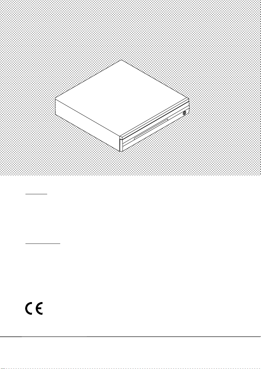
CASH
DRAWER
n USER’S GUIDE VER. A
NOTICE
The manufacturer of the POS cash drawer makes no representation or warranties, either
expressed or implied, by or with respect to anything in this manual, and shall not be
liable for any implied warranties of fitness for a particular purpose or for any indirect,
special or consequential damages. Information in this document is subject to change
without notice and does not represent a commitment on the part of the manufacturer.
FCC NOTICE
This equipment generates, uses, and can radiate radio frequency energy and if not
installed and used in accordance with the instructions manual, may cause interference to
radio communications. It has been tested and found to comply with the limits for a Class
A digital device pursuant to Subpart J of Part 15 of FCC Rules, which are designed to
provide reasonable protection against interference when operated in a commercial
environment. Operation of this equipment in a residential area is likely to cause
interference in which case the user at his own expense will be required to take whatever
measures may be required to correct the interference.
Models CR-3101/3201
CR-3102/3202
CR-3103/3203

TABLE OF CONTENTS
. .
INTERFACE DESCRIPTION . . . . . . . . . . . . . . . . . . .
FEATURES . . . . . . . . . . . . . . . . . . . . . . . . . . . . . . . . . . 1
CARTON CONTENTS . . . . . . . . . . . . . . . . . . . . . . .
SPECIFICATIONS . . . . . . . . . . . . . . . . . . . . . . . . . . . . 3
CONNECTOR PIN-OUT . . . . . . . . . . . . . . . . . . . . . . . 4
CONTROLLER BOARD JUMPER . . . . . . . . . . . . . . 6
DIAGRAMS . . . . . . . . . . . . . . . . . . . . . . . . . . . . . . . . . . 7
1
1
i

FEATURES
. Rugged design with reinforced heavy gauge steel construction.
. Large ball bearings riding on special guides for remarkably smooth drawer slide
. Contemporary style
. Input/Output expansion connectors.
. Advanced electronics that extend the MTBF (Mean Time Between Failure).
. Precision mechanical parts with tight tolerance to assure wobble-free drawer
movements.
. Check slot for non-cash or large-bill transaction.
. Three-position lock for maximum cash security.
. Optional interfaces include:
- Dedicated RS232C (CR-3101/3201)
- Non-dedicated RS232C (CR-3102/3202)
- Parallel (CR-3103/3203)
. Removable tray with a lock-on cover. Bill compartments and coin compartments
are adjustable. The tray cover TC3100 for CR-3101~3 and TC3200 for CR3201~3 are optional.
. Open-drawer indicator output
. Mutual convertability among CR-3101~3 and among CR-3201~3.
CARTON CONTENTS
1. Cash drawer preassembled
2. User’s manual
3. Key 2 pcs, there is a key serial no. sticker on the cash drawer bottom plate. If
user lost the key he/she can order the key according to this number.
4. Separator of bill compartment 4 pcs (for CR-3101~3) / 5pcs (for CR-3201~3),
separator of coin compartment 6 pcs.
5. Cable:
CCBLA-077-2 with one 9PF and one 25PF connector. (for CR3101/3102/3201/3202)
CCBLA-089 with one 25PM and one 25PF connector (for CR-3103/CR-3203).
6. Power adapter: Supplies 12VAC 1A.
INTERFACE DESCRIPTION
Model CR-3101/3201 with Dedicated Interface:
• Connect the drawer to the computer as shown in Fig 1. Connect the power
adapter output to the Power Input jack.
• Whenever the POS application software transmits data of any kind to the
computer COM1 (or COM2) port, the drawer will be opened. No other
RS232C data-receiving devices should be connected to the same serial port.
1

• For dedicated interface BIT 7 of S2 must be set to OFF and BIT 8 of S2 set
to ON. Please refer to Fig 3.
Model CR-3102/3202 with Non-Dedicated Interface:
• Connect the drawer to the computer as shown in Figure 1. Connect the
power adapter output to the Power Input jack.
• Whenever the POS application software transmits the pre-set security code
to the COM1 (or COM2) port, the drawer will be opened. The pre-set
security code was preset by the manufacturer at (07 Hex) and can be
changed as shown in Fig 3. Under normal operations, the selected pre-set
code should be a non-displayable ASCII character. For example, a
hexadecimal number between 01 to 1F. Note that other RS232C devices can
be connected to the same serial port, as long as this preset security code
makes no influence to the other RS232C device.
• For non-dedicated interface, BIT 7 of S2 must be set to ON and BIT 8 of S2
must be set to OFF. Please refer to Fig 3.
Model CR-3103/3203 with Parallel Interface:
• Connect the drawer to the computer as shown in Figure 2. Connect the
power adapter output to the Power Input jack.
• Whenever the POS application software transmits the pre-set security code
to the parallel LPT1 port, the drawer will be opened. The pre-set security
code was preset by the manufacturer at (07 Hex) and can be changed as
shown in Fig 3. Under normal operations, the selected pre-set code should
be non-displayable ASCII character. For example, a hexadecimal number
between 01 to 1F. Note that other parallel devices such as printer can be
connected to the same parallel port, as long as this preset security code
makes no influence to the other parallel devices.
Model CR-3101~3/3201~3 Keylock Operation:
: Permanent lock the drawer.
: Open the drawer by the key.
: Automatic open the drawer by or the
computer control.
2

SPECIFICATIONS
MECHANICAL: CR-3101~3 CR-3201~3
Weight 6.5 kgs 9 kgs
Height 9 cm 9.5 cm
Width 40 cm 50 cm
Depth 41.5 cm 42 cm
ELECTRICAL:
INPUT TO SOLENOID
Pulse Amplitude 12VDC to 24VDC
Pulse Width 200 milliseconds to 300 milliseconds
Pulse Duty Cycle 10% maximum
Peak Current 1 Ampere
POWER ADAPTER
Input Voltage 120VAC, +10% -20%
50 -60Hz
20W
Output Voltage 12VAC at 1A
SERIAL INPUT (CR-3101/3201, CR-3102/3202)
Data Format Standard RS232C
Protocol (see Figure3)
Security Code(CR-3102/3202) 1-255; 7*
Open-Drawer Indicator Open-collector, conducting between Pin9
(* denotes factory default setting)
No handshake
Baud rate:
150,300,600,1200,2400,4800,9600*,
19,200
Parity: none*, even, or odd
Data bits: 7 or 8*
and Pin11 of P3 when drawer opened
PARALLEL INPUT (CR-3103/3203)
Data Format Standard Centronics parallel interface
Security Code 1-255; factory preset value = 7
Open-Drawer Indicator Open-collector, conducting between Pin9
and Pin11 of P3 when drawer opened
3

CONNECTOR PIN-OUT (See Fig 4)
P1 (DB25M) - Parallel Input From Computer
1 - -Strobe
2 - Data 0
.
.
9 - Data 7
10 - -ACK
11 - Busy
12 - Paper End
13 - Select
14 - Auto Feed
15 - Error
16 - -Initialize Printer
17 - -Select Input
18 - NC
19 through 25 - Ground
P2 (DB25F) - Parallel Output to Printer
1 - -Strobe
2 - Data 0
.
.
9 - Data 7
10 - -ACK
11 - Busy
12 - Paper End
13 - Select
14 - Auto Feed
15 - Error
16 - -Initialize Printer
17 - -Select Input
18,21,25 - Printer-Connected detection
19,20,22,23,24 - Ground
4

P3 (DB25M) - Serial Input From Computer
2 - Receive data from computer
3 - Transmit data to computer
4 - RTS, Request To Send; from computer;(connected to 5)
5 - CTS, Clear To Send; to computer;(connected to 4)
6 - DSR, Data Set Ready; to computer;(connected to 8 & 20)
7 - Ground
8 - DCD, Data Carrier Detect; to computer;(connected to 6 & 20)
9 - Open-drawer indicator; collector of optical sensor (positive
end), conducting to pin 11 when drawer opened.
11 - Open-drawer indicator; emitter of optical sensor (negative
end), conducting to pin 9 when drawer opened.
Pin9 of P3
Pin11 of P3
18 - POS printer interface, pair with pin 25
20 - DTR, Data Terminal Ready; from computer; (connected to 6
& 8)
25 - POS printer interface, pair with pin 18
Note for Additional Features to RS-232C:
1. Open-drawer status of the drawer can be fed back to the
computer through the use of Pin9 and Pin11 as described above.
2. The simulation to CR-3100/CR-3200 can be achieved through
the use of Pin18 and Pin25 as described above. That is the Pin18
and Pin25 pair can be used as the input to solenoid in CR3100/CR-3200 without the need of the power adapter by
connecting this pair to POS printer output, then CR-3101~3/CR3201~3 will work the same way as CR-3100/CR-3200.
P4 (DB9F) - Pass-through Serial Output
2 - Transmit data to computer, connected to Pin3 of P3.
3 - Receive data from computer, connected to Pin2 of P3.
5 - Ground
(Pins 1,4,6,7,8,9 are connected to the corresponding pin in P5)
P5 (DB9M) - Pass-Through Serial Output
Same as P4
5

P6 (DB9M) - Serial Input from computer
1 - DCD (connected to pins 4 & 6)
2 - Receive data from computer, connected to Pin2 of P3.
3 - Transmit data to computer, connected to Pin3 of P3.
4 - DTR (connected to pins 1 & 6)
5 - Ground
6 - DSR (connected to pins 1 & 4)
7 - RTS (connected to pin 8)
8 - CTS (connected to pin7)
CONTROLLER BOARD JUMPERS (Located inside the drawer)
J1 - Connects to Input Power Jack for 12VAC @1A
JP1 - Not used
JP3 - Pin 1-2 to receive security code via Pin3 of P3, Pin3 of P6, Pin2 of P4 or
Pin2 of P5.
Pin 3-4* to receive security code via Pin2 of P3, Pin2 of P6, Pin3 of P4
or Pin3 of P5.
(*denotes factory default setting)
JP4 - Connects to solenoid, no polarity
JP5 - Connects to P3 for open-drawer indicator
1 collector, open-drawer indicator
2 emitter, open-drawer indicator
3, 4 ground
JP6 - Connects to optical interrupter
1 collector
2 cathode (ground)
3 emitter (ground)
4 anode
S1 - Set security code. Please refer to Figure 3.
S2 - Set RS232 protocol. Please refer to Figure 3.
S2 - BIT7 ON and BIT8 OFF for non-dedicated RS-232C.
S2 - BIT7 OFF and BIT8 ON for dedicated RS-232C.
6

7891011


Figure 5

Figure 6
12
 Loading...