

Page 1
Note: Rockler may not carry all products and/or sizes listed in this vendor's publication
RTD10000197AA
ESPAÑOL: PÁGINA 23
FRANÇAISE : PAGE 43
Instruction
manual
73999
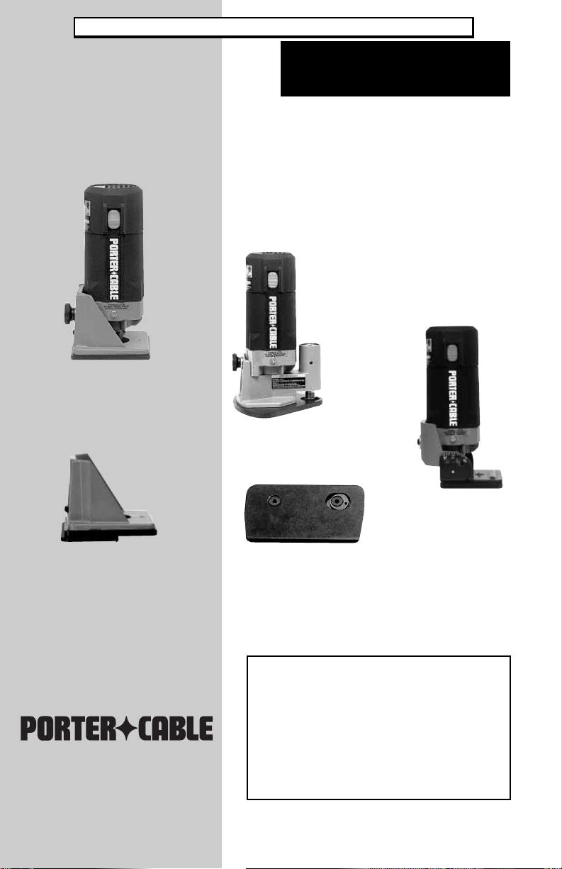
MODEL 7310
Trimmer
MODEL 7320
Base
Double Insulated
Laminate Trimmers
MODEL 7312
Offset Trimmer
MODEL 7319
Tilt Base Trimmer
Attachment
For 97311
To learn more about Porter-Cable
visit our website at:
http://www.porter-cable.com
Copyright © 2005 Porter-Cable
IMPORTANT!
Please make certain that the person who is
to use this equipment carefully reads and
understands these instructions before starting
operations.
The Model and Serial No. plate is located on the
main housing of the tool. Record these numbers in
the spaces below and retain for future reference.
®
Model No. __________________________________
T ype _______________________________________
Serial No. __________________________________
Part No. A13635 - 09-23-05 - Rev.A
Page 2

TABLE OF CONTENTS
IMPORTANT SAFETY INSTRUCTIONS. . . . . . . . . . . . . . . . . . . . . . . . . . 2
SAFETY GUIDELINES. . . . . . . . . . . . . . . . . . . . . . . . . . . . . . . . . . . . . . . . 3
GENERAL SAFETY RULES . . . . . . . . . . . . . . . . . . . . . . . . . . . . . . . . . . . 4
ADDITIONAL SPECIFIC SAFETY RULES . . . . . . . . . . . . . . . . . . . . . . . . 6
FUNCTIONAL DESCRIPTION . . . . . . . . . . . . . . . . . . . . . . . . . . . . . . . . . 8
CARTON CONTENTS . . . . . . . . . . . . . . . . . . . . . . . . . . . . . . . . . . . . . . . . 9
ASSEMBLY . . . . . . . . . . . . . . . . . . . . . . . . . . . . . . . . . . . . . . . . . . . . . . . . 9
OPERATION . . . . . . . . . . . . . . . . . . . . . . . . . . . . . . . . . . . . . . . . . . . . . . . 9
TROUBLESHOOTING . . . . . . . . . . . . . . . . . . . . . . . . . . . . . . . . . . . . . . 16
MAINTENANCE. . . . . . . . . . . . . . . . . . . . . . . . . . . . . . . . . . . . . . . . . . . . 20
SERVICE . . . . . . . . . . . . . . . . . . . . . . . . . . . . . . . . . . . . . . . . . . . . . . . . . 20
ACCESSORIES . . . . . . . . . . . . . . . . . . . . . . . . . . . . . . . . . . . . . . . . . . . . 21
WARRANTY. . . . . . . . . . . . . . . . . . . . . . . . . . . . . . . . . . . . . . . . . . . . . . . 22
ESPAÑOL. . . . . . . . . . . . . . . . . . . . . . . . . . . . . . . . . . . . . . . . . . . . . . . . . 23
FRANÇAISE. . . . . . . . . . . . . . . . . . . . . . . . . . . . . . . . . . . . . . . . . . . . . . . 43
IMPORTANT SAFETY INSTRUCTIONS
Read and understand all warnings and operating instructions
before using any tool or equipment. When using tools or equipment, basic
safety precautions should always be followed to reduce the risk of personal
injury. Improper operation, maintenance or modification of tools or equipment
could result in serious injury and property damage. There are certain applications
for which tools and equipment are designed. Porter-Cable strongly recommends
that this product NOT be modified and/or used for any application other than for
which it was designed.
If you have any questions relative to its application DO NOT use the product
until you have written Porter-Cable and we have advised you.
Online contact form at www.porter-cable.com
Postal Mail: Technical Service Manager
Porter-Cable
4825 Highway 45 North
Jackson, TN 38305
Information regarding the safe and proper operation of this tool is available from
the following sources:
Power Tool Institute
1300 Sumner Avenue, Cleveland, OH 44115-2851
www.powertoolinstitute.org
National Safety Council
1121 Spring Lake Drive, Itasca, IL 60143-3201
American National Standards Institute, 25 West 43rd Street, 4 floor, New
York, NY 10036 www.ansi.org ANSI 01.1Safety Requirements for
Woodworking Machines, and the U.S. Department of Labor regulations www.
SAVE THESE INSTRUCTIONS!
2
Page 3

SAFETY GUIDELINES - DEFINITIONS
It is important for you to read and understand this manual. The
information it contains relates to protecting YOUR SAFETY and
PREVENTING PROBLEMS. The symbols below are used to help
you recognize this information.
avoided, will result in death or serious injury.
avoided,could result in death or serious injury.
property damage.
indicates an imminently hazardous situation which, if not
indicates a potentially hazardous situation which, if not
indicates a potentially haz ard ous situation which, if not
avoided,may result in minor or mod erate injury.
used without the safety alert symbol indicates potentially
hazardous situation which, if not avoided, may result in
CALIFORNIA PROPOSITION 65
Some dust created by power sanding, sawing, grinding, drilling,
State of California) to cause cancer, birth defects or other reproductive harm. Some
examples of these chemicals are:
● lead from lead-based paints
● crystalline silica from bricks and cement and other masonry products
● arsenic and chromium from chemically-treated lumber
Your risk from these exposures varies, depending on how often you do this type
of work. To reduce your exposure to these chemicals: work in a well ventilated
area, and work with approved safety equipment, al ways wear NIOSH/OSHA
approved, properly fit ting face mask or res pirator when us ing such tools.
and other construction activities contains chemicals known (to the
3
Page 4

GENERAL SAFETY RULES
instructions listed below may result in electric shock, fire and/or
serious injury. The term "power tool" in all of the warnings listed
below refers to your mains-operated (corded) power tool or
battery-operated (cordless) power tool.
SAVE THESE INSTRUCTIONS
1) Work area safety
a) Keep work area clean and well lit. Cluttered or dark areas invite
b) Do not operate power tools in explosive atmospheres, such as
c) Keep children and bystanders away while operating a power tool.
Distractions can cause you to lose control.
2) Electrical safety
a) Power tool plugs must match the outlet. Never modify the plug in
b) Avoid body contact with earthed or grounded surfaces such as
c) Do not expose power tools to rain or wet conditions. Water entering
d) Do not abuse the cord. Never use the cord for carrying, pulling or
e) When operating a power tool outdoors, use an extension cord
3) Personal safety
a) Stay alert, watch what you are doing and use common sense
b) Use safety equipment. Always wear eye protection. Safety
c) Avoid accidental starting. Ensure the switch is in the off-position
d) Remove any adjusting key or wrench before turning the power tool
Read all instructions. Failure to follow all
accidents.
in the presence of flammable liquids, gases or dust. Power tools
create sparks which may ignite the dust or fumes.
any way. Do not use any adapter plugs with earthed (grounded)
power tools. Unmodified plugs and matching outlets will reduce risk
of electric shock.
pipes, radiators, ranges and refrigerators. There is an increased risk
of electric shock if your body is earthed or grounded.
a power tool will increase the risk of electric shock.
unplugging the power tool. Keep cord away from heat, oil, sharp
edges or moving parts. Damaged or entangled cords increase the
risk of electric shock.
suitable for outdoor use. Use of a cord suitable for outdoor use
reduces the risk of electric shock.
when operating a power tool. Do not use a power tool while you
are tired or under the influence of drugs, alcohol or medication.
A moment of inattention while operating power tools may result in
serious personal injury.
equipment such as dust mask, non-skid safety shoes, hard hat, or
hearing protection used for appropriate conditions will reduce personal
injuries.
before plugging in. Carrying power tools with your finger on the switch
or plugging in power tools that have the switch on invites accidents.
4
Page 5

GENERAL SAFETY RULES
on. A wrench or a key left attached to a rotating part of the power tool
may result in personal injury.
e) Do not overreach. Keep proper footing and balance at all times.
This enables better control of the power tool in unexpected situations.
f) Dress properly. Do not wear loose clothing or jewelry. Keep your
hair, clothing and gloves away from moving parts. Loose
clothes, jewelry or long hair can be caught in moving parts.
g) If devices are provided for the connection of dust extraction and
collection facilities, ensure these are connected and properly
used. Use of these devices can reduce dust-related hazards.
4) Power tool use and care
a) Do not force the power tool. Use the correct power tool for your
application. The correct power tool will do the job better and safer at
the rate for which it was designed.
b) Do not use the power tool if the switch does not turn it on and off.
Any power tool that cannot be controlled with the switch is dangerous
and must be repaired.
c) Disconnect the plug from the power source before making any
adjustments, changing accessories, or storing power tools. Such
preventive safety measures reduce the risk of starting the power tool
accidentally.
d) Store idle power tools out of the reach of children and do not
allow persons unfamiliar with the power tool or these instructions
to operate the power tool. Power tools are dangerous in the hands of
untrained users.
e) Maintain power tools. Check for misalignment or binding of
moving parts, breakage of parts and any other condition that may
affect the power tools operation. If damaged, have the power tool
repaired before use. Many accidents are caused by poorly maintained
power tools.
f) Keep cutting tools sharp and clean. Properly maintained cutting
tools with sharp cutting edges are less likely to bind and are easier to
control.
g) Use the power tool, accessories and tool bits etc., in accordance
with these instructions and in the manner intended for the
particular type of power tool, taking into account the working
conditions and the work to be performed. Use of the power tool for
operations different from those intended could result in a hazardous
situation.
5) Service
a) Have your power tool serviced by a qualified repair person using
only identical replacement parts. This will ensure that the safety of
the power tool is maintained.
continued
5
Page 6

ADDITIONAL SPECIFIC SAFETY RULES
1. HOLD POWER TOOLS BY INSULATED GRIPPING SURFACES WHEN
PERFORMING AN OPERATION WHERE THE CUTTING TOOL MAY
CONTACT HIDDEN WIRING OR ITS OWN CORD. Contact with a "live"
wire will make exposed metal parts of the tool "live" and shock the operator.
2. USE CLAMPS OR OTHER PRACTICAL WAY TO SECURE AND
SUPPORT THE WORKPIECE TO A STABLE PLATFORM. Holding the
work by hand or against your body is unstable and may lead to loss of
control.
3. DISCONNECT TOOL FROM POWER SOURCE before making
adjustments or changing bits.
4. TIGHTEN COLLET NUT securely to prevent the bit from slipping.
5. USE A CLAMP or some other device to hold the workpiece rigidly in position.
and clear the path of the tool of obstructions.
6. CHECK TO SEE THAT THE CORD will not “hang up” during trimming
operation.
7. CLEAR THE TRIMMER BIT AREA before starting motor.
8. MAINTAIN FIRM GRIP on trimmer to resist starting torque.
9. KEEP HANDS CLEAR OF CUTTER when motor is running to prevent
personal injury.
10. KEEP CUTTING PRESSURE CONSTANT. Do not overload motor.
11. LET THE MOTOR COME TO A COMPLETE STOP before putting the tool
down.
12. NEVER TOUCH router bits after use. They may be extr emely hot.
13. NEVER TIGHTEN COLLET NUT without a bit.
14. DO NOT USE LAMINATE TRIMMER MOTOR WITHOUT THE LAMINATE
TRIMMER BASE INSTALLED. Loss of control could result, causing
personal injury or damage to work.
15. WEAR EYE AND HEARING PROTECTION. ALWAYS USE SAFETY
GLASSES. Everyday eyeglasses are NOT safety glasses. USE CERTIFIED
SAFETY EQUIPMENT. Eye protection equipment should comply with ANSI
Z87.1 standards. Hearing equipment should comply with ANSI S3.19
standards.
16.
DUST OR OTHER AIRBORNE PARTICLES, INCLUDING WOOD DUST,
CRYSTALLINE SILICA DUST AND ASBESTOS DUST. Direct particles
away from face and body. Always operate tool in well ventilated area and
provide for proper dust removal. Use dust collection system wherever
possible. Exposure to the dust may cause serious and permanent
respiratory or other injury, including silicosis (a serious lung disease),
cancer, and death. Avoid breathing the dust, and avoid prolonged contact
with dust. Allowing dust to get into your mouth or eyes, or lay on your skin
may promote absorption of harmful material. Always use properly fitting
NIOSH/OSHA approved respiratory protection appropriate for the dust
exposure, and wash exposed areas with soap and water.
USE OF THIS TOOL CAN GENERATE AND DISBURSE
6
Page 7

SYMBOL DEFINITION
V ........................................ volts
A ........................................ amperes
Hz ...................................... hertz
W ....................................... watts
kW ..................................... kilowatts
F ........................................ farads
µF ...................................... microfarads
l .......................................... litres
g ........................................ grams
kg....................................... kilograms
bar ..................................... bars
Pa ...................................... pascals
h ........................................ hours
min..................................... minutes
s ......................................... seconds
n
0 .......................................
.../min or …min
1
..............
-
or d.c. .................... direct current
or a.c. ....................... alternating current
2
............................ two-phase alternating current
2N ........................... two-phase alternating current with neutral
3
.............................. three-phase alternating current
3N ............................ three-phase alternating current with neutral
.............................. rated current of the appropriate fuse-link in amperes
................................. time-lag miniature fuse-link where X is the symbol for
................................... protective earth
no-load speed
Revolutions or reciprocations per minute
the time/current characteristic, as given in IEC 60127
.................................... class II tool
IPXX ................................... IP symbol
MOTOR
Many Porter-Cable tools will operate on either D.C., or single phase 25 to 60
cycle A.C. current and voltage within plus or minus 5 percent of that shown on
the specification plate on the tool. Several models, however, are designed for
A.C. current only. Refer to the specification plate on your tool for proper voltage
and current rating.
Do not operate your tool on a current on which the voltage is
not within correct limits. Do not operate tools rated A.C. only
on D.C. current. To do so may seriously damage the tool.
7
Page 8

EXTENSION CORD SELECTION
If an extension cord is used, make sure the conductor size is large enough to
prevent excessive voltage drop which will cause loss of power and possible
motor damage. A table of recommended extension cord sizes will be found in
this section. This table is based on limiting line voltage drop to 5 volts (10 volts
for 230 volts) at 150% of rated amperes.
If an extension cord is to be used outdoors it must be marked with the suffix WA or W following the cord type designation. For example – SJTW-A to indicate it
is acceptable for outdoor use.
RECOMMENDED EXTENSION CORD SIZES FOR USE WITH PORTABLE ELECTRIC TOOLS
115V 25 Ft. 50 Ft. 100 Ft. 150 Ft. 200 Ft. 250 Ft. 300 Ft. 400 Ft. 500 Ft.
230V 50 Ft. 100 Ft. 200 Ft. 300 Ft. 400 Ft. 500 Ft. 600 Ft. 800 Ft. 1000 Ft.
0-2 18 18 18 16 16 14 14 12 12
2-3 18 18 16 14 14 12 12 10 10
3-4 18 18 16 14 12 12 10 10 8
4-5 18 18 14 12 12 10 10 8 8
5-6 18 16 14 12 10 10 8 8 6
6-8 18 16 12 10 10 8 6 6 6
8-10 18 14 12 10 8 8 6 6 4
10-12 16 14 10 8 8 6 6 4 4
12-14 16 12 10 8 6 6 6 4 2
14-16 16 12 10 8 6 6 4 4 2
Nameplate Ampere Rating
16-18 14 12 8 8 6 4 4 2 2
18-20 14 12 8 6 6 4 4 2 2
Length of Cord in Feet
FUNCTIONAL DESCRIPTION
FOREWORD
Porter-Cable Laminate Trimmers are designed for the flush and bevel
trimming of laminated plastics, phenolics, and other similar materials that
have a bonding agent too hard to be trimmed with ordinary tools.
The Tilt-Base model allows trimming into corners inaccessible to standard
trimmers. This model also allows the trimming of laminated surfaces joining
at angles of 45° to 90°. This feature eliminates the need for hand-trimming
in many applications.
The Off-Set Base Trimmer is designed for trimming into the corner of a back
splash and for trimming narrow ledges.
The Underscribe Base is designed for making accurate “butt” joints in
laminated plastics, phenolics and other similar materials. The Underscribe
Base is used with the Model 7301 Trimmer Motor and the 43109 Trim Bit.
SELECTING THE BIT
These trimmers are equipped with a 1/4" diameter collet to accept laminate
trimming bits having 1/4" diameter shanks. Bits are available as an
accessory .
8
Page 9
CARTON CONTENTS
1. Trimmer motor
2. Trimmer base (or bases, if a kit is purchased)
3. Wrench (or wrenches, if a kit is purchased)
ASSEMBLY
NOTE: This tool is shipped completely assembled. No assembly time or
tools are required.
OPERATION
MODEL 7301 MOTOR UNIT
All laminate trimmers in this manual use the Model 7301 Motor Unit.
TO ST ART AND STOP THE MOTOR
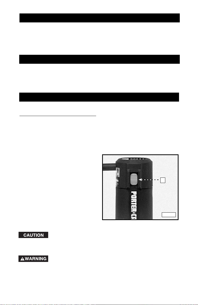
The "ON/OFF" switch (A) Fig. 1
is located on the side of the unit,
close to the top. To start the
trimmer, move the switch down
to the "ON" position. To stop the
trimmer, move the switch up to the
"OFF" position.
Prior to starting the tool, make
sure that the switch is in the "OFF"
position and that the power circuit
voltage is the same as that shown
on the specification plate of the
trimmer.
A
Fig. 1
Grasp trimmer firmly to resist starting torque and make sure
bit is clear of workpiece and foreign objects.
To avoid personal injury or damage to finished work always
allow the motor to come to a COMPLETE STOP before
setting trimmer down.
9
Page 10
TO INSTALL THE BIT
DISCONNECT THE TOOL FROM THE POWER SOURCE.
1. On Models 7310 and 7319, you can install bits either with the motor unit
attached or removed.
NOTE: See the instructions (Model 7312) for installing the bit in the OFFSET
trimmer . See instructions (Model 7320) for installing the bit in the UNDERSCRIBE
trimmer.
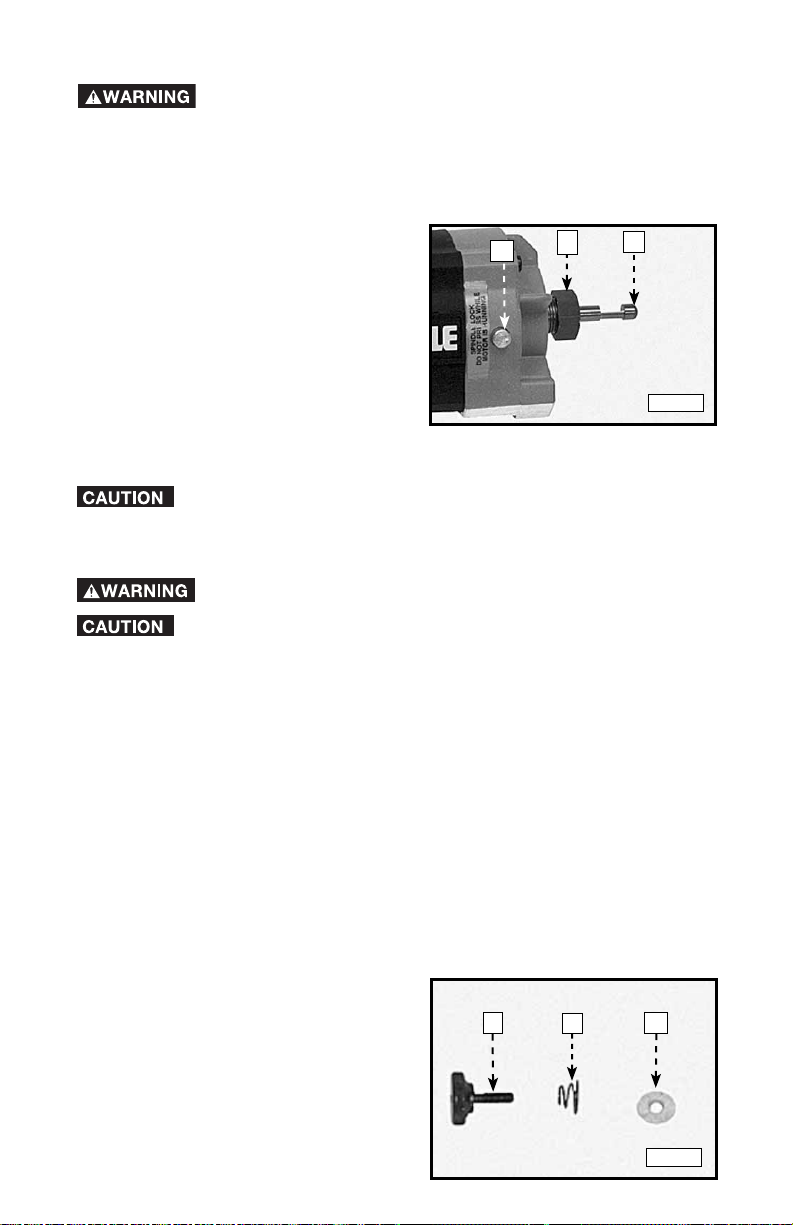
2. Clean and insert the shank of the
bit (C) Fig. 2 into the collet until the
end of the shank bottoms. Then
withdraw the bit approximately
1/16".
3. Depress the spindle lock (A) Fig.
2 and rotate the collet nut (B)
clockwise by hand until the lock
engages the hole in the motor
spindle.
4. While holding the spindle lock, use
the provided wrench to tighten the collet nut (clockwise) securely.
To prevent damage to the collet, do not tighten the collet without a
bit inserted.
A
B
C
Fig. 2
TO REMOVE THE BIT
DISCONNECT THE TOOL FROM THE POWER SOURCE.
Do not touch the trimmer bits immediately after use. They can get
very hot.
1. On Models 7310 and 7319, you can remove bits either with the motor unit
attached or removed.
NOTE: See the instructions (Model 7312) for installing the bit in the OFFSET
trimmer.
2. Depress the spindle lock and rotate the collet nut counter-clockwise by
hand until the lock engages the hole in the motor spindle.
3. While holding the spindle lock engaged, loosen the collet nut by turning it
counter-clockwise with the provided wrench.
4. If the bit is tight on the collet, tap the collet nut with a wrench to release the
bit.
MODEL 7310 TRIMMER ASSEMBLY
The Model 7310 Trimmer comes completely assembled from the factory. The
base is attached to (or removed from) the motor with a base locking screw (Fig.
3).
NOTE: The locking screw (A) Fig. 3
utilizes a spring (B) Fig. 3 and a flat
washer (C). Position the spring (B) with
its small end against the head of the
screw (A). Attach the washer (C) after
the spring.
10
A
B
C
Fig. 3
Page 11

ADJUSTING THE DEPTH OF CUT
1. Loosen the base-locking screw (A)
Fig. 4) approximately 1/4 turn.
2. Turn the depth-adjusting wheel (B)
Fig. 4 to reduce or increase the
depth of cut.
3. Tighten the base-locking screw
securely. Make a test cut in scrap
material to check the depth of cut.
4. Repeat steps 1 through 3 until the
desired depth of cut is achieved.
A
B
Fig. 4
ADJUSTING THE SUB-BASE ALIGNMENT
Applications using a template guide require the bit to be centered within the
guide, and the center hole in the sub-base to be in line with the collet of the
motor unit. Your model has an adjustable sub-base. To adjust:
1. Install the 42054 Template Guide (available as an accessory) on the sub-base and
tighten securely .
2. Loosen the sub-base mounting screws just enough to allow the sub-base to move
on the base.
3. Install a straight 1/4" diameter bit in the collet of the motor unit and tighten securely .
4. Attach the motor unit to the base. Align the hole in the template guide with the bit
and adjust the depth of cut so that the bit extends through the template guide.
Tighten the motor unit in the base.
5. Tighten the sub-base mounting screws securely .
THE OPTIONAL 73100 EDGE GUIDE KIT
The optional Model 73100 Edge Guide Kit is available for use with the Model
7310 trimmer. This kit is designed for use with non-piloted bits on curved or
straight applications. Non-piloted bits can produce a 90° straight cut, a 10°
bevel cut, or a 22° bevel cut. The kit (Fig. 5) contains:
A. Base and roller guide - for flush or bevel trimming
B. Edge guide – for flush trimming
C. Edge guide – for bevel trimming
D. Straight edge guide – for straight trimming
E. Guide setting gauge
F. Mounting screws
G. Wrench
A B C D E F
11
Fig. 5
G
Page 12
A TT ACHING AND ADJUSTING THE BASE AND THE ROLLER GUIDE
1.
Remove the power unit from the base unit (see “TO INST ALL BIT”).
2. Install the bit.
The base and roller guide (A) Fig. 5 is assembled at the factory. To install,
3.
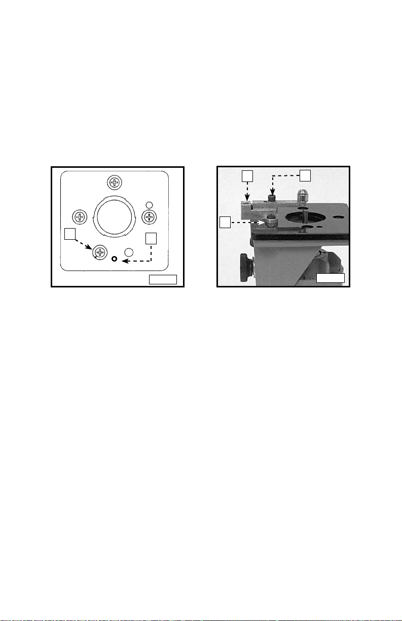
remove a sub-base mounting screw (A) Fig. 6 and insert the alignment pin (in
the guide base) into the hole (C) in the bottom of the trimmer sub-base. Fasten
with two mounting screws (F) Fig. 5 and (C) Fig. 7. Hand tighten for further
adjustment.
4. Install the bit (See “TO INSTALL THE BIT.”). Then, install the motor to base
and adjust the depth of cut (See “ADJUSTING DEPTH OF CUT”).
5. Align the roller guide with the bit by loosening the locking screw (A) Fig. 7 and
turning the adjusting screw (B) with the provided hex wrench until the guide is
in the desired location.
B
A
C
A
C
Fig. 6
Fig. 7
FLUSH TRIMMING
1. Attach the base and guide to the trimmer as outlined in "ATTACHING AND
ADJUSTING THE BASE AND ROLLER".
2. Remove the roller guide and replace it with the flush trimming guide (B) Fig.
4. Identify this guide by the molded letter “F”. Make sure that the stud on the
end of this guide faces the trimmer base.
3. Install the guide setting gauge (E) Fig. 4 in the trimmer collet (see "TO
INSTALL THE BIT"). Install the trimmer motor to the base. Adjust the guide
so that hole in the end of the gauge is positioned over the guide stud.
4. Remove the guide setting gauge from the trimmer and install a flush
trimming bit.
5. Adjust the depth of cut so that the straight portion of the bit extends below
the trimmer base at least the thickness of the workpiece.
6. Make a trial cut on scrap material.
BEVEL TRIMMING
1. Follow Steps 1 through 5 under "FLUSH TRIMMING", except install the
bevel trimming guide (C) Fig. 4. This guide is identified by the molded letter
“B”.
2. Adjust the depth of cut so that only the bevel portion of the bit extends
below the trimmer base at least the thickness of the material to be trimmed.
3. Make a trial cut on scrap material to check alignment.
12
Page 13
USING STRAIGHT EDGE GUIDE
You can use the straight edge guide (D) Fig. 5 with either bit for trimming straight
edges.
Attach it to the guide base and adjust similar to the other guides.
MODEL 7319 TILT BASE TRIMMER ASSEMBLY
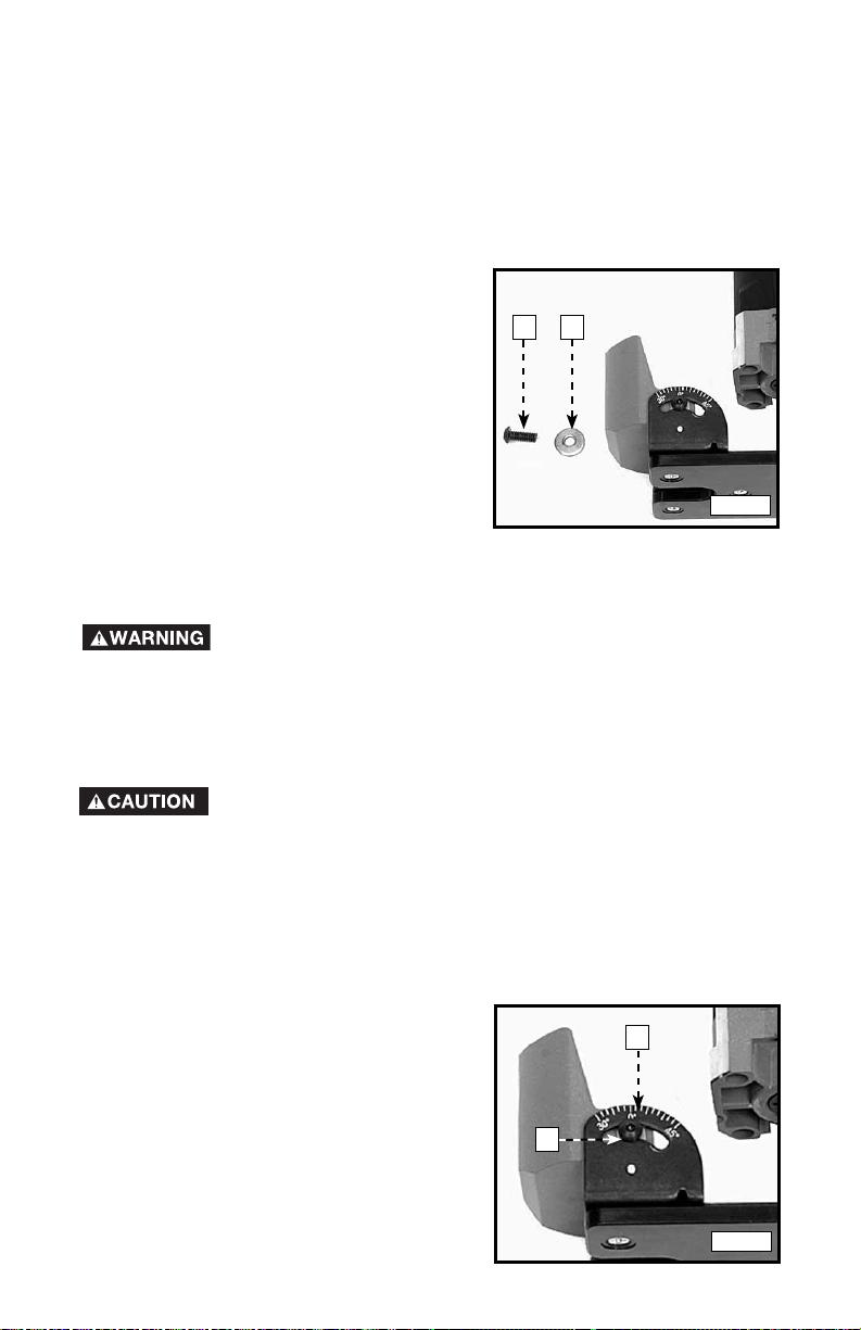
Model 7319 Tilt Base Trimmer is completely
attached at the factory. You can remove
the base from the Model 7301 motor with a
base locking screw (A) Fig. 8.
NOTE: A flat washer (B) Fig. 8 is on the
locking screw.
Model 7319 Tilt Base is designed for use
with 43216PC flush trim bit for trimming into
corners. You may also use it with other “self
pilot” trim bits for conventional trimming at
90° setting.
ADJUSTING THE DEPTH OF CUT
DISCONNECT THE TOOL FROM THE POWER SOURCE!
Loosen the base locking screw and move the motor unit up or down to decrease
or increase the depth-of-cut.
You may have to slightly withdraw some bits in the collet to obtain a maximum
depth of cut.
When you withdraw a bit, be certain that at least 1/2" of the
bit shank is engaged in the collet. Do not use bits that result in
having less than 1/2" of the bit shank engaged in the collet. To do so may cause
poor gripping of the collet, resulting in a loose bit. If the bit comes out of the
collet, it could cause damage to the workpiece and/or personal injury.
A B
Fig. 8
ADJUSTING THE TILT
1. Loosen two tilt locking screws (C)
Fig. 9 (one on each side of base)
using the provided wrench.
2. Match the base-aligning index mark
(D) Fig. 9 with the desired angle and
tighten securely.
3. Make a trial cut on scrap material to
check the alignment.
D
C
Fig. 9
13
Page 14
MODEL 7312 OFFSET TRIMMER ASSEMBLY
Your Model 7312 Offset Trimmer was assembled at the factory. However, if you
choose to attach an auxiliary base, use the following instructions:
DISCONNECT THE TOOL FROM THE POWER SOURCE!
1. Remove the collet nut and collet from the motor unit.
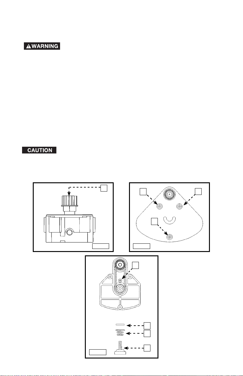
2. Attach the drive pulley (A) Fig. 10 to the motor spindle. Tighten securely.
3. Use a phillips screwdriver to remove the three sub-base mounting screws
(A) Fig. 11 from the base. Remove the sub-base.
4. Position the base on the motor and the drive pulley assembly (from
STEP 2). Be sure that the motor drive pulley engages the drive belt inside
the base housing.
5. Secure the motor to the base (Fig. 9) with the thumbscrew (A), spring (B),
and washer (C).
6. Use the Phillips screwdriver to install a #6-32 x 3/8" screw (D) as shown in
Fig. 12. Tighten securely.
7. Clean the collet nut and collet, and attach to the spindle in the offset base.
Hand tighten for further adjustment.
to damage the collet.
8. Position the sub-base to the base housing and secure with the three screws
that were removed in STEP 3.
Tightening the collet nut without a bit installed in the collet is likely
Fig. 10
Fig. 12
A
A
A
A
Fig. 11
D
C
B
A
14
Page 15
TO INSTALL & REMOVE THE BIT
DISCONNECT THE TOOL FROM THE POWER SOURCE!
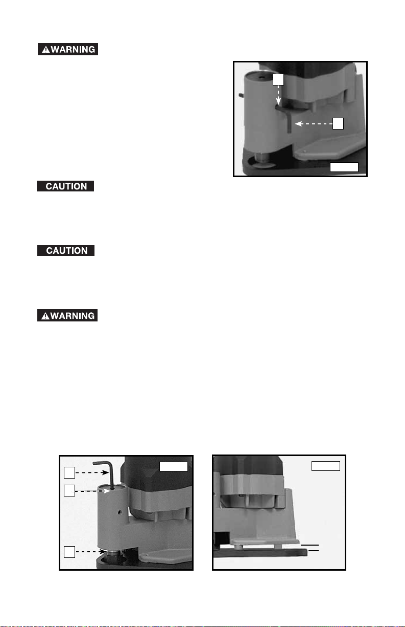
1. Insert the long portion of the hex wrench
(A) Fig. 13 through the spindle lock hole
B
(B) Fig. 13, so that the wrench protrudes
from both sides of the base housing.
Rotate the spindle by hand to align the
hole in the spindle with the holes in the
housing.
A
2. Clean and insert the bit shank into the
collet. Tighten the collet nut securely
with the collet wrench.
Fig. 13
To prevent damage to the drive belt, never tighten or loosen the
collet nut with the spindle lock engaged.
3. To remove the bit, reverse the procedure. If the bit will not remove easily,
lightly tap the bit shank with a wrench.
To prevent damage to the collet, never tighten the collet without a
bit inserted.
ADJUSTING THE DEPTH OF CUT
DISCONNECT THE TOOL FROM THE POWER SOURCE!
1. Loosen the bit in the collet (See "TO INSTALL & REMOVE THE BIT").
2. Place the hex wrench (A) Fig. 14 in the depth-adjusting screw (B).
3. Hold the spindle (C) Fig. 14 with your fingers. Apply light upward pressure on
the bit to maintain contact between the bit shank and the adjusting screw.
Turn the hex wrench counter-clockwise to increase exposure and clockwise
to decrease exposure.
4. To turn the sub-base over for long-shank bits:
A. Remove three sub-base mounting screws.
B. Turn sub-base over and re-attach using screws removed in STEP A.
A
Fig. 14
SUB-BASE
INVERTED
Fig. 15
B
3
C
15
/16"
Page 16

OPERATION
DISCONNECT THE TOOL FROM THE POWER SOURCE.
Always wear safety glasses while operating a laminate trimmer.
1. Allow your workpiece to overhang the base material by at least 1/8".
2. Firmly grasp the motor housing, being sure switch is in the “OFF” position.
3. Ensure that the bit is clear of foreign objects and that the cord will not “hang
up” on any obstructions.
4. Hold the workpiece firmly in place. Use clamps when necessary.
5. Plug in the power supply cord. Be alert to resist the starting torque of the
motor. Turn motor “ON”.
6. Allow the motor to reach “full speed”. Place the base of the trimmer on the
surface of the workpiece. Feed the trimmer into the work until the bit pilot
contacts the base material. When guiding on a previously laminated surface,
always wax or lubricate the area where the guide will ride.
NOTE: While operating the trimmer with
the tilt base at any tilt setting other than
“0” degrees, keep the long side of the base
perpendicular to the piloting surface to
prevent possible work spoilage.
7. Feed from left to right with a smooth
steady motion (See Fig. 16).
8. When the operation is complete, tur n
the switch “OFF”. Allow the motor to
come to a complete stop before laying
the trimmer down.
Fig. 16
UNDERSCRIBE 7320 TRIMMER ASSEMBLY
To attach the Underscribe Trimmer Base to the Model 7301 Trimmer Motor:
NOTE: The 43109 Trim Bit must be installed into the Trimmer Motor before
attaching the motor to the Underscribe Base.
DISCONNECT THE TOOL FROM THE POWER SOURCE!
1. Clean and insert the shank of the bit (A)
Fig. 17, into the collet until the end of
the shank bottoms. Then pull the bit out
approximately 1/8".
2. Depress the spindle lock (B) Fig. 17, and
rotate the collet nut (C) clockwise by
hand until the lock engages the hole in
the motor spindle.
3. While holding the spindle lock engaged,
tighten the collet nut securely by turning
it clockwise, using the provided wrench.
To prevent damage to the collet, never tighten the collet without a bit
inserted.
16
Fig. 17
B
A
C
Page 17

4. Secure the base (A) Fig. 19 on the motor (B) using the locking screw (E),
spring (D) and washer (C) Fig. 18.
NOTE: Orient the spring with the small end against the head of the locking
screw.
5. Align the two holes in the underscribe attachment (G) Fig. 18 with the two
holes in the base (A).
6. Attach the underscribe attachment (G) Fig. 19 to the base (A) with two
screws and an eccentric washer.
B
E
D
C
A
G
Fig. 18
Fig. 19
TYPICAL APPLICATIONS
TRIMMING
VERTICAL BACKSPLASH OF INSTALLED CORNER BACKSPLASH TO WALL
APPLICATION – Trimming front edge of
3
/4" vertical backsplash. This is an opera-
tion standard trimmers with round or
square bases are unable to do without
the use of a special bit.
Self-piloted bit
guides trimmer for
one-pass trimming
every time.
OPERATION – Trimming
with the new Porter-Cable Offset Laminate
Trimmer fitted with a solid carbide selfpiloted bit.
3
/4" IN-AND-OUT TRIMMING SCRIBING OF
APPLICATION – Accurately scribing the back
side of a preassembled panel or post-formed
backsplash. Once the lip is accurately scribed,
the trimmed portion is then pushed against the
wall and mated exactly.
Self-piloted bit
follows every
trimmer movement
to create exact
reproduction of wall
surface in one pass!
OPERATION – The guide assembly must
be removed. Using the self-piloted bit,
the Porter-Cable Offset Trimmer scribes
accurately to the wall surface.
Maintain
from wall for scribing.
Triangular base
enables trimming with
backsplash in place.
3
/4" backsplash
APPLICATION – Trimming into and
out of installed backsplash corner
with little or no hand trimming
required.
Triangular base
enables complete
corner trimming
with backsplash
in place.
OPERATION – The new Porter-Cable
Offset Trimmer will trim into and out
of 90° corners with ease using selfpiloted bit.
Front edge
of trimmer
3
/4" separation
is guided
against
wall.
17
Page 18

Trims up to
vertical surfaces.
ADJUSTING THE BIT EXPOSURE
DISCONNECT THE TOOL FROM THE POWER SOURCE.
Trims odd angled
corners less than
or greater than
90°.
1. Loosen the base locking screw (E)
Fig. 20 approximately 1/4 turn.
2. Tur n the depth-adjusting wheel (D)
Fig. 20 counter-clockwise (looking
at top of wheel) to lower the bit
until it touches the guide plate.
3. Firmly tighten the locking screw (E).
D
Fig. 20
ADJUSTING GUIDE PLATE
The Underscribe Trimmer Base is equipped with an adjustable guide plate (Fig.
21). Adjust the guide plate by rotating the eccentric, using the special wrench
that is supplied with the Trimmer Base. To adjust the guide:
1. Make a trial cut using scrap material and check the fit.
DISCONNECT THE TOOL FROM THE POWER SOURCE.
E
2. Turn the eccentric to correct fit.
NOTE: If the joint is too loose (with
a crack between the two pieces of
laminate), turn the eccentric clockwise.
If joint to too tight so that the laminate
will not snap into place, turn the
eccentric counter-clockwise.
3. Repeat Steps 1 through 3 as required
to achieve a good fit.
Fig. 21
USING THE UNDERSCRIBE TRIMMER
The bottom plate of the Underscribe Trimmer has a guide lip (Fig. 22). This guide
lip is moved along an installed piece of laminate as the trimmer bit cuts the
mating piece of laminate.
18
Page 19

The “butt” joint is commonly used in the construction of face frames. To install a
laminate covering on a face frame:
Always wear safety glasses while operating a laminate trimmer.
A Trimmer Base
B Sub-Base
C Installed laminate
D Guide Lip
A
B
E
F
D
E Bit
F Laminate
C
Fig. 22
1. Cut the pieces of laminate covering to rough size. Apply contact cement to
the face frame and the laminate pieces in the normal manner.
NOTE: Cut the rail covering approximately 1" longer than the rail (to allow
material for trimming).
2. Apply the laminate to all stiles.
3. Position the laminate to a rail with at
Fig. 23
least 1/4", and no more than 3/4",
overlapping each stile (see Fig. 23).
Use a roller to secure the center
section of the laminate to the rail.
Leave at least 4" of the laminate loose,
at both ends of the rail (Do not roll it
down).
4. Securely clamp the face frame
assembly to the worktable to prevent movement during the trimming
operation.
5. Position the underscribe trimmer onto the face frame so that the top (see
Fig. 24), is against the edge of the stile.
NOTE: The trimmer should be to the right of the rail, so that the cutting action
will move from right to left (see Fig. 24).
NOTE: The finished cut is illustrated in Fig.25.
Fig. 24 Fig. 25
19
Page 20

6. Verify that the bit is clear of foreign objects and that the cord will not get
caught on any obstructions.
7. Grasp the motor firmly to resist starting torque and move the switch button
to the "ON" position.
8. Allow the motor to reach full-speed. Feed the trimmer from right to left with
a smooth steady motion.
NOTE: The tapered edge of the underscribe base will slide underneath the rail
covering, lifting the laminate into the cutter.
9. After completing the cut, move the switch button to the "OFF" position
and allow the motor to come to a complete stop before putting the trimmer
down.
10. Press the rail end into position and roll down.
11. Repeat this process as necessary to complete the face frame.
TROUBLESHOOTING
For assistance with your tool, visit our website at www.porter-cable.com for a
list of service centers, or call the Porter-Cable Customer Care Center at 1-800223-7278.
MAINTENANCE
KEEP TOOL CLEAN
Periodically blow out all air passages with dry compressed air. All plastic parts
should be cleaned with a soft damp cloth. NEVER use solvents to clean plastic
parts. They could possibly dissolve or otherwise damage the material.
Wear ANSI Z87.1 safety glasses while using compressed air.
FAILURE TO START
Should your tool fail to start, check to make sure the prongs on the cord plug are
making good contact in the outlet. Also, check for blown fuses or open circuit
breakers in the line.
LUBRICATION
This tool has been lubricated with a sufficient amount of high grade lubricant for
the life of the unit under normal operating conditions. No further lubrication is
necessary.
BRUSH INSPECTION (If applicable)
For your continued safety and electrical protection, brush inspection and
replacement on this tool should ONLY be performed by an AUTHORIZED
PORTER-CABLE SERVICE STATION or a PORTER-CABLE
FACTORY SERVICE CENTER.
At approximately 100 hours of use, take or send your tool to your nearest
authorized Porter-Cable Service Station to be thoroughly cleaned and inspected.
Have worn parts replaced and lubricated with fresh lubricant. Have new brushes
installed, and test the tool for performance.
Any loss of power before the above maintenance check may indicate the need
for immediate servicing of your tool. DO NOT CONTINUE TO OPERATE TOOL
UNDER THIS CONDITION. If proper operating voltage is present, return your
tool to the service station for immediate service.
20
• DELTA
Page 21

SERVICE
REPLACEMENT PARTS
Use only identical replacement parts. For a parts list or to order parts, visit our website
at servicenet.porter-cable.com. You can also order parts from your nearest factoryowned branch, or by calling our Customer Care Center at 1-800-223-7278 to receive
personalized support from highly-trained technicians.
SERVICE AND REP AIRS
All quality tools will eventually require servicing and/or replacement of parts. For
information about Porter-Cable, its factory-owned branches, or an Authorized Warranty
Service Center, visit our website at www.porter-cable. com or call our Customer Care
Center at 1-800-223-7278. All repairs made by our service centers are fully guaranteed
against defective material and workmanship. We cannot guarantee repairs made or
attempted by others.
You can also write to us for information at PORTER-CABLE, 4825 Highway 45 North,
Jackson, Tennessee 38305 - Attention: Product Service. Be sure to include all of the
information shown on the nameplate of your tool (model number , type, serial number, etc.).
ACCESSORIES
A complete line of accessories is available from your Porter-Cable•Delta
Supplier, Porter-Cable
Authorized Service Stations. Please visit our Web Site www.porter-cable.
com for a catalog or for the name of your nearest supplier.
•Delta Factory Service Centers, and Porter-Cable
Porter-Cable
•Delta have not been tested with this product, use of
such accessories could be hazardous. For safest operation, only
Since accessories other than those offered by
Porter-Cable
•Delta recommended accessories should be used
with this product.
21
Page 22

WARRANTY
To register your tool for warranty service visit our website at www.porter-cable.
com.
PORTER-CABLE LIMITED
ONE YEAR WARRANTY
Porter-Cable warrants its Professional Power Tools for a period of one year from the date of original
purchase. We will repair or replace at our option, any part or parts of the product and accessories
covered under this warranty which, after examination, proves to be defective in workmanship
or material during the warranty period. For repair or replacement return the complete tool or
accessory, transportation prepaid, to your nearest Porter-Cable Service Center or Authorized
Service Station. Proof of purchase may be required. This warranty does not apply to repair or
replacement required due to misuse, abuse, normal wear and tear or repairs attempted or made by
other than our Service Centers or Authorized Service Stations.
ANY IMPLIED WARRANTY, INCLUDING THE IMPLIED WARRANTIES OF MERCHANTABILITY AND
FITNESS FOR A PARTICULAR PURPOSE, WILL LAST ONLY FOR ONE (1) YEAR FROM THE DATE
OF PURCHASE.
To obtain information on warranty performance please write to: PORTER-CABLE, 4825 Highway
45 North, Jackson, Tennessee 38305; Attention: Product Service. THE FOREGOING OBLIGATION
IS PORTER-CABLE’S SOLE LIABILITY UNDER THIS OR ANY IMPLIED WARRANTY AND
UNDER NO CIRCUMSTANCES SHALL PORTER-CABLE BE LIABLE FOR ANY INCIDENTAL
OR CONSEQUENTIAL DAMAGES. Some states do not allow limitations on how long an implied
warranty lasts or the exclusion or limitation of incidental or consequential damages, so the above
limitation or exclusion may not apply to you.
This warranty gives you specific legal rights and you may also have other legal rights which vary
from state to state.
22
Page 23

4825 Highway 45 North
Jackson, TN 38305
1-800-223-7278
www.porter-cable.com
®
 Loading...