

Page 1
PO Box 1257, Wilmington, NC 28402
910-283-9791 • 800-634-9281 • Fax 910-283-6264
Home Page: www.porta-nails.com E-mail: www.info@porta-nails.com
OWNER’S MANUAL
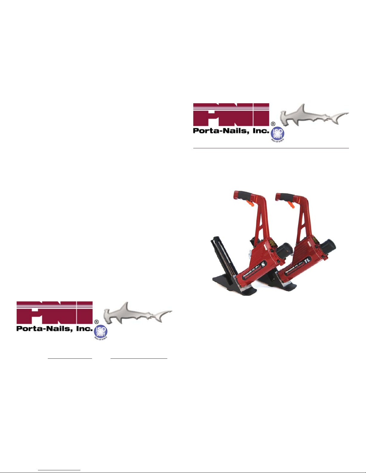
PORTAMATIC® 470 Hammerhead TL Nailer
PORTAMATIC® 472 Hammerhead S Stapler
For Tongue and Groove Solid Wood
& Hardwood Flooring
CAUTION - Read important safety instruc ons AND opera on
instruc ons BEFORE opera ng your Pneuma c Tool.
Your new Pneuma c Tool is capable of dependable performance throughout
its life me. To take full advantage of these capabili es you should thoroughly
understand the proper method and technique of its opera on. Therefore, we
suggest you read this manual before opera ng, and that you save it for future
reference.
For use with PORTAMATIC® 470 TL Nailers star ng with Serial No. 07042000.
For use with PORTAMATIC® 472 S Staplers star ng with Serial No. 05092000.
FORM P/N 470701 (4/22/2008)
Page 2

2
INTRODUCTION
This fl ooring tool is a precision-built tool designed for high speed,
high volume fastening. These tools deliver effi cient, dependable
service when used correctly and with care. As with any fi ne power
tool, for best performance the manufacturer’s instruc ons must be
followed. Please study this manual before opera ng the tool and
understand the safety warning and cau ons. The instruc on on
installa on, opera on and maintenance should be read carefully, and
the manual kept for reference. NOTE: Addi onal safety measures
may be required because of your par cular applica on of the
tool. Contact your representa ve or distributor with any ques ons
concerning the tool and its use.
INDEX
INTRODUCTION 2
WARRANTY 3
TOOL SPECIFICATIONS 4
SAFETY INSTRUCTIONS 5
SAFE OPERATION 6
AIR SUPPLY AND CONNECTIONS 8
LUBRICATION 9
LOADING THE TOOL 9
TOOL OPERATION 11
MAINTAINING THE PNEUMATIC TOOL 12
TROUBLE SHOOTING 14
NAIL / STAP LE LENGTH DETERMINATION CHART 15
SERVICING ASSEMBLY / DISASSEMBLY I
NSTRUCTIONS 16
EXPLODED VIEW – 470 HAMMERHEAD TL NAILER 18
470 – PART LISTING 19
EXPLODED VIEW – 472 HAMMERHEAD S STAPLER 21
472 – PART LISTING 22
TL NAILER / S STAP LER ACCESSORIES 24
FASTENERS 25
NOTES: 26
31
“PNI is a proud Member of these Industry Associa ons”
Page 3

30
NOTES:
3
LIMITED WARRANTY
(U.S. and Canada Only)
Porta-Nails, Inc. (PNI) is proud of the products it manufactures and warrants to the
original retail purchaser that the product purchased is free from defects in material
and workmanship, and agrees to repair or replace, at Porta-Nails’ op on, any
defec ve Porta-Nails branded pneuma c stapler or nailer for a period of one (1)
year from date of purchase. Warranty is not transferable. Proof of purchase date
required. This warranty covers only damage resul ng from defects in material or
workmanship; it does not cover condi ons or malfunc ons resul ng from normal
wear, neglect, abuse, accident or repairs a empted or made by other than our
na onal repair center or authorized warranty service centers. Driver blades,
bumpers, O-rings, pistons and piston rings are considered normally wearing parts.
For op mal performance of your Porta-Nails tool always use genuine Porta-Nails
fasteners and replacement parts.
THIS WARRANTY IS IN LIEU OF ALL OTHER WARRANTIES, EXPRESS OR IMPLIED,
INCLUDING BUT NOT LIMITED TO THE IMPLIED WARRANTIES OF MERCHANTABILITY
OR FITNESS FOR A PARTICULAR PURPOSE. PORTA-NAILS SHALL NOT BE LIABLE FOR
ANY INCIDENTAL OR CONSEQUENTIAL DAMAGES.
Some states and countries do not allow limita ons on how long an implied warranty
lasts, or the exclusion or limita on of incidental or consequen al damages, so the
above limita ons or exclusions may not apply to you. This warranty gives you specifi c
legal rights, and you may also have other rights which vary from state to state and
country to country.
Returns for warranty service or repair must be issued an RMA number prior to being
returned. To obtain warranty service in the U.S. call our offi ces at 1-800-634-9281 to
obtain a Returned Merchandise Authoriza on (RMA) and instruc ons for returning
the product, or visit www.porta-nails.com for the loca on of the authorized service
center most convenient for you.
Returns should be sent to:
Porta-Nails, Inc.
A en on: Service Department
4235 US Hwy 421 North
Currie, NC 28435
Page 4

4
TOOL SPECIFICATIONS
Model Length Height Width Weight
470 18” 18.8” 3-1/8” 9.00 lbs.
472 18” 18.8” 3-1/8” 9.10 lbs.
FASTENER SPECIFICATIONS:
Model
Fastener
Type
Crown
Width Gauge Lengths
470 “T”, “L” Nail 16 Ga. 1-1/2”, 2”
472 Staple 1/2” 15-15-1/2 Ga. 1-1/2”, 2”
TOOL AIR FITTING:
This tool uses a 3/8” NPT male plug. The inside diameter should be
.275” (7mm) or larger. The fi ng must be capable of discharging
tool air pressure when disconnected from the air supply.
OPERATING PRESSURE:
70 to 90 PSI Select the opera ng pressure within this range for
best fastener performance. DO NOT EXCEED THIS RECOMMENDED
OPERATING PRESSURE.
AIR CONSUMPTION:
The Tool requires 4.2 cubic feet per minute (221 liters per minute)
of free air to operate at the rate of 60 fasteners per minute @ 80 PSI
Take the actual rate at which the tool will be run to determine the
amount of air required. For instance, if your fastener usage averages
30 fasteners per minute, you need 50% of the tool’s C.F.M. of free air
which is required to operate the tool at 60 fasteners per minute.
Cau on regarding Use of this Tool to Install Pre-fi nished Flooring
This Flooring Tool was designed for use in installing unfi nished
hardwood fl ooring. It can be used to install pre-fi nished fl ooring
when used with the Pre-Finish fl ooring accessory shoe (P/N 47090);
however, cau on must be used to ensure that the fi nish is not
damaged by the tool. In all fl ooring applica ons, it is recommended
that the tool be tested on a sample sec on to be certain that the
tool and technique of use do not leave marks on the fi nish. This
procedure should be followed before each job due to varia ons in
fl ooring and tool condi on.
29
FASTENERS
PORTA-NAILS “T”:
(For use with Model 470 Portama c TL and Model 421 Portama c Hammerhead 2)
42623 2” T-Nails (10 packages of 1000 Nails).
42629 2” T-Nails (Box of 1000 Nails)
Order in Qtys. of Ten (10).
42660 2” Stainless Steel T-Nails Box of 1000 Nails.
(ACQ Treated Lumber Approved).
42640 1-1/2” T-Nails - Box of 1000 Nails
Order in Qtys. of Five (5).
42646 1-3/16” T-Nails - Box of 1000 Nails
Order in Qtys. of Five (5).
PORTA-NAILS “L”:
(For use with Model 470 Portama c TL)
47020 2” L-Nails (10 packages of 1000 Nails)
4702 2” L-Nails - Box of 1000 Nails
Order in Qtys. of Ten (10).
47040 1-1/2” L-Nails (5 packages of 1000 Nails)
4704 1-1/2” L-Nails - Box of 1000 Nails
Order in Qtys. of Ten (10).
STAPLES:
(For use with Model 472 Portama c S)
47261 2” 15Ga. Staples (1000 Staples)
4722 2” 15Ga. Staples (5000 Staples)
47281 2” 15Ga. Stainless Steel Staples (1000 Staples)
(ACQ Treated Lumber Approved)
4725 2” 15Ga. Stainless Steel Staples (5000 Staples)
(ACQ Treated Lumber Approved)
47271 1-1/2” 15Ga. Staples (1000 Staples)
4724 1-1/2” 15Ga. Staples (7500 Staples)
Page 5

28
TL NAILER / S STAPLER ACCESSORIES
Part No. Descrip on
47075 Hammer Assy – Graphite
47061 O-ring Kit
47060 Service Parts Kit
47062 Piston Rod Assembly
47065 Extension Handle Assembly – Short
47066 Extension Handle Spacer 4”
47067 Shoe Base Pad – 1/2” Flooring
47068 Oil – Tool
47011 Gasket
47069 Box Wrench
47070 Hex Wrench – 4 MM
47071 Hex Wrench – 5 MM
47072 Hex Wrench – 6 MM
47050 Carrying Case – 470 / 472
50231 Air Hose Kit
50232 Air Dryer Kit
50233 Air Filter / Regulator Kit
50170 Safety Glasses
50525 PortaPro-Air Compressor
47100 PortaJack-Pro Floor Tightening Jack
47090 Pre-Finished Flooring Shoe – 470 / 472
47061 O-ring Kit 47062 Piston Rod Assembly
Part No. Descrip on Part No. Descrip on
47002 O-ring - Cap 47012 Poppet
47007 O-ring – Plunger OD 47009 Piston Rod
47008 O-ring – Piston Rod OD 47016 Piston
47013 O-ring – Poppet ID 47008 O-ring – Piston Rod OD
47015 O-ring – Piston OD 47013 O-ring – Poppet ID
47015 O-ring – Piston OD
47060 Service Parts Kit
Part No. Descrip on
47023 Piston Cushion
47067 Shoe Base Pad – 1/2” Flooring
47068 Oil – Tool
47011 Gasket
47069 Box Wrench
47070 Hex Wrench – 4 MM
47071 Hex Wrench – 5 MM
47072 Hex Wrench – 6 MM
47061 O-ring Kit
5
SAFETY INSTRUCTIONS
Tool Opera on
The employer is responsible for ensuring that the manufacturer’s
tool opera ng/safety instruc ons are available to operators.
The employer and the tool operator are responsible for the safe use
of the tool.
The employer and tool operator are responsible for selec ng an
appropriate tool actua on system from op ons available, taking into
considera on the work applica ons for which the tool is used.
It is the responsibility of the employer and the tool operator to
ensure that the tools are used only when the tool operator and
all other personnel in the work area are wearing eye protec on
equipment and when required, other appropriate protec on
equipment such as head, hearing and foot protec on equipment.
Safety Eye and Face Protec on Equipment
Safety eye and face protec on equipment shall conform to the
requirements of ANSI Z87.1 and shall provide protec on against
fl ying par cles both from the front and side or shall be determined
by the U.S. Department of Labor’s Occupa onal Safety and Health
Administra on (OSHA) to provide protec on equivalent to eye
protec on conforming to the requirements of ANSI Z87.1 and shall
provide protec on against fl ying par cles both from the front and
side.
Head Protec on Equipment
Head protec on shall conform to American Na onal Standards
Ins tute Z89.1, “Protec ve Headwear for Industrial Workers”.
TOOL MAINTENANCE
When working on air tools note the warnings in this manual and use
extra care when evalua ng problem tools.
Responsibility for Proper Tool Maintenance
The employer and tool operator are responsible for assuring that the
tool is kept in safe working order as described in the Tool Opera ng/
Safety Instruc ons. Only qualifi ed personnel shall repair the tool.
The employer is responsible for ensuring that the manufacturer’s
tool maintenance instruc ons are available to personnel performing
maintenance.
Page 6

6
Repair Parts and Accessories
Tools shall be repaired or equipped only with parts or accessories
that are supplied or recommended by the tool manufacturer, or with
parts or accessories which perform equivalently to those supplied or
recommended by the tool manufacturer.
Tools Needing Repair
The employer shall ensure that tools which require repair are
not further used before repair. Tags and physical segrega on are
recommended means of control. OSHA’s General Industry and
Construc on regula ons require the use of tags.
Tool Maintenance Instruc ons
The employer is responsible for ensuring that the tool maintenance
instruc ons are available to the appropriate personnel.
The employer is responsible for the proper maintenance of all tools
in its possession.
Only qualifi ed personnel shall repair the tool and shall use
parts or accessories that are supplied or recommended by the
tool manufacturer, or with parts or accessories which perform
equivalently to those supplied or recommended by the tool
manufacturer.
TOOL OPERATING/SAFETY INSTRUCTIONS
Eye Protec on
WARNING:
!
Eye protec on equipment must be worn by the
operator and other people in the work area.
WARNING:
!
The employer is responsible to enforce the use of
eye protec on equipment by the tool operator
and all other personnel in the work area.
Opera on
Appropriate personal protec ve equipment is to be worn.
Inspect the tool before opera ng to:
Establish use of proper power source as set forth in this •
manual under Power Source.
Determine that the tool is in proper working order.•
An improperly func oning tool must not be used.
Tool Handling
Always assume that the tool contains fasteners.•
27
NAIL / STAPLE LENGTH DETERMINATION CHART
This chart will assist you in determining the proper length of NAIL/
STAPLE to use for various thickness of fl ooring when the sub-fl ooring
member varies as to species and thickness and for determina on for
use when installing over concrete. Ver cal penetra on of the NAIL/
STAPLE under the hardwood fl oor is shown for each applica on.
31/32"
19/32"
1 1/8"
25/32"
3/4" FLOO RING
1/2" FLOO RING
2" FASTENER
1-1/2" FASTENER
2" FASTENER
1-1/2" FASTENER
Page 7

26
33 47074 SCREW – HANDLE CAP
34 47236 SCREW – MAGAZINE STAND-OFF
35 47241 SCREW – PUSHER STOP
36 47044 CONSTANT FORCE SPRING
37 47037 MAGAZINE SPACER / STAND-OFF
38 47235 STAPLE GUIDE UNIT
39 47042 SCREW – CONSTANT FORCE SPRING
40 47240 PUSHER FINGER
41 47232 SCREWS – NOSE / MAGAZINE
42 – NOT ASSIGNED
43 – NOT ASSIGNED
44 – NOT ASSIGNED
45, 45A 47028 SCREW – FOOT / MAGAZINE
46 47029 FOOT
47 47032 SPRING PIN – FOOT / DRIVER GUIDE PLATE
48 47244 DRIVER GUIDE PLATE – 472
49 47242 NOSE – 472
50 47234 MAGAZINE – 472
51 47239 SCREWS – MAGAZINE / STAPLE GUIDE
52 47027 SHOE
53 47025 SHOE BASE PAD
54 47024 SCREW – SHOE BASE
55, 55A 47026 SCREWS – SHOE / FOOT / BODY
56* 47047 LOCK NUT – SHOE BASE
57* 47075 HAMMER ASSY – GRAPHITE
*NOT SHOWN IN ILLUSTRATION
7
Do not point the tool toward yourself or anyone whether it •
contains fasteners or not.
Do not actuate the tool unless the tool is placed fi rmly against •
the work piece.
Respect the tool as a working implement.•
Never engage in horseplay.•
Do not hold or carry the tool with a fi nger on the trigger.•
Do not load the tool with fasteners when any one of the •
opera ng controls is ac vated.
Do not operate the tool with any power source other than •
that specifi ed in the tool opera ng/safety instruc ons.
Opera ng Controls
Do not remove, tamper with, or otherwise cause the tool •
opera ng controls to become inoperable.
Do not operate a tool if any por on of the tool opera ng •
controls is inoperable, disconnected, altered, or not working
properly.
Disconnec ng the Tool
Disconnect the tool from the power source when:
Una ended.•
Performing any maintenance or repair.•
Clearing a jam.•
Moving the tool to a new loca on.•
Recommended Fasteners
Use only fasteners made or recommended by the tool manufacturer,
or fastener which perform equivalently to those recommended by
the manufacturer.
Tool Modifi ca on
The wri en approval of the tool manufacturer must be obtained
prior to making any modifi ca ons to the tool.
Other Detailed Informa on
Refer to the tool maintenance instruc ons for detailed informa on
on the proper maintenance of the tool.
Page 8

8
Actua on System
This tool u lizes a dual trigger single sequen al actua on system.
The safety trigger located within the handle must be held depressed
and the ram cap must be struck with the included mallet to
actuate the tool. The ram cap must be struck with the mallet for
each subsequent actua on provided that the safety trigger is held
depressed for subsequent actua ons. The safety trigger is included
to prevent accidental actua on of the tool. Repeated a empts to
actuate the tool while the safety trigger is released may damage the
safety mechanism and the tool.
Power Source
The compressed air power source shall be pressure-regulated. The
regulated pressure must not exceed the maximum air pressure
marked on the tool. If a regulator fails, the pressure delivered to the
tool must not exceed 1.5 mes the maximum air pressure, or 200
PSIG, whichever is greater. The tool normally is not operated at the
maximum air pressure but at a lower pressure determined by the
type of fastener used, the work piece, and other condi ons of use.
Hazardous Power Source
Hazardous power sources shall not be used. Hazardous power
sources include, but are not limited to the following:
Reac ve gases including, but not limited to oxygen and •
combus ble gases.
Pressure sources that can deliver in excess of 1.5 mes the •
maximum air pressure of the tool or 200 PSIG, whichever is
greater, if a regulator fails.
Regulator
Pressure regulators shall be used to limit the air pressure supplied
to the tool. Regulators shall be set at an opera ng pressure which is
lower than or equal to the tool manufacturer’s specifi ed maximum
air pressure.
Hose
Air supply hoses shall have a minimum working pressure ra ng equal
to or greater than the pressure from the power source if a regulator
fails, or 150 PSIG, whichever is greater.
Disconnect
Tools shall be fi ed with a fi ng or hose coupling on or near the tool
25
472 – PART LISTING
472 Part No. Descrip on
1 47001 RAM CAP
2 47002 O-RING – CAP
3, 3A 47003 SCREW – SOCKET HEAD CAP
4 47004 CAP
5, 5A 47005 SCREWS – PLUNGER
6 47006 PLUNGER
7 47007 O-RING - PLUNGER OD
8 47063 RETURN SPRING
9 47011 GASKET
10 47008 O-RING – PISTON ROD OD
11 47009 PISTON ROD
12 47012 POPPET
13 47013 O-RING – POPPET ID
14 47022 SEAL – POPPET OD
15 47016 PISTON
16 47015 O-RING – PISTON OD
17 47010 BALL PIN
18 47243 DRIVER BLADE – 472
19 47017 LOCK NUT – PISTON/DRIVER BLADE
20 47023 PISTON CUSHION
21 47021 PLATE
22 47019 BODY
23 47035 SAFETY PLATE
24 47046 SCREW – SAFETY PLATE
25 47049 SPRING – SAFETY
26 47051 CABLE – SAFETY
27 47058 ELBOW
28 47052 QUICK CONNECT - MALE
29 47045 HANDLE
30 47053 SAFETY TRIGGER
31 47054 PIN – SAFETY TRIGGER
32 47073 CAP – HANDLE
Page 9

24
EXPLODED VIEW – 472 HAMMERHEAD S STAPLER
9
in such a manner that all compressed air in the tool is discharged at
the me the fi ng or hose coupling is disconnected.
TOOL OPERATION
BEFORE HANDLING OR OPERATING THIS TOOL READ AND
UNDERSTAND THE WARNINGS CONTAINED IN THIS MANUAL.
IN ADDITION TO THE OTHER WARNINGS CONTAINED IN THIS MANUAL
OBSERVE THE FOLLOWING FOR SAFE OPERATION.
Use the pneuma c tool only for the purpose for which it was •
designed.
Do not e, tape, or otherwise disable the safety trigger as this •
could result in accidental discharge of the tool causing injury to
yourself and others.
Never use this tool in a manner that could cause a fastener to •
be directed toward the user or others in the work area.
Do not strike the ram/actuator without pulling the safety •
trigger. Hi ng the tool repeatedly with the safety interlock
engaged will severely damage the safety mechanism and the
tool. This abuse and damage is not covered by the warranty.
Do not use the tool as a hammer.•
Always carry the tool by the handle. Never carry the tool by •
the air hose.
Always be aware that misuse and improper handling of this tool •
can cause injury to yourself and others.
Never leave a tool una ended with the air hose a ached.•
Do not operate this tool if it does not contain a legible •
WARNING LABEL.
Do not con nue to use a tool that leaks air or does not func on •
properly. No fy your nearest store representa ve if your tool
con nues to experience func onal problems.
Always handle the tool with care. Never engage in horseplay. •
Never pull the trigger unless nose is directed toward the
work. Keep others a safe distance form the tool while tool is in
opera on as accidental actua on may occur, possibly causing
injury.
The operator must not hold the safety trigger pulled except •
during fastening opera on as serious injury could result if the
ram cap accidentally contacted someone or something with
Page 10

10
enough force to cause the tool to cycle.
Keep hands and body away from the discharge area of the tool. •
The tool may bounce from the recoil of driving a fastener and
an unwanted second fastener may be driven possibly causing
injury.
When loading tool, never place a hand or any part of body in •
fastener discharge area of tool, never point tool at anyone,
do not pull the safety trigger or depress the ram/actuator as
accidental actua on may occur, possibly causing injury.
Always disconnect the air supply before making adjustments, •
when servicing the tool, when clearing a jam, when tool is not
in use, or when moving to a diff erent work area, as accidental
actua on may occur, possibly causing injury.
Check opera on of the safety mechanism frequently. Do not •
use the tool if the safety is not working correctly as accidental
driving of a fastener may result. Do not interfere with the
proper opera on of the safety mechanism.
The safety trigger is a safety device and should only be pulled •
when the tool is in proper posi on on the work surface and
before the ram/actuator is struck with the mallet. Do not e
or tape down the safety trigger as the tool could discharge if
dropped on the plunger. The tool will not fi re unless the trigger
is pulled before striking the ram/actuator with the mallet.
Do not use the safety as a disabling mechanism for the ram/•
actuator in order to use the tool to rack the wood. This will
severely damage the mechanism and the tool. This abuse and
damage is not covered by the warranty. Use the mallet to rack
the fl ooring, not the tool.
Do not strike the ram/actuator without pulling the safety •
trigger! Hi ng the tool repeatedly with the safety engaged will
damage the safety mechanism and the tool.
Do not drive fasteners on top of other fasteners or with the •
tool at an overly steep angle as this may cause defl ec on of
fasteners which could cause injury.
Do not strike the ram/actuator or any part of the tool with the •
metal por on of the mallet. Use the rubber capped end only to
prevent possible injury and/or damage to the tool.
Do not drive fasteners close to the end of the work piece as the •
wood may split, allowing the fastener to be defl ected possibly
23
33 47074 SCREW – HANDLE CAP
34 47036 SCREW – MAGAZINE STAND-OFF
35 47048 ROLLER – SPRING
36 47044 CONSTANT FORCE SPRING
37 47037 MAGAZINE SPACER / STAND-OFF
38 47043 ROLLER WHEEL
39 47042 SCREW – CONSTANT FORCE SPRING
40 47041 PUSHER FINGER
41 47057 SPRING – COMPRESSION
42 47039 PUSHER BRACKET
43 47056 O-RING – PUSHER PIVOT PIN
44 47055 PUSHER PIVOT PIN
45, 45A 47028 SCREWS – FOOT / MAGAZINE
46 47029 FOOT
47 47032 SPRING PIN – FOOT / DRIVER GUIDE PLATE
48 47031 DRIVER GUIDE PLATE
49 47033 NOSE – 470 – T/L
50 47034 MAGAZINE – 470 – T/L
51 47038 NUT – MAGAZINE / STANDOFF SCREWS
52 47027 SHOE
53 47025 SHOE BASE PAD
54 47024 SCREW – SHOE BASE
55, 55A 47026 SCREWS – SHOE / FOOT / BODY
56* 47047 LOCK NUT – SHOE BASE
57* 47075 HAMMER ASSY – GRAPHITE
*NOT SHOWN IN ILLUSTRATION
Page 11

22
470 – PART LISTING
470 Part No. Descrip on
1 47001 RAM CAP
2 47002 O-RING – CAP
3, 3A 47003 SCREW – SOCKET HEAD CAP
4 47004 CAP
5, 5A 47005 SCREWS – PLUNGER
6 47006 PLUNGER
7 47007 O-RING - PLUNGER OD
8 47063 RETURN SPRING
9 47011 GASKET
10 47008 O-RING – PISTON ROD OD
11 47009 PISTON ROD
12 47012 POPPET
13 47013 O-RING – POPPET ID
14 47022 SEAL – POPPET OD
15 47016 PISTON
16 47015 O-RING – PISTON OD
17 47010 BALL PIN
18 47014 DRIVER BLADE
19 47017 LOCK NUT – PISTON/DRIVER BLADE
20 47023 PISTON CUSHION
21 47021 PLATE
22 47019 BODY
23 47035 SAFETY PLATE
24 47046 SCREW – SAFETY PLATE
25 47049 SPRING – SAFETY
26 47051 CABLE – SAFETY
27 47058 ELBOW
28 47052 QUICK CONNECT - MALE
29 47045 HANDLE
30 47053 SAFETY TRIGGER
31 47054 PIN – SAFETY TRIGGER
32 47073 CAP – HANDLE
11
causing an injury.
Do not overdrive fasteners. NOFMA states that one reason for •
split tongues is over driving.
Page 12

12
AIR SUPPLY AND CONNECTIONS
FITTINGS:
Install a male plug on the tool which is free fl owing and which will
release air pressure from the tool when disconnected from the
supply source.
HOSES:
Air hoses should have a minimum of 150 PSI working pressure ra ng
or 150 percent of the maximum pressure that could be produced
in the air system. The supply hose should contain a fi ng that will
provide “quick disconnec ng” from the male plug on the tool.
SUPPLY SOURCE:
Use only clean regulated compressed air as a power source for this
tool. NEVER USE OXYGEN, COMBUSTIBLE GASES, OR BOTTLED
GASES, AS A POWER SOURCE FOR THIS TOOL AS TOOL MAY
EXPLODE.
REGULATOR:
A pressure regulator with an opera ng pressure of 0-125 PSI is
required to control the opera ng pressure for safe opera on of this
tool. Do not connect this tool to air pressure which can poten ally
exceed 200 PSI as tool may fracture or burst, possibly causing injury.
OPERATING PRESSURE:
Do not exceed recommended maximum opera ng pressure as tool
wear will be greatly increased. The air supply must be capable of
maintaining the opera ng pressure at the tool. Pressure drops in
the air supply can reduce the tool’s driving power. Refer to “TOOL
SPECIFICATIONS” for se ng the correct opera ng pressure of tool.
FILTER:
Dirt and water in the air supply are major causes of wear in
pneuma c tools. A fi lter will help to get the best performance and
minimum wear from the tool. The fi lter must have adequate fl ow
capacity for the specifi c installa on. The fi lter has to be kept clean
to be eff ec ve in providing clean compressed air to the tool. Consult
the manufacturer’s instruc ons on proper maintenance of your fi lter.
A dirty and clogged fi lter will cause a pressure drop which will reduce
the tool’s performance.
LOADING THE TOOL
Never place a hand or any other part of the body in nail discharge •
21
EXPLODED VIEW – 470 HAMMERHEAD TL NAILER
Page 13

20
Replace the Cap with four (4) Socket Head Cap Screws and 17.
ghten.
Replace the Ram Cap.18.
Check the tool opera on as explained in the Owner’s Manual and 19.
inspect for leaks.
DETAILS OF 47062 PISTON ROD ASSEMBLY
13
area of tool while the air supply is connected.
Never point the tool at anyone else.•
Never engage in horseplay.•
Never pull the trigger unless nose is directed at the work.•
Always handle the tool with care.•
Do not pull the trigger or depress the trip mechanism while loading •
the tool.
PORTAMATIC® 470 Hammerhead TL Nailer
NAIL LOADING:
Insert “L” or “T” Nails in the end of the Magazine as shown.
Pull Pusher Assembly back to engage Pusher to strip of Nails. The
Tool is now ready to operate.
PORTAMATIC® 472 Hammerhead S Stapler
STAPLE LOADING:
Pull Pusher back. Insert a clip of Staples. Push Pusher forward to
engage the Staple Clip. The Tool is now ready to operate.
LUBRICATION
Page 14

14
Frequent, but not excessive, lubrica on is required for best
performance. Oil added through the air line connec on will lubricate
the internal parts. Use Air Tool Lubricant, Mobil Velocite #10, or
equivalent. Do not use detergent oil or addi ves as these lubricants
will cause accelerated wear to the seals and Piston Cushion in
the tool, resul ng in poor tool performance and frequent tool
maintenance.
If no airline lubricator is used, add oil during use into the air fi ng
on the tool once or twice a day. Only a few drops of oil at a me are
necessary. Too much oil will only collect inside the tool and will be
no ceable in the exhaust cycle.
COLD WEATHER OPERATION:
For cold weather opera on, near and below freezing, the moisture in
the air line may freeze and prevent tool opera on. We recommend
the use of WINTER FORMULA air tool lubricant (NEW-MATIC Winter
Formula or equivalent) or permanent an freeze (ethylene glycol) as a
cold weather lubricant.
CAUTION: Do not store tools in a cold weather environment to
prevent frost or ice forma on on the tools opera ng valves and
mechanisms that could cause tool failure.
NOTE: Some commercial air line drying liquids are harmful to
O-rings and seals – do not use these low temperature air dryers
without checking compa bility.
19
SERVICING ASSEMBLY / DISASSEMBLY INSTRUCTIONS
Remove Ram Cap with Box Wrench.1.
Remove four (4) Socket Head Cap Screws. Take off Cap. Note 2.
presence of O-ring which remains in the Cap.
Remove four (4) Socket Head Cap Screws that connects the 3.
Plunger to the Poppet. Pull the Plunger out of the cylinder and
remove the O-ring.
Remove O-ring and clean ma ng surfaces on the Plunger and 4.
Poppet.
Remove four (4) Socket Head Cap Screws thus detaching the 5.
Shoe/Magazine Assembly from the Body.
Manually pull the rubber Piston Cushion out of the Body. Visually 6.
inspect the Piston Cushion for wear, deforma on and/or cracking.
If defec ve, replace.
Grasp the Driver Blade with thumb and forefi nger and pull out of 7.
cylinder Body. The Piston, Poppet and Piston Rod will follow.
Unscrew the Lock Nut from the Piston Rod. Do not deform the 8.
so aluminum part, use the Box Wrench. Slide the Piston off of
the Piston Rod.
Clean all parts with a clean dry rag.9.
Install new O-rings according to the accompanying drawing. Coat 10.
the O-rings, grooves, and cylinder walls evenly with grease and
install.
Reassemble the Poppet and Piston onto the Piston Rod. Insert 11.
the Driver Blade into the slot and pin into the hole. Thread the
Lock Nut un l it is exactly fl ush with the end of the Piston Rod.
Reinsert the Piston Rod followed by the Poppet, Piston and Driver
Blade in the Body.
Reinstall the Piston Cushion into the Body fl ush with the bo om.12.
Guide the Shoe/Magazine Assembly onto the Driver Blade and 13.
press up against the Body. Insert and ghten the four (4) Socket
Head Cap Screws through the Shoe and into the Body.
Returning to the top por on of the tool, reinstall the new Gasket 14.
onto the Plunger. Insert the Plunger with new O-ring into the
Body cylinder using an alignment tool / rod to align the four (4)
screw holes in the Plunger to the threaded holes in the Poppet.
Using Loc te on the threads, insert the four (4) new screws with 15.
spring washer and ghten the Plunger to the Poppet.
Reinstall new Cap.16.
Page 15

18
TROUBLE SHOOTING (Con nued)
PROBLEM CAUSE CORRECTION
Skipping fasteners;
intermi ent feed
(cont’d)
Broken/chipped driver Replace Driver (check
Piston O-ring)
Dry/dirty magazine Clean/lubricate use Air
Tool Lubricant
Worn magazine Replace magazine
Fasteners jam in tool Driver channel worn Replace nose/check door
Wrong size fasteners Use only recommended
fasteners
Bent fasteners Discon nue using these
fasteners
Loose magazine nose
screws
Tighten all screws
Broken/chipped driver Replace Driver (check
Piston O-ring)
15
MAINTAINING THE PNEUMATIC TOOL
When working on air tools, note the warnings in this manual and use
extra care evalua ng problem tools.
CAUTION: Pusher Spring (constant force spring). Cau on must be
used when working with the spring assembly. The spring is wrapped
around, but not a ached to a roller. If the spring is extended beyond
its length, the end will come off the roller and the spring will roll up
with a snap, with a chance of pinching your hand. Also, the edges
of the spring are very thin and could cut. Care must also be taken to
insure no permanent kinks are put in the spring as this will reduce
the spring’s force.
ASSEMBLY PROCEDURE FOR SEALS:
When repairing a tool, make sure the internal parts are clean and
lubricated. Use LITHIUM grease or equivalent on all O-rings. Coat
each O-ring with “O”-LUBE before assembling. Use a small amount
of oil on all moving surfaces and pivots. A er re-assembly, add a few
drops of Air Tool Lubricant through the air line fi ng before tes ng.
AIR SUPPLY-PRESSURE AND VOLUME:
Air volume is as important as air pressure. The air volume supplied
to the tool may be inadequate because of undersized fi ngs and
hoses or from the eff ects of dirt and water in the system. Restricted
air fl ow will prevent the tool from receiving an adequate volume of
air, even though the pressure reading is high. The results will be slow
opera on, jamming, miss-feeds or reduced driving power. Before
evalua ng tool problems for these symptoms, trace the air supply
from the tool to the supply source for restric ve connectors, swivel
fi ngs, low points containing water and anything else that would
prevent full volume fl ow of air to the tool.
DRIVER BLADE ASSEMBLY / REMOVAL:
Disconnect the air supply.1.
Remove the Ram Cap with box wrench.2.
Unscrew & remove Body Cap.3.
Unscrew the four Cap Screws holding the Plunger to the Poppet.4.
Pull the Plunger up and out of the Body Cavity.5.
Turn the tool over and remove the four Cap Screws that fasten 6.
the Shoe Assembly and the Magazine Assembly to the tool Body.
Remove the assemblies off the body.
Remove the rubber Piston Cushion.7.
Pull the Driver Blade Assembly out of the Body.8.
Page 16

16
Hold the Piston Rod with a box wrench over its Hex End and 9.
opposite the Lock Nut. Do not use Pliers anywhere on the metal
parts as they can damage the sealing surfaces.
Remove the Lock Nut, Pin and the Driver Blade.10.
Unscrew the Piston from the Piston Rod. Separate the Piston, 11.
Piston Rod and the Poppet.
TO REPLACE DRIVER BLADE:
Holding the piston rod with box wrench, remove the lock nut.1.
Push out the pin and remove the driver blade.2.
Install a new driver blade in the slot and replace the pin.3.
Screw on the Retaining Lock Nut using the same tools. If the lock 4.
nut becomes worn and loose a er frequent removals, it should
be replaced.
Check the fi t. There should be some sideways movement 5.
between the Driver Blade and the Lock nut assembly. This is
desirable and helps the Driver Blade to align itself with ma ng
parts.
Reassemble the components and be sure to align the Driver 6.
Blade with the slot in the Adapter Foot Assembly.
TO REPLACE DRIVER GUIDE PLATE AND NOSE:
Separate the Magazine form the Shoe by removing the four 1.
Socket Head Cap Screws.
Remove and replace the Driver Guide Plate and Nose.2.
17
TROUBLE SHOOTING
PROBLEM CAUSE CORRECTION
Trigger valve housing
leaks air
O-ring cut or cracked Replace O-ring
Trigger valve stem
leaks air
O-ring/seals cut or
cracked
Replace trigger valve
assembly
Frame/nose leaks air Loose nose screws Tighten and recheck
O-ring is cut or cracked Replace O-ring
Piston Cushion is cracked/
worn
Replace Piston Cushion
Frame/cap leaks air Damaged seal Replace Seal
Loose cap screws Tighten and recheck
Failure to cycle Air supply restric on Check air supply
equipment
Tool dry, lack of
lubrica on
Use Air Tool Lubricant
Worn head valve O-rings Replace O-rings
Lack of power; slow to
cycle
Tool dry, lack of
lubrica on
Use Air Tool Lubricant
Broken cylinder cap
spring
Replace cap spring
O-rings/Seals cut or
cracked
Replace O-rings / Seals
Exhaust blocked Check Piston Cushion,
head valve spring, muffl er
Dirt/tar build up on driver Disassemble nose/driver
to clean
Head valve dry Disassemble / lubricate
Air pressure too low Check air supply
equipment
Skipping fasteners;
intermi ent feed
Worn Piston Cushion Replace Piston Cushion
Tar/Dirt in driver channel Disassemble and clean
nose and driver
Air restric on/inadequate
air fl ow through quick
disconnect socket and
plug
Replace quick disconnect
fi ngs
Worn piston O-ring Replace O-ring check
driver
Tool dry, lacks lubrica on Use Air Tool Lubricant
Damaged pusher spring Replace spring
Low air pressure Check air supply system
to tool
Loose magazine nose
screws
Tighten all screws
Fasteners too short for
tool
Use only recommended
fasteners
Bent fasteners Discon nue using these
fasteners
Wrong size fasteners Use only recommended
fasteners
 Loading...