

Page 1
OWNER’S MANUAL
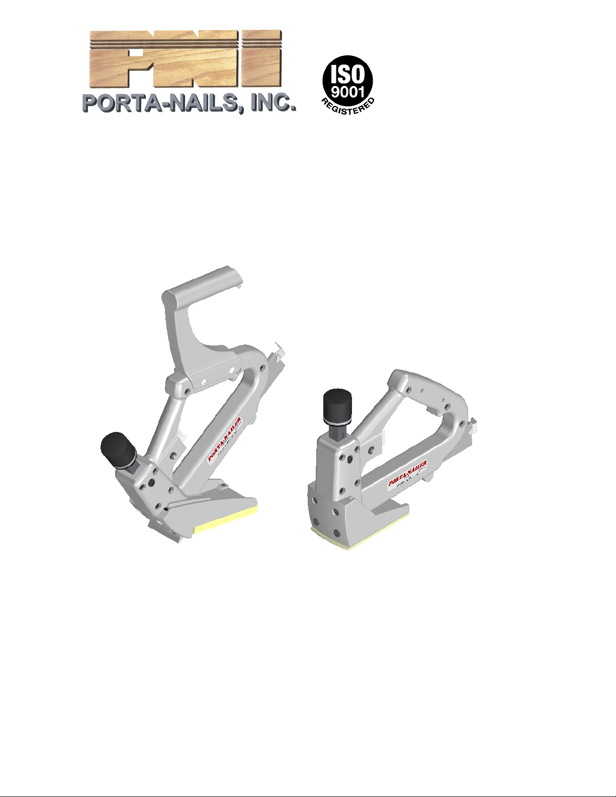
MODEL 402
PORTA-NAILER
For Tongue and Groove Solid Wood & Hardwood
Laminate Flooring
CAUTION - Read important safety instructions AND
operation instructions for proper operation of your Nailer.
Your new PORTA-NAILER is a quality-built machine, capable
of dependable performance throughout its lifetime. To take full
advantage of these capabilities you should thoroughly understand
the proper method and technique of its operation. Therefore, we
suggest you read this manual before operating and that you save it
for future reference.
FORM P/N 840256 (10/1/2002)
Page 2
MODEL 402
PORTA-NAILER
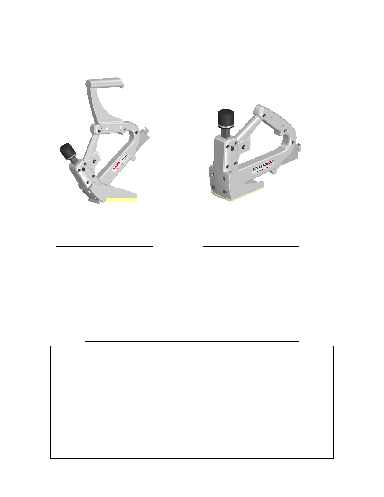
CAT. NO. 402
SPECIFICATIONS
Model 402 Porta-Nailer
with Angled Shoe
To be used for installing
5/8”, 3/4” – 33/32” Tongue
and Groove Flooring
To be used for face nailing the
first two (2) rows and the last
CAT. NO. 404
SPECIFICATIONS
Model 402 Porta-Nailer
with Face Shoe
six (6) rows of Tongue and
Groove Flooring
PNI’s LIMITED ONE YEAR WARRANTY
PNI is proud of the products that it manufacture s a nd warrants them to be free from
defects in materials and workmanship for 1 year. In the unlikely event that a
problem occurs, return the product to our plant freight prepaid and allowed, so that
a determination of the fault can be made. If the fault is determined to be defective
materials or workmanship, a no-char ge replacement or repair will be made, at our
discretion. The product will be returned to you freight prepaid and allowed. This
warranty does not cover accidents, abuse or misuse and in no case will PNI be
liable for incidental or consequential damages. No other warranty written or verbal
is authorized. Returns for warranty service should be sent to:
Porta-Nails, Inc.
4235 US Hwy. 421 N.
Currie, NC 28435
2
Page 3

SAFETY RULES FOR PORTA-NAILER
1. WEAR SAFETY CLASSES and safety shoes for
protection against foreign objects.
2. NEVER use a Hammer with a loose head or splintered
handle.
3. USE ONLY nails from Porta-Nails, Inc.
4. REPLACE worn or damaged parts immediately.
APPLICATIONS
•
Your Model 402 Porta-Nailer is designed for Angle
Nailing 5/8”, 3/4”-33/32” Hardwood Tongue and
Groove Flooring.
• An Accessory Shoe is available for Face Nailing. (See
Shoe Accessory Applications section)
• An Accessory Shoe is available for Angle Nailing 3/8”
to 9/16” Flooring with the standard 2” Porta-Nail. (See
Shoe Accessory Applications section)
•
An Accessory Angled Base is available for use with
the 402 Nailer to nail 3/4” Hardwood Tongue and
Groove Flooring over 3/4” Plywood over concrete.
(See Shoe Accessory Applications section)
3
Page 4
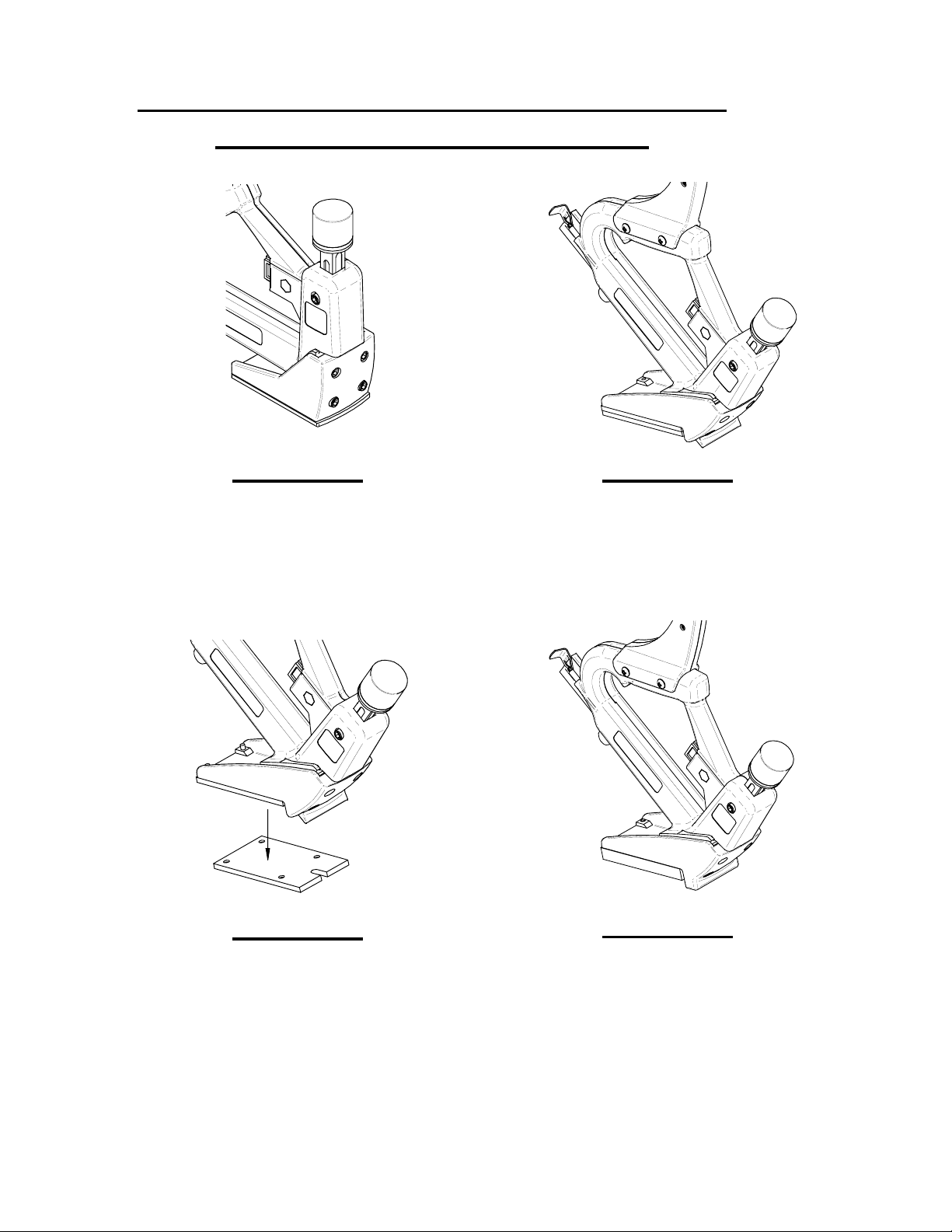
PORTA-NAILER ACCESSORY SHOE &
SHOE BASE APPLICATIONS
FIGURE 1
Face Nailing Shoe
Accessory Shoe Cat. No.
40225
FIGURE 2
Tongue Nailing 5/8”, 3/4”
Flooring Shoe
Standard Shoe
FIGURE 3
Tongue Nailing
33/32” Flooring
Standard Shoe with only
One (1) Shoe base installed.
FIGURE 4
Tongue Nailing
3/8”-9/16” Flooring
Accessory Shoe Cat. No.
40230
4
Page 5

FIGURE 5
Angled Shoe Base
Angled Shoe Base for Nailing 3/4” Flooring
over 3/4” Plywood over Concrete
Accessory Shoe Cat. No. 42626
ASSEMBLING THE EXTENSION HANDLE
Fasten the Extension Handle to the Nailer using the two (2) Screws
and Nuts (Ref. No. 38) furnished with the unit.
38
38
FIGURE 6
Installing the Extension Handle
5
Page 6
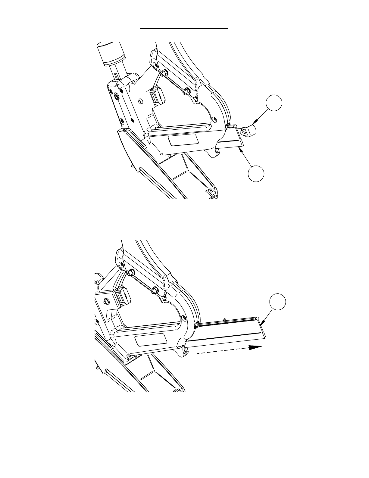
LOADING NAILS
17
20
1. Unhook the Connector (Ref. No. 17) from the Pusher (Ref. No.
20).
20
2. Remove the Pusher (Ref. No. 20) from the Nail Rail.
6
Page 7
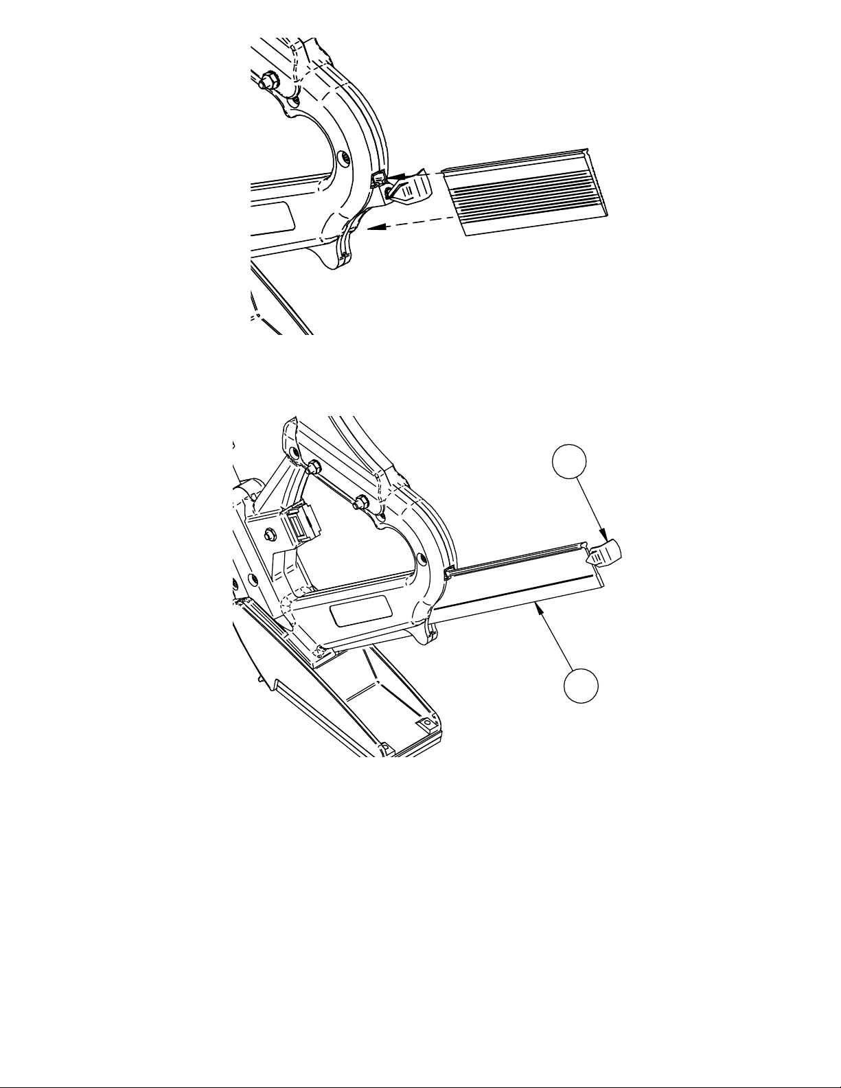
3. Insert a stack of Nails into the Nail Rail with the Heads “up”.
17
20
4. Place the Pusher (Ref. No. 20) in the Nail Rail and hook the
Connector (Ref. No. 17) to the Pusher (Ref. No. 20).
WARNING:
For proper operation never use Nailer with less than a 2
inch stack of nails remaining in the Nail Rail.
7
Page 8
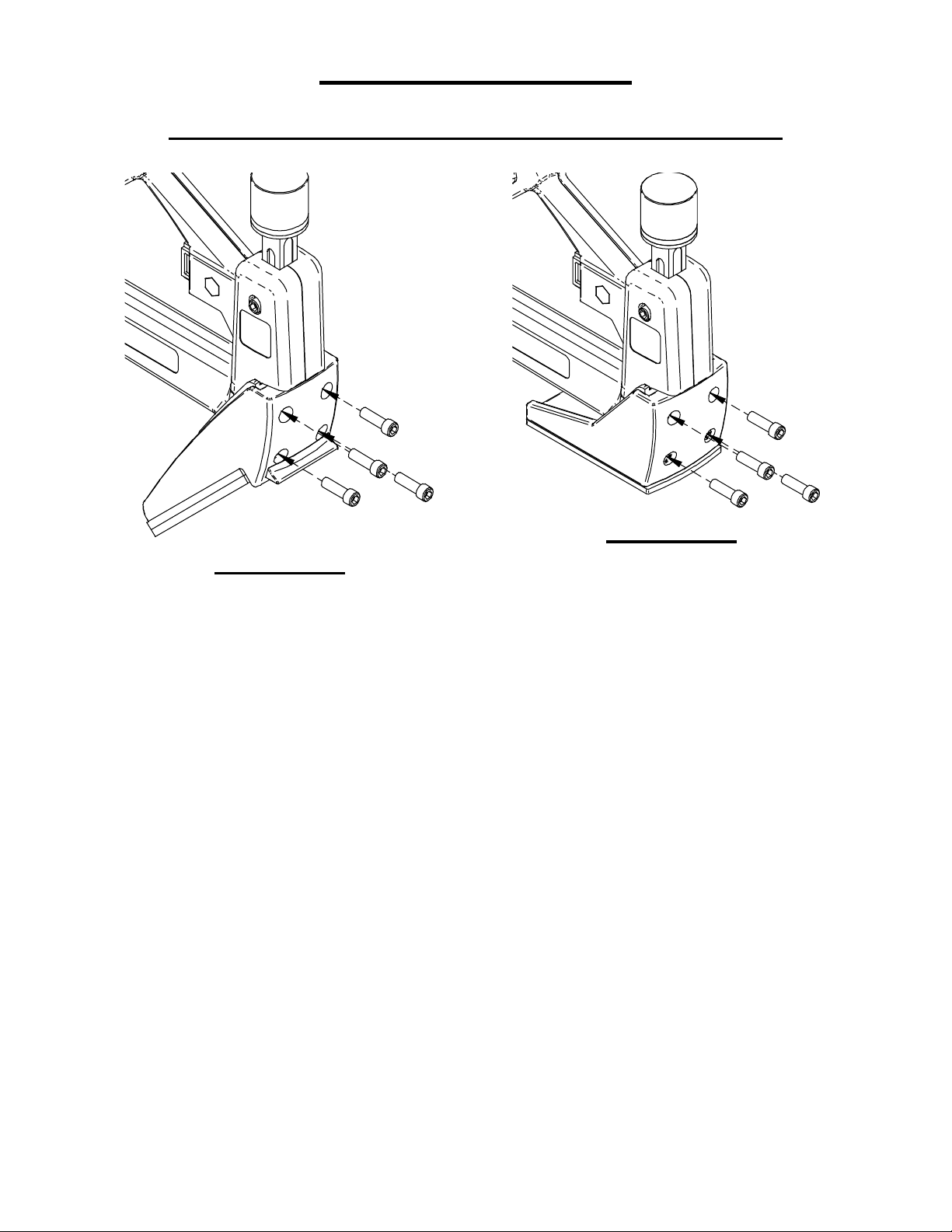
SHOE CHANGING
CONVERSION TO AND FROM FACE NAILING
FIGURE 8
FIGURE 7
Angled Tongue and
Groove Flooring Shoe
Loosen and remove Socket Head Cap Screws (Ref. No. 10) to remove
Shoe & Shoe Base Assembly. Change over from the Angled Tongue
Nailing to Face Nailing Applications or change from Face Nailing to
Angled Tongue Nailing Applications by removing Socket Head Cap
Screws (Ref. No. 10) and re-tightening after changeover.
Face Nailing Shoe
Cat. No. 40225
8
Page 9

NAILING TONGUE AND GROOVE FLOORING
Your Model 402 Nailer is furnished with two (2) Shoe Bases
(Ref. No. 5). When nailing 3/4” thick flooring, both of these bases are
used. When nailing 33/32” thick flooring, only use one (1) Shoe Base
(Ref. No. 5).
1. After squaring the Floor and allowing for expansion as
recommended by the Wood Flooring Industry (NWFA, NOFMA
and MFMA), place the grooved edge of the first row of Flooring
towards the wall on the side of the room from which you are
starting. Nail in place using the Model 402 Nailer with the Face
Shoe installed. (See Shoe Changing Section Pg. 8).
2. After nailing the First (1
groove of the Second (2
st
First (1
) row of Flooring and drive snug using the rubber knob end
of the Porta-Nailer Hammer and nail in place just as the First (1
st
) row of Flooring, (See Figure 8) place the
nd
) row of Flooring over the Tongue of the
st
)
Row of Flooring.
3. Change over to use the Angle Shoe (See Shoe Changing Section Pg.
8), and place the groove of the Third (3
tongue of the Second (2
nd
) row of Flooring and drive snug using the
rd
) row of Flooring over the
rubber knob end of the Porta-Nailer Hammer .
4. Position the Model 402 Nailer with the Tongue Nailing Shoe
rd
Installed on the tongue of the Third (3
) Row of Flooring in the
manner shown in Figure 8. (THE FIELD SHOULD BE NAILED
ONLY THRU THE TONGUE. SEE ILLUSTRATION ON
PAGE 22).
5. Strike the Ram Head (Ref. No. 21) with the metal end of the
Hammer Head to drive the Nail.
6. Continue to strike the Ram Head (Ref. No. 21) until the Ram returns
to its original position. (It usually takes two blows to drive a nail.)
7. If, after striking the Ram Head (Ref. No. 21), the Ram does not
return to its original position, it is a warning that the Nail has not
been completely driven.
8. When the Nail has been completely driven, the Ram will return to its
original position.
9. Be careful not to drive one Nail on top of another. Damage to the
Nailer might result if this should occur.
9
Page 10

10. Slide the Nailer along the tongue of the board to the location at
which you desire to drive the next nail. (8-10 inches is the general
rule of thumb.) Try to get a nail in each Joist.
11. Continue Steps 5-10 until you have completely nailed the board.
12. Repeat Steps 4-11 until all but the last Six (6) Rows of boards have
been nailed in place.
13. Change over to use the Face Nailing Shoe (See Shoe Changing
Section Pg. 8), and install the last Six (6) Rows of Flooring as shown
in Figure 8.
10
Page 11

DISASSEMBLY OF UNIT
Check the Nailer for faulty operation. It can probably be noted at this
time if there are any broken springs or assemblies which do not work
properly or if the machine is jammed.
1. Unhook the Connector (Ref. No. 17) and remove the Pusher (Ref.
No. 20) from the Nail Rail.
2. Back out, but do not remove, the two (2) Ram Stop Screws (Ref.
No. 28) and pull out the Ram (Ref. No. 22), Ram Spring (Ref. No.
26), and Ram Spring Guide (Ref. No. 25). Remove the Driver
Blade (Re f. No. 23) from the Ram.
3. Remove the four (4) Shoe Screws (Ref. No. 10), securing Shoe
(Ref. No. 4) and remove the Shoe from the Nailer. Check the
Wear Plate (Ref. No. 12) and Shear Plate (Ref. No. 13) for wear.
4. Both the Wear Plate (Ref. No. 12) and the Shear Plate (Ref. No.
13) can be lifted off. If the Shear Plate (Ref. No. 13) is tight, pry it
off, but use CAUTION not to damage any of the parts.
5. Turn the Nailer over and remove the Shoulder Screw Nut (Ref. No.
30) from the Shoulder Screw (Ref. No. 29).
6. Remove the Shoulder Screw (Ref. No. 29) and pull the Pawl
Housing Assembly (Ref. No. 47) from the Pawl Housing Cavity
area.
7. Remove the three (3) Body Handle Screws (Ref. No. 37) in the
Handle area and the four (4) Nailer Body Screws (Ref. No. 36) in
the Ram Housing area.
8. Separate the two (2) main Nailer Body Castings (Ref. Nos. 1 & 2)
and lift out the Ram Guide (Ref. No. 27). Check the Ram Stop
Blocks (Ref. No. 35) and the Ram Stop Springs (Ref. No. 34)
positioned by the Ram Stop Screws (Ref. No. 28) for wear.
9. Remove the Nail Rail (Ref. No. 19) from the Casting.
11
Page 12

ASSEMBLY OF UNIT
1. Clean and inspect all parts and check springs for breakage or weak
sections. Check the Nailer Body Castings (Ref. Nos. 1 & 2) for
cracks or worn spots.
2. Insert the Nail Rail (Ref. No. 19) into the Nailer Body Casting
(Ref. No. 1) being sure that the Rail Spring Pin (Ref. No. 18) and
the hole in the Nail Rail line up properly.
3. Insert the Ram Guide (Ref. No. 27) into the Nailer Body Casting
(Ref. No. 1). NOTE: Be sure the Ram Stop Blocks (Ref. No. 35)
are well seated in the Nailer Body Casting recess under the Ram
Guide and that the holes in the Ram Guide will line up with the
two (2) Ram Stop Block Screws (Ref. No. 28).
4. Position the Nailer Body Castings (Ref. Nos. 1 & 2) together;
check to be sure they are lined up properly.
5. Replace the three (3) Body Handle Screws (Ref. No. 37) in the
Handle area and the four (4) Nailer Body Screws (Ref. No. 36) in
the Ram Housing area.
6. Insert the Pawl Housing Assembly (Ref. No. 47) into the Pawl
Housing Cavity area.
7. Insert the Shoulder Screw (Ref. No. 29) thru the Nailer Body
Castings and fasten with the Shoulder Screw Nut (Ref. No.30).
8. Position the Shear Plate (Ref. No. 13) and tap it lightly to seat it on
the Wear Plate / Shear Plate Dowel Pins (Ref. No. 11) and against
the Nailer Body Castings. Position the Wear Plate (Ref. No. 12)
on the same Pins and tap into place against the Shear Plate. (Ref.
No. 13).
9. Secure the Shoe Assembly (Ref. No. 4) with the four (4) Shoe
Screws (Ref. No. 10).
10. Insert the Ram Spring Guide (Ref. No. 25) with the flat end down
and the round notch towards the front. Slide the Ram Spring (Ref.
No. 26) down over the Ram Spring Guide.
11. Lubricate the Ram (Ref. No. 22) lightly with silicone spray or a
similar non-fluid lubricant. Position the Driver Blade (Ref. No.
23) into the recess in the Ram (Ref. No. 22). Slip the entire
assembly into the Ram Guide (Ref. No. 27).
12. Push the Ram down so the Driver Blade (Ref. No. 23) will slide
down between the Wear Plate (Ref. No. 12) and Shear Plate (Ref.
No. 13). Hold the Ram (Ref. No. 22) down and tighten the two (2)
Ram Stop Screws (Ref. No. 28).
12
Page 13
13. Slide the Pusher (Ref. No. 20) into the Nail Rail (Ref. No. 19) and
secure it with the Connector (Ref. No. 17).
14. Check the Nailer for overall operation.
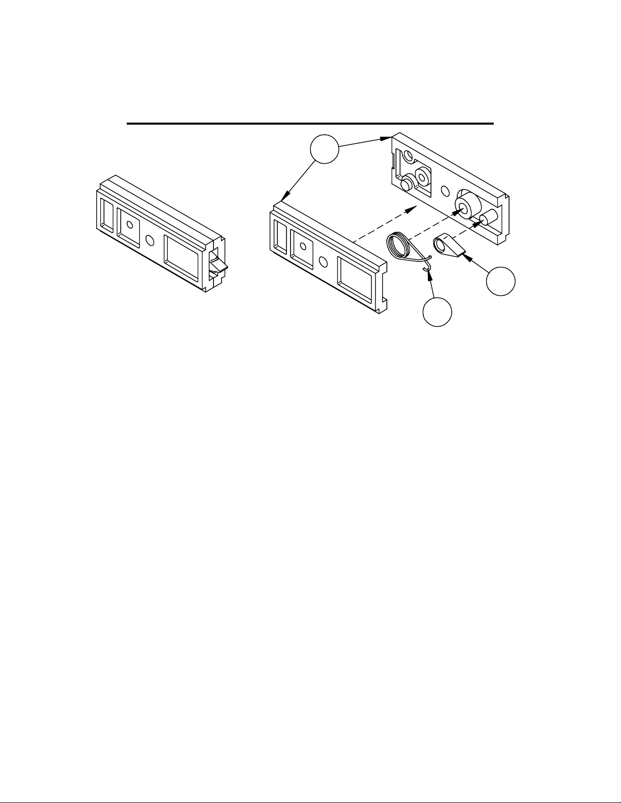
REPLACING THE PAWL & PAWL SPRING
31
33
32
1. Separate the Pawl Housings (Ref. No. 31). Remove the Pawl
Spring (Ref. No. 32) and replace if needed. Remove the Pawl
(Ref. No. 33) and replace if needed. Insert the Pawl and Pawl
Spring into one side of the Pawl Housing (male side with posts).
Position the other Pawl Housing on top of the assembly and
press together.
2. After pressing together, check to make sure the Pawl moves
freely and always returns to the center position.
13
Page 14
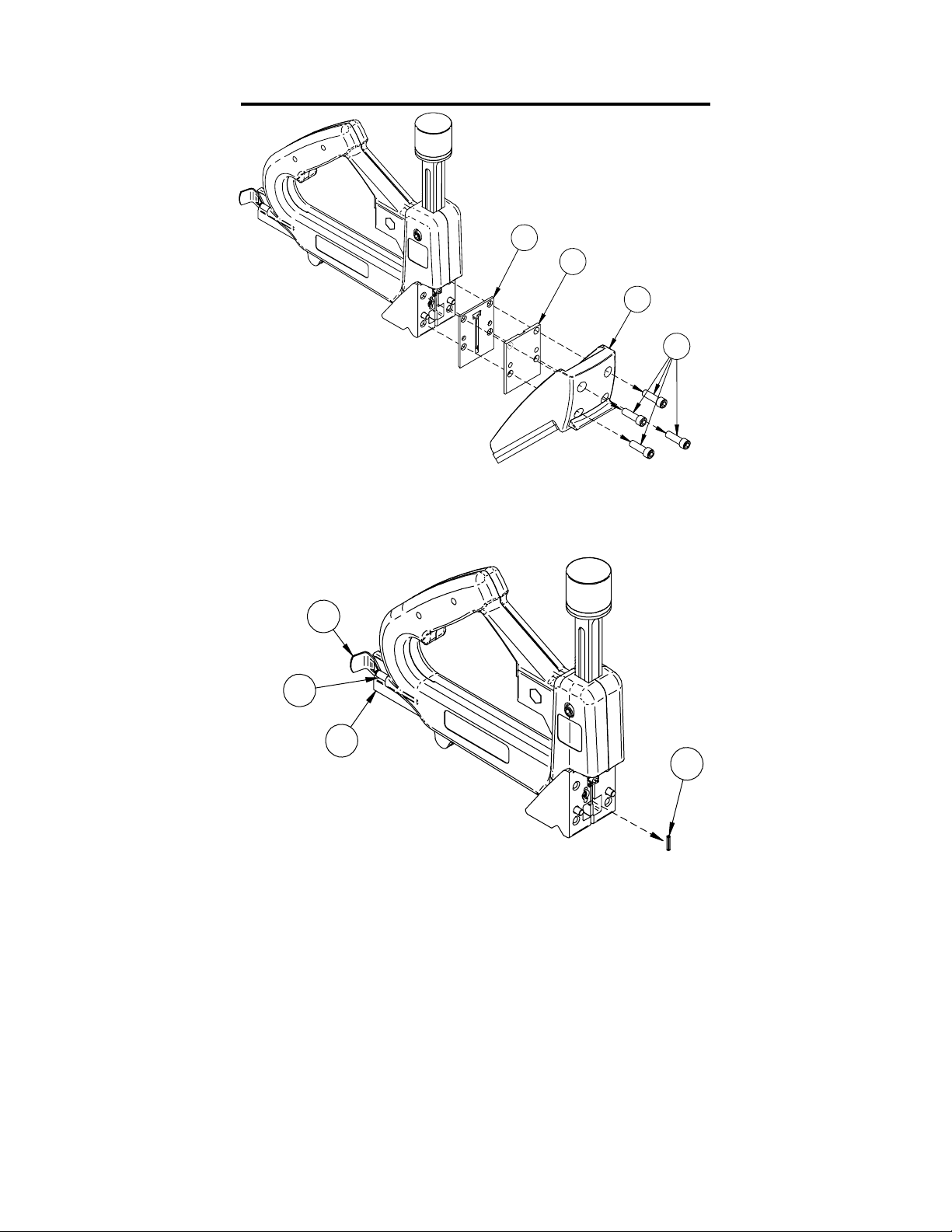
REPLACING THE PUSHER SPRING
13
12
4
10
1. Remove the four (4) Shoe Screws (Ref. No. 10), securing Shoe
(Ref. No. 4) and remove the Shoe from the Nailer. Remove the
Wear Plate (Ref. No. 12) and the Shear Plate (Ref. No. 13).
17
16
20
14
2. Unhook the Connector (Ref. No. 17) from the Pusher (Ref. No.
20) and remove the Pusher. Disconnect the Connector (Ref. No.
17) from the Pusher Spring (Ref. No. 16). Pull the Pusher
Spring out thru the front end of the Pusher Spring Tube (Ref.
No. 15).
14
Page 15
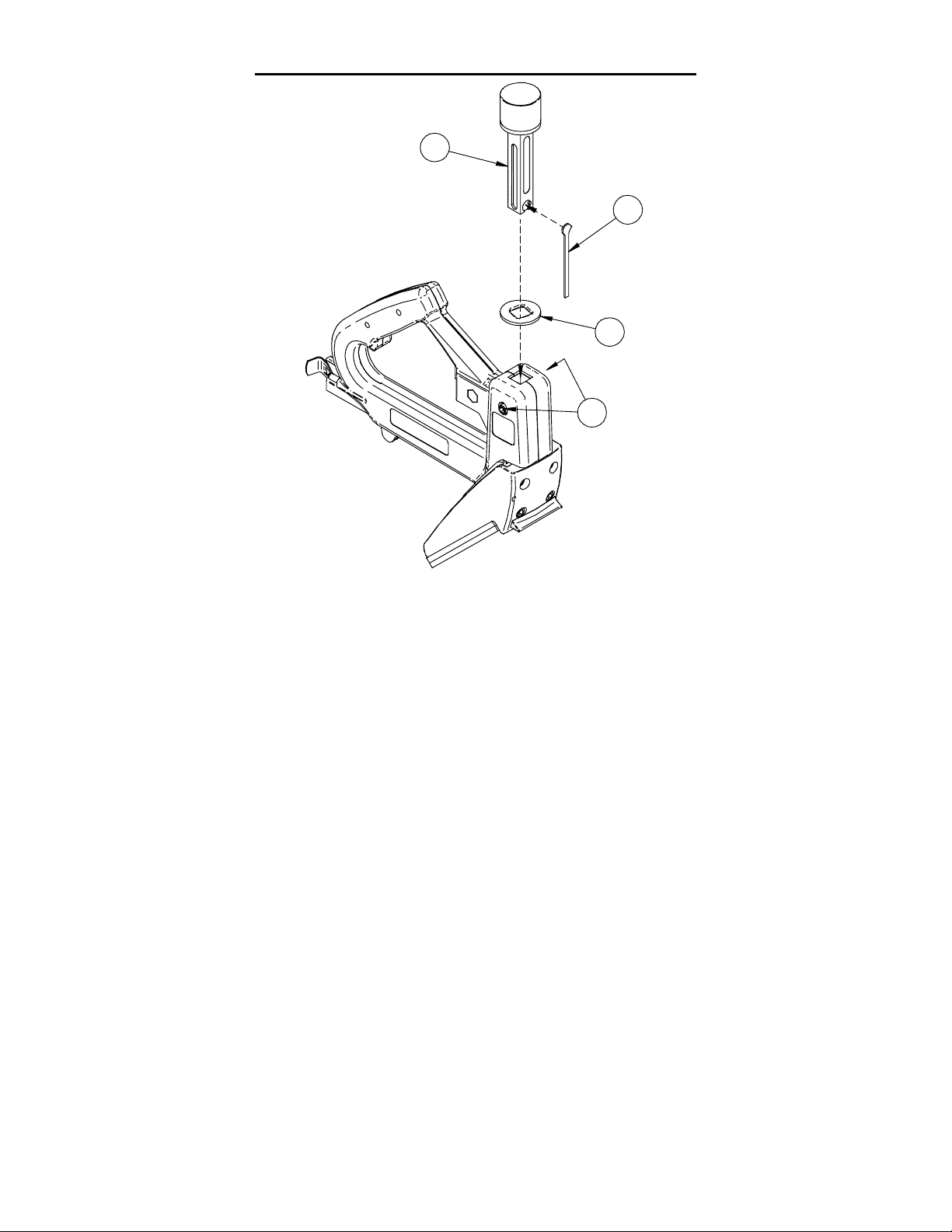
REPLACING THE RAM WASHER
22
23
24
28
1. Loosen, but DO NOT REMOVE, the two (2) Ram Stop Screws
(Ref. No. 28) while holding the Ram (Ref. No. 22) down.
2. After the Ram Stop Screws are loose enough to allow the Ram to
be removed, gently pull out the Ram and Driver Blade (Ref. No.
23).
3. Remove the Driver Blade and slide the worn Ram Washer (Ref.
No. 24) over the Ram to remove it.
4. Slide the replacement Ram Washer over the Ram until it is
positioned under the Ram Cap.
5. Reposition the Driver Blade (Ref. No. 23) into the recess in the
Ram (Ref. No. 22). Slip the entire assembly into the Ram Guide
6. Push the Ram down so the Driver Blade (Ref. No. 23) will slide
down between the Wear Plate and Shear Plate. Hold the Ram
(Ref. No. 22) down and tighten the two (2) Ram Stop Screws
(Ref. No. 28).
15
Page 16
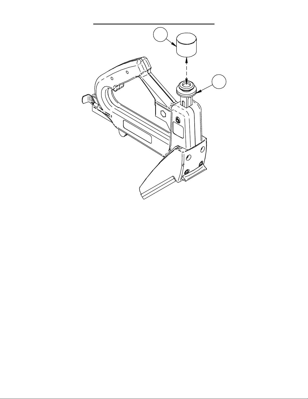
REPLACING THE RAM CAP
21
22
1. To replace the Ram Cap (Ref. No. 21) remove worn Ram Cap
(Ref. No. 21) from the Ram (Ref. No. 22).
2. Use soap and water to aid in applying the Ram Cap (Ref. No. 21)
to the head of the Ram (Ref. No. 22).
GUARANTEE ON RAM IS VOID WHEN USED
WITHOUT THE RAM RUBB ER CAP I N PLACE.
16
Page 17

PROBLEM
OR
TROUBLESHOOTING
QUESTION
Ram comes up
before completing
cycle
Ram does not
come up after
completing
downward cycle.
Ram will not go
all the way down
or up.
CAUSE
Ram(Ref. No. 22)
or Pawl (Ref. No.
33) worn; Pawl
Spring (Ref. No.
32) Broken
Ram Spring (Ref.
No. 26) or Pawl
Spring (Ref. No.
33) broken
Nails Jammed in
Shear Plate (Ref.
No. 13).
CORRECTIVE ACTION
Remove the Shoulder Screw Nut
(Ref. No.30) and the Shoulder
Screw (Ref. No.29). Pull out
Pawl Housing Assembly (Ref.
No. 47) and inspect the Pawl
(Ref. No. 33) and the Pawl
Spring (Ref. No. 32) for wear or
breakage and replace if
necessary. Reinstall and firmly
tighten Shoulder Screw Nut
(Ref. No. 30).
Loosen, but DO NOT
REMOVE, the two (2) Ram
Stop Screws (Ref. No. 28).
Remove the Ram (Ref. No. 22)
and Driver Blade (Ref. No. 23).
Replace the Ram Spring. If the
Ram Spring is not broken,
reverse correction given above.
Refer to the above Corrective
Action for replacing the Pawl
Spring.
Remove the Ram (Ref. No. 22)
and Driver Blade (Ref. No. 23)
as outlined above. Remove the
four (4) Shoe Screws (Ref. No.
10) and Shoe (Ref. No. 4). Lift
off the Wear (Ref. No. 12) Plate
and remove the jammed nails.
Ram will make a
complete cycle
but works hard
Lack of lubrication
and dirt /
contaminate
accumulation
Remove the Ram (Ref. No. 22)
and Driver Blade (Ref. No. 23)
as outlined above. Clean the
Ram and Driver Blade and
lubricate the Ram lightly with a
dry silicone lubricant.
17
Page 18
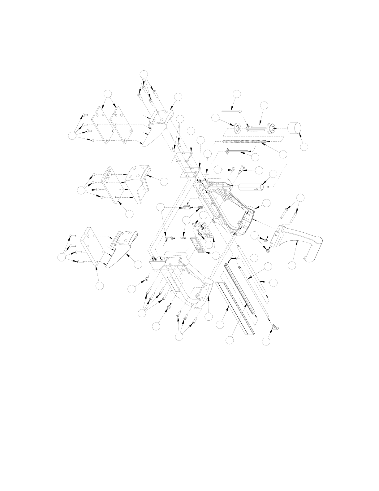
10
5
6
9
8
35
4
11
12
7
34
24
13
14
28
33
32
23
38
25
29
22
21
26
27
38
1
41
40
28
39
36
30
37
31
2
20
19
18
16
17
3
15
18
Page 19

Ref. Part
No.
No. Description
1. 40272 Body – R.H.
2. 40273 Body – L.H.
3. 40061 Extension Handle (Includes #38)
4. 40220 Tongue Nailing Shoe
5. 40153 Tongue Nailing Shoe Base – (2 ea)
6. 2598 Tongue Nailing Shoe Base Screws (4 ea)
7. 40223 Face Shoe
8. 40224 Face Shoe Base
9. 40226 Face Shoe Base Screws (4 ea)
10. 40043 Shoe Screws (4 ea.)
11. 40040 Wear Plate / Shear Plate Dowels (2 ea)
12. 54580 Wear Plate
13. 40170 Shear Plate
14. 53849 Pusher Spring Roll Pin 1/8 x 5/8
15. ------- Pusher Spring Tube (See Ref. No. 48)
16. 40146 Pusher Spring
17. 40093 Connector
18. 40109 Rail Spring Pin 1/8 x 3/8
19. 40151 Rail
20. 40094 Pusher
21. 40030 Rubber Ram Cap
22. 40116 Ram (Includes #’s 21,24,26)
23. 40131 Driver Blade
24. 40052 Ram Washer
25. 40124 Ram Spring Guide
26. 40126 Ram Spring
27. 40245 Ram Guide
19
Page 20

28. 40050 Ram Stop Screws (2 ea)
29. 40241 Shoulder Screw (Includes #30)
30. 301012 Shoulder Screw Nut
31. 2190 Pawl Housing Set
32. 40101 Pawl Spring
33. 40037 Pawl
34. 40115 Ram Stop Springs (2 ea)
35. 40048 Ram Stop Block
36. 40243 Nailer Body Screws (4 ea.)
37. 40244 Body Handle Screws (3 ea.)
38. 1165 Extension Handle Fasteners
39. 40229 Thin Flooring Shoe
40. 40152 Thin Flooring Shoe Base
41. 2600 Thin Flooring Shoe Base Screws (4 ea.)
42. 40221 Tongue Nailing Shoe Assembly
(Includes #’s 4, 5, 6) Not to be used
with Cat. No. 401
43. 40225 Face Shoe Assembly (Includes #’s 7, 8, 9)
Not to be used with Cat. No. 501
44. 40230 Thin Flooring Shoe Assembly (Includes #’s 39,
40, 41) – Not to be used with Cat. No. 401
45. 40008 Hammer (Not Shown)
46. 840080 Spare Parts Package (Not Shown
Includes #’s 24, 26)
47. 2191 Pawl Housing Assembly
(Includes #’s 31, 32, 33)
48. 40097 Pusher Spring Tube Assembly
(Includes #’s 15, 16, 17)
49. 59561 Starter Parts Kit
24, 25, 26, 32, 33)
(Includes #’s 12, 13, 20, 21, 23,
20
Page 21
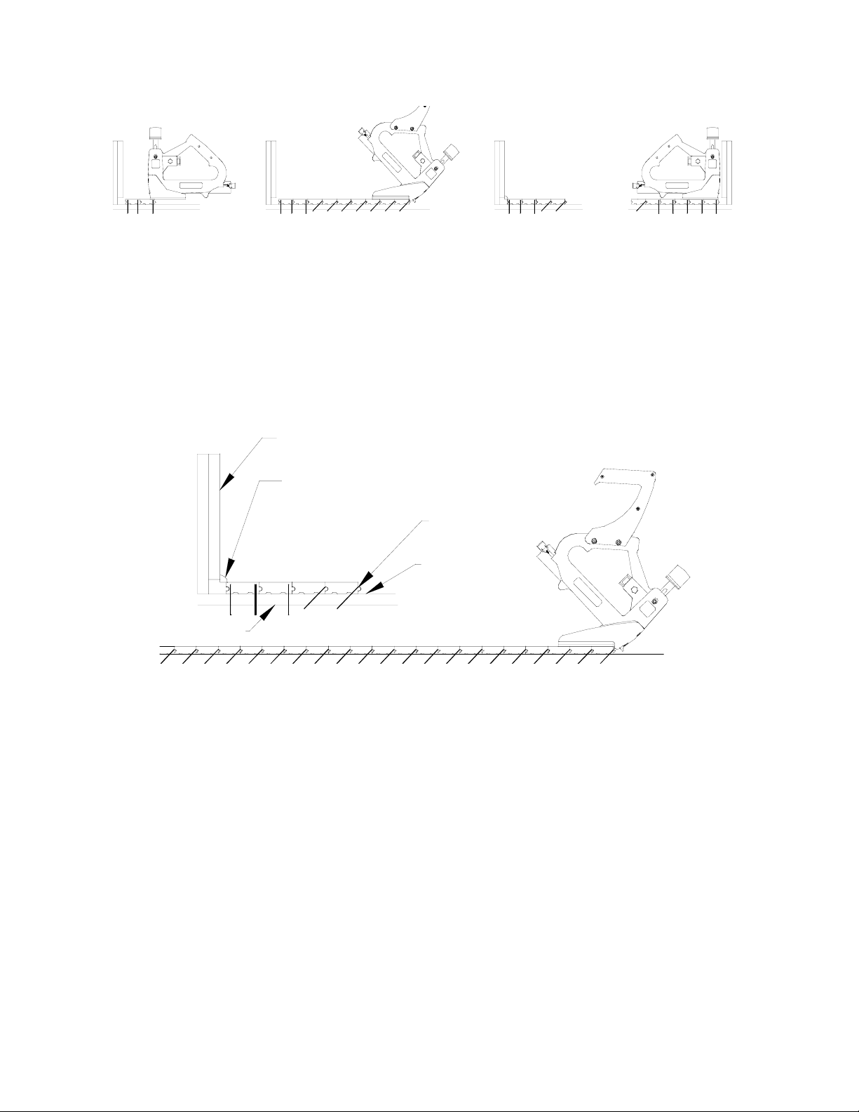
HARDWARE FLOOR INSTALLATION
MADE SIMPLE WITH THE PORTA-NAILER
1. 2. 3. 4.
1. Face Nail the first two courses with the Face Nailing Shoe,
tongue toward the opposite wall.
2. Nail down the field with the Angle Nailing Shoe. Always nail
in the Tongue, not the Groove.
3. Smooth and accurate secret finish.
4. At the opposite wall, Face Nail the remaining six strips.
Base bo ar d
Rug Mould
Porta-Nail
Hardwood Floor
Sub-Floor
Building
Paper
BRIEF INSTRUCTIONS FOR USE OF
THE PORTA-NAILER SYSTEM
Always wear safety glasses AND safety shoes.
OPERATION FOR USE OF THE
PORTA-NAILER SYSTEM
1. This tool is designed to properly seat the nail with one or SEVERAL
blows of the Hammer.
2. Tap the flooring into place with the non-marring rubber side of the
Hammer.
3. Strike the Rubber Cap of the Nailer with the iron side of the
Hammer.
4. The first two strips of flooring and the last six MUST be nailed with
the Face Nailing Shoe installed on the Porta-Nailer.
21
Page 22
5. The Porta-Nailer MUST be held firmly, but not over-tightly in the
hand so that the Porta-Nailer rests perfectly flat on the floor with the
lip of the shoe hanging over and against the edge of the strip being
nailed. As an aid to holding it flat against the floor, rest the toe of
your shoe on the rear of the Porta-Nailer Shoe.
6. DO NOT OVERPOWER THE PORTA-NAILER – Strike it firmly
but NOT HARD, and then strike it again until the Ram returns. The
Ram does not return until the nail is properly seated.
7. Do not attempt to nail the last six strips of flooring down with the
Angled Shoe installed. Switch and install the Face Nailing Shoe.
The Porta-Nailer system is user-friendly and following these simple
instructions, will insure a perfect hardwood flooring installation.
USE OF THE
BUILDING
PAPER
TONGUE & GROOVE
FLOORING
SUBFLOOR
JOIST
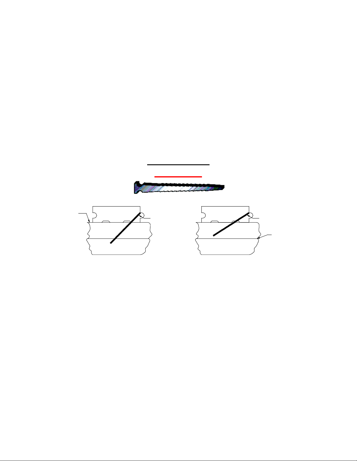
The Porta-Nail is 2” long and the
PORTA-NAILER with the
standard shoe drives the nail into
the tongue and groove flooring at a
45-degree angle. The orientation of
the nail is as depicted in wood floor
joist construction.
Porta-Nail
PORTA-NAIL
In applications where tongue and
groove flooring is laid over
concrete, the Accessory Shoe
42626 Shoe Base is used to
increase the angle so that the Nail
will not protrude through 3/4”
plywood underlayment.
TONGUE & GROOVE
FLOORING
CONCRETE
3/4" PLYWOOD
PORTA-NAIL
MOIST URE
BARRIER
22
Page 23
ACCESSORIES (Pg. 23 & 24)
The testing of this tool has been accomplished with the following
accessories. For safest operation, it is recommended that only these
accessories be used with this product. WARNING – Since accessories
other than those listed have not been tested with this product, use of such
accessories could be hazardous.
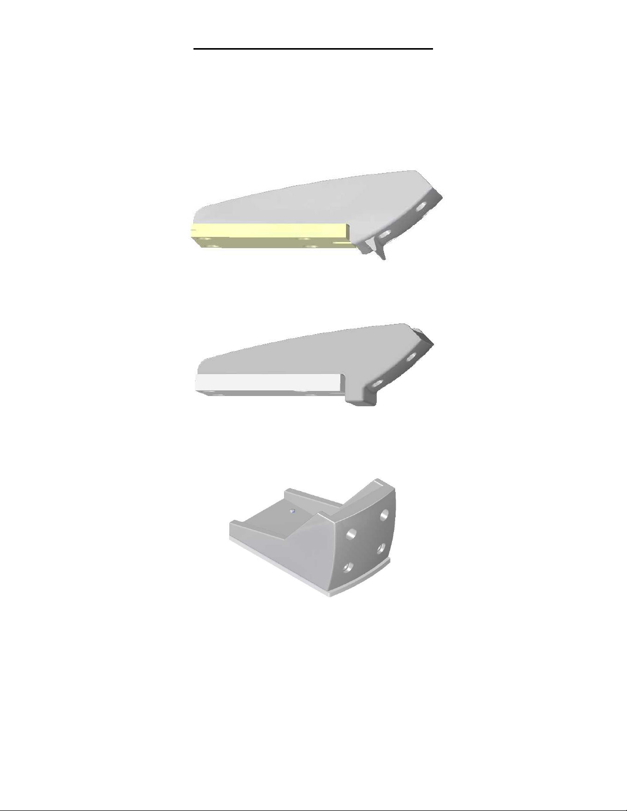
Cat. No. 40221
Tongue Nailing Shoe for 5/8” – 33/32” Flooring.
Cat. No. 40230
Tongue Nailing Shoe for 3/8” – 9/16” Flooring.
Cat. No. 40225
Face Nailing Shoe
23
Page 24
ACCESSORIES cont’d.
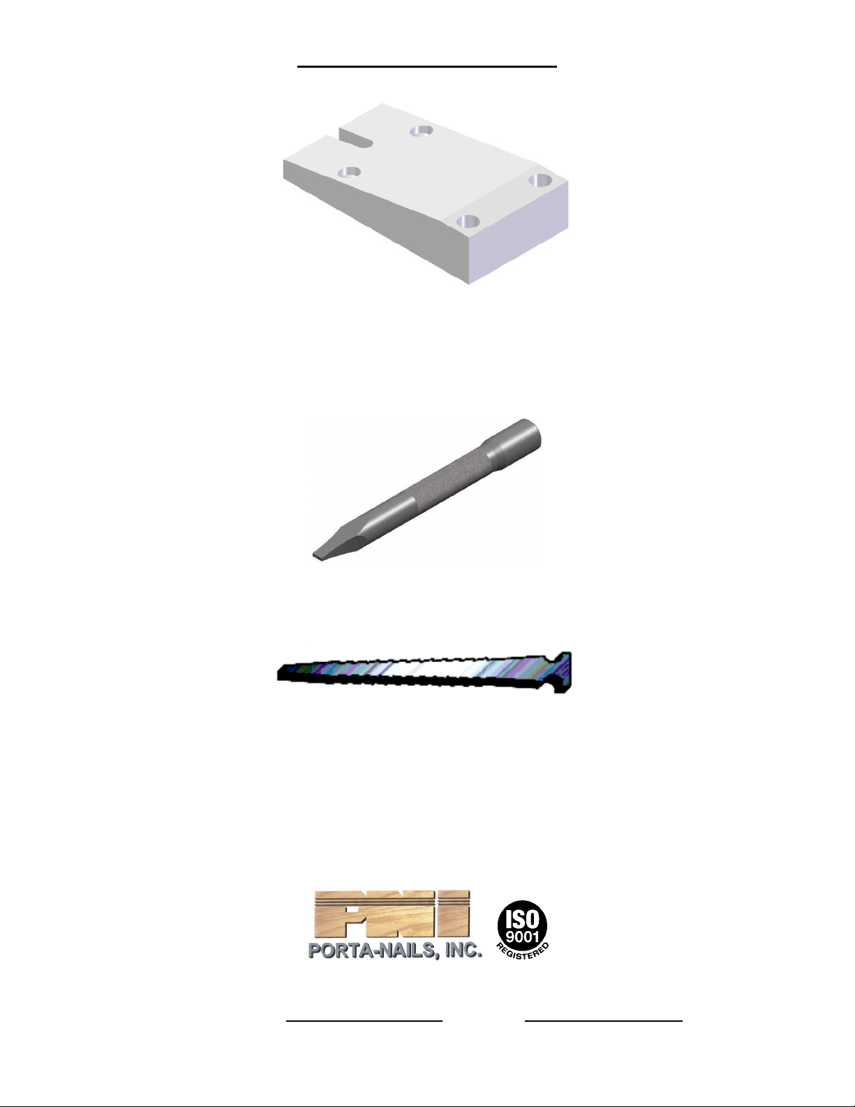
Cat. No. 42626
Angled Shoe Base for Nailing 3/4” Flooring
over 3/4” Plywood over Concrete
Cat. No. 42620
Porta-Nail Set Tool
Cat. No. 42623
Porta-Nail - 10 Boxes of 1000 2” Nails
Cat. No. 40253
Molded Carrying Case (not shown)
PO Box 1257, Wilmington, NC 28402
910-762-6334 • 800-634-9281 • FAX: 910-763-8650
HOME PAGE: www.porta-nails.com
E-MAIL: [email protected]
24
 Loading...