

Page 1
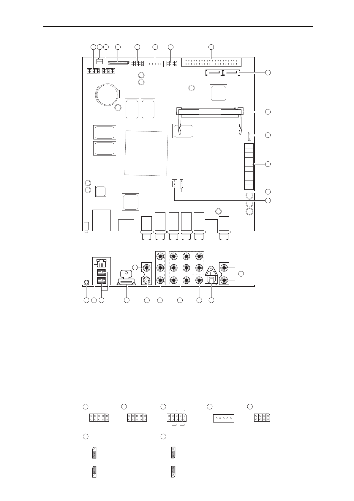
Popcorn Hour B-110 Motherboard Layout Diagram
1 2
3 4 5 6
7
J44
8
9
10
J31
11
12
13
14
19
15 18 20 22 23 2421
16 17
1. UART1
2. Reset button
3. UART0
4. LCD connector
*
5. LED, Power & Reset Switch connectors
6. FIP connector
*
7. USB connector
8. IDE connector
9. SATA connectors
10. mini-PCI slot
*
11. Boot up option (J31)
12. ATX main power supply connector
13. CPU fan voltage selector (J44)
Note : LCD, FIP & mini-PCI WiFi modules will be available as upgrade options from Popcorn Hour in the future.
*
1
GND
UART1
VCC5VU1_RXD
U1_TXD
J38
3
VCC5VU0_RXD
GND
U0_TXD
UART0
5 6
SW RST
J2
- +
- +
SW PWR
14. CPU Fan
15. IR jack
16. Ethernet port
17. USB ports
18. HDMI
19. Composite Video
20. S-Video
21. Component Video
22. 7.1 Analog Audio
23. Co-axial S/PDIF
24. Optical S/PDIF
25. Analog Stereo
LED HDD
- +
J7
- +
LED PWR
F.I.P.
GND I.R. CLK CS DATA
11 13
J31
Auto boot up with ATX power supply
GND
J44
5V
Use 5V for CPU fan
25
7
GND D+ D- +5V
GND D+ D- +5V
NC
Manually boot up with Power Switch
12V
Use 12V for CPU fan
 Loading...