

Page 1
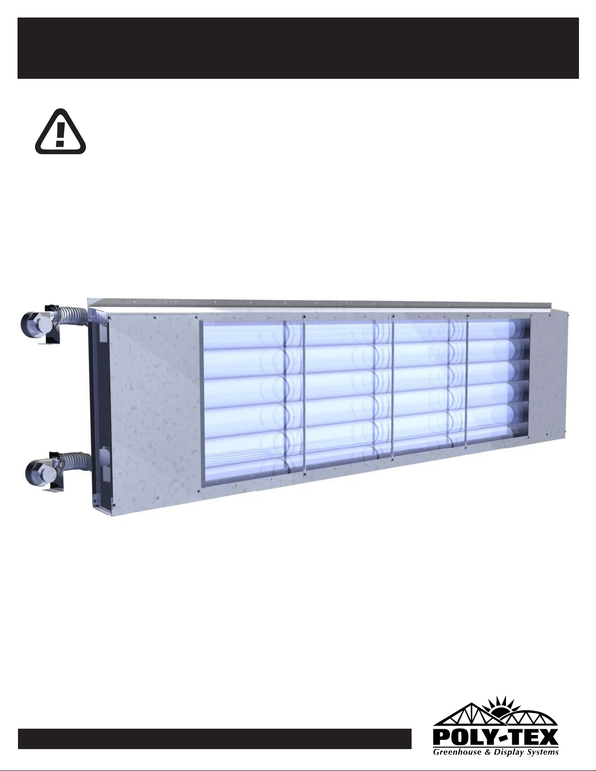
Poly-Vent
ASSEMBLY INSTRUCTIONS
IMPORTANT
Please read these instructions carefully before you start to
assemble this vent system. Save these instructions for future reference.
PolyVent v1.0.
0
Page 2
27725 Danville Avenue
P.O. Box 458
Castle Rock, MN 55010
(651) 463-7009
(651) 463-2479 fax
www.poly-tex.com
U.S. & Canada Toll Free
800-852-3443
Page 3
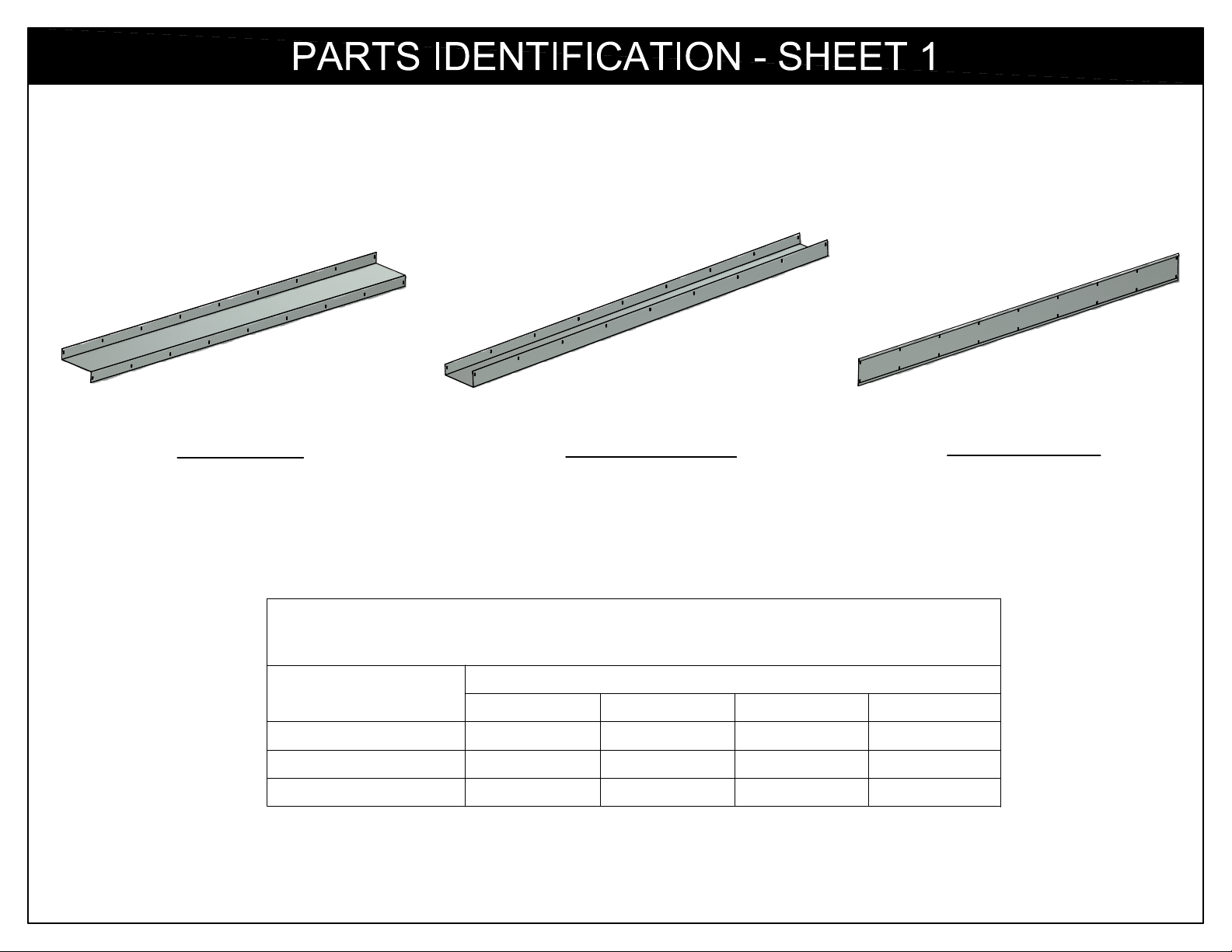
NOTE: PARTS AND PART NUMBERS BELOW COVER ALL LENGTHS OF POLY-VENT SYSTEMS. SOME WILL NOT APPLY
TO YOUR SPECIFIC SYSTEM. PLEASE CONSULT YOUR PICKING TICKET FOR A COMPLETE LIST OF PARTS
AND QUANTITIES FOR YOUR SPECIFIC POLY-VENT SYSTEM.
TOP GUTTER
(8FT LONG GUTTER SHOWN)
Component
Top Gutter
Bottom Gutter
Backer Plate
8 FT LENGTHS ARE THE STANDARD. 6 FT, 4 FT, AND 2 FT LENGTHS ARE ONLY
USED TO MAKE UP THE LENGTHS OF RUNS THAT ARE NOT AT 8 FT MULTIPLES.
BOTTOM GUTTER
(8FT LONG GUTTER SHOWN)
LENGTH RELATED COMPONENTS
(Lengths listed are nominal, actual length is 1" longer)
Part Number
8ft Long
PV6000
PV6001
PV6002
6ft Long
PV6019
PV6022
PV6025
4ft Long
PV6020
PV6023
PV6026
2ft Long
PV6021
PV6024
PV6027
BACKER PLATE
(8FT LONG BACKER SHOWN)
3
Page 4
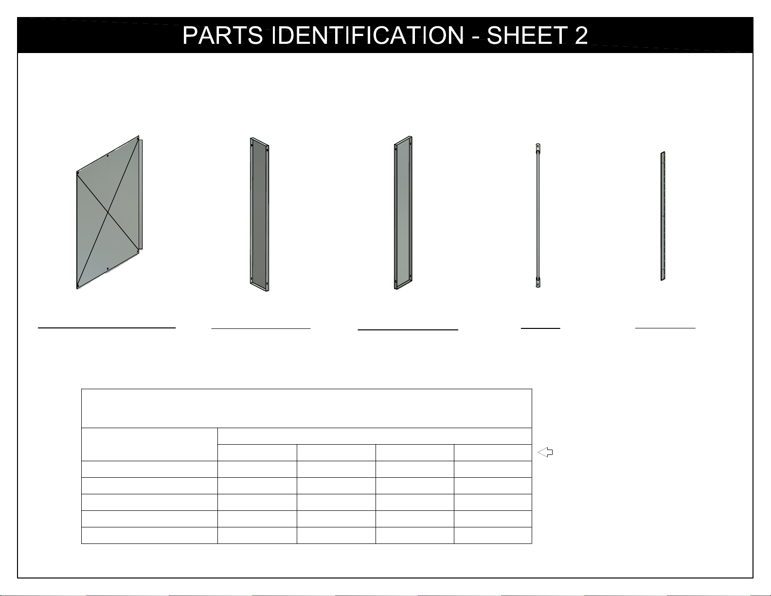
NOTE: PARTS AND PART NUMBERS BELOW COVER ALL HEIGHTS OF POLY-VENT SYSTEMS. SOME WILL NOT APPLY
TO YOUR SPECIFIC SYSTEM. PLEASE CONSULT YOUR PICKING TICKET FOR A COMPLETE LIST OF PARTS
AND QUANTITIES FOR YOUR SPECIFIC POLY-VENT SYSTEM.
FRONT & REAR PANEL
(4FT PANEL SHOWN)
(Lengths listed are nominal Poly-Vent heights, actual heights vary)
Component
Front & Back Panels
End Panels (LH)
End Panels (RH)
Guides
Side Clips
END PANEL (LH)
(4FT END PANEL SHOWN)
END PANEL (RH)
(4FT END PANEL SHOWN)
HEIGHT RELATED COMPONENTS
Part Number
2ft 3ft 4ft 5ft
PV6011
PV6003
PV6004
PV6015
PV4002
PV6012
PV6005
PV6006
PV6016
PV4003
PV6013
PV6007
PV6008
PV6017
PV4004
GUIDE
(4FT GUIDE SHOWN)
PV6014
PV6009
PV6010
PV6018
PV4005
SIDE CLIP
(4FT SIDE CLIP SHOWN)
Nominal Poly-Vent Height
4
Page 5
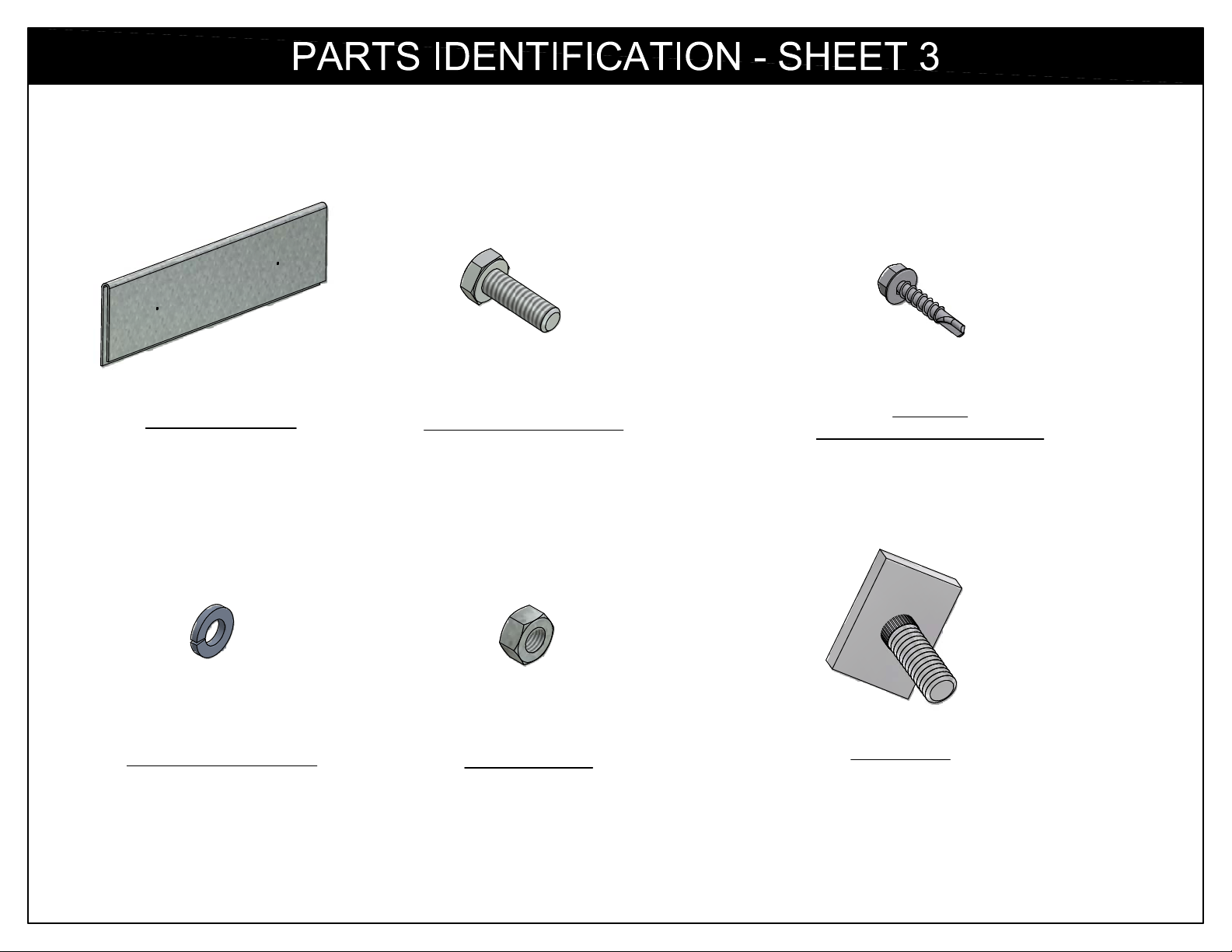
4-1/2" END CLIP
PV4001
1/4" x 3/4" HEX BOLT
NB1840
#12 x 1"
SELF-DRILLING SCREW
NB1804
1/4" LOCK WASHER
NB1860
1/4" HEX NUT
NB1870
STOP TAB
FT2570
5
Page 6
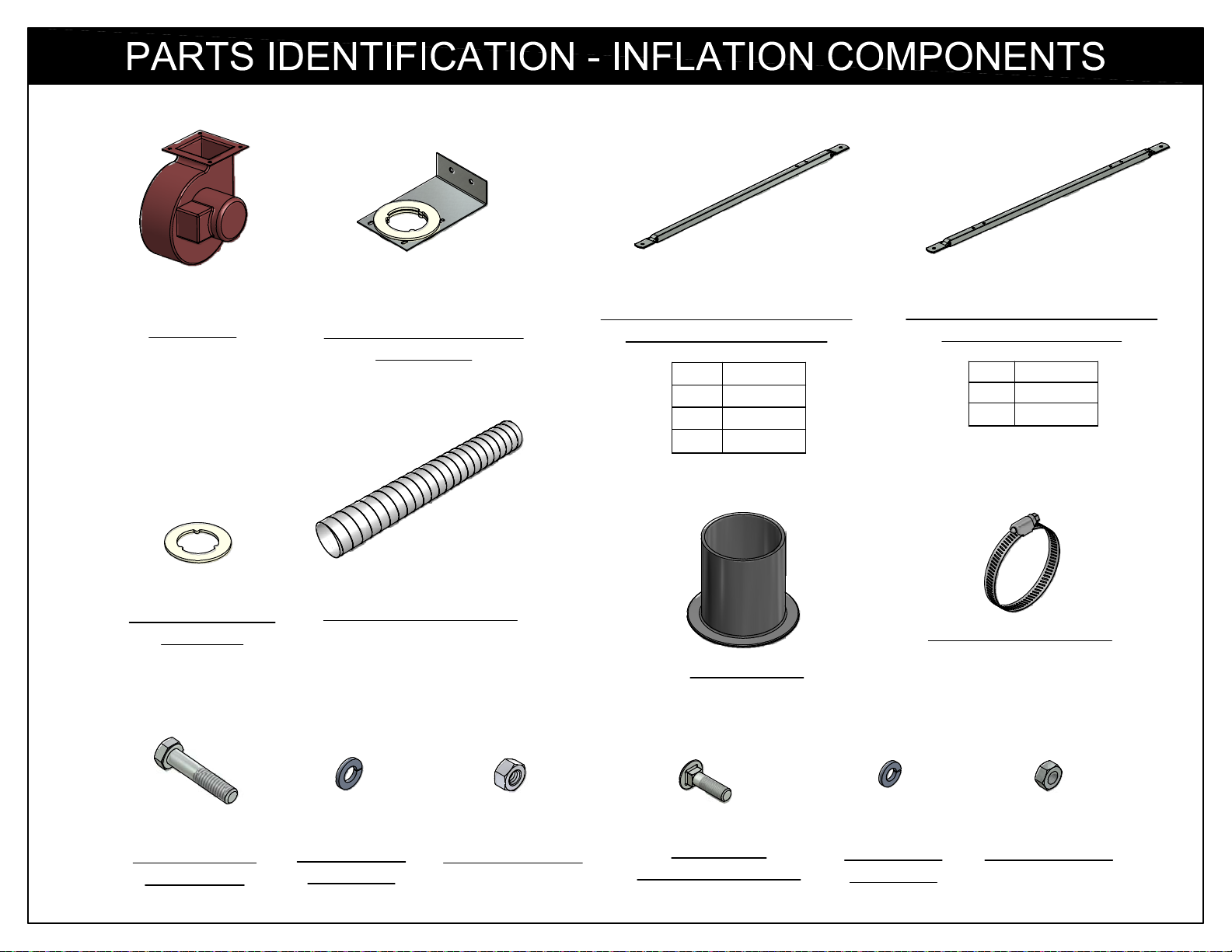
BLOWER
PT2448
BLOWER MOUNTING
BRACKET
PT2409
MOTOR MOUNT BRACKET
PVII (SINGLE STAGE)
2FT PV6028
3FT PV6029
4FT PV6030
5FT PV6031
MOTOR MOUNT BRACKET
PVIII (TWO STAGE)
3FT PV6032
4FT PV6033
5FT PV6034
AIR TRANSFER
GASKET
PT2436
5/16" x 1-1/2"
HEX BOLT
NB1846
3" x 5' FLEX TUBING
PT2437
5/16" LOCK
5/16" HEX NUT
WASHER
NB1862
NB1872
#3 PV PLUG
PK5086
1/4" x 3/4"
CARRIAGE BOLT
NB1820
3.25" HOSE CLAMP
1/4" LOCK
WASHER
NB1860
PT2420
1/4" HEX NUT
NB1870
6
Page 7
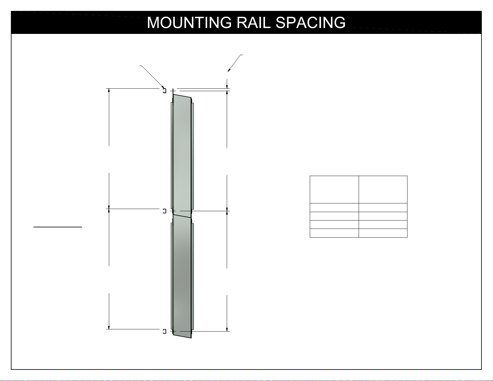
ROLL-FORMED RAIL
TOP OF MOUNTING
RAIL TO CENTERLINE
OF FASTENERS
13/16"
END VIEW
"A"
TOP OF
MOUNTING
RAIL
"A"
TOP OF
MOUNTING
RAIL
"A"
CENTERLINE
OF
FASTENERS
"A"
CENTERLINE
OF
FASTENERS
NOMINAL
POLY-VENT
HEIGHT
2 FT
3 FT
4 FT
5 FT
DISTANCE
"A"
19"
31"
43"
55"
Poly-Vent is mounted to roll-formed rails. The spacing
is the same for either single or stacked applications.
See the chart above to determine the correct spacing
for your Poly-Vent system.
7
Page 8
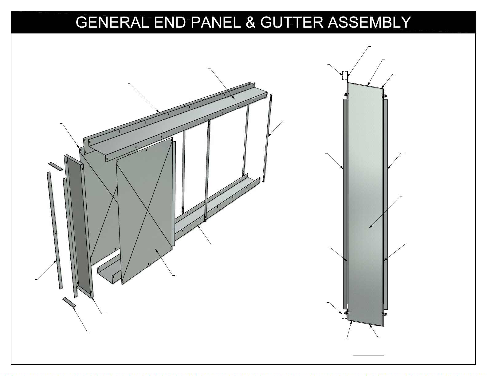
BACKER PLATE
BACK
PANEL
BACKER PLATE
TOP GUTTER
ROLL FORM RAIL
GUIDE
BACK
PANEL
4-1/2" END CLIP
TOP GUTTER
FRONT
PANEL
END PANEL
SIDE
CLIP
4-1/2" END CLIP
P:\ACAD2\MANUALS\POLY-VENT\PG 8 GENERAL PART ORIENTATION.idw
END PANEL
BOTTOM GUTTER
FRONT PANEL
SIDE CLIP
ROLL FORM RAIL
BOTTOM GUTTER
SIDE CLIP
4-1/2" END CLIP
END VIEW
8
Page 9
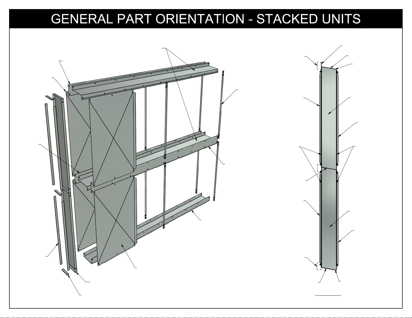
BACK
PANEL
BACKER PLATE
TOP GUTTER
ROLL FORM RAIL
BACKER PLATE
4-1/2" END CLIP
TOP GUTTER
BACKER
PLATE
GUIDE
BACKER PLATE
BOTTOM GUTTER
REAR
PANEL
SIDE CLIP
4-1/2" END CLIP
REAR
PANEL
END PANEL
FRONT
PANEL
SIDE CLIP
END PANEL
FRONT
PANEL
SIDE
CLIP
END PANEL
4-1/2" END CLIP
FRONT PANEL
ROLL FORM RAIL
4-1/2" END CLIP
BOTTOM GUTTER
END VIEW
9
Page 10
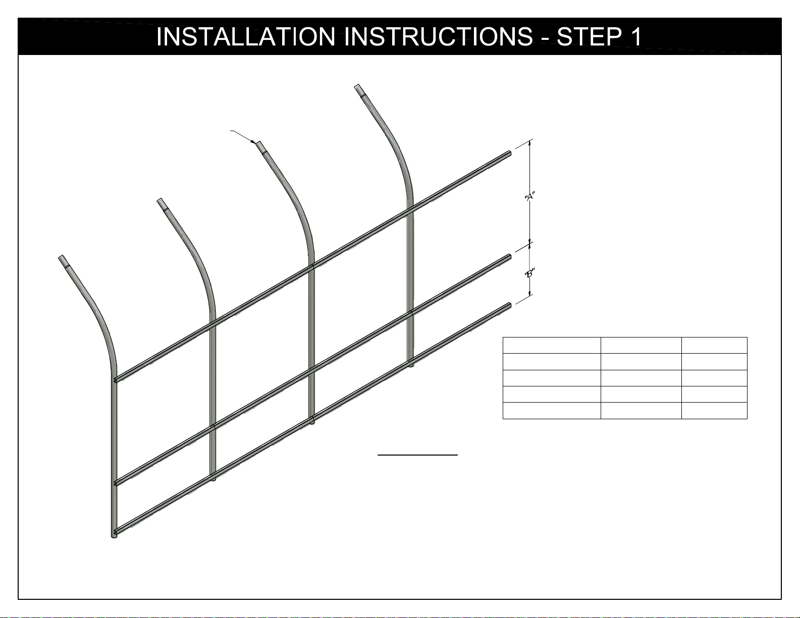
NEW OR
EXISTING
FRAME
Nominal Poly-Vent
2 ft
Distance "A" Distance "B"
19" 50-1/2"
3 ft 31" 38-1/2"
4 ft
5 ft
43" 26-1/2"
55"
INSTRUCTIONS:
1A. MATCH DIMENSIONS WITH THE APPROPRIATE NOMINAL
POLY-VENT HEIGHT.
14-1/2"
10
Page 11
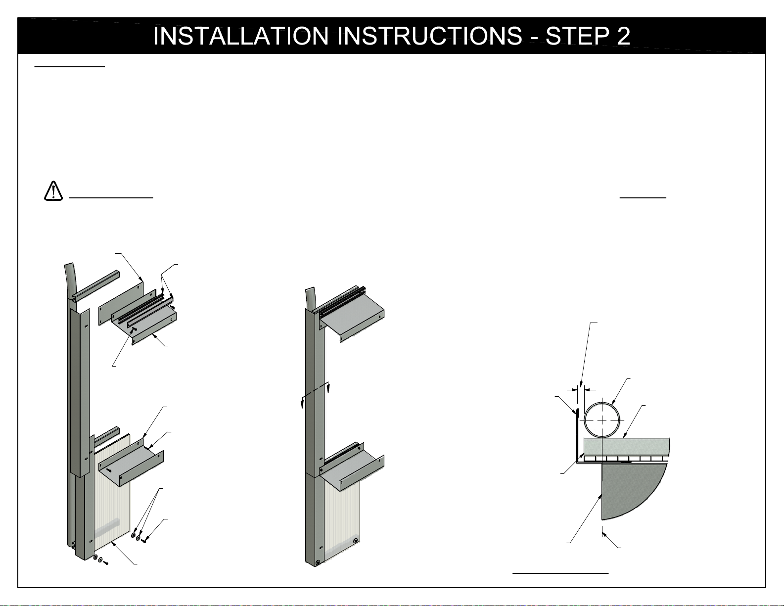
INSTRUCTIONS:
2A. INSTALL THE "L" FLASHING TO ACT AS A CORNER FLASHING COVERING THE STRUCTURED SHEET SKIRT AND FILLER FOR THE ROLLFORM RAILS.
MOUNT THE SKIRTING AND THE LOWER "L" FLASHING FIRST USING THE #12 x 1 1/2" SELF DRILLING SCREWS AND THE NEOPRENE WASHERS
ATTACHING THEM TO THE BOTTOM ROLLFORM RAIL.
2B. MOUNT TOP GUTTER, BACKER PLATE, AND "L" FLASHING TO TOP RAIL USING #12 x 1" SELF DRILLING SCREWS. MAKE SURE THE TOP "L" FLASHING
OVERLAPS THE BOTTOM "L" FLASHING. HEM OF BACKER PLATE SHOULD FACE MOUNTING RAILS. THE TOP EDGE OF THE TOP GUTTER, BACKER
PLATE, AND EDGE OF THE "L" FLASHING SHOULD BE FLUSH WITH THE TOP OF THE MOUNTING RAIL. IF POLY FASTENER IS BEING USED, IT SHOULD
BE MOUNTED AT THE SAME TIME USING THE SAME FASTENERS.
HINT: WELDER VISE GRIPS MAY BE USEFUL TO HOLD COMPONENTS WHILE SCREWS ARE BEING INSTALLED.
IMPORTANT NOTE: IF A POLY FASTENER IS BEING USED, IT IS CRITICAL THAT YOU USE AN APPROPRIATE FASTENER EVERY 12 INCHES.
2C. MOUNT BOTTOM GUTTER TO CENTER RAIL. DO NOT USE THE FIRST THREE MOUNTING HOLES. THESE WILL BE USED IN STEP 3 TO MOUNT THE REAR
PANEL. SKIRTING (IF USED) SHOULD BE MOUNTED BETWEEN THE BOTTOM GUTTER AND THE RAILS. THE TOP EDGE OF THE GUTTER (AND SKIRTING)
SHOULD BE FLUSH WITH THE TOP OF THE CENTER MOUNTING RAIL.
BACKER PLATE
WIGGLE-WIRE BASE (FOR POLY ROOF)
"U" PROFILE (FOR STRUCTURED SHEET ROOF)
TOP GUTTER
#12 x 1" SELFDRILLING SCREW
BOTTOM GUTTER
#12 x 1-1/2" SELFDRILLING SCREW
FLAT WASHER WITH
NEOPRENE BACKING
#12 x 1-1/2" SELFDRILLING SCREW
STRUCTURED SHEET
SKIRTING
- OR -
LEAVE A 3/8" GAP BETWEEN
THE CORNER HOOP AND THE
FLASHING IF YOUR END WALL
IS TO BE COVERED WITH
POLYCARBONATE STRUCTURED
SHEETING.
CORNER HOOP
A
"L" FLASHING
A
3/8"
ROLL-FORMED
RAILS
ROLL-FORMED RAILS
AND SKIRTING SHOULD
BE FLUSH WITH OUTSIDE
OF CORNER HOOP
EDGE OF TOP & BOTTOM
TOP & BOTTOM GUTTERS
GUTTERS SHOULD BE
MOUNTED IN LINE WITH
THE CENTER LINE OF THE
SECTION A-A
CORNER HOOP
11
Page 12
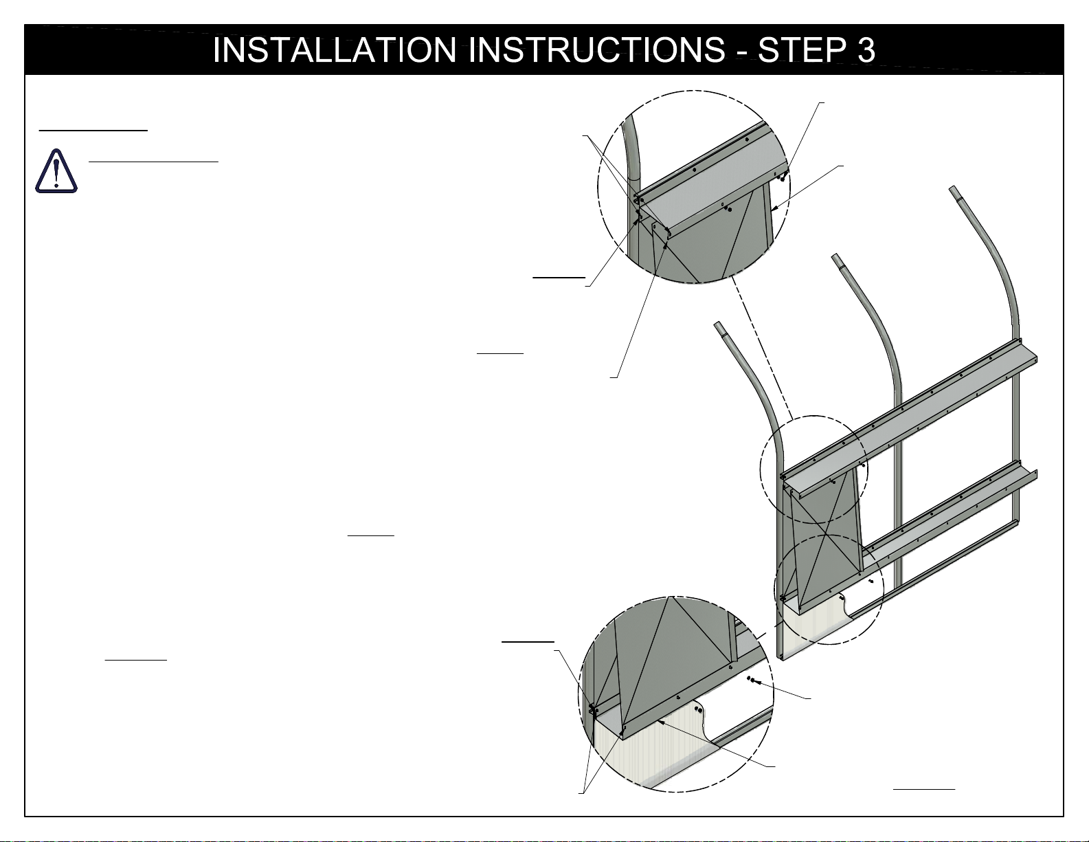
INSTRUCTIONS:
IMPORTANT NOTE: ALL FASTENERS MUST BE INSTALLED
WITH THE BOLT HEAD ON THE INSIDE OF THE POLY-VENT
FRAME TO PREVENT DAMAGE TO THE POLY-VENT TUBES.
3A. INSTALL THE REAR PANEL. THE TOP OF THE
REAR PANEL MOUNTS OUTSIDE OF THE
BACKER PLATE TOWARDS THE INSIDE OF THE
STRUCTURE ON THE TOP. SLIDE THE BOTTOM
OF THE REAR PANEL BETWEEN THE BOTTOM
GUTTER AND THE RAIL (OR THE SKIRTING IF
SKIRTING IS USED). MOUNT THE TOP OF THE
PANEL FIRST, USING HARDWARE PROVIDED.
DO NOT USE THE FIRST MOUNTING HOLE. IT
WILL BE USED LATER TO MOUNT THE END
PANEL. ONLY FINGER TIGHTEN HARDWARE
AT THIS POINT.
3B. MOUNT THE BOTTOM OF THE REAR PANEL. DO
NOT USE THE FIRST MOUNTING HOLE. IT WILL BE
USED LATER TO MOUNT THE END PANEL.
3C. INSTALL FRONT PANEL. MOUNT THE TOP OF THE
PANEL FIRST USING HARDWARE PROVIDED.
MOUNT THE TOP OF THE PANEL ON THE INSIDE OF
THE TOP GUTTER'S FRONT FLANGE. DO NOT USE
THE FIRST MOUNTING HOLE. IT WILL BE USED
LATER TO MOUNT THE END PANEL. ONLY FINGER
TIGHTEN HARDWARE AT THIS POINT.
DO NOT USE FIRST
MOUNTING HOLE AT
THIS POINT.
REAR PANEL
MOUNTS BEHIND
BACKER PLATE
FRONT PANEL
MOUNTS ON THE
INSIDE OF THE TOP
GUTTER'S FRONT
FLANGE
1/4" LOCK WASHER
1/4" HEX NUT
1/4" x 3/4" HEX BOLT (INSIDE)
FLARED EDGE
FLARES AWAY
FROM THE
POLY- VENT
FILM ON BOTH
FRONT AND
REAR PANELS.
3D. MOUNT THE BOTTOM OF THE FRONT PANEL. THE
BOTTOM EDGE OF THE FRONT PANEL MOUNTS TO
THE OUTSIDE OF THE BOTTOM GUTTER. DO NOT
USE THE FIRST MOUNTING HOLE. IT WILL BE USED
LATER TO MOUNT THE END PANEL. ONLY FINGER
TIGHTEN HARDWARE AT THIS POINT.
DO NOT USE FIRST MOUNTING
REAR PANEL
MOUNTS BEHIND
BOTTOM GUTTER.
HOLE AT THIS POINT.
1/4" LOCK WASHER
1/4" HEX NUT
1/4" x 3/4" HEX BOLT (INSIDE)
BOTTOM EDGE OF FRONT PANEL
MOUNTS TO THE OUTSIDE OF THE
BOTTOM GUTTER.
12
Page 13
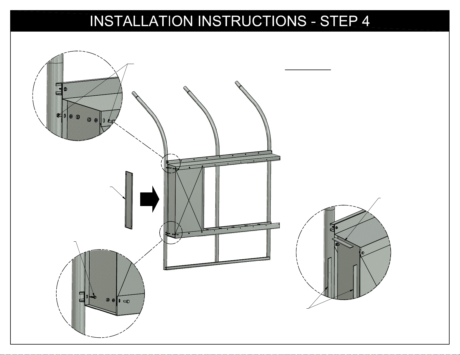
END PANEL
1/4" x 3/4" HEX BOLT
1/4" LOCK WASHER
1/4" HEX NUT
INSTRUCTIONS:
4A. INSTALL END PANEL. MAKE SURE YOU
ARE USING THE CORRECT PANEL (LEFT
HAND OR RIGHT HAND).
4B. AFTER END PANEL IS PROPERLY FITTED
INTO POSITION, ALL HARDWARE HOLDING
FRONT, BACK, AND END PANELS MAY BE
TIGHTENED.
4C. INSTALL SIDE CLIPS AND 4-1/2" END CLIPS
OVER EDGES OF END PANEL, FRONT
PANEL, REAR PANEL, TOP AND BOTTOM
GUTTERS AS SHOWN BELOW.
4-1/2" END CLIP
(TOP AND BOTTOM)
#12 x 1" SELF
DRILLING SCREW
SIDE CLIPS
13
Page 14
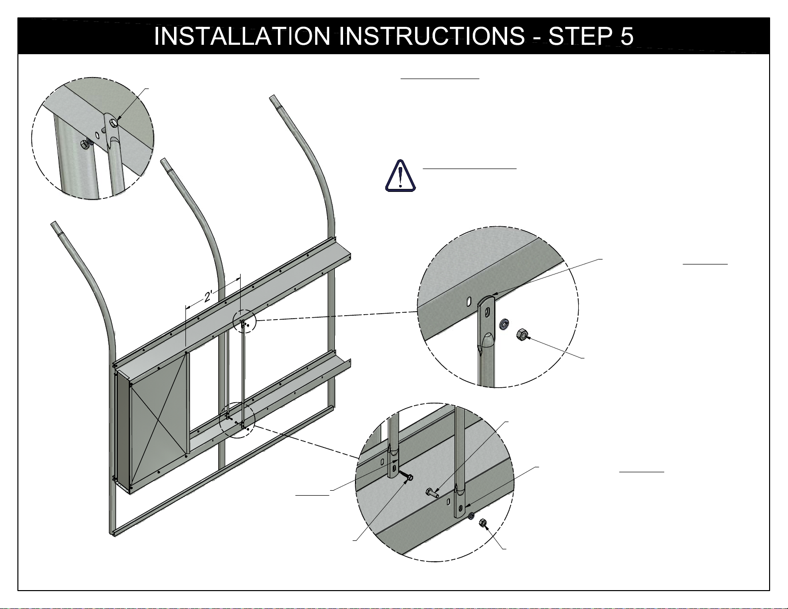
1/4" x 3/4" HEX BOLT,
LOCK WASHER,
& HEX NUT
ATTACHING
THE TOP
OF REAR GUIDE
INSTRUCTIONS:
5A. INSTALL FIRST SET OF GUIDES. THE GUIDES THAT MOUNT TO
THE INSIDE (STRUCTURE SIDE) ARE MOUNTED INSIDE THE
GUTTER FLANGES. THE GUIDES THAT MOUNT TO THE OUTSIDE
OF THE POLY-VENT ARE MOUNTED OUTSIDE THE GUTTER
FLANGES.
IMPORTANT NOTE: ALL BOLTS MUST BE INSTALLED WITH THE
BOLT HEAD ON THE INSIDE OF THE POLY-VENT FRAME TO
PREVENT DAMAGE TO THE POLY-VENT TUBES.
GUIDE MOUNTS OUTSIDE
OF GUTTER FLANGE
1/4" LOCK WASHER
1/4" HEX NUT
1/4" x 3/4" HEX BOLT (INSIDE)
GUIDE MOUNTS INSIDE
GUTTER FLANGE
#12 X 1" SELF
DRILLING SCREW
1/4" x 3/4" HEX BOLT
GUIDE MOUNTS OUTSIDE
OF GUTTER FLANGE
1/4" LOCK WASHER
1/4" HEX NUT
14
Page 15
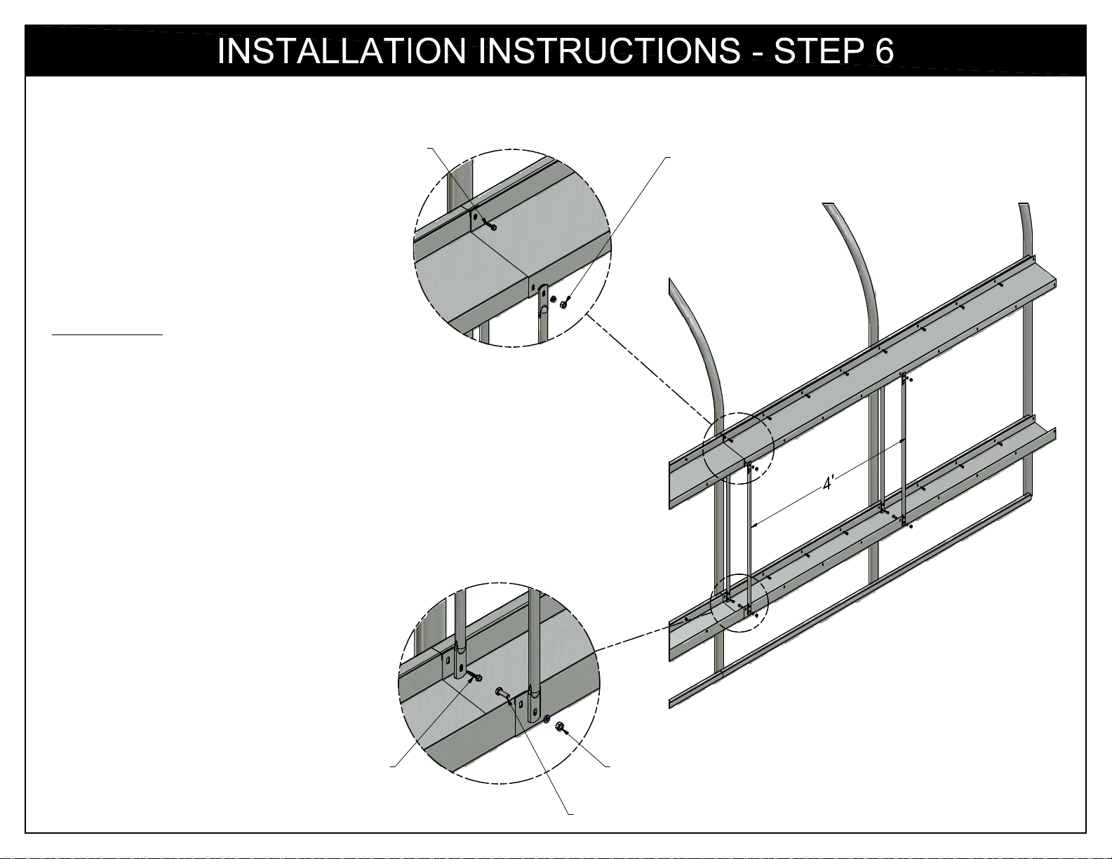
#12 x1" SELF
DRILLING SCREW
INSTRUCTIONS:
6A. INSTALL THE ADJOINING SECTIONS OF TOP
AND BOTTOM GUTTERS.
6B. OVERLAPPING SECTIONS SHOULD BE ASSEMBLED
APPROPRIATELY FOR PROPER WATER DRAINAGE.
ADJOINING GUTTERS SHOULD BE SLID UP INTO
EXISTING GUTTERS IF INSTALLING FROM HIGH END
TO LOW END. ADJOINING GUTTERS SHOULD BE SLID
DOWN OVER THE TOP OF EXISTING GUTTERS WHEN
INSTALLING FROM LOW END TO HIGH END.
6C. CONTINUE TO ADD GUIDES EVERY 4 FEET.
1/4" LOCK WASHER
1/4" HEX NUT
1/4" x 3/4" HEX BOLT (INSIDE)
#12 x1" SELF
DRILLING SCREW
1/4" LOCK WASHER
1/4" HEX NUT
1/4" x 3/4" HEX BOLT
15
Page 16
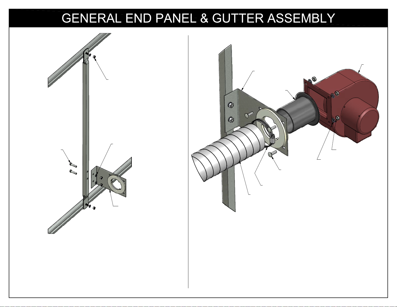
5/16" x 1-1/2"
HEX BOLT
STOP TAB,
5/16" LOCK WASHER,
& HEX NUT
5/16" LOCK WASHER
5/16" HEX NUT
BLOWER
MOUNTING
BRACKET
BLOWER
MOUNTING
BRACKET
PV PLUG
1/4" x 3/4"
CARRIAGE BOLT
3.25" HOSE CLAMP
FLEX TUBING
Insert the pv plug through the blower mount.
BLOWER
1/4" HEX NUT
1/4" LOCK WASHER
Mount the blower mounting rail to your structure's rails.
Use FT2570 Stop Tab, 5/16" Lock Washer and Wing
Nut.
Mount the blower mounting bracket to the blower
mounting rail using the 5/16" fasteners provided.
Bolt the poly-vent blower to the blower mount with the pv plug
between the blower and the mount using (4) 1/4" X 3/4" carriage
bolt, lock washer, and hex nut.
Slide the 3.25" hose clamp over the 3" X 5' flex tube leaving the
clamp loose temporarily.
Slide the 3" X 5' flex tube with the 3.25" clamp over the pv plug
and secure it in place by tightening the 3.25" hose clamp.
16
Page 17
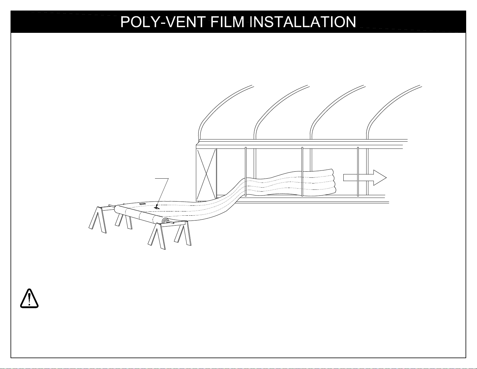
MAKE SURE THE TUBE WITH THE
"THIS SIDE UP" DECAL IS INSTALLED
AT THE TOP
1. Thread the Poly-Vent film through the Poly-Vent frame.
USE CAUTION WITH THIS PROCEDURE. DO NOT LET THE POLY-VENT FILM SNAG ON OR CATCH ANY FRAME PARTS.
2. Center the Poly-Vent within the frame.
3. You can now install the air inlet flex tubing leading from the Poly-Vent blower.
17
Page 18
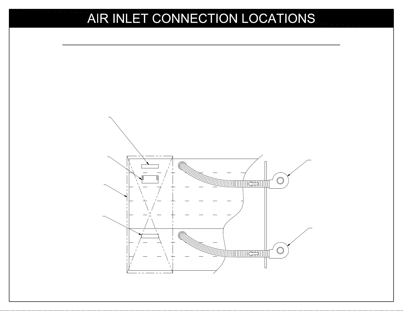
This drawing illustrates where to locate the air inlet(s) on your Poly-Vent.
1. The flex tubing is attached to the very top tube of the Poly-Vent. A decal will show which tube to locate the flex
tubing connection.
2. Poly-Vent III requires two blowers. An additional decal will show which tube to locate the lower flex tubing connection.
"INSTALL FLEX HOSE
IN THIS TUBE" DECAL
"THIS SIDE UP" DECAL
REAR PANEL
"INSTALL FLEX HOSE
IN THIS TUBE" DECAL
INSTALL FLEX HOSE
IN THIS TUBE
POLY-VENT
INSTALL FLEX HOSE
IN THIS TUBE
TOP
POLY-VENT II
BLOWER
POLY-VENT III
BLOWER
(OPTIONAL)
BOTTOM
18
Page 19
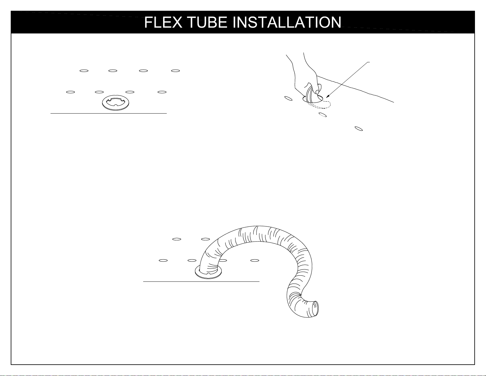
1. Once you have located the correct location
for your flex tube connection, peel off the
backing from one gasket and apply it to the
clean dry plastic.
2. With a sharp utility knife, carefully cut out
the center portion of the plastic, being sure
to cut through the top layer only.
top gasket
not shown
for clarity
3. Remove the paper backing from the second gasket.
Carefully fold in half -- being very careful not to let the
adhesive make contact with itself -- and slip through
the hole just cut.
4. Align the inside gasket with the outside gasket, and
press together. As a safety measure, it is a good idea to
take an office stapler and staple the two gaskets together.
5. Next, insert the flex tube into the opening.
Make sure that there is no sharp wire
exposed that may puncture the Poly-Vent
tube.
19
Page 20
NOTE: THIS BASIC POLY-VENT OPERATION PAGE IS FOR PVII (SINGLE-STAGE) SYSTEMS ONLY.
IF YOU PURCHASED A PVIII (TWO-STAGE) SYSTEM, SEE THE FOLLOWING PAGE FOR THE
CORRECT BASIC POLY-VENT OPERATION.
Thermostats for the Poly-Vent system should be mounted approximately centered between each sidewall and centered from
front to rear of the structure. They should be mounted at eye level. However, some growers prefer to mount thermostats at
bench height.
Initial start-up: PVII Two Stage Poly-Vent
When inflating the Poly-Vent for the first time - before wiring the thermostat - turn on the blower. Moving from one end to the
other, manually help the Poly-Vent tubes up so that they do not twist.
The included wiring diagrams should be used to wire the thermostat into the system. Note that the wiring circuits more resemble
a "heating" circuit than a "cooling" circuit. This is the correct way to wire your thermostat. Please wire exactly as shown for
correct results.
With the Poly-Vent deflated, slowly turn the thermostat to a higher temperature until the blower is activated. If the system is
operating properly, the blower will activate and inflate the PVII system.
After the Poly-Vent has been successfully inflated, check for proper complete inflate/deflate cycle operation.
Now adjust the thermostat to the desired temperature to be maintained in your structure.
NOTE: If you have a BUBS (Back-Up Blower System) the BUBS is not generally wired to the thermostat so that if it is activated,
the Poly-Vent will remain inflated and will not cycle again until the power is restored.
20
Page 21
NOTE: THIS BASIC POLY-VENT OPERATION PAGE IS FOR PVIII (TWO-STAGE) SYSTEMS ONLY.
IF YOU PURCHASED A PVII (SINGLE-STAGE) SYSTEM, SEE THE PREVIOUS PAGE FOR THE
CORRECT BASIC POLY-VENT OPERATION.
Thermostats for the Poly-Vent system should be mounted approximately centered between each sidewall and centered from
front to rear of the structure. They should be mounted eye level. However, some growers prefer to mount thermostats at bench
height.
Initial start-up: PVIII Two Stage Poly-Vent
When inflating the Poly-Vent for the first time - before wiring the thermostat - turn on the top blower only. Moving from one end to
the other, manually help the Poly-Vent tubes up so that they do not twist. After the top section is completely inflated, turn on the
lower blower (before wiring to the thermostat). Again, moving from one end to the other, manually help the lower Poly-Vent tubes
up so that they inflate properly.
The included wiring diagrams should be used to wire the thermostats into the system. Note that the wiring circuits more resemble
a "heating" circuit than a "cooling" circuit. This is the correct way to wire your thermostats. Please wire exactly as shown for
correct results.
With the Poly-Vent deflated, slowly turn the thermostat to a higher temperature until one of the blowers is activated. If the system
is operating properly, the top blower will activate first and inflate the upper section of the PVIII system. Once the upper section of
the PVIII is inflated, slowly continue to raise the temperature of the thermostat in approximately 3 to 6 degree increments until
the lower blower motor activates inflating the lower section of the PVIII.
After the Poly-Vent has been successfully inflated, check for proper complete inflate/deflate cycle operation. Slowly lower the
temperature adjustment until the lower blower shuts off. If the lower blower motor is shut off first, the system is operating
properly.
Now adjust the thermostat to the desired temperature to be maintained in your structure.
NOTE: If you have a BUBS (Back-Up Blower System) the BUBS is not generally wired to the thermostat so that if it is activated,
the Poly-Vent will remain inflated and will not cycle again until the power is restored.
21
Page 22
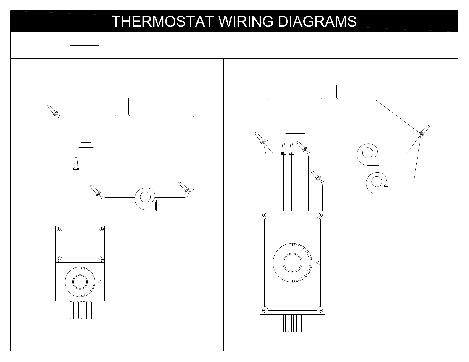
NOTE: BOTH THESE CIRCUITS MORE RESEMBLE A "HEATING" CIRCUIT
THAN A "COOLING" CIRCUIT. PLEASE WIRE EXACTLY AS SHOWN.
POWER SOURCE
POWER SOURCE
(110V)
L1
L2
(110V)
L1
L2
WHITE
BLACK
GREEN
BLACK
BLUE NOT USED
BLACK
RED
WHITE
WHITE
GREEN
BLACK
BOTTOM
BLOWER BLACK
PINK
BROWN
BLACK
BLUE NOT USED
VIOLET NOT USED
TOP BLOWER
BLACK
RED
BOTTOM
BLOWER
WHITE
TOP
BLOWER
WHITE
SINGLE STAGE
(Poly-Vent II)
TWO STAGE
(Poly-Vent III)
22
Page 23
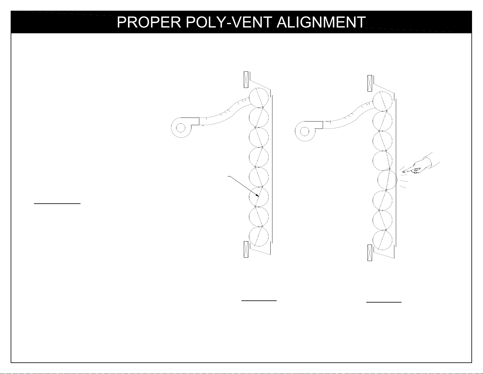
IMPORTANT:
This drawing illustrates end views of the
Poly-Vent. When inflated, the Poly-Vent tubing
seals will form a "zig-zag" profile. If you have
one tube that is bulging, check your zig-zag
pattern by inserting your hand in between the
poly tubes. You will notice one row of seals are
towards the inside, one row towards the outside,
then inside, etc. (see Figure A).
correct
"zig-zag"
profile
To fix the bulge, simply force the bulge inward
with your hand the full length of the vent (Figure
B).
Figure A
Figure B
23
Page 24
Blower fan does not rotate No power to motor Check power source (most often the cicuit panel).
Obstruction in blower Turn off power source and check blower for debris.
Damaged blower Replace the blower.
Thermostat set too high Adjust the thermostat to a lower temperature.
Blower "hums" but fan does Incorrect voltage Check power source for correct voltage.
not rotate
Obstruction in blower Turn off power source and check blower for debris.
Blower fan rotates but Faulty flex tube Check flex tube for damage or obstructions.
Poly-Vent does not inflate
Poor flex tube connection(s) Check connection around air transfer gaskets for leaks.
Poly-Vent does not inflate Air leaking somewhere in the Check for holes or tears in Poly-Vent and repair with
completely Poly-Vent Poly Patch tape.
Water accumulation in Poly-Vent If water should accumulate, it might accumulate in just
one of the tubes. Make a 1/2" to 1" slit where the water
has accumulated and drain the water. Repair the slit
with Poly Patch tape.
Poly-Vent III only: Thermostat not wired correctly Remove pink wire from the thermostat to the top
Top blower shuts off before to blower motor blower motor and attach to the lower blower motor.
the bottom blower Remove the red wire from the lower blower motor and
attach to the top blower motor.
Q. How much time does it take to inflate and/or deflate the Poly-Vent?
A. The length of time necesary to inflate or deflate the Poly-Vent is variable depending on several factors. Length of
F.A.Q.
Poly-Vent, height of Poly-Vent, and the number and location of the blowers connected to the Poly-Vent. Obviously,
the longer the Poly-Vent, the more time is necessary to inflate and deflate. The same applies to different Poly-Vent
heights. A Poly-Vent II (single stage) system will take more time to inflate or deflate than a Poly-Vent III (two-stage)
system due to the fact that all the air must pass through more tubes and enter and exit through just one blower.
24
Page 25
Below are some hints on how to properly care
for your new Poly-Vent system.
1. Inflate the Poly-Vent occasionally - even during hot weather - to keep it in proper working
order.
2. Do not set objects on the Poly-Vent when it is deflated.
3. Inflate your Poly-Vent after a rain to let any accumulated water drain off.
4. Check periodically for tears or punctures. If any holes are found, repair with Polypatch tape.
5. Keep the gutters free of dirt and debris for a tight seal.
6. When Poly-Vent is not used for long periods, or is simply becoming dirty, inflate the vent
and rinse off the inside and outside of the tubes with water.
7. If you are in a climate where you won't need your Poly-Vent for long periods of time, remove
it from the structure and store it in a safe place out of the weather.
8. Regularly check the blowers and flex tube(s) for damage or obstructions.
25
Page 26
Limited Warranty
Poly-Tex, Inc. warrants its products to be free from defects in material and workmanship for a
period of (1) year from date of invoice. This warranty is provided to the original purchaser of the
product and is not transferable. Poly-Tex does not warrant parts not manufactured by Poly-Tex,
but does assign any transferable manufacturer or supplier warranties. Should any defect be
found, full repair or replacement will be rendered to the customer at no cost following inspection
by a Poly-Tex representative and the return of the defective product to our Castle Rock, MN
factory. Expenses for removal or reinstallation of defective products will not be covered by the
warranty.
POLY-TEX SHALL NOT BE HELD RESPONSIBLE FOR ANY SPECIAL OR
CONSEQUENTIAL DAMAGES, OR FOR ANY DELAY IN PERFORMANCE OF THIS
WARRANTY BEYOND OUR CONTROL. THIS WARRANTY IS EXCLUSIVE AND IN LIEU OF
ALL OTHER WARRANTIES WHETHER IMPLIED, WRITTEN OR ORAL INCLUDING THE
WARRANTIES OF MERCHANTABILITY AND FITNESS FOR A PARTICULAR PURPOSE.
This warranty does not cover damage from customer abuse, misuse, improper installation,
customer modifications, customer negligence in performing normal maintenance, damage
resulting from acts of nature.
Extended Warranty for Poly-Vent film
Poly-Vent film is warranted for up to three years from invoice date against defects in material and
workmanship as well as deterioration due to ultraviolet rays. Should Poly-Vent film fail due to
workmanship or UV deterioration, Poly-Tex will replace your Poly-Vent film using the following
graduated scale:
Up to 12 months.................100% of cost of materials
13 to 24 months....................50% of cost of materials
25 to 36 months...................20% of cost of materials
37 to 48 months.....................5% of cost of materials
26
 Loading...