

Page 1
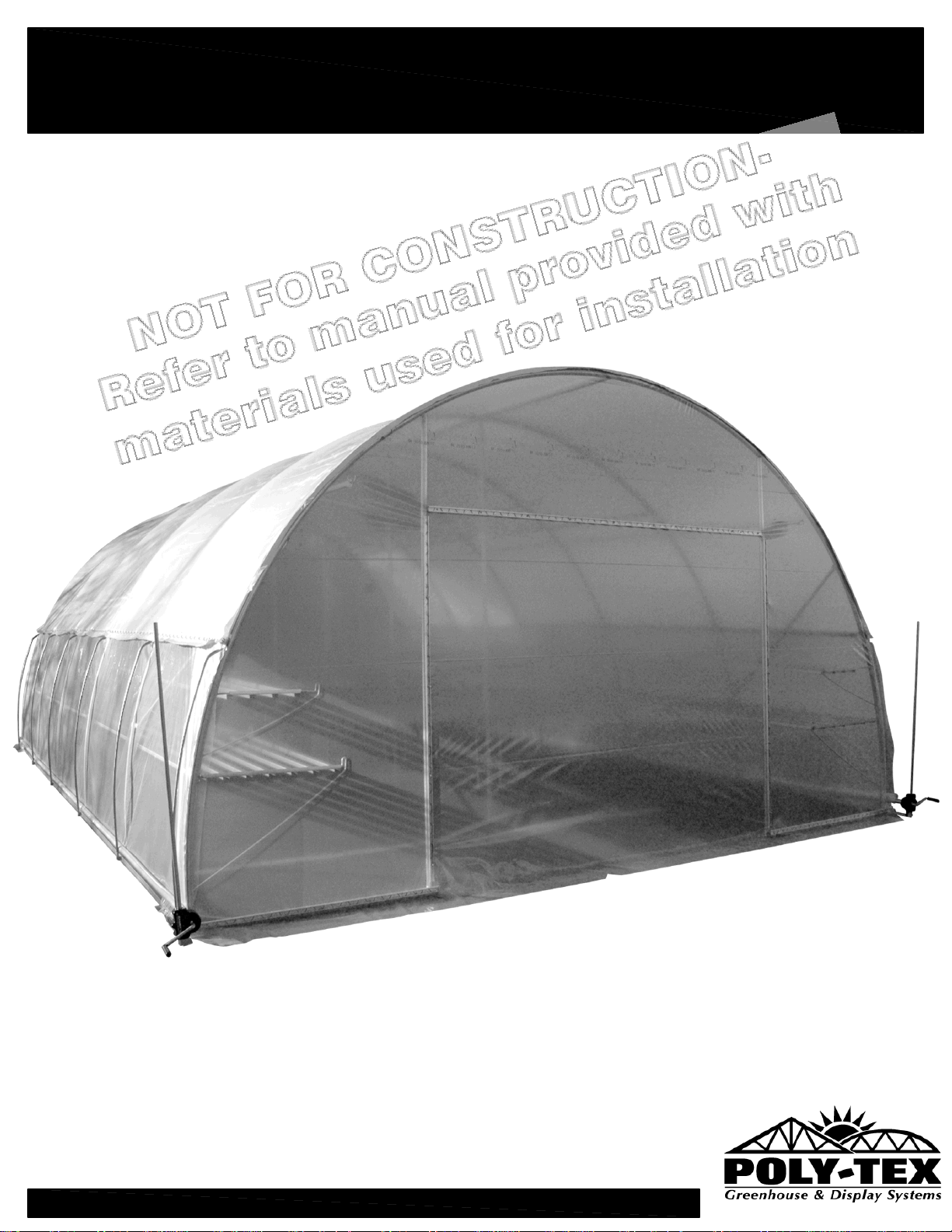
KOOL MART with roll-up sides
INSTALLATION INSTRUCTIONS
Poly-Tex Inc.
27725 Danville Avenue
P.O. Box 458
Castle Rock, MN 55101
REV: AD-130315
US & Canada Toll Free
800-852-3443
(651) 463-7009
fax (651) 463-2479
Page 2
SAFETY GUIDELINES
PLEASE READ THE INSTALLATION INSTRUCTIONS CAREFULLY BEFORE
ASSEMBLING THE STRUCTURE. SAVE THESE INSTRUCTIONS FOR FUTURE REFERENCE.
WARNING
This structure is intended to be self-supporting once constructed with all frames,
hardware, sheathing, sheeting, bracing, cables, and membrane in place and secured to the
foundation as shown in the manual. Stability during construction, from winds and loads
imposed during erection, is the sole responsibility of the installer. Observe safety codes
required by your jurisdiction, and relevant safety practices for working at heights. Avoid the
risk of electrical shock from overhead lines or electrical storms. Poly-Tex recommends
contracting a licensed electrician to perform electrical work. Eye protection is recommended
under all circumstances and hearing protection is recommended when cutting components
with power tools.
Foundations
These instructions include minimum guidance for foundations based on the International
Building Code. These minimums are suitable for some areas of the country but not all.
Obtain a building permit if required in your jurisdiction. Engineered Certified foundation plans
may be required by a building official before issuing a permit. Even if not required, seeking
guidance from a qualified structural or civil engineer for the foundation design may improve
the life of the structure.
DANGER
No part of this structure is engineered to function as an anchorage point for a fall arrest
system. Use a safety net or work from a safe work platform (i.e. scaffolding). Select a calm
day for work. Wind can be sufficient enough to knock materials or workers off a work platform
or ladder, resulting in a potentially deadly fall.
Overview of assembly procedure
While each structure and site is unique, and may require special considerations, these
instructions are for a tilt-up method (where frames are assembled on the ground and tilted
onto ground stakes or anchor rods using ropes or lifts). If installer is not confident to erect the
structure, Poly-Tex suggests you hire a general contractor, carpenter, or similar licensed
business familiar with construction to assemble and erect the structure.
DANGER
Do not overload structure. Consult with a Poly-Tex representative prior to adding any
amount of weight over the specified capacity of this structure. Basket purlins, shelving or any
objects of significant weight shall not be hung, attached, or secured to roof or truss members
in a manner that will overload the structure.
WARNING
Do not walk on polycarbonate sheets. If the structure is to be covered with polycarbonate
sheets,always use scaffolding for the erection process to avoid damage to sheeting and to
ensure safety. Polycarbonate sheeting has UV coating protected with vinyl film on the
exterior surface. Install sheets with the film intact and toward the exterior. Remove film once
the sheet has been fastened in place.
REV: AD-130315
Page 3

KOOL MART
With Roll-up sides
INDEX
Part Identification....................................................................................1
Part Identification...............................................................................2
Layout & Base Assembly...................................................................3
Frame Section Assembly......................................................................4
Stand up Frame Sections....................................................................5
Door Installation..................................................................................6
“V” Bracket & Basket Purlin.................................................................7
Basket Purlin &“V” Bracket &Ballast Frame..........................................8
Concrete Block Installation.............................................................9
Water Tube Installation.................................................................10
Retro Roll-Up Side Application.............................................................11
Wiggle Base Rails & End Poly Installation....................................12
Roll-up Curtain Attachment................................................................13
Guide & Roll-up Assembly..................................................................14
Poly Installation....................................................................................15
REV AD-130315
Page 4
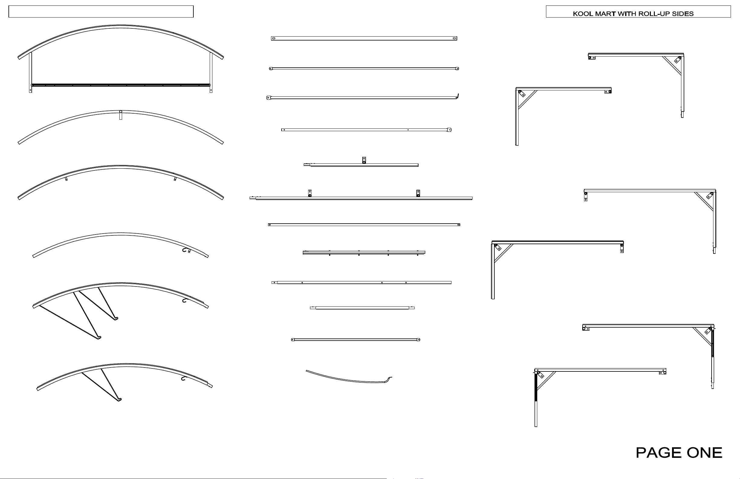
KM2001 - TOP END HOOP
PART IDENTIFICATION
KM2035 - LEFT CORNER BASE (ROLL-UP)
KM2008 - 6' DOOR SPACER
KM2000 - TOP INTERMEDIATE HOOP
KM2005 - TOP END HOOP W/TABS
KM2021 - ROLL UP DOOR PIPE (126")
KM2010 - SLIDING DOOR END BRACE (95 1/2")
KM2009 - SLIDING DOOR VERTICAL
KM2032 - 6' SIDE BASE
KM2033 - 12' SIDE BASE
KHR1018 - DOOR SPACER
KM2034 - RIGHT CORNER BASE (ROLL-UP)
KM2029 - LFT CRN BASE (SLIDING DR, ROLL-UP)
KM2038 - RT CRN BASE (SLIDING DR, ROLL-UP)
KM2030 - INTERMEDIATE HOOP
KM2031 - END HOOP W/WWB
KM2016 - END HOOP W/WWR (BALLAST)
KHR1036 - DOOR JAMB
KHR1040 - POWER POLE
KHR1044 - RIDGE PURLIN
KHR1046 - DIAGONAL BRACE (85 1/2")
KM2040 - ROLL-UP CURTAIN GUIDE (KM)
KM2037 - LFT CRN BASE (NO DOOR, ROLL-UP)
KM2036 - RT CRN BASE (NO DOOR,ROLL-UP)
REV: AD-130315
Page 5
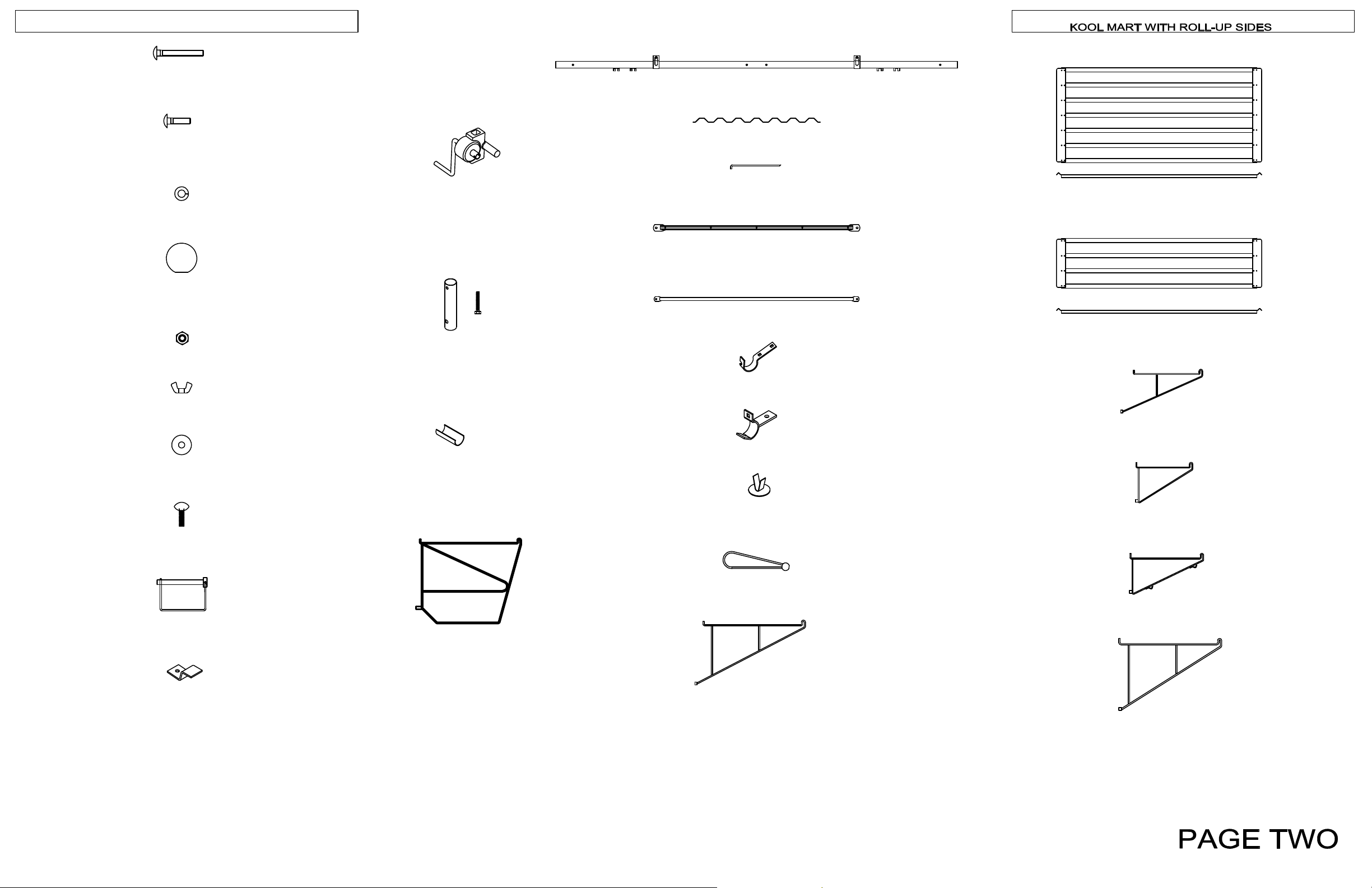
NB1816 - 5/16" x 2 1/2" CARRIAGE BOLT
PART IDENTIFICATION
GM2802 - ROLLING DOOR RAIL
NB1832 - 5/16" x 1 1/4" CARRIAGE GRD 5
NB1862 - 5/16" LOCK WASHER
NB1927 - CUSHION BALL
NB1872 - 5/16" HEX NUT
NB1901 - 3/8" WING NUT
NB1923 - NYLON WASHER
MANUAL ROLL UP UNIT NS101
GEARBOX EXTENSION W/BOLT
ROLL-UP TUBE CLIP 1.315"
MV1000
RC1009
RC1010
WIGGLE WIRE ™
BMS1130 - 18" SPIKE
GM2803 - ROLLING DOOR HEADER
GM4000 - 6'-1-1/2" BASKET PURLIN -95
FT2080 - 1.66 HOOK
FT2087 - 1.66 INLINE SPEED HOOK
RF2552 - 3' x 6' BENCH TOP
RF2554 - 1'6" x 6' BENCH TOP
KM2003 - 24" KM BENCH BRACKET
NB1924 - 5/16" x 1" THUMB SCREW
NB1925 - SNAPPER PIN
FT3200 - FLAT STACKER CLIP
KM2015 - 36" KM BENCH FRAME
GM2970 - HOOP PAD
PT2521 - 10" BUNGEE BALL
KM2004 - 36" KM BENCH BRACKET
BMS1120 - 18" V BRACKET
KHR1048 - HANGING BASKET "V" BRACKET
BMS1121 - 36" V BRACKET
REV: AD-130315
Page 6
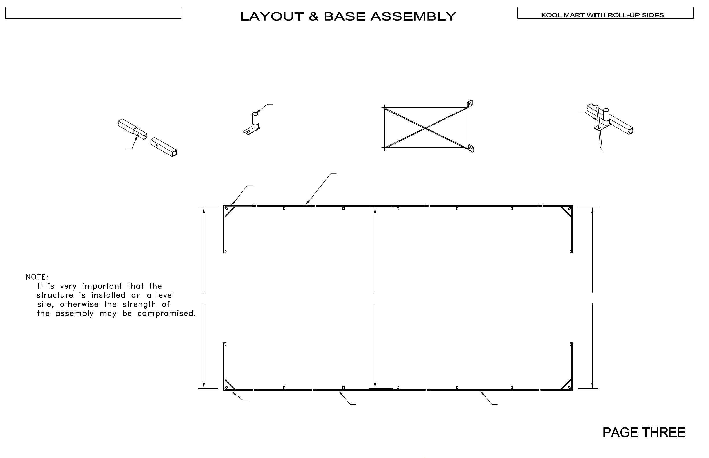
BASE ASSEMBLY
SQUARE THE BASE
FINAL BASE ASSEMBLY
To assemble the base, connect corner bases, six foot
side bases, and twelve foot side bases to length of
greenhouse. These are secured together with snap
buttons incorporated with the part.
Note: Not all KOOL MART's will contain a 6' base.
SNAP BUTTON
When measuring the width of the greenhouse, measure
from center-to-center of 5" inserts. The width should be
20'. Also measure diagonally across the base from
corner-to-corner to make sure that the base is square.
CENTER OF 5" INSERT
KHR1012
LEFT CORNER
KHR1014
6' SIDE BASE (OPTIONAL)
BASE
After you have assembled and squared the entire base
of the KOOL MART, drive one 18" spike through the
hole in each plate that accompanies the 5" insert.
18" SPIKE
BMS1130
REV: AD-130315
20'-0"
KHR1010
RIGHT
CORNER
BASE
20'-0"
KHR1016
12' SIDE BASE
20'-0"
KHR1016
Page 7
KOOL MART WITH ROLL-UP SIDES
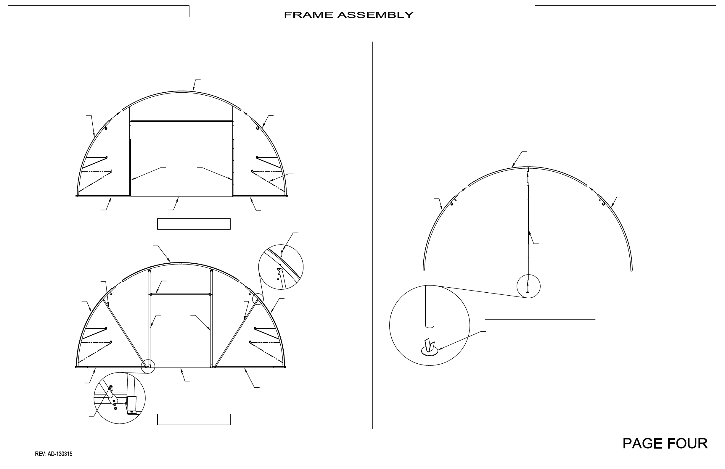
Lay parts out on a flat surface, and assemble the
End Frame Sections as shown (Door Sections shown).
Make sure all snap buttons are secured.
NOTE: Determine type of Door and assemble accordingly.
KM2001
Lay parts out on a flat surface and assemble the
Intermediate Frame Sections as shown.
Make sure all snap buttons are secured.
KHR1020
KHR1021 (BALLAST)
KHR1012
KM2010
KHR1018
KM2005
KHR1036
ROLL-UP DOOR END
GM2803
KHR1020
KHR1021 (BALLAST)
(INDICATES KM2016)
KHR1010
5/16" X 2 1/2"
CARRIAGE BOLT
LOCK WASHER &
HEX NUT
KM2002
KM2000
KM2002
KHR1040
KHR1020
KHR1021 (BALLAST)
KM2007
5/16" X 2 1/2"
CARRIAGE BOLT
LOCK WASHER
& HEX NUT
KM2010
KM2009
KM2008
SLIDING DOOR END
KHR1020
KHR1021 (BALLAST)
INTERMEDIATE FRAME SECTION
GM2970
KM2006
Page 8
STAND UP FRAME SECTIONS
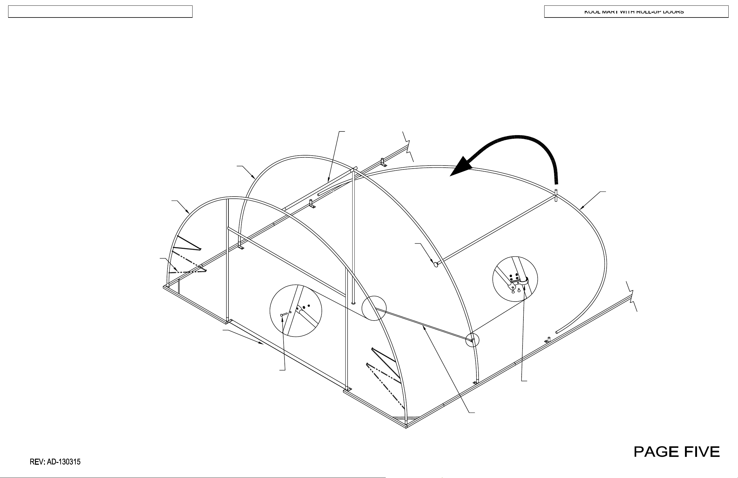
First, stand up one end frame section on the end 5" inserts.
Next, stand up an intermediate frame section on the next 5" inserts.
Then, insert a ridge purlin (KHR1044) between the peaks
of the frame sections.
Ensure all snap buttons are secured.
Attach diagonal braces (KHR1046) to each corner with long speed
hooks (FT2080), 5/16" x 1 1/4" carriage bolts, and 5/16" X 2 1/2"
carriage bolts. Tighten snugly.
Continue down the rest of the Kool Mart with intermediate frame
sections and ridge purlins. Finish with the frame section on the
other end.
INTERMEDIATE FRAME SECTION
END
FRAME SECTION
RIDGE PURLIN
(KHR1044)
INTERMEDIATE
FRAME SECTION
(INDICATES KHR1020-
NO BALLAST)
DOOR SPACER
(KHR1014)
2 1/2" CARRIAGE BOLT
LOCK WASHER & HEX NUT
HOOP PAD
(GM2970)
(2)1.66" HOOKS (FT2080)
W/ 5/16" X 1 1/4" CARRIAGE BOLT
LOCK WASHER & HEX NUT
DIAGONAL BRACE
(KHR 1046)
Page 9
KOOL MART WITH ROLL-UP SIDES
WIGGLE WIRE
BUNGEE BALL
VINYL DOOR
CUSHION
BALL
VINYL DOOR
GROMMET
3/8" WING NUT,
NYLON WASHER
SNAPPER PIN
NB1925
VINYL DOOR
CLOSED VIEW
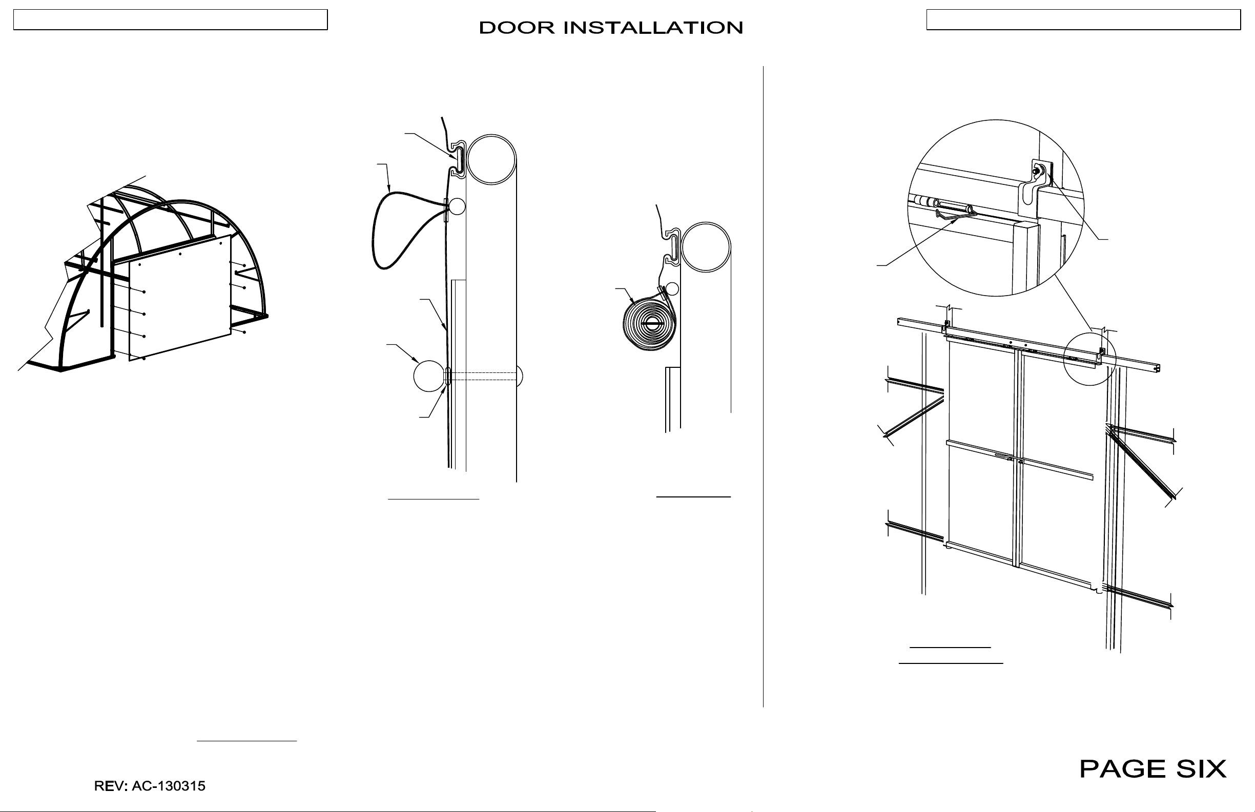
1. Secure door to jambs using (6) cushion balls (NB1927) and
carriage bolts.
2. Fasten top of door to header using wiggle wire.
To open door, remove cushion balls and place them where they can be
found easily. Roll up door and secure inside bungee balls.
To close door, place grommets over bolt ends on the front of the door
jambs and secure with cushion balls.
ROLL-UP DOOR
OPEN VIEW
INSIDE VIEW
SLIDING DOORS
Refer to instructions included with the door latch kit to
assemble latches to the doors.
Page 10
KOOL MART WITH ROLL-UP SIDES
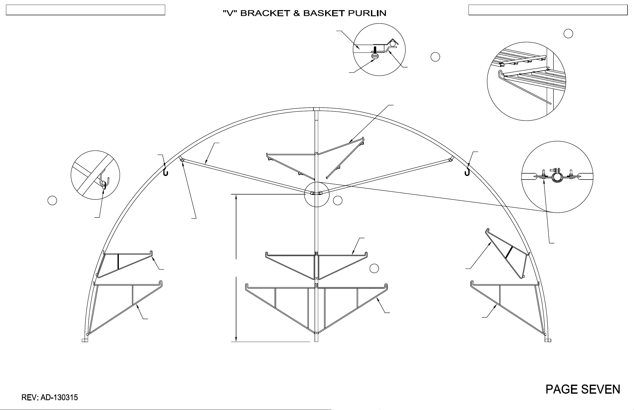
1. Install the "V" brackets onto the center poles and intermediate
frame sections by inserting them into the pre-drilled holes.
2. Attach Inline fitting to power pole at appoximately 84". Attach
purlin to inline fitting and hoop tabs and adjust if necessary.
3. Install the basket purlin by hooking it on the basket purlin hooks.
4. Place bench tops on "V" brackets as shown.
BENCH TOP
THUMB SCREW
5
FLAT STACKER CLIP
PLACING BENCH TOPS
4
5. Use flat stacker clips to secure bench tops to "V" brackets on
each end of the four center benches using thumb screws.
BASKET
PURLIN
HOOK
3
5/16" X 1 1/4"
BASKET PURLIN
GM4000
CARRIAGE BOLT,
LOCK WASHER,
& HEX NUT
KM2003
APPROXIMATELY
V-BRACKET
GM4000 PURLIN
84"
KHR1048 V-BRACKET
W/BASKET PURLIN HOOKS
BASKET
PURLIN
HOOK
2
INLINE FITTING
BMS1120
V-BRACKET
5/16" X 1 1/4"
CARRIAGE BOLT,
LOCK WASHER
& HEX NUT
1
KM2003
V-BRACKET
KM2004
V-BRACKET
BMS1121
V BRACKET
KM2004
V-BRACKET
Page 11
KOOL MART WITH ROLL-UP SIDES
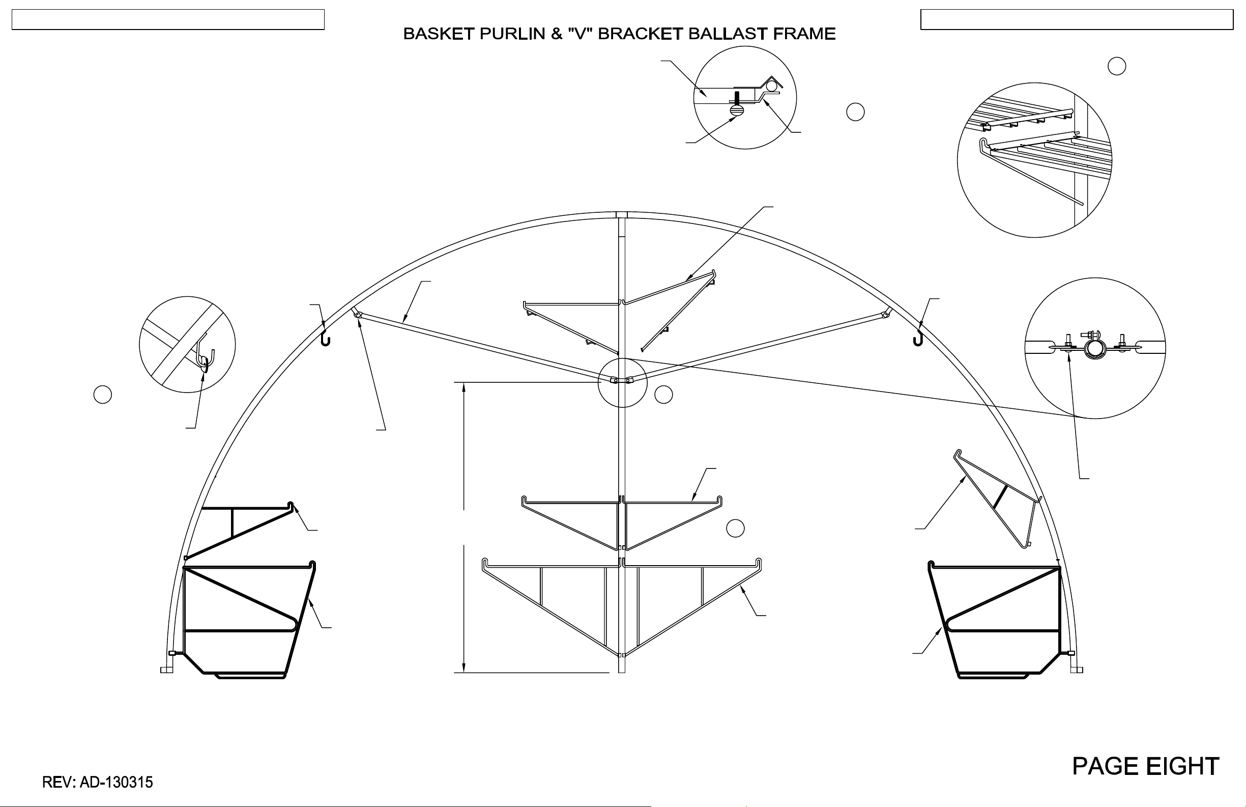
1. Install the "V" brackets onto the center poles and intermediate
frame sections by inserting them into the pre-drilled holes.
2. Attach Inline fitting to power pole at appoximately 84". Attach
purlin to inline fitting and hoop tabs and adjust if necessary.
3. Install the basket purlin by hooking it on the basket purlin hooks.
4. Place bench tops on "V" brackets as shown.
BENCH TOP
THUMB SCREW
5
FLAT STACKER CLIP
PLACING BENCH TOPS
4
5. Use flat stacker clips to secure bench tops to "V" brackets on
each end of the four center benches using thumb screws.
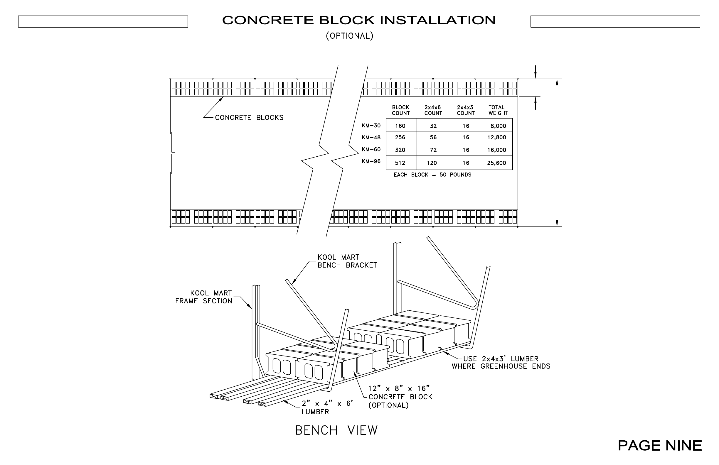
See Page 9 for preferred ballast installation, and page 10 for
alternate Water tube installation.
BASKET
PURLIN
HOOK
5/16" X 1 1/4"
BASKET PURLIN
GM4000
CARRIAGE BOLT,
LOCK WASHER,
& HEX NUT
KM2003
APPROXIMATELY
V-BRACKET
GM4000 PURLIN
84"
KHR1048 V-BRACKET
W/BASKET PURLIN HOOKS
BASKET
PURLIN
HOOK
23
INLINE FITTING
BMS1120
V-BRACKET
5/16" X 1 1/4"
CARRIAGE BOLT,
LOCK WASHER
& HEX NUT
1
KM2003
V-BRACKET
KM2015
KM BENCH FRAME
BMS1121
V BRACKET
KM2015
KM BENCH FRAME
Page 12
30"
KOOL MART WITH ROLL-UP SIDES
21'-0"
REV: AD-130315
Page 13
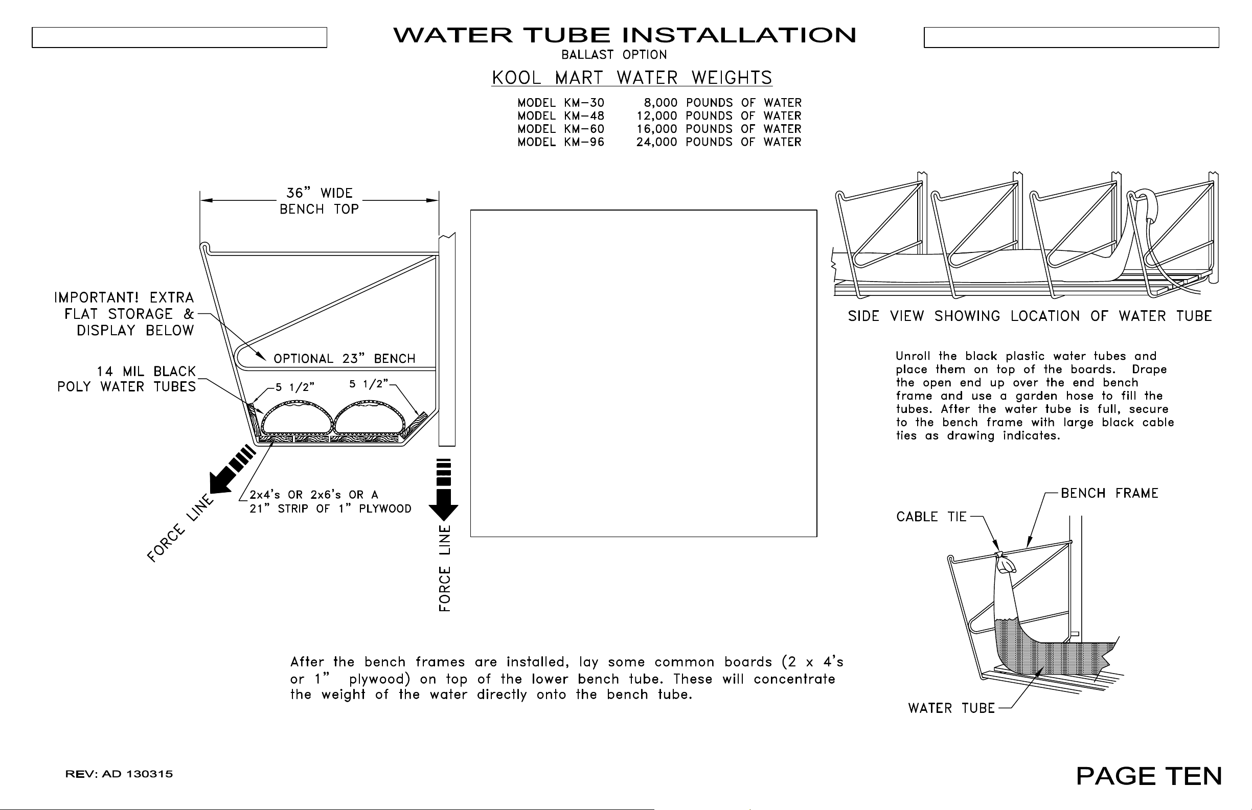
IMPORTANT NOTE:
LUMBER SUCH AS 2 x 4's, 2 x 6's
OR 1" THICK PLYWOOD MUST BE USED
TO HELP CONCENTRATE WATER
KOOL MART WITH ROLL-UP SIDES
TUBE WEIGHT OVER THE BENCH
FRAMES.
DIVERTING FROM THIS
PROCEDURE CAN CAUSE
SERIOUS DAMAGE TO YOUR
STRUCTURE UNDER WINDY
CONDITIONS.
Page 14
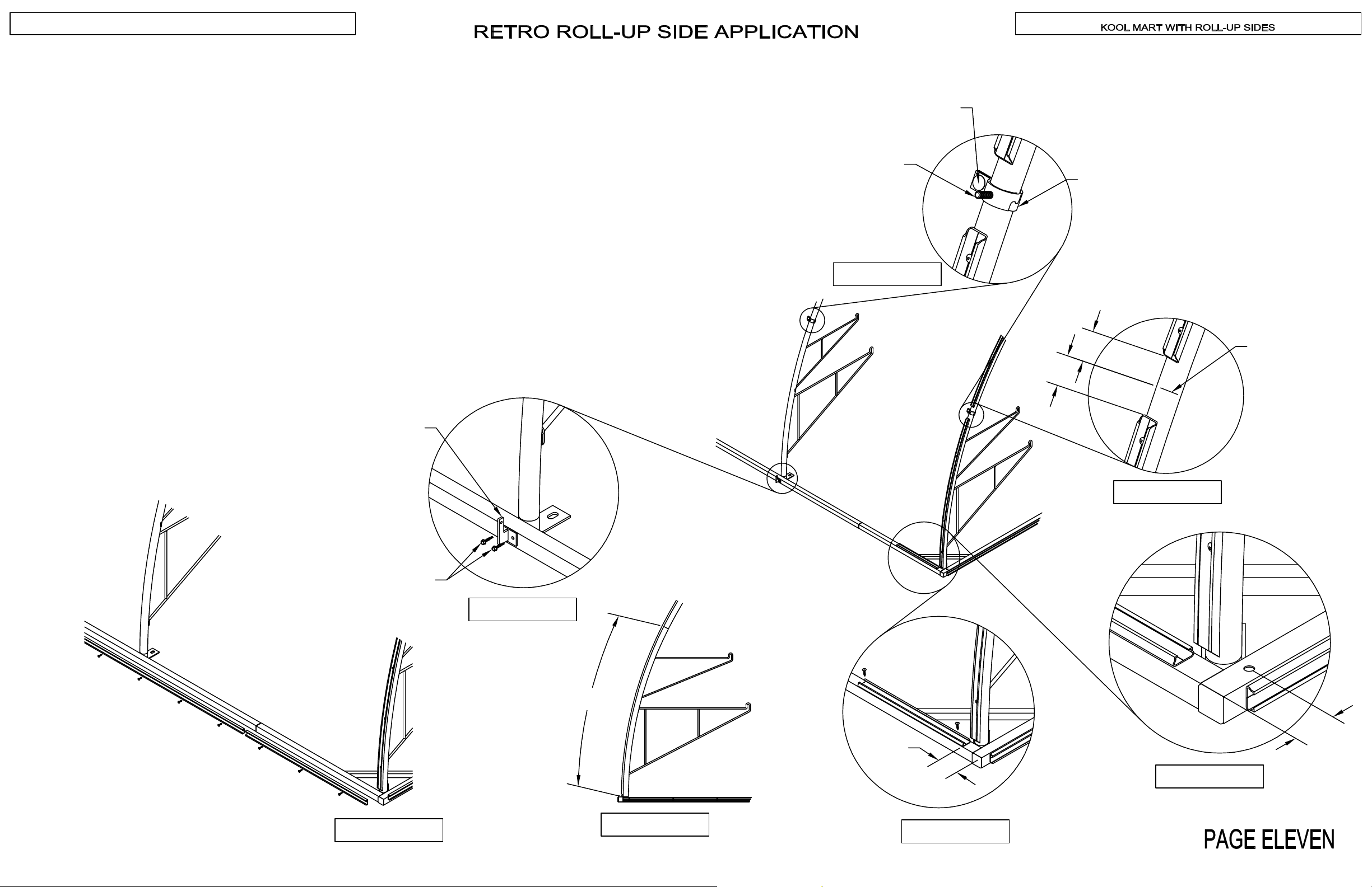
NOTE: IF THIS IS A NEW CONSTRUCTION, SKIP TO PAGE SEVEN
1. After poly has been removed from the roof, remove screws and wiggle wire base from both sides of
structure (FIGURE 1).
2. Place a mark at 55 1/4" from bottom of frame on each hoop (FIGURE 2).
3. Attach 18" wiggle wire base 3 1/4" from end to each corner using 2 #12-14 X 1" self-drilling screws
(FIGURE 3).
4. Cut out 4" of wiggle wire base at each corner frame section at the mark placed in step 2 (FIGURE 4).
5. Attach stud hook and short speed hook at the mark measured in step 2 with the bolt and tab facing
towards the inside of the greenhouse (FIGURE 5).
6. Attach the Roll-up Guide Bracket at each hoop using 2 #12-14 X 1" self-drilling screws (FIGURE 6).
7. Drill 1/2" hole 2" from end at each corner on one end to secure gearbox guides (FIGURE 7).
5/16" x 1 1/4" CARRIAGE
BOLT, LOCK WASHER,
& HEX NUT
STUD HOOK
FIGURE 5
SHORT SPEED
HOOK
2"
2"
MARK
ROLL-UP GUIDE
BRACKET
#12-14 X 1" SELF
DRILLING SCREW
FIGURE 4
FIGURE 6
55 1/4"
2"
REV: AD-130315
FIGURE 1
FIGURE 2
3 1/4"
FIGURE 7
FIGURE 3
Page 15
KOOL MART WITH ROLL-UP SIDES
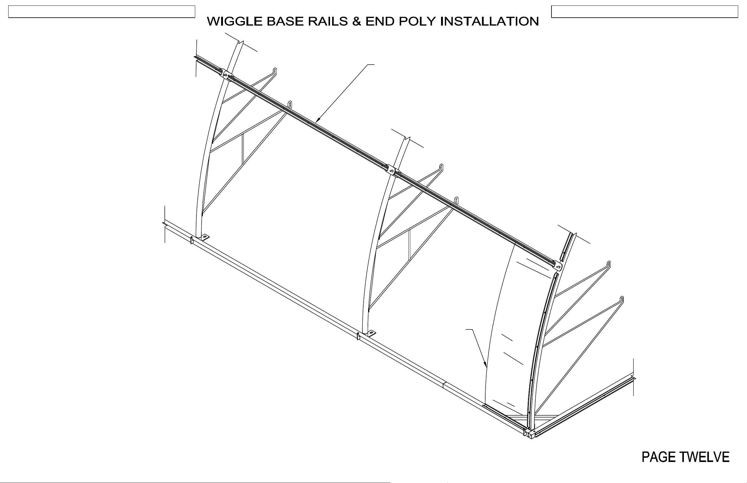
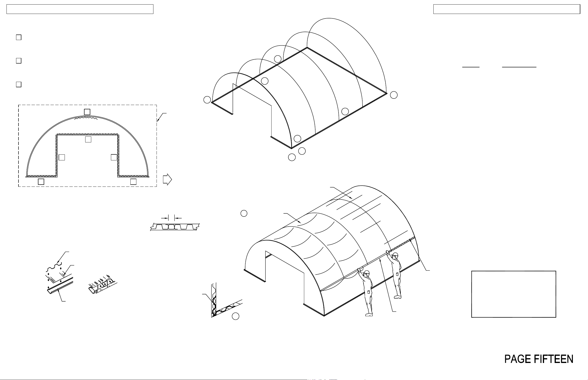
SM4012
After installation of the frame sections, place SM4012 rails on the studs. Rails will be secured later.
Fasten end panel RC1308 to poly fastener base using wiggle wire on three sides as shown.
For ease of access, lay out nominal 5 foot wiggle wire pieces in handy locations along the side of the structure.
REV: AD-130315
RC1308
Page 16
KOOL MART WITH ROLL-UP SIDES
GEARBOX END
2"
POLY CURTAIN
59-1/2"
WIGGLE WIRE
LENGTH AS
REQUIRED
DO NOT OVERLAP
STUDS WITH WIGGLE WIRE
59-1/2"
WIGGLE WIRE
FIGURE 1
66"
2"
POLY CURTAIN
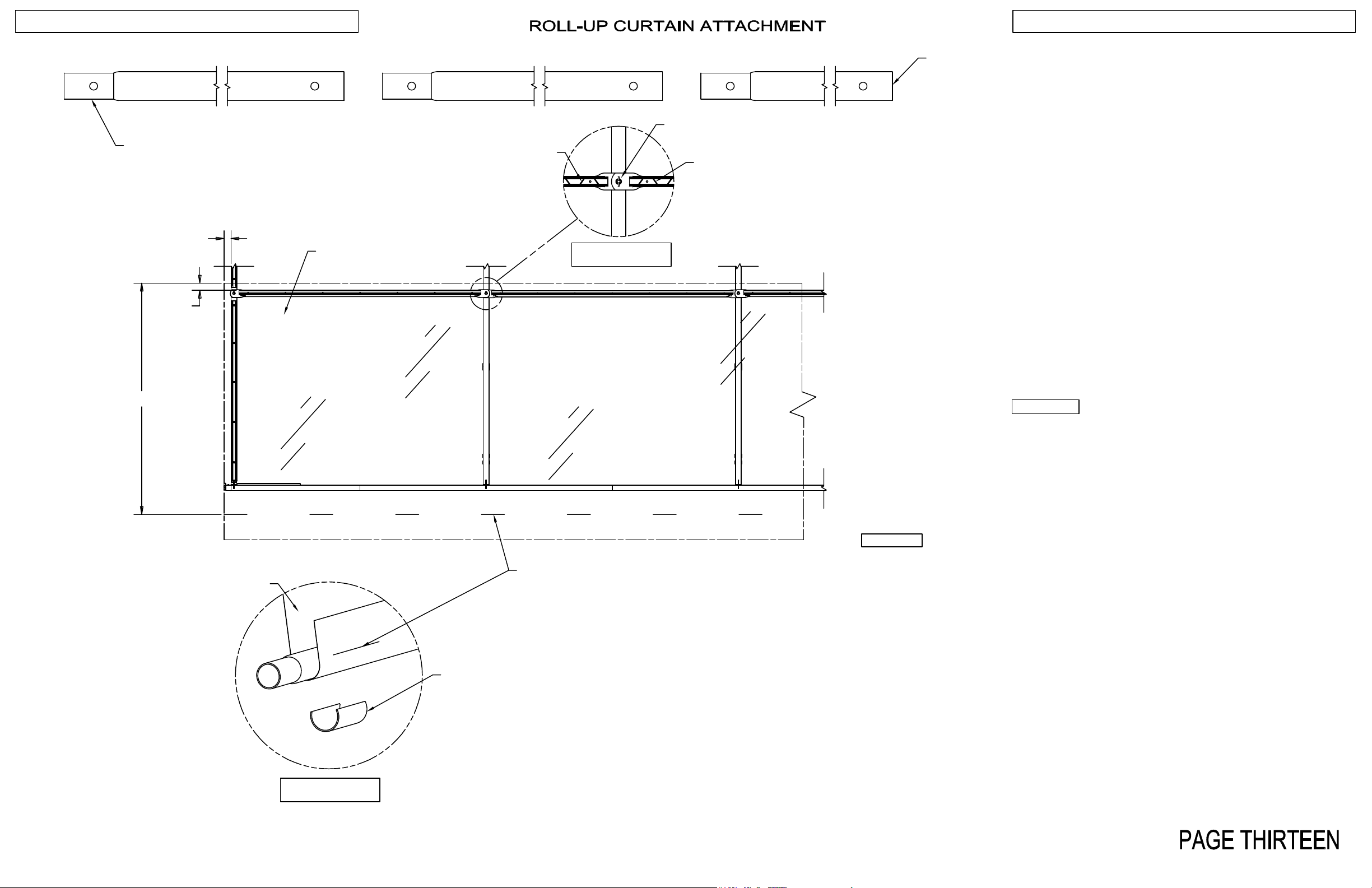
Unroll and position the “roll-up curtain” poly film along each side of the
structure. Be sure to have equal excess film on both ends. For best
results, work from the middle of the structure and move to the ends when
securing the poly. Using the edge of the poly as a guide, raise the poly
into place with about 2” above the rail and secure the poly to the poly
fastener base using wiggle wire provided. Be certain the wiggle wire does
not overlap studs see FIGURE 1 . Tension the poly and maintain a
minimum of 2" of poly excess above the poly fastener base. After the
curtain is hung, using a blunt object, press all wiggle wire firmly into base
to ensure it has been seated properly.
After the poly is secure, measure down 66” from the top rail and place a
series of marks on the poly using a marking pen.
Snap together the roll-up tube for each side. Using the marks to align
each tube, fasten the curtain to the tube with tube clips every 3' per
FIGURE 2 keeping the tube straight.
MARK FOR
ROLL-UP TUBE
REV: AD-130315
TUBE CLIP
FIGURE 2
Page 17
GUIDE & ROLL UP ASSEMBLY
KOOL MART WITH ROLL-UP SIDES
KM2040
WING NUT &
NYLON WASHER
GUIDE BRACKET
FIGURE 2
SNAP BUTTON
KM2040
FIGURE 3
GEARBOX
EXTENSION
FIGURE 4
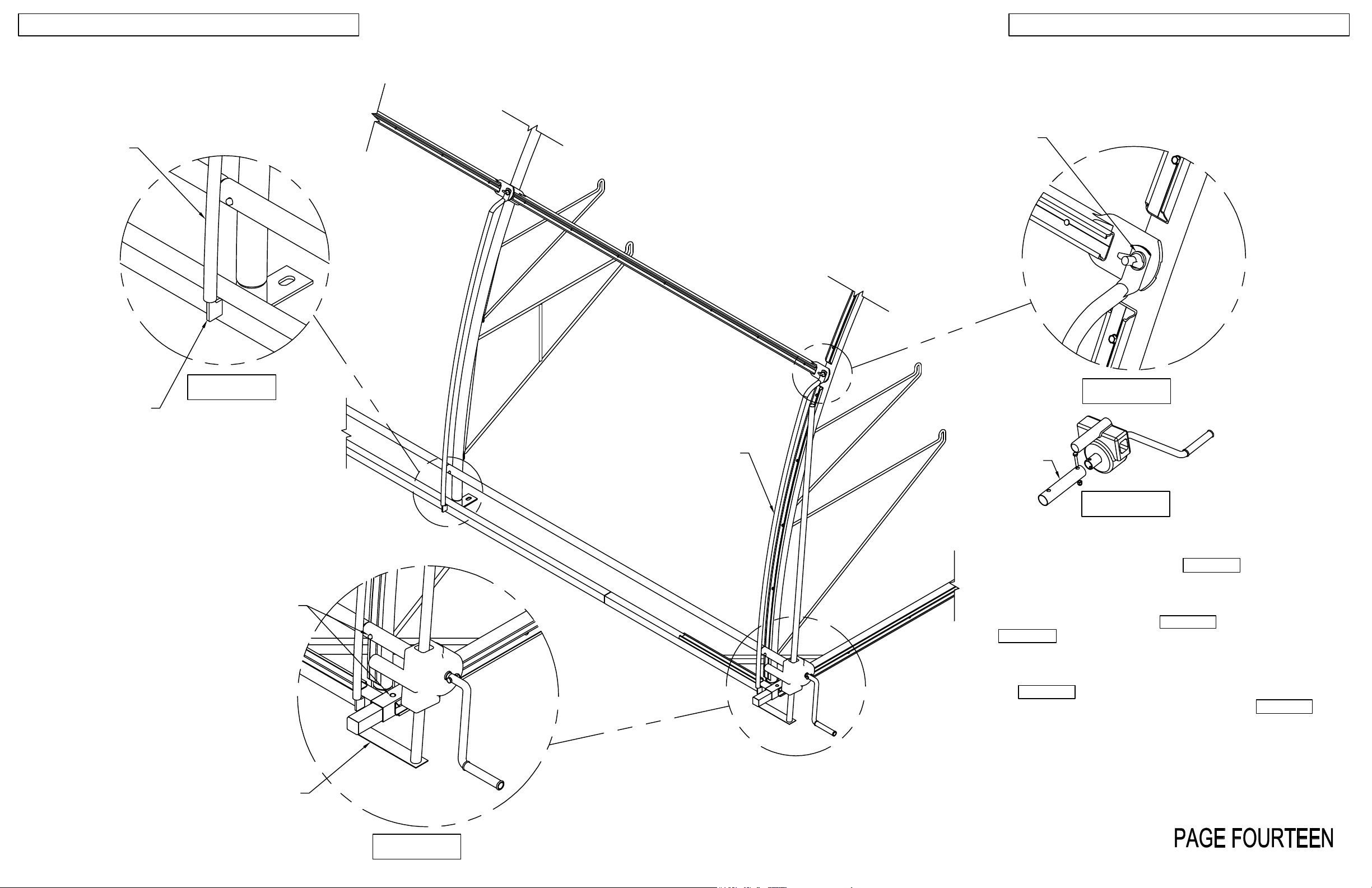
Insert KM2042 into the corner base until the snap button locks.
Repeat for the other end using KM2041. FIGURE 1
After installing the poly curtain and the gearbox guides attach the
KM2040 roll up curtain guides on every hoop frame. Slide guides
onto the guide brackets on the base FIGURE 2 , then onto the
stud. FIGURE 3 Secure to frame using wing nuts & nylon washers.
Repeat for the side of the structure not shown.
Attach the gearbox extension to the gearbox using the bolt
provided FIGURE 4 . Slide the gearbox onto the gearbox guide
and attach to roll up tube with snap button as shown in FIGURE1 .
Repeat at opposite side of structure that is not shown.
KM2042
REV: AD-130315
FIGURE 1
Page 18
POLY INSTALLATION
KOOL MART WITH ROLL-UP SIDES
1. With an equal amount of poly on all sides, start installing wiggle wire at the
Try to pick a calm day. If it is windy, it's almost impossibleto handle
Lay out the 6'6" wiggle wire around the perimeter of the structure so
at both ends of the
another worker inside the KOOL-MART at point (C), on a ladder, to
HELPFUL HINT: To avoid poly drooping between bows, instruct a
bottom left corner and continue across to the right corner. Be sure to tension
poly as you install the wigglewire.
the plastic.
2. Lift the poly to the top of the end frame and attach one section of wiggle wire
centered at the peak. Continue installing wiggle wire down the arch. Be sure
to pull the wrinkles out as you go.
3. Finish installing wiggle wire at the door header and the door jamb.
Trim excess poly.
2
3
3
1
3
1
POLY BEFORE
TRIMMING
ALWAYS TENSION
POLY WHEN APPLYING
WIGGLE WIRE
2
3
B
4
C
5
1
A
TENSIONED POLY
they are handy. Unroll the poly on the ground along the length of
the structure. Be sure you have equal overhang
greenhouse.
Place one worker at point (A) and point (B). It helps to have
help carry the poly over.
Once the poly is in position, begin installing wiggle wire sectionsat
point (1). Complete this side of the greenhouse, using the edge of
the poly as a guide. (3" to 6" overhang is adequate)
Go to the other side and install a wiggle wire section at point (2)
(center), and fan out from there. Complete this side.
helper to tension poly one section away from the person installing
the wiggle wire. You will notice the wrinkles disappear when this
method is used. When the person who is installing the wiggle wire
meets the person tensioning the poly, the tensioner can move to
the next bow.
After all wiggle wire has been installed, using a blunt object, press
all wiggle wire firmly into base to ensure it has been seated
properly.
*
WIGGLE WIRE
POLY
POLY FASTENER
Use an UP & DOWN motion
while installing wiggle wire.
ONE SECTION
Where wiggle wire ends and a
new piece begins, overlap one
section to avoid damage to the
poly.
12" WIGGLE WIRE
POLY DROOP
*
5
PERSON TENSIONING
Starting in the center of the end hoop, (3), begin installing wiggle
wire sections down to point (4). Go back to point (3), and install
wiggle wire sections to point (5). Do this on both end hoops.
After this is done, cut remaining pieces to approximately 12"
lengths. Use these in the corners (dotted lines) to reinforce the top
cover and end poly. See drawing (5)
WIGGLE WIRE
INSTALLED
WIGGLE WIRE
NOT INSTALLED
NOTE: IF THE POLY IS INSTALLED
ON A COOL DAY, IT MAY EXPAND
AS THE TEMPERATURE WARMS,
CAUSING IT TO DROOP. IT MAY
BE NECESSARY TO RETENSION
THE SHEET OF PLASTIC AT A
LATER DATE.
REV: AD-130315
 Loading...