

Page 1
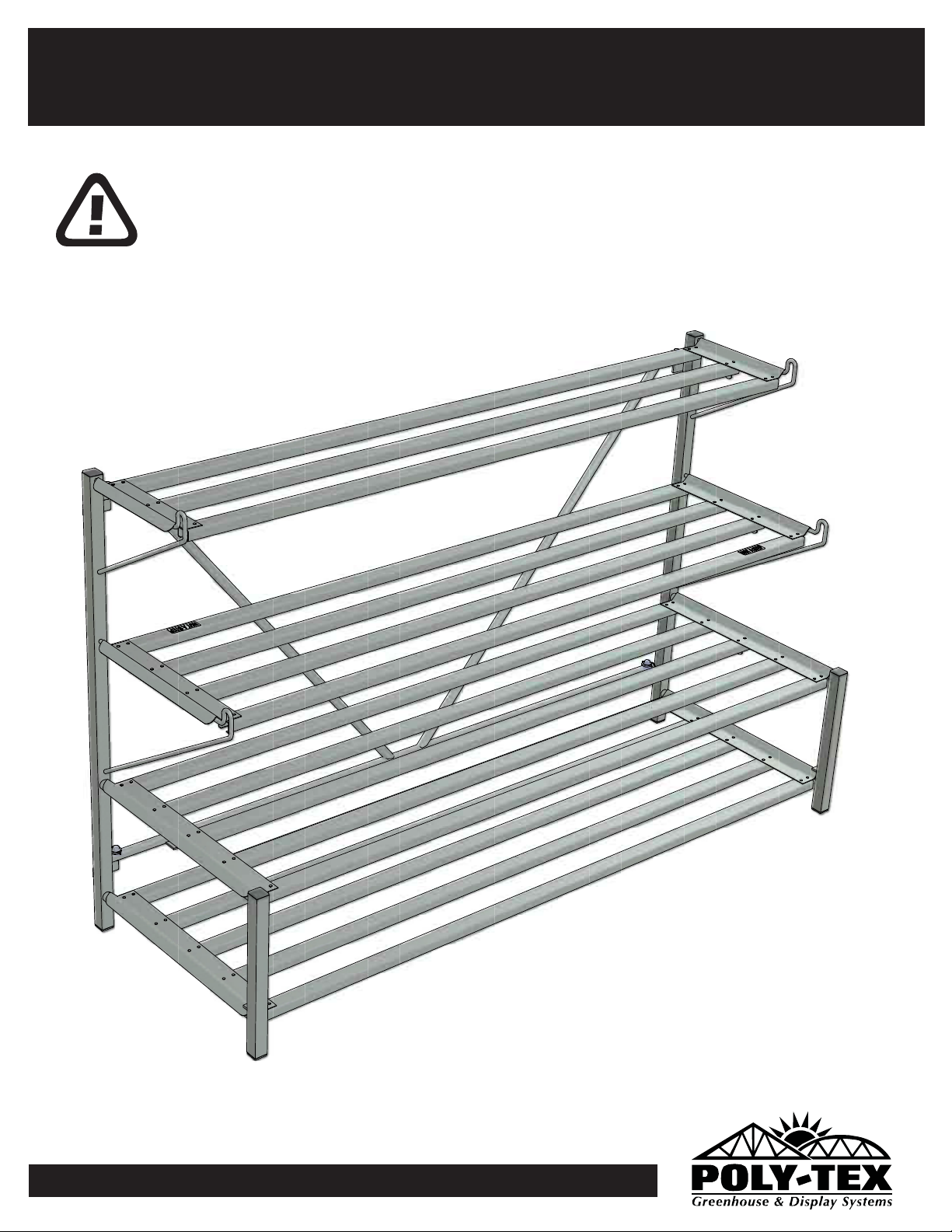
FB6000 flolding flat mate display
ASSEMBLY INSTRUCTIONS
IMPORTANT
Please read these instructions carefully before you start to
assemble this display. Save these instructions for future reference.
FB6000 v1.0.0
Page 2
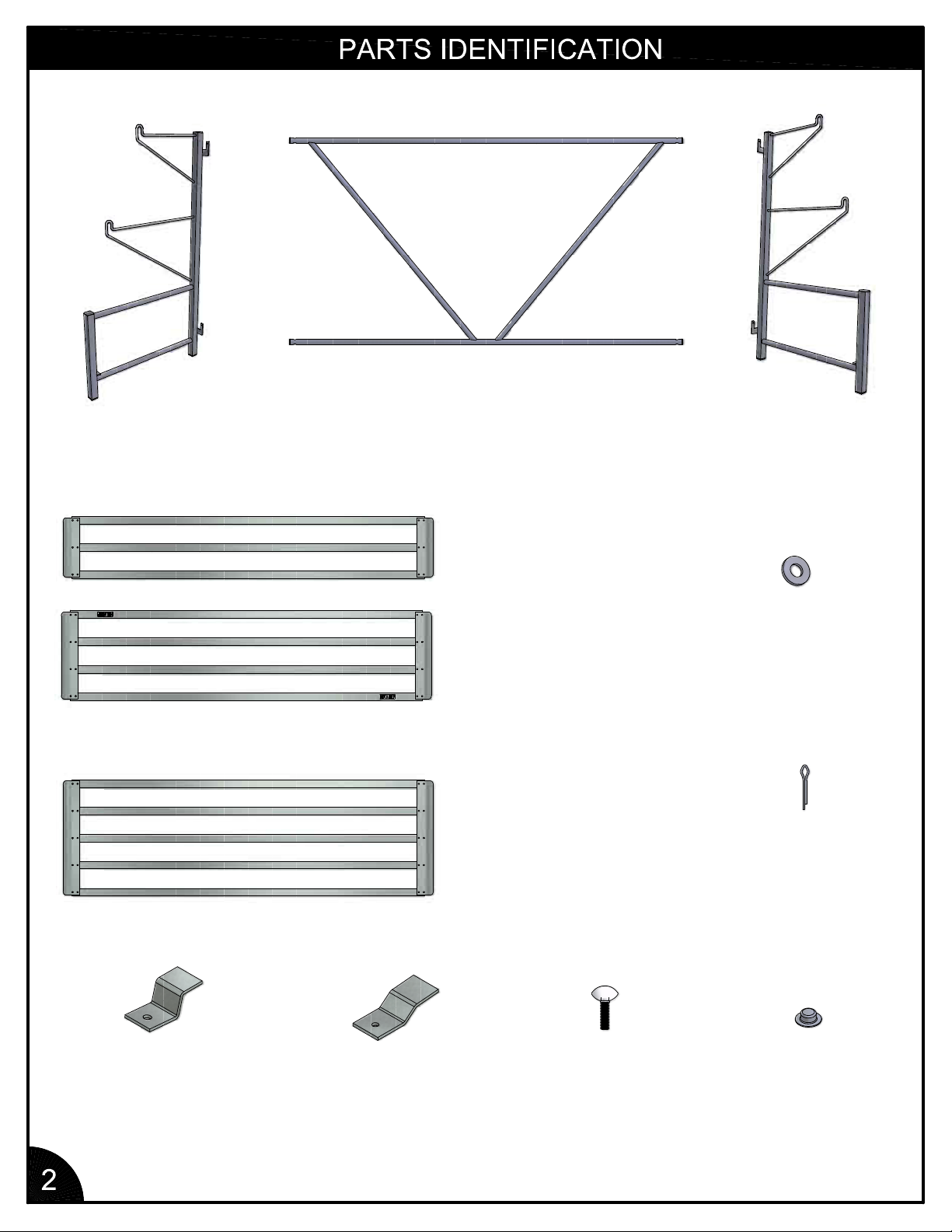
LEFT BENCH END
(FB1626)
qty (1)
STABILIZER
(FB1642)
qty (1)
12" x 6' BENCH TOP
(RF2545)
qty (1)
RIGHT BENCH END
(FB1625)
qty (1)
1'-6 x 6' BENCH TOP
(RF2554)
qty (1)
23" x 6' BENCH TOP
(RF2555)
qty (2)
FLAT WASHER
(NB1865)
qty (4)
COTTER PIN
(NB1611)
qty (4)
FLAT STACKER CLIP
(FT3200)
qty (4)
3/4" BENCH CLIP
(FT3602)
qty (2)
THUMB SCREW
(NB1924)
qty (6)
1/2" PUSH NUT
(NB1612)
qty (4)
Page 3
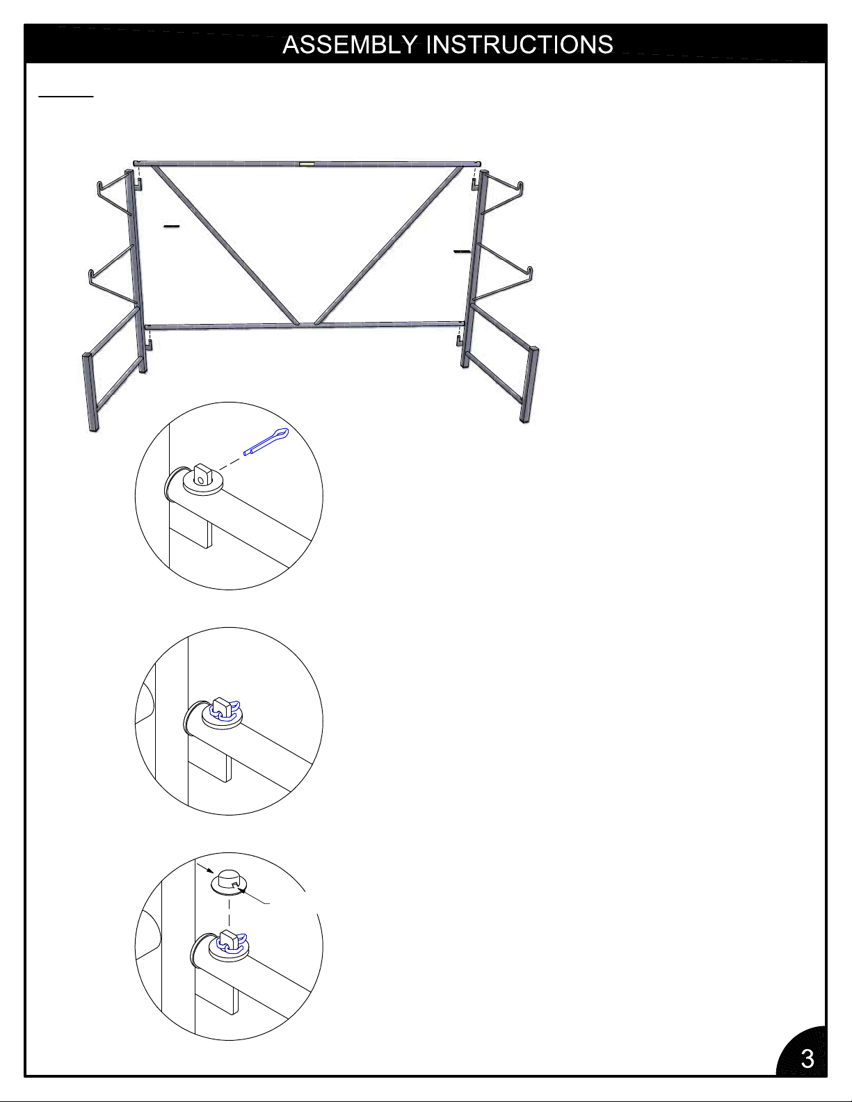
NOTE: THE FOLLOWING STEPS ON THIS PAGE ARE ONLY REQUIRED FOR INITIAL ASSEMBLY. AFTER WASHERS,
COTTER PINS, AND PUSH NUTS ARE INSTALLED, IT IS NOT NECESSARY TO REMOVE THEM FOR STORAGE. FOR
STORAGE, THE BENCH ENDS ARE SIMPLY FOLDED FLAT OVER THE STABILIZER.
1. PLACE STABILIZER ONTO
HINGES AS SHOWN.
2.PLACEFLATWASHERASSHOWNANDINSERTCOTTER
PIN THROUGH HOLE.
FRICTION
TABS
3. BEND ARMS OF COTTER PIN WITH PLIERS.
4. LINE UP FRICTION TABS ON PUSH NUT WITH THE SIDES
OF THE HINGE AND SEAT USING A HAMMER.
Page 4
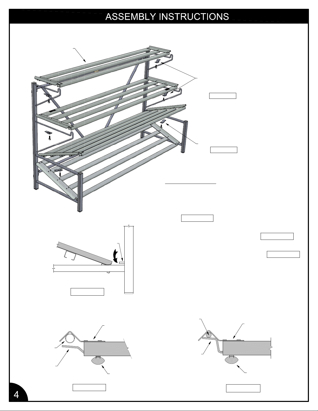
BENCH TOP
FLAT
STACKER
CLIP
SEE FIGURE 3
3/4" BENCH CLIP
SEE FIGURE 2
INSTRUCTIONS:
1. SET BENCH TOPS ONTO BENCH ENDS.
BENCH END
TUBE SUPPORT
SLIDE BENCH
TOP UNDER
HOLDING TAB
FIGURE 1
BENCH TOP
2. MAKE SURE BOTTOM BENCH TOP IS
UNDERNEATH HOLDING TAB AS SHOWN
IN FIGURE 1
3. SECURE TOP TWO BENCH TOPS WITH
FLAT STACKER CLIPS. SEE FIGURE 3
4. SECURE UPPER 23" x 6' BENCH TOP
WITH 3/4" BENCH CLIPS. SEE FIGURE 2
BENCH END
TUBE SUPPORT
BENCH TOP
FLAT STACKER CLIP
3/4" BENCH CLIP
FIGURE 2
THUMB SCREW
THUMB SCREW
FIGURE 3
Page 5
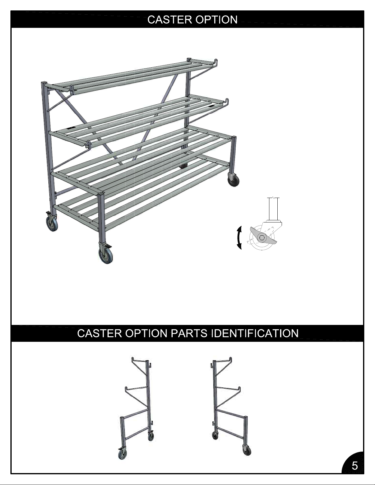
ONCE DISPLAY IS IN PLACE,
ALL CASTERS MUST BE LOCKED
TO PREVENT MOVEMENT. THE
BRAKE IS ACTIVATED BY ROTATING
THE LEVER FROM THE "OFF"
POSITION TO THE "ON" POSITION.
LEFT BENCH END
WITH CASTERS
(FB1631)
qty (1)
RIGHT BENCH END
WITH CASTERS
(FB1630)
qty (1)
Page 6
Do not climb, sit on, or use this product as a ladder due to possible injuries.
Do not place or install electrical items on this product. Wet conditions are typical and electrical
shock is possible.
Do not place this product on a slope that exceeds 10 degrees.
If your display does not have casters, do not move this display after product is in place. Damage
to display and injuries may occur.
If your display does have casters, once in place, lock all casters to prevent movement.
To remove loose soil and debris, simp
ly spray the soiled areas with a garden hose.
Prior to storage, all surfaces of this product should be sprayed down with water and allowed to dry
completely.
Store folding frames in a flat postion.
Hammer, Pliers
Limited Warranty
Poly-Tex, Inc. warrants its products to be free from defects in material and workmanship for a
period of (1) year from date of invoice. This warranty is provided to the original purchaser of the
product and is not transferable. Poly-Tex does not warrant parts not manufactured by Poly-Tex,
but does assign any transferable manufacturer or supplier warranties. Should any defect be
found, full repair or replacement will be rendered to the customer at no cost followi
ng inspection
by a Poly-Tex representative and the return of the defective product to our Castle Rock, MN
factory. Expenses for removal or reinstallation of defective products will not be covered by the
warranty.
POLY-TEX SHALL NOT BE HELD RESPONSIBLE FOR ANY SPECIAL OR
CONSEQUENTIAL DAMAGES, OR FOR ANY DELAY IN PERFORMANCE OF THIS
WARRANTY BEYOND OUR CONTROL. THIS WARRANTY IS EXCLUSIVE AND IN LIEU OF
ALL OTHER WARRANTIES WHETHER IMPLIED, WRITTEN OR ORAL INCLUDING
THE
WARRANTIES OF MERCHANTABILITY AND FITNESS FOR A PARTICULAR PURPOSE.
hiswarrantydoesnotcoverdamagefromcustomer abuse, misuse, improper installation,
T
customer modifications, customer negligence in performing normal maintenance, damage
resulting from acts of nature.
Contact information
Poly-Tex, Inc. PO Box 458
27725 Danville Ave Castle Rock, MN 55010
Toll free (800) 852-3443 Fax (651) 463-2479
www.poly-tex.com
 Loading...