

Page 1

CC5000 Checkout Center
ASSEMBLY INSTRUCTIONS
IMPORTANT
Please read these instructions carefully before you start to
assemble this display. Save these instructions for future reference.
CC5000 v1.0.0
Page 2
SAFETY GUIDELINES
Read before assembling the structure
Warning
This structure is intended to be self-supporting once constructed with all sheathing, sheeting,
bracing, cables, or cloth in place, and secured to the foundation as shown in the manual.
Stability during construction, from winds and loads imposed during erection, is the sole
responsibility of the installer. Observe safety codes required by your jurisdiction, as well as
relevant safety practices for working at heights. Consider the risk of electrical shock from
overhead lines or electrical storms. We recommend a licensed electrician perform any electrical
work. Eye protection is recommended under all circumstances and hearing protection is
recommended when cutting components with power tools.
Danger: No part of this structure is engineered to function as an anchorage point for a fall
arrest system. Use a safety net or work from a safe work platform (i.e. scaffolding).
Overview of assembly procedure
While each structure and site is unique, the two most common methods for installing such
structures are a tilt-up method (where frames are assembled on the ground and tilted onto
ground stakes or anchor rods using ropes or lifts) or installing posts first with the roof structure
lifted and secured into place second. Both methods are dangerous when attempted by the
unskilled. If you do not feel confident installing the structure, we suggest you hire a general
contractor, carpenter, or similar licensed business familiar with temporary bracing and
construction to assemble, install and erect your structure.
Foundations
Temporary structures are not intended for permanent attachment to a foundation. The plates on
the posts should be weighted down with a minimum of 900 pounds per post.
Danger: Wind can catch components and pull you off a work platform or ladder, resulting
in a potentially deadly fall. Select a calm day for work.
Page 3
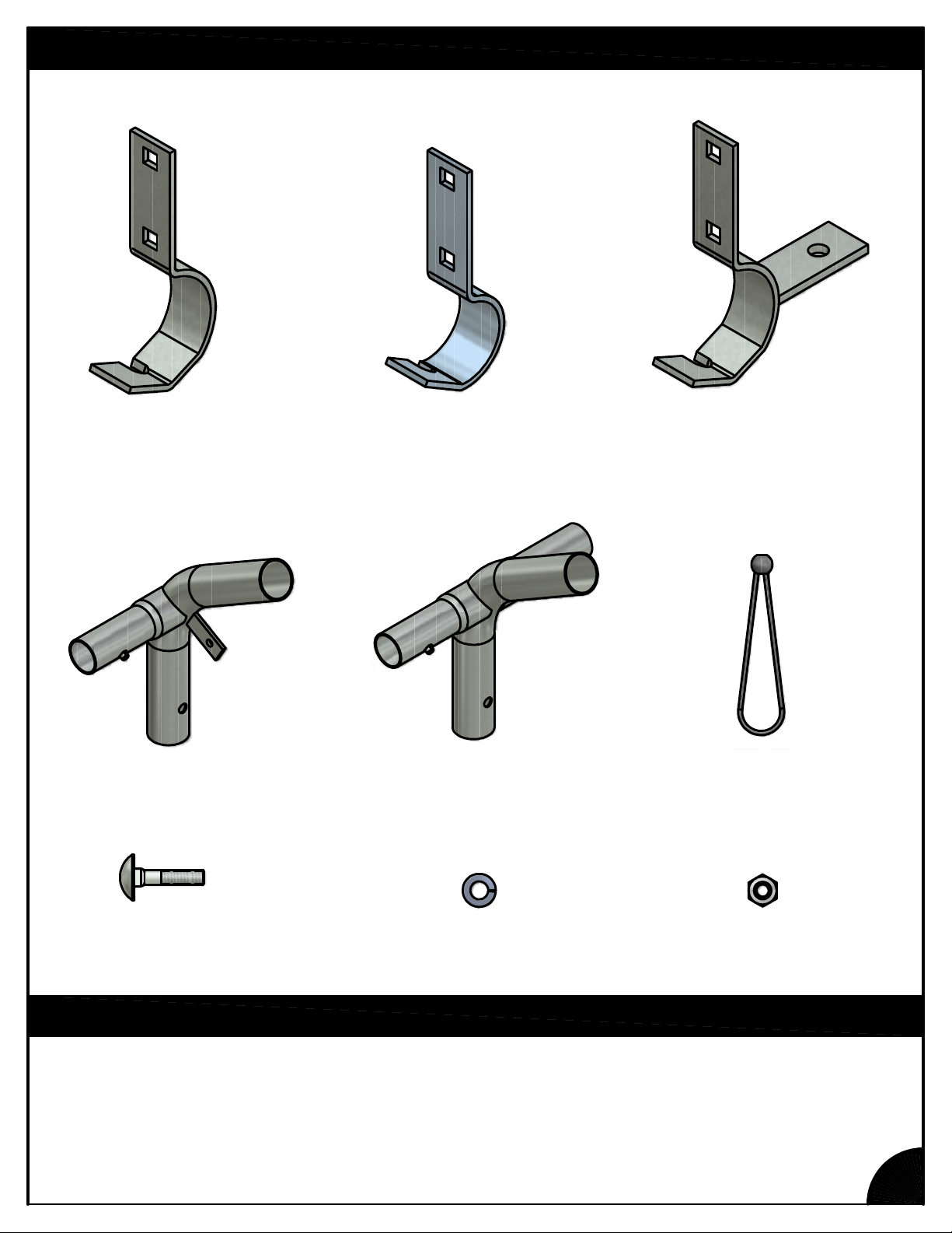
PARTS IDENTIFICATION
FT2079
LONG SPEED HOOK (2")
FT7000
3-WAY FITTING (2")
FT2080
LONG SPEED HOOK (1.66")
FT7001
4-WAY FITTING (2")
FT7002
2-WAY LONG SPEED HOOK (2")
PT2521
BUNGEE BALL
NB1832
5/16" x 1-1/4"
CARRIAGE BOLT
5/16" wrench
NB1862
5/16" LOCK WASHER
TOOLS & EQUIPMENT REQUIRED
NB1872
5/16" HEX NUT
2
Page 4
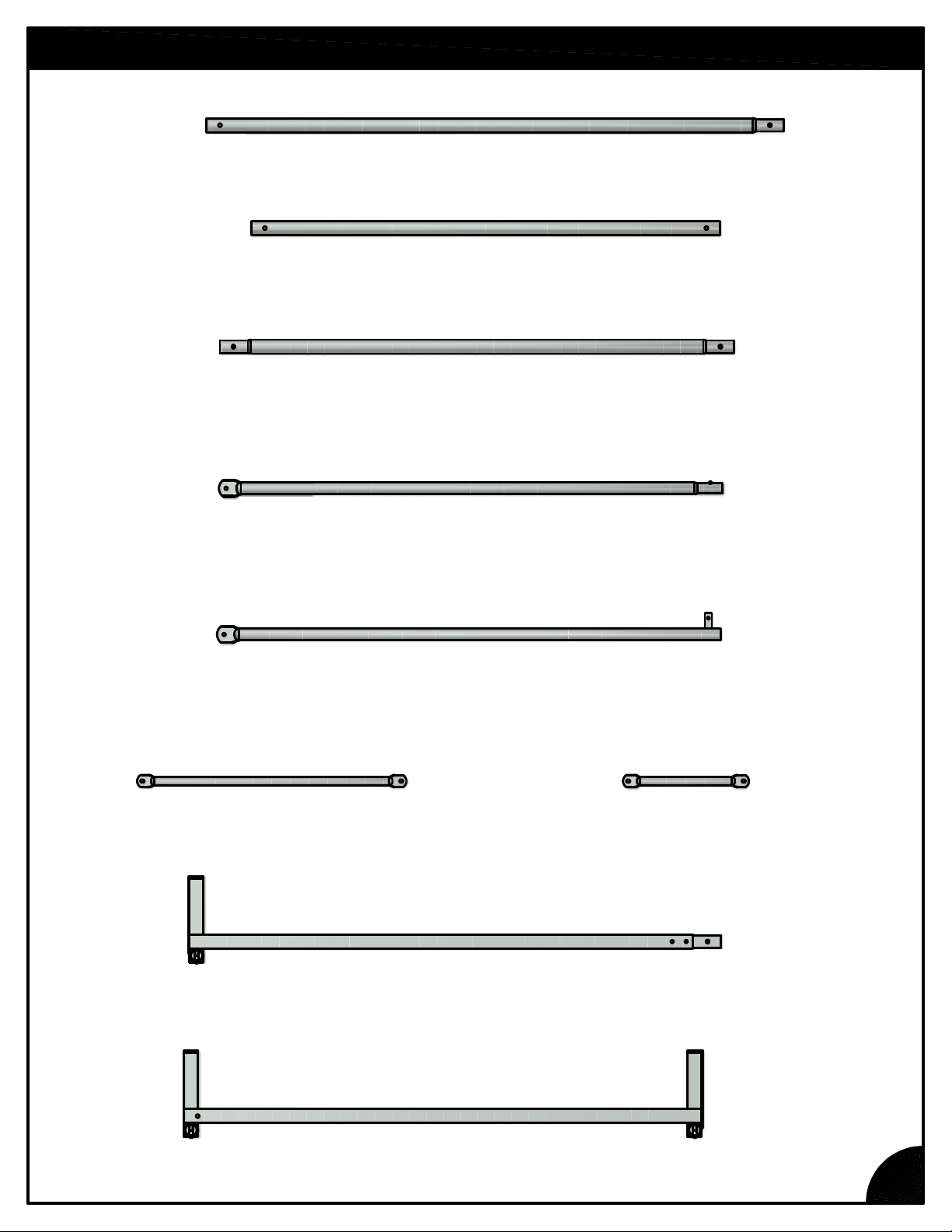
PARTS IDENTIFICATION
CH9001
2" VERTICAL POST
CH9002
2" HORIZONTAL TUBE
CH9003
2" PEAK TUBE
CH9006
VERTICAL END
CH9004
HORIZONTAL END, MALE
CH9005
HORIZONTAL END, FEMALE
CH9007
CORNER BRACE
CH9008
BASE RAIL WELDMENT, MALE
CH9009
BASE RAIL WELDMENT, FEMALE
3
Page 5
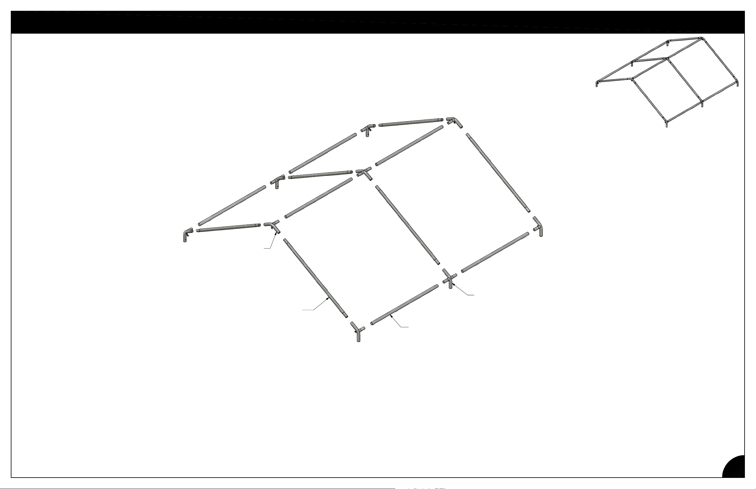
ROOF ASSEMBLY
3-WAY
FITTING
(6)
PEAK TUBE
(6)
4-WAY
FITTING
(3)
HORIZONTAL
TUBE
(6)
1. Assemble components as shown, making sure that all pieces snap into place.
4
Page 6
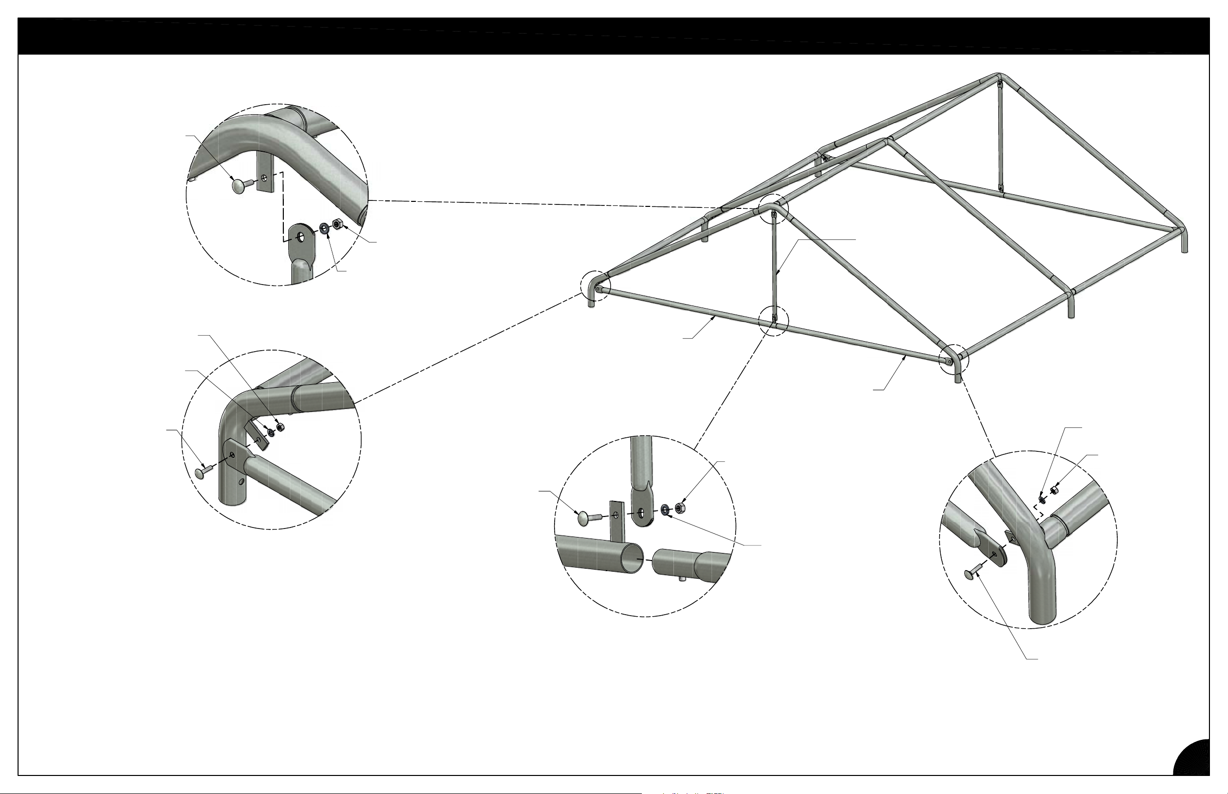
CARRIAGE
BOLT
HEX NUT
LOCK
WASHER
ROOF ASSEMBLY
VERTICAL
TUBE
(2)
HEX NUT
LOCK
WASHER
CARRIAGE
BOLT
CARRIAGE
BOLT
HORIZ. END, FEMALE
(2)
HORIZ. END, MALE
HEX NUT
LOCK
WASHER
(2)
LOCK
WASHER
HEX NUT
2. Fasten end horizontals and end vertical using hardware as shown. Repeat for opposite end.
CARRIAGE
BOLT
5
Page 7
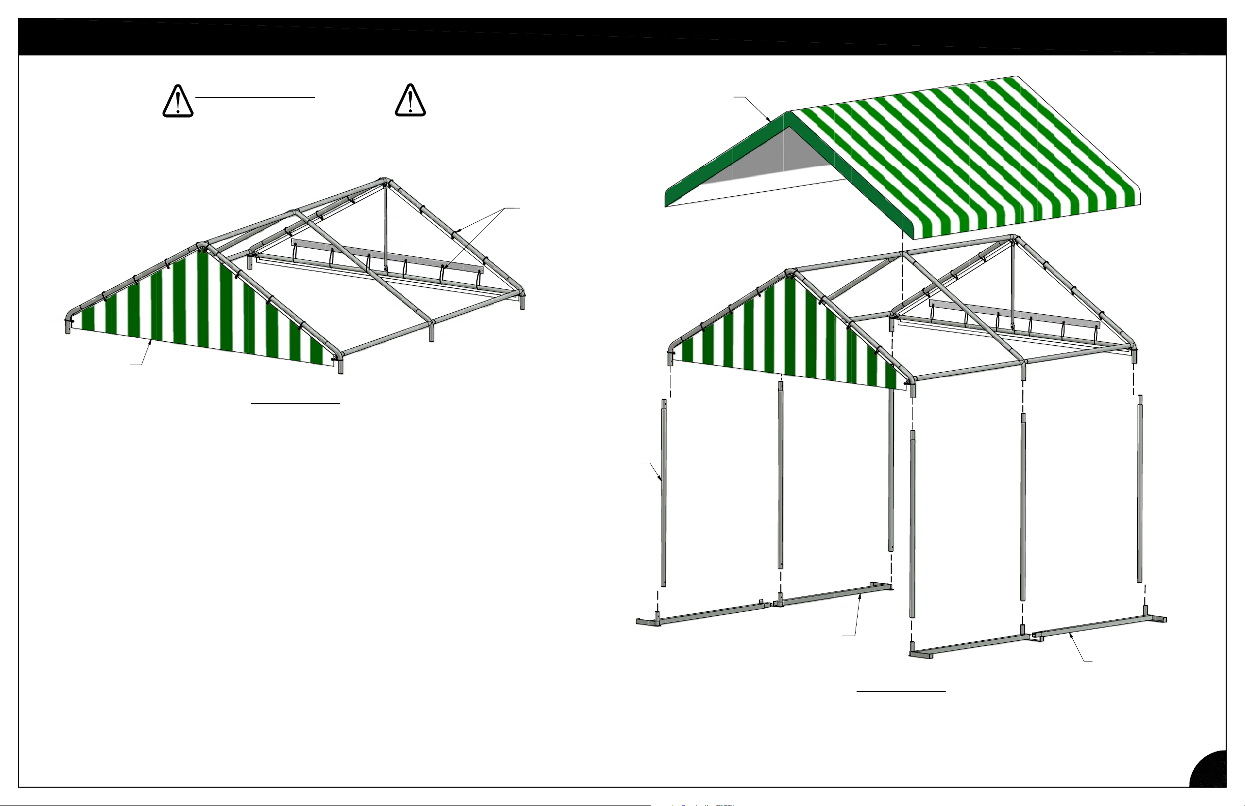
FRAME ASSEMBLY
END
PANEL
(2)
IMPORTANT NOTE:
WEAR EYE PROTECTION WHEN
INSTALLING BUNGEE BALLS.
TOP
COVER
BUNGEE
BALL
FIGURE 1
1. Install vinyl end panels and secure with bungee balls. (Figure 1)
VERTICAL
POST
(6)
BASE RAIL, FEMALE
(2)
BASE RAIL, MALE
(2)
FIGURE 2
2. Position top cover but do not secure with bungee balls until later. Install vertical posts
and base rails as shown, making sure that all pieces snap into place. (Figure 2)
6
Page 8
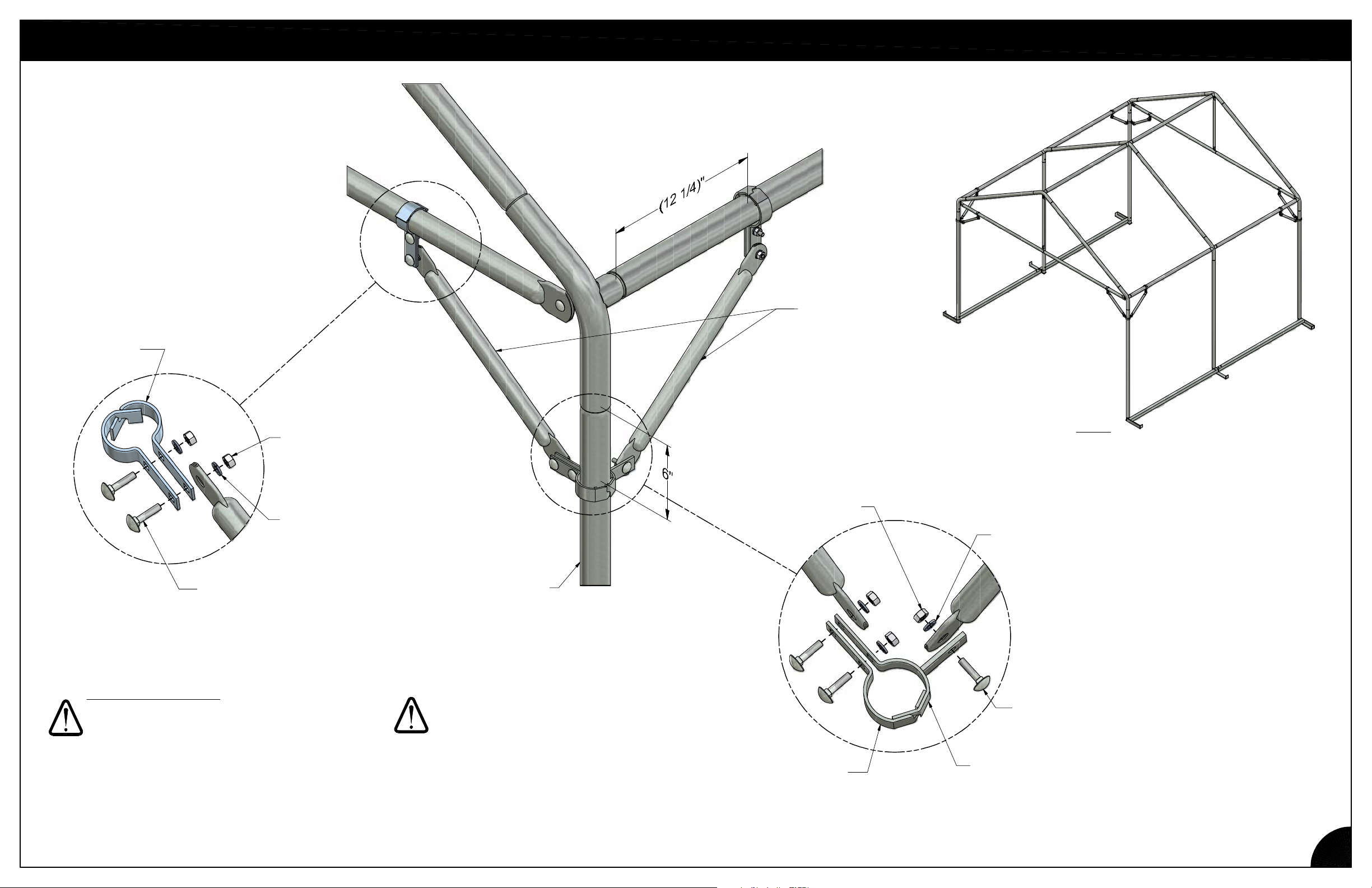
1.66" LONG
SPEED HOOK
(2)
CORNER DIAGONAL BRACES
CORNER
BRACES
HEX NUT
(2)
LOCK WASHER
(2)
CARRIAGE
BOLT
(2)
IMPORTANT NOTE:
ALL COMPONENTS ATTACHED TO LONG
SPEED HOOKS MUST BE MOUNTED ON THE
OUTSIDE OF THE HOOKS. NEVER INSTALL
COMPONENTS BETWEEN HOOKS.
VERTICAL
POST
HEX NUT
(3)
2" LONG
SPEED HOOK
NOTE:
SHADE PIECES NOT SHOWN
FOR CLARITY.
LOCK
WASHER
(3)
CARRIAGE
BOLT
(3)
2-WAY LONG
SPEED HOOK
1. Install diagonal braces as shown to ensure proper support of structure.
Level vertical posts then tighten bolts securely.
7
Page 9
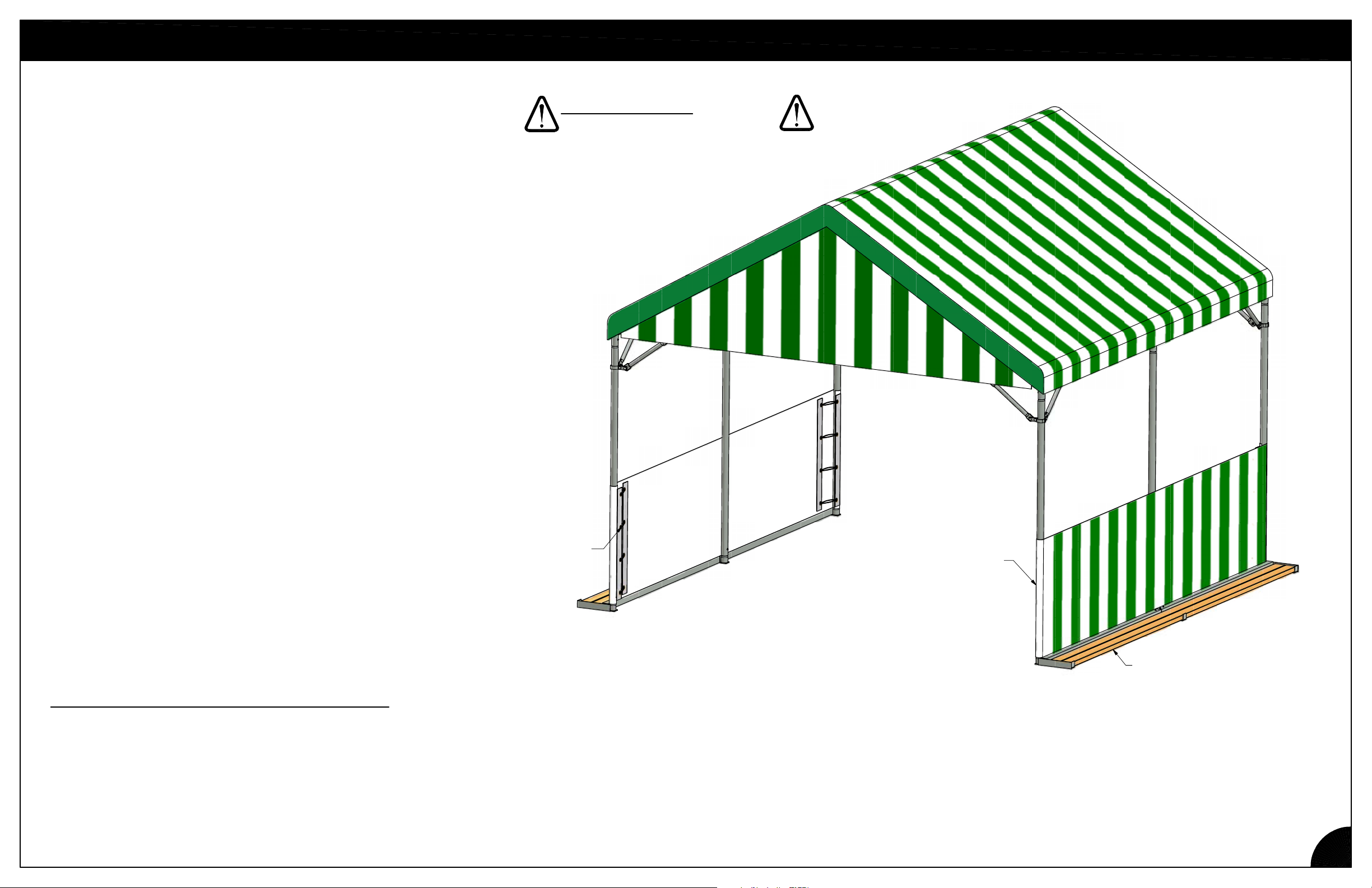
SIDE SKIRT AND COVER ATTACHMENT
IMPORTANT NOTE:
WEAR EYE PROTECTION WHEN
INSTALLING BUNGEE BALLS.
1. Secure top cover with bungee balls.
2. Install side skirts using bungee balls as shown.
3. Put 2x4's on base. Position hold down weights evenly.
ADDITIONAL HOLD DOWN MATERIALS REQUIRED
8 - 2" x 4" x 6'-0" LUMBER
or
4 - 2" x 4" x 12'-0" LUMBER
A quantity of dead weight such as cinder blocks or
landscape blocks. Dead weight items need to be
stackable. Do not use bagged goods such as water
conditioning salt.
BUNGEE
BALL
SIDE SKIRT
(2)
2x4's
8
Page 10
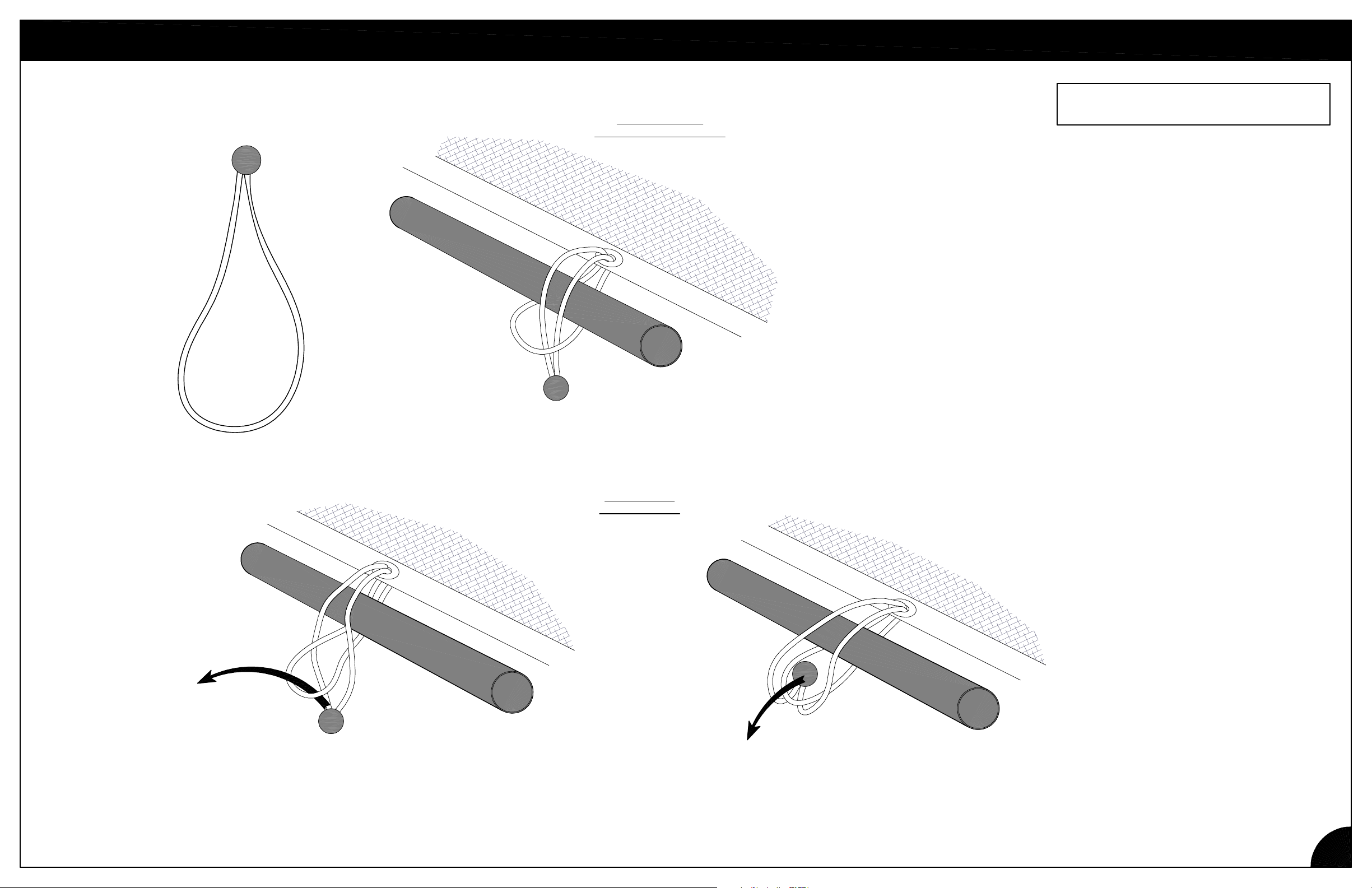
BUNGEE BALL
BUNGEE INSTALLATION
WRAP AROUND
TYPICAL INSTALLATION
A BUNGEE MAY SLIP OFF IF FABRIC IS NOT TAUT.
OCCASIONALLY CHECK YOUR INSTALLATION TO
ENSURE ALL BUNGEES REMAIN ATTACHED.
SEE ALTERNATE ATTACHMENTSBELOW, WHICH
MAY HELP.
ONCE IN PLACE, MOVE BUNGEE SO BALL IS NEAR
GROMMET.
WHEN REINSTALLING, INSPECT BUNGEE BALLS
FOR WEAR OR DAMAGE. DO NOT USE
DAMAGED BUNGEE BALLS.
THROUGH LOOP
PASS THE LOOP THROUGH THE BALL
(OPPOSITE OF THE TYPICAL)
ALTERNATE
INSTALLATION
PULL TIGHT
THEN FORCE THE BALL BEHIND
THE LOOP
9
Page 11
SAFETY GUIDELINES
Do not climb, sit on, or use this product as a ladder. Injuries may occur.
Do not place or install electrical items on this product. Electric shock may occur.
Do not place this product on a slope that exceeds 1/4" per foot.
Do not overload structure with hanging plants that weaken the structure's resistance to wind.
CARE & MAINTENANCE
Periodically (at least every two years) inspect items subject to wear for signs of deterioration,
weakening, or significant corrosion.
Limited Warranty
Poly-Tex, Inc. warrants its products to be free from defects in material and workmanship for a
period of (1) year from date of invoice. This warranty is provided to the original purchaser of the
product and is not transferable. Poly-Tex does not warrant parts not manufactured by Poly-Tex,
but does assign any transferable manufacturer or supplier warranties. Should any defect be
found, full repair or replacement will be rendered to the customer at no cost following inspection
by a Poly-Tex representative and the return of the defective product to our Castle Rock, MN
factory. Expenses for removal or reinstallation of defective products will not be covered by the
warranty.
POLY-TEX SHALL NOT BE HELD RESPONSIBLE FOR ANY SPECIAL OR
CONSEQUENTIAL DAMAGES, OR FOR ANY DELAY IN PERFORMANCE OF THIS
WARRANTY BEYOND OUR CONTROL. THIS WARRANTY IS EXCLUSIVE AND IN LIEU OF
ALL OTHER WARRANTIES WHETHER IMPLIED, WRITTEN OR ORAL INCLUDING THE
WARRANTIES OF MERCHANTABILITY AND FITNESS FOR A PARTICULAR PURPOSE.
This warranty does not cover damage from customer abuse, misuse, improper installation,
customer modifications, customer negligence in performing normal maintenance, damage
resulting from acts of nature.
Contact information
Poly-Tex, Inc. PO Box 458
27725 Danville Ave Castle Rock, MN 55010
Toll free (800) 852-3443 Fax (651) 463-2479
www.poly-tex.com
 Loading...