

Page 1

Operator’s Manual
Model 4100 and 4200 Series Liquid-to-Liquid
Coolers
110-497 09 March 2020
Find Quality Products Online at: sales@GlobalTestSupply.com
www.GlobalTestSupply.com
Page 2

Table of Contents
Introduction ...............................................................................................................................................................3
General Safety Information .....................................................................................................................................3
Safety Recommendations .......................................................................................................................................4
Unpacking Your Liquid-to-Liquid Cooler .................................................................................................................4
Regulatory and Compliance Testing .......................................................................................................................4
Contents ..................................................................................................................................................................4
Controls and Components ......................................................................................................................................5
Front Control Panel .................................................................................................................................................5
Rear Panel ..............................................................................................................................................................5
Installation and Startup ............................................................................................................................................6
Site Requirements ..................................................................................................................................................6
Ambient Temperature and Relative Humidity .....................................................................................................6
Location ...............................................................................................................................................................6
Clearance ............................................................................................................................................................6
External Piping ........................................................................................................................................................6
General Considerations .......................................................................................................................................6
Process Fluid Connections ..................................................................................................................................7
Facility Water Connections ..................................................................................................................................7
Process Coolant ......................................................................................................................................................7
Electrical Power ......................................................................................................................................................8
Main Power Connection ......................................................................................................................................8
Optional Serial Output (RS-232) .............................................................................................................................8
Optional Dry Contact Remote ON/OFF ..................................................................................................................8
Startup .....................................................................................................................................................................9
Normal Operation .................................................................................................................................................. 10
Electrical Power ................................................................................................................................................... 10
Selecting the Temperature Unit ........................................................................................................................... 10
Displaying and Adjusting the Set Point ................................................................................................................ 10
Setting Operational Parameters ........................................................................................................................... 11
High Temperature Limit (HL) ............................................................................................................................ 11
Low Temperature Limit (LL) ............................................................................................................................. 11
High Ambient Temperature Limit (HA) ............................................................................................................. 12
Maximum Fluid Pressure (FP) .......................................................................................................................... 12
Minimum Flow Rate (FL) .................................................................................................................................. 12
Calibration Offset (°C) ...................................................................................................................................... 13
Flow Calibration (Fc) ........................................................................................................................................ 13
Baud Rate (PC) ................................................................................................................................................ 14
Adjusting the High Pressure Bypass Setting ..................................................................................................... 14
Display, Alarm and Error Messages .................................................................................................................... 15
Enabling / Disabling the Local Lockout .............................................................................................................. 17
Routine Maintenance and Troubleshooting ....................................................................................................... 18
Routine Maintenance ........................................................................................................................................... 18
Air Vents ........................................................................................................................................................... 18
Process and Facility Line Strainers .................................................................................................................. 18
In-Line Fluid Filter ............................................................................................................................................. 18
Fluid Level ........................................................................................................................................................ 18
Software Version .............................................................................................................................................. 18
Draining the Unit .................................................................................................................................................. 19
Troubleshooting Chart ......................................................................................................................................... 19
Technical Information ........................................................................................................................................... 20
Performance Specifications ................................................................................................................................. 20
Cooling Capacity vs. Facility Water Flow Rate .................................................................................................... 21
Wiring and Flow Diagram ..................................................................................................................................... 22
110-497 1
Find Quality Products Online at: sales@GlobalTestSupply.com
www.GlobalTestSupply.com
Page 3

Reservoir Fluids ................................................................................................................................................... 23
Replacement Parts ................................................................................................................................................ 24
PolyScience Fluids ................................................................................................................................................ 24
Optional Serial Output (RS-232) ........................................................................................................................... 25
Equipment Disposal (WEEE Directive) ................................................................................................................ 26
Service and Technical Support ............................................................................................................................ 26
Warranty ................................................................................................................................................................. 27
110-497 2
Find Quality Products Online at: sales@GlobalTestSupply.com
www.GlobalTestSupply.com
Page 4

Introduction
This symbol alerts you to wide range of potential dangers. When attached to the unit, this symbol draws
attention to the relevant section of the operator’s manual.
This symbol advises
This symbol marks information that is particularly important
This symbol indicates alternating current.
/
These symbols on the Power Sw
This symbol on the Power Switch indicates that it places the unit in a standby mode. It DOES NOT fully disconnect the unit
from the power supply.
This symbol indicates a protective conductor terminal.
Your Liquid-to-Liquid Cooler is a quiet and efficient heat removal system. Process cooling is provided by pumping
facility water (or other liquid cooling medium) through a liquid-to-liquid brazed plate heat exchanger to cool the
process fluid loop. Heat is rejected to the facility fluid and temperature controlled by a proportional valve that
bypasses a portion of the process fluid around the heat exchanger. Because the facility water and process fluid
remain separate, there is no risk of equipment damage due to facility water contamination.
Key features:
• Powerful liquid-to-liquid coolin g
• Quiet, energy-efficient operation
• Microprocessor control
• Digital set and read (°C or °F)
It will take you very little time to get your Liquid-to-Liquid Cooler installed and running. This manual is designed to
guide you quickly through the process. We recommend that you read it thoroughly before you begin.
General Safety Information
When installed, operated, and maintained according to the directions in this manual and common safety
procedures, your Liquid-to-Liquid Cooler should provide safe and reliable heat removal. Please ensure that all
individuals involved in the installation, operation, or m aintenance of this unit read this manual thoroughly prior to
working with the unit.
you of danger from electricity or electric shock.
.
itch / Circuit Breaker indicate that they place the main power supply ON / OFF.
Read all instructions pertaining to safety, set-up, and operation.
Proper operation and maintenance is the user’s responsibility.
110-497 3
Find Quality Products Online at: sales@GlobalTestSupply.com
www.GlobalTestSupply.com
Page 5

Safety Recommendations
WARNING:
• Always connect the power cord on this unit to a grounded (3-prong) power outlet. Make certain that the
outlet is the same voltage and frequency as your unit.
• Never operate the unit with a damaged power cord.
• Always turn the unit OFF and disconnect Mains power before performing any maintenance or service.
CAUTION: To ensure that internal damage does not occur during shipping or storage, water must be drained
from all parts of the system or an antifreeze solution added
CAUTION
regarding the safe lifting and relocation of heavy objects.
To prevent injury to personnel and/or damage to property, always follow your workplace’s safety procedures when
operating this equipment. You should also comply with the following safety recommendations:
.
Unpacking Your Liquid-to-Liquid Cooler
Your Liquid-to-Liquid Cooler is shipped in a special carton. Retain the cart on and all packing materials until the
unit is completely assembled and working properly. Set up and run the unit immediately to confirm proper
operation. Beyond one wee k, y our un it may b e warra nty re paired, but not replaced. If the uni t is damaged or does
not operate properly, contact the transportation company, file a damage cl aim and contact the c ompany where
your unit was purchased immediately.
: Keep unit upright when moving. Be sure to follow your company’s procedures and practices
Regulatory and Compliance Testing
Canada USA (60Hz units)
CAN/CSA C22.2 No. 61010-1-12 — Safety Requirements for Electrical Equipment for Measurement, Control
and Laboratory Use, Part I: General Requirements.
UL Std No. 61010-1 (2012) — Safety Requirements for Electrical Equip ment for Measurement, Control and
Laboratory Use - Part I: General Requirements.
CE (50Hz units)
Machinery Directive 2006/42/EC
EC Electromagnetic Compatibility Directive 2014/30/EU
IEC 61010-1 / EN 61010-1:2010
IEC 61326:2012 / EN 61326:2013
RoHS Directive 2011/65/EU
Highly Accelerated Life Test (HALT) and Vibration Tests per ASTM D4169-8 (All units )
Contents
The following items have been included with your Liquid-to-Liquid Cooler:
• Liquid-to-Liquid Cooler
• Operator’s Manual
• IEC Power Cord
Find Quality Products Online at: sales@GlobalTestSupply.com
110-497 4
www.GlobalTestSupply.com
Page 6

Controls and Components
Temperature Display
Select/Set Knob
Power Button
Pressure / Flow Rate Display
Units / Menu Select Button
Reservoir Cap and Fluid Filter Port
(top rear)
Process Water In
Facility Water In
Circuit Breaker /
Power Switch
IEC Power Connection
Pressure / Flow Rate Units
Facility Water Out
Process Water Out
Temperature Units
Communication Port
(optional Remote
ON/OFF)
RS-232 Connection
(optional)
Front Control Panel
Rear Panel
Find Quality Products Online at: sales@GlobalTestSupply.com
110-497 5
www.GlobalTestSupply.com
Page 7

Installation and Startup
WARNING:
NOTE:
evel below that of the equipment being cooled. As
long as the process remains closed, overflow will not occur when adding cooling f
Liquid
Cooler reservoir.
WARNING:
Be sure all power is off before proceeding.
Site Requirements
Ambient Temperature and Relative Humidity
The Liquid-to-Liquid Cooler is designed for indoor installation in ambient temperatures between 5° and 35°C (41°
and 95°F); relative humidity should not exceed 80% (non-condensing).
Location
The Liquid-to-Liquid Cooler should be installed on a strong, level surface. Do not place it where corrosive fumes,
excessive moisture, excessive dust, or high room temperatures are present.
For ease of positioning and maneuverability, the unit is supplied with casters. The front wheels can be locked to
keep it in place while in use.
To help prevent voltage drops, position the Liquid-to-Liquid Cooler as close as possible to the power distribution
panel. Avoid voltage drops by using a properly grounded power outlet wired with 14 gauge or larger diameter
wire. The use of an extension cord is not recommended.
The Liquid-to-Liquid Cooler may be located at a l
luid to the Liquid-to-
Clearance
Adequate clearance should be allowed on the front, sides, and rear of the Liquid-to-Liquid Cooler for access to
the reservoir tank, electrical cabinet, and external piping connections.
External Piping
All facility water connections must be made by a licensed plumber.
General Considerations
• Take care when selecting hoses and connections for the Liquid-to-Liquid Cooler. All external piping, tubing,
or hoses should be run full size to limit the potential for external pressure drops. Quick-connect fittings may
be used, but they can cause substantial pressure drops.
• Materials of construction should be compatible with the fluid being used as well as the temperature and
pressure at which the unit will operate.
• Where applicable, always use a back-up wrench when making piping connections to the Liquid-to-Liquid
Cooler.
• Pressure Ratings – Hoses should be able to withstand the greatest pressure they will encounter. 150 psi
(344.7 kPa) is recommended. Unit will alarm if default value of 80 psi (551.6 kPa) is exceeded; maximum
setting is 100 psi (689.5 kPa).
• Flexible Tubing – Avo id tubing that will expan d and increase fluid volume when operating at the desired
pressure.
• Hose Diameter – The fittings on the Liquid-to-Liquid Cooler’s process and facility water fluid inlets and
outlets are female 0.5 inch NPT.
• Facility Water – Should be clean and well maintained. Ideally, the facility water should be tested monthly to
ensure a pH level between 7.2 and 7.8. Add algaecide if algae growth is present.
110-497 6
Find Quality Products Online at: sales@GlobalTestSupply.com
www.GlobalTestSupply.com
Page 8

Process Fluid Connections
WARNING: The incoming cooling water pressure should be limited to 125 psi (861.8 kPa) maximum.
NOTE:
whenever the unit is tur
WARNING:
equirements. Caustic,
corrosive, or flammable fluids should never be used. Read the safety data sheet for the process fluid being
used carefully before filling reservoir.
WARNING:
DO NOT use automotive
antifreeze as the additives may be harmful to the Liquid
stainless steel, EPDM rubber, nylon, and PVC).
Connect the process fluid inlet on the equipment to be cooled to the process fluid outlet on the Liquid-to-Liquid
Cooler. Connect the process fluid outlet on the equipment to be cooled to the process fluid inlet on the Liquid
Temperature.
Facility Water Connections
The cooling water supply may be from a chiller, city tap water, or a cooling tower. The cooling water supply should
be connected to the facil ity water inlet on the Liquid-to-Liquid Co oler. The facility water outlet on the Liquid-toLiquid Cooler should be connected to t he appropriate return or drain, as require d. The incoming water pressure
should be limited to 125 psi (861.8 kPa) .
A solenoid valve inside the Liquid-to-Liquid Cooler shuts off facility water fluid flow
ned OFF or if an alarm condition is detected that turns the pump OFF.
Process Coolant
See Technical Information, Reservoir Fluids (page 23) for additional information.
Suitable Fluids
Only use fluids that satisfy safety, health, and equipment compatibility r
Operation below 15°C (59°F) requires antifreeze in the circulation fluid.
-to-Liquid Cooler’s wetted parts (brass, bronze,
The Liquid-to-Liquid Cooler is designed to accommodate a variety of coolant fluids (water, glycol mixtures, etc).
For most applications above 15°C (59°F), distilled water is satisfactory. For operation at or below 15°C (59°F), the
unit must be protected with an antifreeze solution. Ethylene glycol (laboratory grade) and distilled water in a 50/50
mixture is satisfactory from +15° to -15°C (59° to 5°F). Select a fluid that is compatible with the Liquid-to-Liquid
Cooler’s wetted parts (brass, bronze, stainless steel, EPDM rubber, nylon, and PVC).
Find Quality Products Online at: sales@GlobalTestSupply.com
110-497 7
www.GlobalTestSupply.com
Page 9

Electrical Power
WARNING: Be sure that the electrical power supply is the same voltage and frequency as specified on the
identific
WARNING:
Liquid Cooler into the electrical outlet until the unit is ready for startup
(see
WARNING: All electrical connections should be made by a qualified, licensed electrician. Proper building
co
WARNING:
WARNING: Make sure the equipment’s main power switch is in the OFF position before connecting or
disc
CAUTION
een filled.
When Controller power is turned ON, the pump automatically begins pumping. If the reservoir has not been
filled, the pump could be damaged.
des and safety regulations should be followed.
onnecting electrical power.
ation label.
DO NOT plug the Liquid-to-
Startup).
Follow all applicable electrical and safety codes when connecting power to this equipment.
: DO NOT turn Controller power ON until the Liquid-to-Liquid Cooler’s reservoir has b
Main Power Connection
Verify that the Power Switch / Circuit Breaker on the rear of the unit is in the OFF position. Attach the IEC power
cord provided with the Liquid-to-Liquid Cooler to the receptacle on the rear of the enclosure. Make sure that the
power outlet used for the Liquid-to-Liquid Cooler is properly grounded and matches the voltage and frequency
indicated on the identification label on the back of the Liquid-to-Liquid Cooler.
The use of an extension cord is not recommended. However, if one is necessary, it must be properly grounded
and capable of handling the total wattage of the unit. The extension cord must not cause more than a 10% drop in
voltage to the Liquid-to-Liquid Cooler.
Optional Serial Output (RS-232)
This option allows you to remotely control the Liquid-to-Liquid Cooler and/or output temperature readings to an
external recorder or other auxiliary device. The maximum communications distance for units equipped with the
RS-232 option is 50 feet (15 meters). A 9-pin D-connector is provided on the rear of the instrument enclosure for
this connection.
Optional Dry Contact Remote ON/OFF
If the unit is equipped with this option, a 15-pin sub D-connector will be provided on the rear panel. Connect pins
1 and 2 to turn the unit OFF, open to turn the unit ON. When unit has been turned OFF by remote control, EC
appears on the right hand display.
110-497 8
Find Quality Products Online at: sales@GlobalTestSupply.com
www.GlobalTestSupply.com
Page 10

Startup
. .
. . .
1. Process Fluid
• Connect the Liquid-to-Liquid Cooler to the process to be cooled with hoses or pipes.
• Check hoses and fittings for tightness and make sure there are no crimps or bends in the hoses.
2. Facility Water Fluid
• Connect the Liquid-to-Liquid Cooler to the facility water supply.
• Open the valves to the facility water supply and return.
• Check hoses and fittings for leaks and make sure there are not bends or crimps in the hoses.
3. Filling the Reservoir
• Remove the filler cap from the reservoir and, using a funnel, add fluid until the reservoir is about two-thirds
full.
• Once the reservoir is two-thirds full, remove the funnel but do not replace the cap at this time.
4. Electrical Power
• Plug the Liquid-to-Liquid Cooler’s power cord into an appropriate electrical outlet.
• Place the Circuit Breaker/Power Switch on the rear of the instrument enclosure in the “ON” position. Three
decimal points will appear on the Temperature display; two decimal points will appear on the pressure/flow
rate display. This signifies that the Controller is in “Standby” and ready for power up.
5. Starting Process Fluid Flow
• Press the Power Button on the front panel. The pump wil l turn on and fluid wi ll be gin circulatin g through the
system. The set point temperature will appear briefly on the Temperature display; after a few seconds, it will
be replaced by the actual fluid temperature.
• Check for leaks.
• With the pump running, the reservoir’s fluid level will dr op as the process and/or process cooling lines
fill with fluid. Slowly add fluid to the reservoir until the liquid level remains stable at about two-thirds full.
This means that the system is filled and the air has been purged from it.
• Replace the reservoir cap and turn it clockwise to lock.
110-497 9
Find Quality Products Online at: sales@GlobalTestSupply.com
www.GlobalTestSupply.com
Page 11

Normal Operation
. .
. . .
CAUTION:
when the temperature unit is changed. The Liquid
ous alarm
settings should be reset to the desired values.
Electrical Power
Place the Circuit Breaker/Power Switch on the rear of the instrument enclosure in the “ON” position. Three
decimal points will appear on the Temperature display; two decimal points will appear on the Pressure/Flow Rate
display.
Press the Power Button on the Controller’s front panel. 888 will appear on the Temperature display; 88 wil appear
on the Pressure/Flow Rate display. The pump will turn on and fluid will begin circulating through the system. The
set point temperature will appear briefly on the temperature display; after a few seconds, it will be replaced by the
actual fluid temperature.
Selecting the Temperature Unit (°C or °F)
The LEDs adjacent to the Temperature Display indicate the unit (°C or °F) used for temperature displays.
To change from °C to °F or vice versa, proceed as follows:
To change to °F — Place the Circuit Breaker/Power Switch on the rear of the instrument in the “OFF”
position. Press and hold the Units/Menu Select Button while returning the Circuit Breaker/Power Switch
to the “ON” position.
To change to °C — Place the Circuit Breaker/Power Switch on the rear of the instrument in the “OFF”
position. Press and hold the Power Button on the front panel while returning the Circuit Breaker/Power
Switch to the “ON” position.
All user settings, except baud rate and calibration offset, return to the original factory defaults
-to-Liquid Cooler’s temperature set point and vari
Displaying and Adjusting the Set Point
Press the Select/Set Knob on the front panel. The current set point temperature will be displayed and the decimal
point at the bottom right of the display will flash, indicating that the temperature can be changed.
Rotate the Select/Set Knob until the desired set point temperature is displayed. The setting is accepted after the
Select/Set Knob is pressed a second time or automatically after a few seconds of inactivity.
Allow sufficient time for the unit to stabilize at the desired temperature.
Find Quality Products Online at: sales@GlobalTestSupply.com
110-497 10
www.GlobalTestSupply.com
Page 12

Setting Operational Parameters
Description
Choice/Ranges / Comme
Default
Setting
High Temperature Limit Alarm Set
Point
+21° to 60°C / 69° to 140°F
35°C
95°F
Low Temperature Limit Alarm Set Point
+3° to 20°C / 37° to 68°F
10°C
50°F
Front Panel High Ambient Temperature
Alarm Set Point
+30° to 50°C.
Always displayed and set in °C.
40ºC
FP w/psi
LED lit
Maximum Fluid Pressure Alarm Set
Point
40 to 100 PSI
80 PSI
FP w/kPa LED lit
Maximum Fluid Pressure Alarm Set
Point
2.7 to 6.8 (x 100) kPa
5.5 kPa
(x 100)
LED lit
Minimum Flow Rate Alarm Set Point
0
2.0
GPM
LPM LED lit
Minimum Flow Rate Alarm Set Point
0 or 7.0 to 30.0 LPM
7.0 LPM
AP
Ambient Probe (not available on this model)
nAP
Calibration Offset
±2.9°C (always displayed in °C). Special access
procedure required; see Calibration Offset (°C).
0.0°C
Flow Calibration
0.01 to 50.0 (gain setting)
Nominal
Flow
RS
0, 24, 48, 96, 192.
Represents baud rates of 0 (no
communication), 2400, 4800, 9600, and 19200.
9600
HL 35.
LL 10.
The Liquid-to-Liquid Cooler’s operational parameters can be accessed by pressing and holding the Units/Menu
Button until HL appears on the pressure/ flow rate display. Pressing and releasing the Units/Menu Button once HL
appears allows you to scroll through the various parameters.
The displayed parameter is changed by rotating the Select/Set Knob until the desired value is displayed. You can
accept the displayed value by either pressing the Select/Set Knob or allowing the display to timeout.
Menu Item
HL
LL
HA
GPM
°C
Fc
PC
-232 Baud Rate
nts
or 2.0 to 8.0 GPM
High Temperature Limit (HL)
This menu item serves two functions. First, it establishes the maximum allowable set point temperature and thus
helps prevent an operator from inadvertently selecting a temperature set point above a pre-established value.
Secondly, it serves as a high temperature alarm, automatically activating both audio and visual alarm indicators if
the measured fluid temperature reaches the HL setting.
Low Temperature Limit (LL)
This menu item also serves a dual function. First, it establishes the minimum allowable set point temperature and
thus helps prevent an operator from inadvertently selecting a temperature set point below a pre-established value.
Secondly, it serves as a low temperature alarm, automatically activating both audio and visual alarm indicators if
the measured fluid temperature drops to the LL setting.
110-497 11
Find Quality Products Online at: sales@GlobalTestSupply.com
www.GlobalTestSupply.com
Page 13

High Ambient Temperature Limit (HA)
NO
HA 40.
NOTE:
But
FP
x
80
FP
kPa x 100
5.5
NOTE:
. To view the FL value
in
LED will light up.
FL
Option E
2.0
FL
●
Option M
7.0
TE: This value is always set in °C.
This menu item protects the unit from overheating due to a high ambient temperature. Should the ambient
temperature rise above the limit value, the audio and visual alarms will activate and the pump will turn OFF.
To change the high ambient temperature value, rotate the Select/Set Knob until the desired value is displayed on
the temperature readout.
Maximum Fluid Pressure (FP)
This is the maximum allowabl e f luid pres sure a nd c a n be s et in either PS I or kPa (the LED adjacent to the d is play
indicates the active unit of measure). Shou ld the flu id pressure rise above the maximum fluid pressure valu e, the
audio and visual alarms will activate and the pump will turn OFF.
To change the fluid pressure limit v alue, rotate the Select/Set Knob until the des ired value is displayed on t he
temperature readout.
When FP first appears, the PSI LED will be lit. To view the FP value in kPa, press the Units/Menu
ton again. The FP will remain on the display, and the kPa LED will light up.
PSI
x
Minimum Flow Rate (FL)
This is the minimum allowable flow rate and can be set in either GPM or LPM (the LED adjacent to the display
indicates the active unit of measure). Should the fluid flow rate drop below the minimum value, the audio and
visual alarms will activate and the pump will turn OFF.
To change the minimum flow rate value, rotate the Select/Set Knob until the desired flow rate value is displayed
on the temperature readout.
With FL set to “0”, the flow alarm is disabled, and the unit will continue to operate with the output flow blocked.
When FL first appears, the GPM LED will be lit, indicating the FL value is GPM
LPM, press the Units/Menu Button again. The FL will remain on the display and the LPM
●
110-497 12
Find Quality Products Online at: sales@GlobalTestSupply.com
www.GlobalTestSupply.com
Page 14

Calibration Offset (°C)
CAUTION:
sequence is required to access this func
NOTE:
°C
0.0
Fc
0.0
To prevent the operator from accidentally changing the calibration offset, a special keystroke
tion.
This menu item allows you to adjust th e Liqu id-to-Liquid Cooler’s temper ature re a ding to match that of a traceable
standard. It allows you to offset the displayed temperature value by as much as ±2.9°C.
Calibration offset values are always set and displaye d in °C.
1. Press and hold the Units/Menu Button until HL appears on the display.
2. Press and release the Units/Menu Button until AP appears on the display.
3. Press and hold the Units/Menu Button.
4. While holding the Units/Menu Button, press and release the Select/Set Knob.
5. When CAL appears on the temperature readout, release the Units/Menu Button. The current calibration
offset value will appear on the temperature readout and alternate with the fluid temperature reading
(enabling you to simultaneously adjust the offset and see the effect on the temperature).
6. Rotate the Select/Set Knob until the desired calibration offset is displayed. Press the Select/Set Knob or
simply allow the display to time out to accept the displayed value.
Flow Calibration (Fc)
This menu item allows you to calibrate (single point) the flow rate in GPM. Flow rate is calibrated at the factory at
the nominal flow rate for this unit; further adjustment should not be necessary. However, if you wish to calibrate
the unit’s flow rate against a known standard, the calibration is performed as follows:
1. Press and hold the Units/Menu Button until HL appears on the display.
2. Press and release the Units/Menu Button until °C appears on the display.
3. Press and hold the Units/Menu Button; Fc will appear on the display.
4. While holding the Units/Menu Button, press and release the Select/Set Kn ob.
5. Release the Units/Menu Button and rotate the Select/Set Knob to change the flow reading on the left hand
display (GPM); the reading on the right hand display is the gain value and is for factory reference only.
6. When the flow rate is calibrated, press the Select/Set Knob to return to normal operation.
110-497 13
Find Quality Products Online at: sales@GlobalTestSupply.com
www.GlobalTestSupply.com
Page 15

Baud Rate (PC)
WARNING: There are exposed fan blades inside the housing. Exercise extreme care when accessing or
adjusting any interior components.
WARNING:
PC 96
This menu item allows you to establish the baud rate for serial communication. Allowable settings are 0 (no serial
communication), 24 (2400 baud), 48 (4800 baud), 96 (9600 baud), 192 (19200 baud).
To change the displayed setting, rotate the Select/Set Knob until the desired baud rate is displayed.
Press the Select/Set Knob or allow the display to time out to accept the displayed value.
Adjusting the High Pressure Bypass Setting
4100 and 4200 Series Liquid-to-Liquid Coolers with positive displacement or turbine pumps incorporate an
automatic safety to maintain outlet pressure below a valve-regulated pressure. This valve is adjustable and is
located inside the unit’s housing.
Hazardous voltages are present.
To access the high-pressure bypass valve, remove the two screws at the upper left and right corners of the
Cooler’s rear panel, slide the top panel back about 2-3 inches, and lift off. The regulator valve is located in the left
rear corner of the unit.
The high-pressure bypass is adjusted as follows:
1. Set the low flow rate alarm value to zero (see Setting Operationa l Parameters, Minimum Flow Rate, page
12). This will prevent the unit from activating the flow alarm while you are adjusting the maximum
pressure setting.
2. Completely block the Cooler’s outlet flow. This should cause the outlet pressure to rise.
3. Set the Pressure/Flow Rate display to read either PSI or kPa.
4. Rotate the handle on the pressure valve until the desired maximum pressure setting is shown on the
Pressure/Flow Rate display.
5. Reset the flow alarm value to the previous setting.
6. Return the Pressure/Flow Rate disp lay to the pre vio us setting.
7. Replace the top panel of the Cooler, being sure to secure the bayonet-style prongs on the front of the
panel in the openings at the front of the unit. Reinsert the two screws that secure the top panel to the rear
panel of the unit.
110-497 14
Find Quality Products Online at: sales@GlobalTestSupply.com
www.GlobalTestSupply.com
Page 16

Display, Alarm and Error Messages
Message Code
Insufficient or no flow
through heat exchanger
Warning / Alarm — Insufficient flow to heat exchanger. An alarm will
sound once every 8 seconds for 5 occurrences. If the flow is still low
after 40 seconds, the unit will shut down
Increase flow.
Front panel high ambient
temperature warning
Warning
emperature is higher than the set ambient
limit.
Lower ambient temperature or raise temperature limit.
High temperature set point
warning
Warning
temperature limit value. If not corrected, the high temperature limit
alarm will be activated when the fluid temperature rises above the
established HL value
Lower temperature set point or increase high temperature limit value.
Low temperature set point
warning
Warning
temperature limit value. If not corrected, the low temperature limit
alarm will be activated when the fluid temperature falls below the
established LL value.
Increase temperature set point or decrease low temperature limit
value.
L
Normal
Appears momentarily when Select/Set
view/change set point value. See
Lockout
Cancel Loc
Normal
disabled. Appears momentarily when the Local Lockout status is
changed from enabled (LLO) to disabled.
When certain conditions are detected, a message code flashes on the display and the local audio alarm sounds.
Depending on the nature of the condition, power to various system components, such as the heater and pump, is
removed. When the condition is rectified, push the front panel power button or turn the circuit breaker OFF and
then back ON to clear the fault or error.
During an alarm condition, the Pressure/Flow Rate display will alternate between “°C” and “Ft”. The Temperature
Display will alternate between the current process temperature and a fault code (see below).
Description Action Required
EFL
EHA
EHL
ELL
LLO
CAn
ocal Lockout
al Lockout
- The ambient t
— The temperature set point is higher than the high
.
— The temperature set point is lower than the low
— Indicates that the Local Lockout feature is enabled.
(page 17).
— Indicates that the Local Lockout feature has been
.
Knob is pressed to
Enabling/Disabling the Local
Find Quality Products Online at: sales@GlobalTestSupply.com
110-497 15
www.GlobalTestSupply.com
Page 17

Fault Code
Low temperature alarm
(signaled
6°C / 60.8°F
for 5 seconds)
Alarm
Process fluid temperature has dropped to low temperature
limit value. Pump is turned OFF.
Increase heat load or decrease low temperature limit value.
High limit temperature
alarm
Alarm
temperature limit value. Pump is turned OFF.
Decrease heat load or increase high temperature limit value.
Low liquid level alarm
(optional)
Delayed Alarm — Activated when the liquid level in the reservoir falls
below an acceptable level for 30 seconds or longer. Pump is turned
OFF.
Add fluid to reservoir.
High bath temperature
alarm
Alarm
turned OFF.
Lower fluid temperature.
Low flow alarm
Alarm
Pump is turned OFF.
Note: Disabled during first 2 minutes of operation.
Correct cause of low flow rate or decrease minimum flow rate setting.
High pressure alarm
Delayed Alarm
ressure
limit value for 30 seconds. Pump is turned OFF.
Decrease outlet pressure by removing blockage or increase high
pressure limit value.
Internal software fault
Fault
Default unit to °C or °F to reset operational parameters (
Se
persist,
Electronic power
component fault (Triac)
Fault
Default unit to °C or °F to reset operational paramet
Se
persist,
Internal probe fault
Fault
temperature control PCB is having a p
signal. Pump is turned OFF.
Contact supplier.
Communications fault
Fault
Default unit to °C or °F to reset operational parameters (see
Selecting
persist,
ADC fault, internal probe
Fault
temperature control PCB is having a problem reading the probe
signal. Pump is turned OFF.
Contact supplier.
Front panel high ambient
temperature alarm
Warning — The ambient temperature is higher than the set ambient
limit.
Lower ambient temperature or increase ambient temperature limit.
02
03
Description Action Required
—
if <1
— Process fluid temperature has reached the high
05
06
07
08
09
10
— Fluid temperature has exceeded 82°C (180°F). Pump is
— Flow rate has dropped below minimum flow rate setting.
— Fluid outlet pressure has exceeded high-p
-
— Pump is turned OFF.
see
lecting the Temperature Unit (°C or °F), page 10. If problem
replace Control PCB.
— Pump is turned OFF.
ers (see
lecting the Temperature Unit (°C or °F), page 10. If problem
replace Control PCB.
— The internal RTD platinum probe has failed or the
11
13
14
16
Find Quality Products Online at: sales@GlobalTestSupply.com
110-497 16
— Pump is turned OFF.
the Temperature Unit (°C or °F), page 10. If problem
replace Control PCB.
— The internal RTD platinum probe has failed or the
Pump is turned OFF.
www.GlobalTestSupply.com
roblem reading the probe
Page 18

Enabling / Disabling the Local Lockout
CAUTION:
interface.
This feature is used to prevent unauthorized or accidental changes to set point and other operational values.
When enabled, these values can be viewed but not changed.
To enable the local lockout, press and hold the Select/Set Knob until LLO is displayed (approximately 5 seconds).
Once enabled, LLO will appear momentarily when the Select/Set Knob is pressed to display the set point.
To disable the local lockout, press and hold the Select/Set Knob until CAn appears momentarily as local lockout
status changes from enabled (LLO) to disabled (approximately 5 seconds).
The Local Lockout feature does not prevent set point changes entered via the RS-232
110-497 17
Find Quality Products Online at: sales@GlobalTestSupply.com
www.GlobalTestSupply.com
Page 19

Routine Maintenance and Troubleshooting
WARNING: Hazardous voltages are present. Turn all power to the unit OFF and unplug the power cord from
the electrical outlet when servicing unit. If electrical power is required (such as when m
across a live circuit), use extreme care when servicing the unit.
WARNING:
easuring voltages
Refer servicing to qualified service personnel.
Routine Maintenance
The Liquid-to-Liquid Cooler is designed to require a minimum of periodic maintenance.
Air Vents
To keep the system operating at optimum cooling capacity, the air vents should be kept free of dust and dirt. They
should be checked on a regular basis and cleaned as required.
Process and Facility Line Strainers
To optimize flow and prevent pump and heat exchanger damage due to scale or foreign particles, “Y” strainers
are installed on the inlets of both the process and facility lines. These strainers should be inspected on a regular
basis and cleaned as required. How frequently filter cleaning will be necessary will depend on the environment,
use of the unit, and the cleanliness of the process fluid and facility water.
In-Line Fluid Filter
A removable, highly efficient fluid filter is integrated into the fluid reservoir. To remove it for cleaning, simply
remove the reservoir cap and lift the filter out of the reservoir. Rinse off accumulated particulate matter and
reinstall. How frequently this strainer requires cleaning will depend on how and where the Liquid-to-Liquid Cooler
is being used.
Fluid Level
The Liquid-to-Liquid Cooler’s fluid level should be periodically checked to determine if fluid needs to be added.
Generally, fluid should be added whenever the reservoir is less than two-thirds full.
Software Version
To check the version of the software program installed in the unit:
1. Turn the unit to Standby by pressing the Power Button.
2. Press and hold the Power Button until the software version code appears.
To return to normal operation, release the Power Button. The unit will turn ON.
Find Quality Products Online at: sales@GlobalTestSupply.com
110-497 18
www.GlobalTestSupply.com
Page 20

Draining the Unit
CAUTION: To ensure that internal damage does not occur during shipping or storage, water must be drained
from all parts of the system and an antifreeze solution of technical grade ethylene glycol or propylene glycol
added.
WAR
disposing of spent coolant
Problem
Cause
Corrective Action
Unit does not run
(digital displays blank)
No pow
Check that the electrical cord is secure and
connected to an operating electrical outlet.
Check that Power Switch / Circuit Breaker on rear of
unit is ON.
Default the unit (see Selecting the Temperature Unit,
page
Unit does not run
(three decimal points
appear on temperature
display, two decimal
points on pressure/flow
rate display)
Unit in Standby mode
Press Power Button on front panel.
No fluid circulation
Insufficie
Blockage in circulating system
Pump is not operating
Add fluid to reservoir.
Remove blockage.
Replace pump.
Insufficient circulation
Fluid viscosity too high
External tubing diameter too small
Restrictions in fluid lines
Low line vo
Replace with lower viscosity fluid.
Replace with larger diameter tubing.
Check and correct as required.
Check and correct as required.
Unit does not cool or
cooling is insufficient
Facility water line turned off
Facility water line blocked or
conta
Excessive heat load
Low or high line voltage
Check and correct as required.
Remove blockages as required.
Check that heat load does not exceed capacity of
unit
Check and correct as required.
EFL error code displayed
Liquid level in reservoir is low
Add fluid to reservoir.
NING: Be sure to follow all appropriate safety and environmental guidelines when collecting and
.
Press the Power Button to turn the unit OFF and disconnect the power cord from the electrical outlet.
Disconnect the process in and process out lines at the rear panel of the Cooler.
Disconnect the facility water in and facility water out lines at the rear panel of the Cooler.
Remove the reservoir cap and siphon as much coolant as possible from the unit’s reservoir.
Insert a compressed air hose into the opening on the inside bottom of the reservoir. Any coolant remaining in the
Cooler’s internal process lines will be blown out the process inlet and outlet.
Attach a compressed air hose to the facility water inlet or outlet. Any facility water remaining in the Cooler’s
internal facility w ater li nes will be blown out the opposite connection.
Troubleshooting Chart
er to unit
nt fluid in reservoir
ltage
minated (algae growth)
10); contact factory if problem persists.
; correct as required.
Find Quality Products Online at: sales@GlobalTestSupply.com
110-497 19
www.GlobalTestSupply.com
Page 21

Technical Inf ormation
4200 Series Models
Operating T
Temperature Stability :
Temperat
Cooling Capacity @ 30°C:
Reservoir Size:
Standard Pump:
Typical Flow Rate:
5 GPM / 18.9 LPM
4.7 GPM / 17.8 LPM
Pump Bypass Pressure Setting:
Facility Water In @ 20°C:
Piping Connection
Overall Dimensions (L x W x H):
Shipping Weight:
Electrical Requirements:
240V, 50/60Hz, 4.0A
208-240V, 50/60Hz, 7.0A
Performance Specifications
emperature: 5° to 50°C / 41° to 122°F
±0.4°C / ±0.7°F
ure Units: °C or °F
4100 Series Models
10,000 watts
34,100 BTU/hr
1.1 gal / 4.16 liters
0.33 HP turbine 0.75 HP turbine
60 Hz Units
50 Hz Units
3 GPM / 10 LPM
2.5 GPM / 9.4 LPM
50 PSI / 344.7 kPa
2.64 GPM / 10 LPM minimum
s: 0.5 inch NPT
27.6 x 14.5 x 22.6 inches / 70.1 x 36.8 x 57.4 cm
168 lbs / 76 kg
208-
Notes: Refer to the serial number plate on the rear of unit for model and electrical data.
Environmental Conditions Indoor use only
Performance specifications determined at ambient temperature of 20°C / 68°F
Maximum Altitude: 2000 meters
Operating Ambient: 5° to 35°C
Relative Humidity: 80% for temperatures to 30°C
Over Voltage Category II
Pollution Degree: 2
Class 1: Residential, commercial, light industrial
Class 2: Heavy industrial
20,000 watts
68,200 BTU/hr
110-497 20
Find Quality Products Online at: sales@GlobalTestSupply.com
www.GlobalTestSupply.com
Page 22

Cooling Capacity vs. Facility W ater Flow Rate
The following graph is applicable to both 4100 and 4200 Series Liquid-to-Liquid Coolers.
NOTE: Graph shows performance with full flow to process (no bypass).
Facility water pressure drop through unit is 5 psi / 34.5 kPa at 16 GPM / 60.8 LPM.
Facility water supply temperature is shown at 5°C, 10°C and 15°C below process temperature.
110-497 21
Find Quality Products Online at: sales@GlobalTestSupply.com
www.GlobalTestSupply.com
Page 23
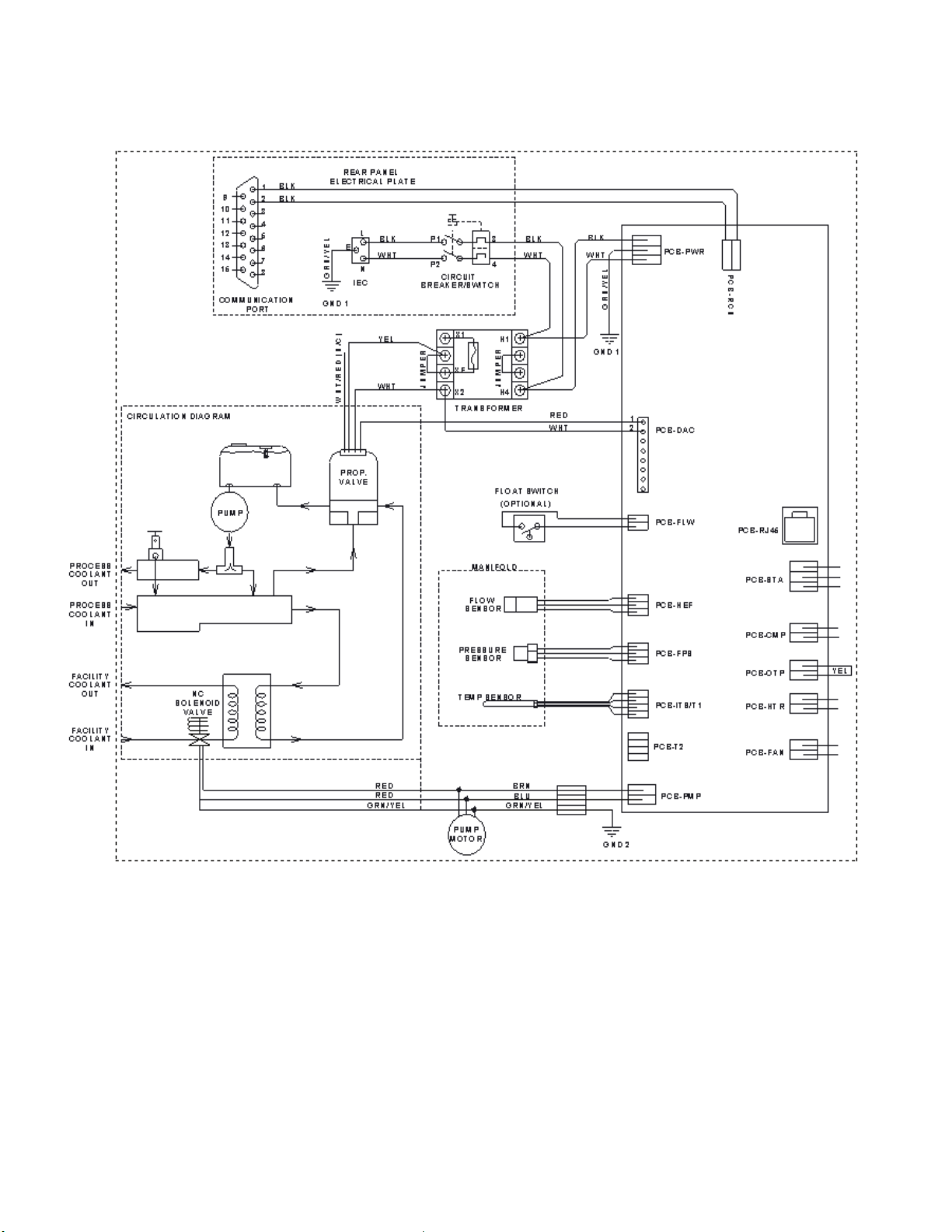
Wiring and Flow Diagram
110-497 22
Find Quality Products Online at: sales@GlobalTestSupply.com
www.GlobalTestSupply.com
Page 24
Reservoir Fluids
WWAARRNNIINNGG:: DDoo nnoott ooppeerraattee uunniitt wwiitthh aannyy ppootteennttiiaallllyy ffllaammmmaabbllee mmaatteerriiaallss,, aass aa ffiirree hhaazzaarrdd mmaayy
rreessuulltt.
.
Specific Heat
Temperature
Temperature
Temperature
BTU/lb°F
Distilled water
Ethylene glycol
(5
O)
Ethylene glycol
(30/70 mix with distilled H2O)
Propylene glycol
(50/50 mix with distilled H2O)
Propylene glycol
(30/70 mix with distilled H2O)
WARNING:
•
•
•
•
•
•
•
•
•
•
**
ives or mineral deposits may develop. If deposits are allowed to build up,
deposit build up.
Fluid Description
@ Fluid
KJ/Kg°C
Normal
Range
Extreme
Range
50°C 1.00
0/50 mix with distilled H
Automotive antifreeze with additives**
Hard tap water**
Deionized water with a specific resistance > 1 meg ohm
Any flammable fluids
Concentrations of acids or bases
Solutions with halides: chlorides, fluorides, bromides, iodides or sulfur
Bleach (Sodium Hypochlorite)
Solutions with chromates or ch romiu m salt s
Glycerine
Syltherm fluids
At temperatures above 40°C, addit
the unit may overheat and fail. Higher temperatures and higher concentrations of additives will hasten
2
-20°C 0.78
0°C 0.89
-10°C 0.83
5°C 0.92
DO NOT USE THE FOLLOWING LIQUIDS
4.18 10° to 90°C
3.26 -25° to 100°C
3.72 0° to 95°C -15° to 107°C
3.47 -20° to 100°C
3.85 5° to 90°C -10° to 107°C
2° to 100°C
-30° to 115°C
-30° to 115°C
Find Quality Products Online at: sales@GlobalTestSupply.com
110-497 23
www.GlobalTestSupply.com
Page 25

Replacement Parts
Description
Part Number
Operator’s Manual
110-497
0.33 HP Turbine Pump, bronze
215-305
0.75 HP Turbine Pump, bronze
215-499
Circuit Breaker, 15 amp
215-330
Line cord, IEC-320-19 female/NEMA 6-15P
225-230
Fluid Filter
565-102
Tank Assembly, stainless steel (no insulation)
540-504
Reservoir Low Liquid Level Switch
525-550
Bypass Valve
750-175
3-way Proportional Valve
775-513
Heat Exchanger
Circulating Bath Fluids
Quantity
Part Number
polyclean
polyclean
Twelve 8 oz / 236 ml bottles
polycool EG
polycool PG
polycool
O plus
polyclean
750-193
PolyScience Fluids
CLARIFIER 8 oz / 236 ml 004-300040
CLARIFIER
-25 (ethylene glycol) 1 gal / 4.5 liter 060340
-20 (propylene glycol) 1 gal / 4.5 liter 060320
MIX -25 (50/50 blend polycool EG -25 / H
CLARIFIER)
004-300041
2
0.5 gal / 2.27 liter bottles
Five
004-300060
110-497 24
Find Quality Products Online at: sales@GlobalTestSupply.com
www.GlobalTestSupply.com
Page 26

Optional Serial Output (RS-232)
Command
Format
Set command echo ON
SE1[CR]
1
![CR]
Set command echo OFF
SE0[CR]
0
![CR]
Turn unit ON
SO1[CR]
1
![CR]
Turn unit OFF
SO0[CR]
0
![CR]
Set set point
SSxxx[CR]
5-50°C (41° to 122°F)
![CR]
Read set point temperature
RS[CR]
----
xx.x[CR]
Read temperature
RT[CR]
----
xx.x[CR]
Read temperature units
RU[CR]
C or F
C[CR] or F[CR]
Read status
RW[CR]
1 = Run
0 = Standby
1[CR] or 0[CR]
Read pump pressure in PSI
RP[CR]
----
xx.x[CR]
Read pressure in kPa
RK[CR]
----
xx.x[CR]
Read flow in GPM
RG[CR]
----
xx.x[CR]
Read flow in LPM
RL[CR]
----
xx.x[CR]
Read ambient temperature on
Control PCB
RA[CR]
---- xx.x[CR]
Read fault status (see
Alarm and Error Messages, page
14)
RF [CR]
00 = system OK
02
![CR]
Serial Connector — A 9-pin D-connector (optional) is provided on the back panel of the Liquid-to-Liquid Cooler for
RS-232 data communication. A serial cable that uses only the following pins should be used to connect the unit to
the computer:
Pin #2 — data read (data from computer)
Pin #3 — data transmit (data to computer)
Pin #5 — signal ground
RS-232 Protocol — The controller uses the following RS-232 protocol:
Data bits — 8
Parity — none
Stop bits — 1
Flow control — none
Baud rate — selectable (Liquid-to-Liquid Cooler and PC baud rates must match).
Communications Commands — Commands must be entered in the exact format shown. Do not send a [LF] (line
feed) after the [CR] (carriage return). Be sure to follow character case exactly. A response followed by an
exclamation point (!) indicates that a command was executed correctly. A question mark (?) indicates that the
Cooler could not execute the command (either because it was in an improper format or the values were outside
the allowable range). A response must be received from the Liquid-to-Liquid Cooler before another command can
be sent. All responses are terminated with a single [CR].
Command Description
Display,
Values Return Message
-16 = Fault
110-497 25
Find Quality Products Online at: sales@GlobalTestSupply.com
www.GlobalTestSupply.com
Page 27

Equipment Disposal (WEEE Directive)
or
This equipment is marked with the crossed out wheeled bin symbol to indicate it is covered by the Waste
Electrical and Electronic Equipment (WEEE) Directive and is not to be disposed of as unsorted municipal waste.
Any products marked with this symbol must be collected separately, according to the regulatory
guidelines in your area.
It is your responsibility to correctly dispose of this equipment at lifecycle-end by handing it over to an authorized
facility for separate collection and recycling. It is also your responsibility to decontaminate the equipment in case
of biological, chemical and/or radiological contamination, so as to protect the persons involved in the disposal and
recycling of the equipment from health hazards. By doing so, you will help to conserve natural and environmental
resources and you will ensure that your equipment is recycled in a manner that protects human health.
Requirements for waste collection, reuse, recycling, and recovery programs vary by regulatory authority at your
location. Contact your local responsible body (e.g., your laboratory manager) or authorized representative for
information regarding applicable disposal regulations.
Service and Technical Support
If you have followed the troubleshooting steps and your Liquid-to-Liquid Cooler fails to operate properly, contact
the supplier from whom the unit was purchased. Have the following information available for the customer service
person:
• Model, Serial Number, and Voltage (from back panel)
• Date of purchase and your purchase order number
• Suppliers' order number or invoice number
• A summary of your problem
110-497 26
Find Quality Products Online at: sales@GlobalTestSupply.com
www.GlobalTestSupply.com
Page 28

Warranty
The manufacturer agrees to correct for the original user of the product, either by repair (using new or refurbished
parts), or at the manufacturer’s election, by replacement (with a new or refurbished product), any defects in
material or workmanship which develop during the warranty period. The standard warranty is twenty-four (24)
months after delivery of the product. In the event of replacement, the replacement unit will be warranted for the
remainder of the original warranty period or ninety (90) days, whichever is longer. For purposes of this limited
warranty, “refurbished” means a product or part that has been returned to its original specifications. In the event of
a defect, these are your exclusive remedies.
If the product should require service, contact the manufacturer’s/supplier’s office for instructions. When return of
the product is necessary, a return authorization number is assigned and the product should be shipped,
transportation charges pre-paid, in either its original packaging or packaging affording an equal degree of
protection to the indicated service center. To insure prompt handling, the return authorization number must be
placed on the outside of the package. A detailed explanation of the defect should be enclosed with the item.
The warranty shall not apply if the defect or malfunction was caused by accident, neglect, unreasonable use,
improper service, acts of God, modification by any party other than the manufacturer, or other causes not arising
out of defects in material or workmanship.
EXCLUSION OF IMPLIED WARRANTIES. THERE ARE NO WARRANTIES, EXPRESSED OR IMPLIED,
INCLUDING, BUT NOT LIMITED TO, THOSE OF MERCHANTABILITY OR FITNESS FOR A PARTICULAR
PURPOSE WHICH EXTEND BEYOND THE DESCRIPTION AND PERIOD AS STATED IN THE OPERATOR’S
MANUAL INCLUDED WITH EACH PRODUCT.
LIMITATION ON DAMAGES. THE MANUFACTURER’S SOLE OBLIGATION UNDER THE WARRANTY IS
LIMITED TO THE REPAIR OR REPLACEMENT OF A DEFECTIVE PRODUCT AND THE MANUFACTURER
SHALL NOT, IN ANY EVENT, BE LIABLE FOR ANY INCIDENTAL OR CONSEQUENTIAL DAMAGES OF ANY
KIND RESULTING FROM USE OR POSSESSION OF THIS PRODUCT.
Some states do not allow: (A) limitations on how long an implied warranty lasts; or (B) the exclusion or limitation
of incidental or consequential damages, so the above limitations or exclusions may not apply to you. This
warranty gives you specific legal rights and you may have other rights that vary from state to state.
110-497 27
Find Quality Products Online at: sales@GlobalTestSupply.com
www.GlobalTestSupply.com
 Loading...