


Operator’s Manual
Liquid-to-Air Recirculator
Original Instructions
110-368 09.02.15
Find Quality Products Online at: sales@GlobalTestSupply.com
www.GlobalTestSupply.com

Table of Contents
Introduction .............................................................................................................................................................. 2
General Information ................................................................................................................................................. 2
General Safety Information .................................................................................................................................... 2
Safety Recommendations ...................................................................................................................................... 3
Regulatory Compliance and Testing ...................................................................................................................... 3
Unpacking Your Recirculator ................................................................................................................................. 3
Contents ................................................................................................................................................................. 3
Controls and Components ..................................................................................................................................... 4
Installation and Startup ........................................................................................................................................... 5
Site Requirements ................................................................................................................................................. 5
Ambient Temperature and Relative Humidity .................................................................................................... 5
Location .............................................................................................................................................................. 5
Clearance ........................................................................................................................................................... 5
Electrical Power ..................................................................................................................................................... 5
Plumbing ................................................................................................................................................................ 6
Process Piping ................................................................................................................................................... 6
Reservoir Drain .................................................................................................................................................. 6
Startup .................................................................................................................................................................... 6
Process Coolant ................................................................................................................................................. 6
Electrical Power .................................................................................................................................................. 7
Starting Process Fluid Flow ................................................................................................................................ 7
Safety By-Pass Pressure Regulator Adjustment ................................................................................................... 7
Positive Displacement Pump .............................................................................................................................. 7
Turbine Pump ..................................................................................................................................................... 8
Normal Operation .............................................................................................................. ...................................... 9
Routine Maintenance & Troubleshooting ............................................................................................................. 9
Draining Reservoir (Preparing for Transportation or Storage) ............................................................................... 9
Periodic Inspection ................................................................................................................................................. 9
Cleaning Exterior Surfaces .................................................................................................................................... 9
Condenser, Air Vents and Reusable Filter .......................................................................................................... 10
Fluid Filter ............................................................................................................................................................ 10
Fluid Level ............................................................................................................................................................ 10
Troubleshooting ................................................................................................................................................... 10
Technical Information ........................................................................................................................................... 11
Performance Specifications ................................................................................................................................. 11
Replacement Parts ................................................................................................................................................ 12
Wiring Diagram ...................................................................................................................................................... 12
Equipment Disposal (WEEE Directive) ................................................................................................................ 13
Service and Technical Support ............................................................................................................................ 13
Warranty ................................................................................................................................................................. 14
110-368 1
Find Quality Products Online at: sales@GlobalTestSupply.com
www.GlobalTestSupply.com

Introduction
This Liquid-to-Air Recirculator continuously pumps near-ambient temperature water from a reservoir to an
external heat source, through a cooling radiator, and then returns cooled water to the reservoir. By blowing
ambient air over the radiator, water flowing inside is cooled and the heat is exhausted into the atmosphere.
General Information
General Safety Information
When installed, operated, and maintained according to the directions in this manual and common safety
procedures, your Recirculator should provide safe and reliable heat removal. Please ensure that all individuals
involved in the installation, operation, or maintenance of this unit read this manual thoroughly prior to working with
the unit.
This symbol alerts you to a wide range of potential dangers.
This symbol advises you of danger from electricity or electric shock.
This symbol marks information that is particularly important.
This symbol indicates alternating current.
/
These symbols on the Power Switch / Circuit Breaker indicate that they place the main power supply ON / OFF.
This symbol on the Power Switch indicates that it places the unit in a standby mode. It DOES NOT fully
disconnect the unit from the power supply.
This symbol indicates a protective conductor terminal.
Read all instructions pertaining to safety, set-up, and operation.
Proper operation and maintenance is the user’s responsibility.
Protection can be impaired if the equipment is used in a manner not specified by the
manufacturer.
110-368 2
Find Quality Products Online at: sales@GlobalTestSupply.com
www.GlobalTestSupply.com

Safety Recommendations
To prevent injury to personnel and/or damage to property, always follow your workplace’s safety procedures when
operating this equipment. You should also comply with the following safety recommendations :
WARNING:
Always connect the power cord on this unit to a grounded (3-prong) power outlet. Make
certain that the outlet is the same voltage and frequency as your unit.
Never operate the unit with a damaged power cord.
Always turn the unit OFF and disconnect Mains power before performing any maintenance
or service.
Regulatory Compliance and Testing
Canada USA (60Hz units)
CAN/CSA C22.2 No. 61010-1-12 — Safety Requirements for Electrical Equipment for Measurement, Control
and Laboratory Use, Part I: General Requirements
UL Std. No. 61010-1 (2012) — Electrical Equipment for Laboratory Use, Part I: General Requirements
CE (50 Hz units)
Machinery Directive 2006/42/EC
EC Electromagnetic Compatibility Directive 2014/30/EU
RoHS Directive 2011/65/EU
IEC 61010-1 / EN 61010-1:2010
Highly Accelerated Life Test (HALT) and Vibration Tests per ASTM D4169-8 (all units)
A-Weighted Emission Sound Pressure Level: Does not exceed 70 db(A)
Unpacking Your Recirculator
Your Recirculator is shipped in a special carton. Retain the carton and all packing materials until the unit is
completely assembled and working properly. Set up and run the unit immediately to confirm proper operation.
Beyond one week, your unit may be warranty repaired, but not replaced. If the unit is damaged or does not
operate properly, contact the transportation company, file a damage claim and immediately contact the company
where your unit was purchased.
WARNING: Keep unit upright when moving. Be sure to follow your company’s procedures and practices
regarding the safe lifting and relocation of heav y object s. For items weighing 18kg or more, safe practice lifting
should be performed by at least two people.
Contents
The following items have been included with your Recirculator:
Operator’s Manual
IEC Power Cord
Two sets of nylon Inlet/Outlet adapters:
½ inch male NPT to ½ inch barb 90° elbow
½ inch male NPT to 5/8 inch barb 90° elbow
110-368 3
Find Quality Products Online at: sales@GlobalTestSupply.com
www.GlobalTestSupply.com
r
/
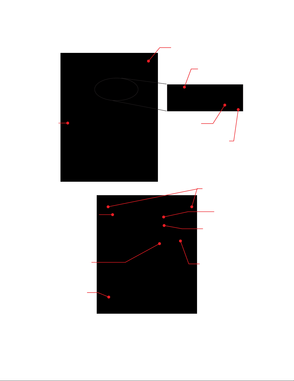
Controls and Components
Reservoir Cap
Pressure Gauge
Air Filter Access
Reservoir Liquid
Level Indicator
Fluid Inlet
Low Liquid Level
Warning Indicato
Power Switch
Top Panel Access Screws
Circuit Breaker
Power Switch
IEC Power Inlet
Fluid Outlet
Drain
110-368 4
Find Quality Products Online at: sales@GlobalTestSupply.com
www.GlobalTestSupply.com

Installation and Startup
WARNING: Be sure all power is off before proceeding.
Site Requirements
Ambient Temperature and Relative Humidity
The Recirculator is designed for indoor installation in ambient temperatures between 5° and 35°C (41° and 95°F);
relative humidity should not exceed 80% (non-condensing).
Location
The Recirculator should be installed on a strong, level surface. It should be located as close to possible to the
process requiring cooling. It should not be installed closer than 4 feet (1.2 meters) to a heat-generating source,
such as heating pipes, boilers, etc. If possible, the Recirculator should be located near a suitable drain to prevent
flooding in the event of leaks. Do not place it where corrosive fumes, excessive moisture, excessive dust, or high
room temperatures are present.
For ease of positioning and maneuverability, the Recirculator is supplied with ca sters. The front wheels can be
locked to keep the Recirculator in place while in use.
To help prevent voltage drops, position the Recirculator as close as possible to the power distribution panel.
Avoid voltage drops by using a properly grounded power outlet wired with 14 gauge or larger diameter wire. The
use of an extension cord is not recommended.
CAUTION: The Recirculator may be located at a level below that of the equipm ent being cooled. As long as
the process remains closed, overflow will not occur when adding coolin g fluid to the Recirculator reservoir.
Clearance
Adequate clearance should be allowed on the front, sides, and rear of the Recirculator for access to connections
and components. The front and rear vents of the Recirculator must be a minimum of 24 inches (61 cm) away from
walls or vertical surfaces so air flow is not restricted.
Electrical Power
An IEC power cord is provided with the Recirculator. It should be attached to the receptacle on the rear of the
enclosure. Make sure that the power outlet used for the Recirculator is properly grounded and matches the
voltage and frequency indicated on the identification label on the back of the Recirculator.
The use of an extension cord is not recommended. However, if one is necessary, it must be properly grounded
and capable of handling the total wattage of the unit. The extension cord must not cause more than a 10% drop in
voltage to the Recirculator.
WARNING: DO NOT plug the Recirculator into the electrical outlet until the unit is ready for startup (see
Startup).
110-368 5
Find Quality Products Online at: sales@GlobalTestSupply.com
www.GlobalTestSupply.com

Plumbing
Process Piping
The Recirculator has two internally threaded (1/2 inch NPT) fittings on the rear
of the instrument housing for the process water connections. The outlet of the
heat source should be connected to the inlet of the Recirculator and the inlet of
the heat source connected to the outlet of the Recirculator. Use heavy wall
tubing, preferably reinforced, to make the connections. Minimize bends in the
tubing as well as the length of tubing from the Recirculator to the heat source.
Do not run the connecting tubing near any type of heat source. Be sure all connections are secure and clamped
before filling with water.
Reservoir Drain
A ½ inch NPT connection is provided for the reservoir’s gravity drain. It should be piped to a drain or receptacle
positioned below the bottom of the reservoir. If a receptacle is used, be sure it is of sufficient volume to hold all
the water in the reservoir, process, and process lines.
Startup
Process Coolant
Distilled water is recommended. To prevent algae growth in the system, shield tubing from light. Insulation around
the tubing will suffice. Use an algaecide (such as polyclean CLARIFIER, 004-300040) in the cooling water to
minimize algae growth.
Wetted components of this Recirculator are copper, brass, PVC, polyethylene, nylon, and stainless steel. Any
fluids used in the circulating system must be compatible with these materials.
WARNING: Do NOT use chlorine bleach as an algaecide.
WARNING: Do not use the following fluids:
Automotive antifreeze with additives
Hard tap water
Deionized water with a specific resistance > 1 meg ohm (except units with DI water compatible
plumbing)
Any flammable fluids
Concentrations of acids or bases
Solutions with halides: chlorides, fluorides, bromides, iodides or sulfur
Bleach (Sodium Hypochlorite)
Solutions with chromates or chromium salts
Glycerin
Syltherm fluids
WARNING: Do not use a flammable liquid as a fire hazard may result.
Filling the Reservoir
Remove the filler cap from the reservoir and, using a funnel, add fluid until it reaches the MAX line on the
reservoir’s fluid level gauge. Once the reservoir is full, remove the funnel but do not replace the cap at this time.
110-368 6
Find Quality Products Online at: sales@GlobalTestSupply.com
www.GlobalTestSupply.com

Electrical Power
Plug the Recirculator’s power cord into an appropriate electrical outlet.
Place the Circuit Breaker/Power Switch on the rear of the instrument enclosure in the ON position.
Starting Process Fluid Flow
Press the Power Button on the front panel. The system startup sequence will begin and proceed as follows:
1. The cooling fan and pump will turn on and fluid will begin circulating through the system.
2. With the pum p running, the reservoir’s fluid level will drop as the process and/or process cooling lines fill
with fluid. Slowly add fluid to the reservoir until the liquid level remains stable.
3. Check all plumbing connections for leaks. If leaks are found, do not continue to operate the Recirculator
until all connections are secure.
CAUTION: Never let the Recirculator pump run dry.
Safety By-Pass Pressure Regulator Adjustment
Positive Displacement Pump
Cover Nut
To protect the pump in case of blockage or shut off of fluid flow, a Safety By-Pass Relief Valve is built into the
pump head. This permits fluid to continue flowing within the pump and minimizes the possibility of damage due to
a dry pump.
Adjustment of the Safety By-Pass Pressure Relief Valve (factory set at 50 psi / 3.44 bar):
1. Attach a fluid-filled pressure gauge (not supplied) with a range of 0 to 150 psi ( 0 to 10.3 bar) to the
Recirculator outlet fitting to prevent fluid flow.
110-368 7
Find Quality Products Online at: sales@GlobalTestSupply.com
www.GlobalTestSupply.com

2. Fill the reservoir as indicated in the Startup section.
3. To access the pressure by-pass valve, remove the two screws at the upper left and right corners of the
Recirculator’s rear panel, slide the top panel back about 2-3 inches (5 to 7.6 cm) and lift off. Remove the right
side panel by lifting it straight up from the frame. The valve is located in the bottom right rear corner of the unit
(when facing the unit).
4. Turn the unit ON and check for leaks. Be sure pressure gauge is not leaking. The gauge should display
approximately 50 psi (3.44 bar).
5. Remove the Cover Nut on the pump head to access the Adjustment Screw.
6. To INCREASE the Safety By-Pass Relief pressure setting, use a flat head screwdriver to turn the Adjustment
Screw clockwise; to DECREASE the pressure setting, turn the pressure Adjustment Screw counter-clockwise.
While reading the pressure gauge, continue turning the Adjustment Screw until the desired setting is
achieved.
CAUTION: Maximum pressure is 100 psi (6.88 bar). Care must be taken to limit adjustment of Safety ByPass Relief Valve setting to 100 psi (6.88 bar) or less. Damage may occur at settings exceeding 100 psi
(6.88 bar) and will void the warranty.
Turbine Pump
To protect the pump in case of blockage or shut off of fluid flow, a Safety By-Pass Relief Valve is built into the
unit. This permits fluid to continue flowing within the pump and minimizes the possibility of damage due to a dry
pump.
Adjustment of the Safety By-Pass Relief Valve (factory set at 50 psi / 3.44 bar):
1. Attach a fluid-filled pressure gauge (not supplied) with a range of 0 to 150 psi ( 0
to 10.3 bar) to the Recirculator outlet fitting to prevent fluid flow.
2. Fill the reservoir as indicated in the Startup section.
3. To access the pressure by-pass valve, remove the two screws at the upper left
and right corners of the Recirculator’s rear panel, slide the top panel back about
2-3 inches (5 to 7.6 cm) and lift off. The valve is located in the top left rear corner
of the unit (when facing the unit).
4. Turn the unit ON and check for leaks. Be sure pressure gauge is not leaking.
The gauge should display approximately 50 psi (3.44 bar).
Cover lock nut
5. Loosen the Cover Lock Nut on the by-pass valve.
6. To INCREASE the Safety By-Pass Relief pressure setting, turn the Adjustment Handle clockwise; to
DECREASE the pressure setting, turn the pressure Adjustment Handle counter-clockwise. While reading the
pressure gauge, continue turning the Adjustment Handle until the desired setting is achieved.
7. Tighten the Cover Lock Nut.
CAUTION: Maximum pressure is 100 psi (6.88 bar). Care must be taken to limit adjustment of Safety ByPass Relief Valve setting to 100 psi (6.88 bar) or less. Damage may occur at settings exceeding 100 psi
(6.88 bar) and will void the warranty.
110-368 8
Find Quality Products Online at: sales@GlobalTestSupply.com
www.GlobalTestSupply.com

Normal Operation
NOTE: Recirculating Coolers operate at maximum cooling performance. Actual coolin g
performance will vary based on ambient temperature.
1. Place the Power Switch / Circuit Breaker on the rear of the Recirculator in the ON position.
2. Press the Power Switch on the front panel. The cooling fan and pump will begin running and fluid will
begin circulating through the system. The pressure gauge on the front of the unit indicates fluid pressure
at the outlet of the Recirculator.
Routine Maintenance & Troubleshooting
WARNING: Refer servicing to qualified service personnel.
WARNING: When electrical power is ON, dangerous voltages exist within chassis com ponents. Use extreme
care when measuring voltages on live circuits.
Draining Reservoir (Preparing for Transportation or Storage)
Due to potential exposure to freezing temperatures, the following
procedure is recommended for use when transporting or storing the unit.
Follow this procedure to evacuate fluid from the Heat Exchanger Coil and
reduce the potential for damage to coil copper lines.
Reservoir fluids should be piped to a drain or receptacle positioned below
the bottom of the reservoir. If a receptacle is used, be sure it is of
sufficient volume to hold all the water in the reservoir, process, and
process lines. Removing the drain plug will allow fluid to exit the unit. Make sure to replace the plug when done.
Factory-installed
Drain
drain plug
Periodic Inspection
All components should be inspected at least once a month or more frequently if the Recirculator is used
continuously. Examine all fittings for leaks and also check the fluid level. If the level is low, check the heat source
as well as the Recirculator for leaks. Replace the recirculating fluid every three months. If algae growth is noted,
replace more frequently.
Cleaning Exterior Surfaces
Only mild detergents and water or an approved cleaner should be used on the painted surfaces of your
Recirculator.
110-368 9
Find Quality Products Online at: sales@GlobalTestSupply.com
www.GlobalTestSupply.com

Condenser, Air Vents and Reusable Filter
To keep the system operating at optimum cooling capacity, the condenser, the air vents, and
reusable filter should be kept free of dust and dirt. They should be checked on a regular basis
and cleaned as required.
The reusable filter is easily accessed from either the left or right side of the unit. Use a mild
detergent and water solution to wash off any accumulated dust and dirt. Rinse and dry
thoroughly before reinstalling.
Fluid Filter
A removable, highly efficient fluid filter is integrated into the fluid reservoir. To remove it for cleaning, simply
remove the reservoir cap and lift the filter out of the reservoir. Rinse off accumulated particulate matter and
reinstall.
Fluid Level
The fluid level gauge on the rear of the Recirculator should be periodically checked to determine if the fluid level
needs to be topped off. Generally, fluid should be added whenever the level in the reservoir is at or near the “Low”
gauge mark.
Troubleshooting
WARNING: Always turn the Power Switch / Circuit Breaker OFF and disconnect the electrical cord from the
power source before servicing the unit.
Problem Cause Corrective Action
Unit does not run
No cooling or
insufficient cooling
No power to unit
Rear Power Switch / Circuit
Breaker in OFF position
Front Power Switch OFF
No power to unit
Blocked airflow
Ambient air temperature too
high
Fluid too hot for unit to
continuously cool
Heat exchanger fan not
operating
Check that electrical cord is plugged into an operating
electrical outlet.
Place Power Switch / Circuit Breaker in ON position.
Place Power Switch in ON position.
Check that rear Power Switch / Circuit Breaker and/or
front Power Switch is ON.
Check heat exchanger fins and air vents for blockages.
Check ambient air temperature.
Check heat removal specifications; heat loss to room may
be excessive.
Check fan for operation (listen for fan noise, check for
airflow through unit).
110-368 10
Find Quality Products Online at: sales@GlobalTestSupply.com
www.GlobalTestSupply.com

Technical Information
Performance Specifications
Positive Displacement Pump
Turbine Pump
500 watts based on 2°C ǻT
1000 watts based on 4°C ǻT
Cooling Capacity @ 20°C
2000 watts based on 8°C ǻT
3000 watts based on 10°C ǻT
4000 watts based on 11°C ǻT
Dimensions (L x W x H) 20.5 x 15 x 22.3 in. (52 x 38.1 x 56.6 cm)
External Fluid Connections Inlet & Outlet, 1/2 in. female NPT
Reservoir Capacity 1.1 gallons (4.2L)
Maximum Liquid Temperature 170°F (77°C)
Electrical Requirements
Maximum Fluid Flow Rate
By-Pass Pressure Regulator
Shipping Weight 118 Lbs (53.5 kg) 132 Lbs (59.9 kg)
Recommended Coolant Distilled Water
ǻT = Process water temperature – ambient air temperature
Environmental Conditions Indoor use only
Maximum Altitude: 2000 meters
Operating Ambient: 5° to 35°C (41° to 95°F
Relative Humidity: 80% for temperatures to 30°C
Installation Category II
Pollution Degree: 2
120VAC, 60Hz,
1 ph, 7A
2.4 gpm (9.1 lpm) 2 gpm (7.6 lpm)
240VAC, 50Hz,
1 ph, 3.75A
Adjustable 20 to 100 psi / 1.4 to 6.9 bar
(Factory pre-set to 50 psi / 3.44 bar)
120VAC, 60Hz,
1 ph, 7A
5.4 gpm
(15.2 lpm)
240VAC, 50-60Hz,
4.5 gpm (17.1 lpm)
1 ph, 4.75A
110-368 11
Find Quality Products Online at: sales@GlobalTestSupply.com
www.GlobalTestSupply.com

Replacement Parts
Description Part Number
Positive Displacement Pump Motor 215-217
Pump Head (2.3 gpm) 215-218
Turbine Pump T31E-4GPM 215-328
Air Filter, Reusable 750-855
Reservoir Cap 300-460
Reservoir Strainer 565-102
Fan Motor, 35W, 120VAC 525-306
Fan Motor, 35W, 240VAC 525-311
Fan Blade (35W motor), 115VAC and 240VAC 215-076
Fan Motor, 50W, 240VAC 525-710
Fan Blade (50W motor), 240VAC 215-309
Fan Blade Collar (50W motor), 240VAC 400-533
Gauge, Pressure 750-076
polyclean CLARIFIER 004-300040
Wiring Diagram
110-368 12
Find Quality Products Online at: sales@GlobalTestSupply.com
www.GlobalTestSupply.com

Equipment Disposal (WEEE Directive)
or
This equipment is marked with the crossed out wheeled bin symbol to indicate it is covered by the Waste
Electrical and Electronic Equipment (WEEE) Directive and is not to be disposed of as unsorted municipal waste.
Any products marked with this symbol must be collected separately, according to the regulatory
guidelines in your area.
It is your responsibility to correctly dispose of this equipment at lifecycle-end by handing it over to an authorized
facility for separate collection and recycling. It is also your responsibility to decontaminate the equipment in case
of biological, chemical and/or radiological contamination, so as to protect the persons involved in the dispo sal an d
recycling of the equipment from health hazards. By doing so, you will help to conserve natural a nd environmental
resources and you will ensure that your equipment is recycled in a manner that protects human health.
Requirements for waste collection, reuse, recycling, and recovery programs vary by regulatory authority at your
location. Contact your local responsible body (e.g., your laboratory manager) or authorized representative for
information regarding applicable disposal regulations.
Service and Technical Support
If you have followed the troubleshooting steps and your Recirculator fails to operate properly, contact the supplier
from whom the unit was purchased. Have the following information available for the customer service pe rson:
Model, Serial Number, and Voltage (from back panel)
Date of purchase and your purchase order number
Suppliers' order number or invoice number
A summary of your problem
110-368 13
Find Quality Products Online at: sales@GlobalTestSupply.com
www.GlobalTestSupply.com

Warranty
The manufacturer agrees to correct for the original user of the product, either by repair (using new or refurbished
parts), or at the manufacturer’s election, by replacement (with a new or refurbished product), any defects in
material or workmanship which develop during the warranty period. The standard warranty is twenty-four (24)
months after delivery of the product. In the event of replacement, the replacement unit will be warranted for the
remainder of the original warranty period or ninety (90) days, whichever is longer. For purposes of this limited
warranty, “refurbished” means a product or part that has been returned to its original specifications. In the event of
a defect, these are your exclusive remedies.
If the product should require service, contact the manufacturer’s/supplier’s office for instructions. When return of
the product is necessary, a return authorization number is assigned and the product should be shipped,
transportation charges pre-paid, in either its original packaging or packaging affording an equal degree of
protection to the indicated service center. To insure prompt handling, the return authorization number must be
placed on the outside of the package. A detailed explanation of the defect should be enclosed with the item.
The warranty shall not apply if the defect or malfunction was caused by accident, neglect, unreasonable use,
improper service, acts of God, modification by any party other than PolyScience, or other causes not arising out of
defects in material or workmanship.
EXCLUSION OF IMPLIED WARRANTIES. THERE ARE NO WARRANTIES, EXPRESSED OR IMPLIED,
INCLUDING, BUT NOT LIMITED TO, THOSE OF MERCHANTABILITY OR FITNESS FOR A PARTICULAR
PURPOSE WHICH EXTEND BEYOND THE DESCRIPTION AND PERIOD AS STATED IN THE OPERATOR’S
MANUAL INCLUDED WITH EACH PRODUCT.
LIMITATION ON DAMAGES. THE MANUFACTURER’S SOLE OBLIGATION UNDER THE WARRANTY IS
LIMITED TO THE REPAIR OR REPLACEMENT OF A DEFECTIVE PRODUCT AND POLYSCIENCE SHALL
NOT, IN ANY EVENT, BE LIABLE FOR ANY INCIDENTAL OR CONSEQUENTIAL DAMAGES OF ANY KIND
RESULTING FROM USE OR POSSESSION OF THIS PRODUCT.
Some states do not allow: (A) limitations on how long an implied warranty lasts; or (B) the exclusion or limitation
of incidental or consequential damages, so the above limitations or exclusions may not apply to you. This
warranty gives you specific legal rights and you may have other rights that vary from state to state.
110-368 14
Find Quality Products Online at: sales@GlobalTestSupply.com
www.GlobalTestSupply.com
 Loading...