

Page 1

3032 MICROSCOPE SERIES
INSTRUCTIONS
US Headquarters
400 Valley Road
Warrington, PA 18976
(800) 523-2575 / (215) 343-6484
(800) 343-3291 / (215) 343-0214 fax
info@polysciences.com
www.polysciences.com
Our catalog lists over 3,000 unique and specialty products that are used by histology professionals, lab technicians,
pathologists, chemists and scientists worldwide. Visit www.polysciences.com to learn more about our product lines.
European Headquarters
Handelsstrasse 3
D-69214 Eppelheim
Germany
(49) 6221-765767
(49) 6221-764620 fax
info@polysciences.de
Asia-Pacific Headquarters
Polysciences Asia Pacific, Inc.
2F-1, 207 DunHua N. Rd.
Taipei, Taiwan 10595
(886) 2 8712 0600
(886) 2 8712 2677 fax
info@polysciences.tw
Page 2
3032
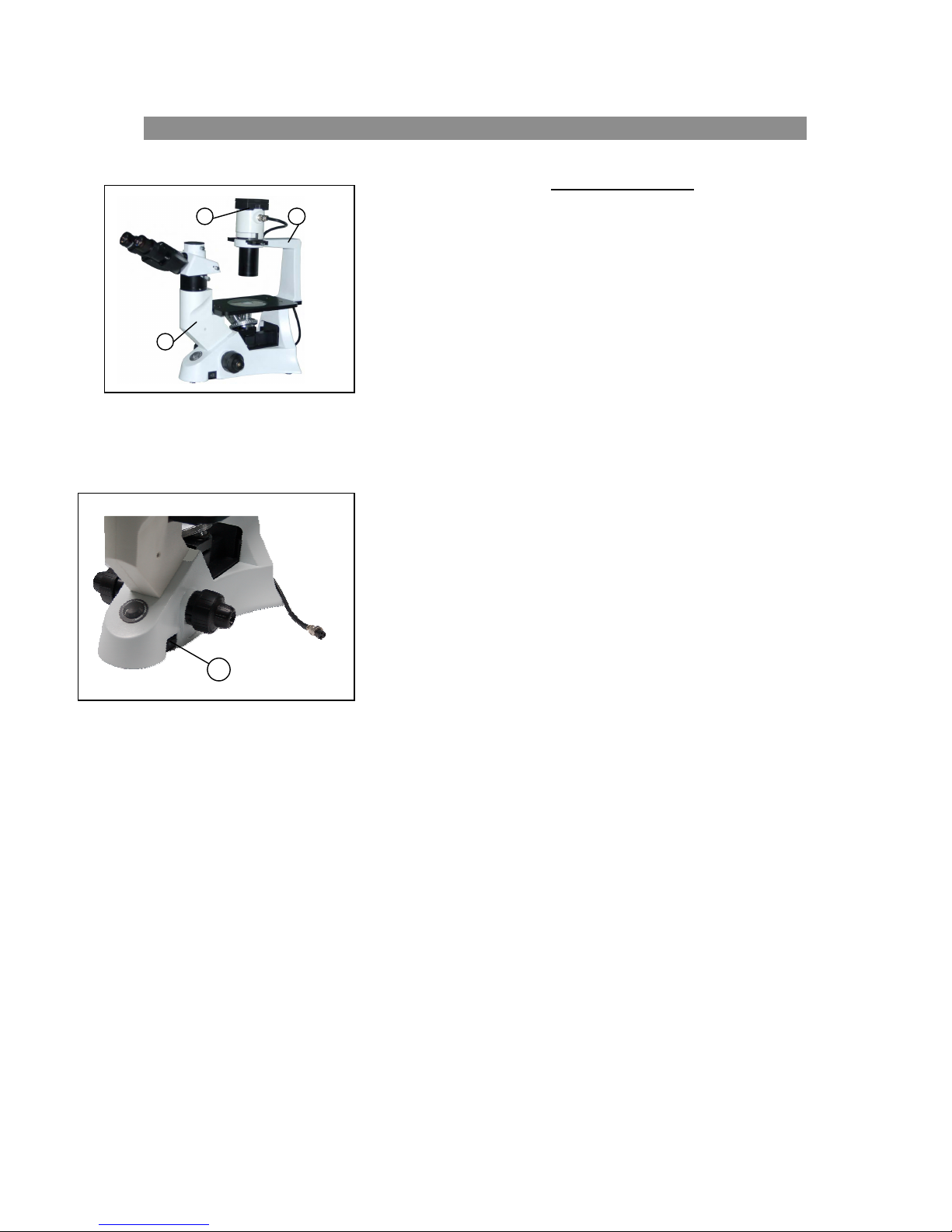
SAFETY NOTES
. Ope
3
2
1
Figure 1
1
2. Do not discard the molded Styrofoam container; the container
3. Keep the instrument out of direct sunlight, high temperature or
4. If any specimen solutions or other liquids splash onto the stage,
5. CAUTION: The lamp, lamp house (Fig.1-3) and adjacent parts
the shipping carton carefully to prevent any accessory, i.e.
n
objectives or eyepieces, from dropping and being damaged.
should be retained should the microscope ever require
reshipment.
humidity or dusty environments. Ensure the microscope is
located on a smooth, level and firm surface.
objective or any other component, disconnect the power cord
immediately and wipe up the spillage. Otherwise, the instrument
may be damaged.
will become very hot. Do not touch these parts until they have
completely cooled. Never attempt to handle a hot halogen bulb.
6. All electrical connectors (power cord) should be inserted into an
4
Figure
2
electrical surge suppressor to prevent damage due to voltage
fluctuations.
7. For safety when replacing the halogen lamp or fuse, ensure the
main switch is off (“O”), remove the power cord, and replace the
halogen bulb after the bulb and the lamp house has completely
cooled.
8. Confirm that the input voltage indicated on your microscope
corresponds to your line voltage. The use of a different input
voltage than indicated will cause severe damage to the
microscope.
9. When moving the microscope, hold the instrument with one
hand on the lower portion of the eyepiece tube (Fig. 1-1) and the
other hand on the illumination bracket (Fig. 1-2)
10. Halogen lamp: 6 volt 30 watts. Do not use a lamp with
different specifications.
Page 3

CARE A
. Do no
1
2. Keep the instrument clean; remove dirt and debris regularly. Accumulated dirt on metal
3. The outer surface of the optics should be inspected and cleaned periodically using an air
t attempt to disassemble any component including eyepieces, objectives or focusing
assembly.
surfaces should be cleaned with a damp cloth. More persistent dirt should be removed using
a mild soap solution. Do not use organic solvents for cleansing.
stream from an air bulb. If dirt remains on the optical surface, use a soft cloth or cotton
swab dampened with a lens cleaning solution (available at camera stores). All optical lenses
should be swabbed using a circular motion. A small amount of absorbent cotton wound on
the end of a tapered stick makes a useful tool for cleaning recessed optical surfaces. Avoid
using an excessive amount of solvents as this may cause problems with optical coatings or
cemented optics or the flowing solvent may pick up grease making cleaning more difficult.
Oil immersion objectives should be cleaned immediately after use by removing the oil with
lens tissue or a clean, soft cloth.
ND MAINTENANCE
4. Store the instrument in a cool, dry environment. Cover the microscope with the dust cover
when not in use.
5. Microscopes are precision instruments which require periodic servicing to maintain
prope
r performance and to compensate for normal wear. A regular schedule of
preventative maintenance by qualified personnel is highly recommended. Your authorized
distributor can arrange for this service.
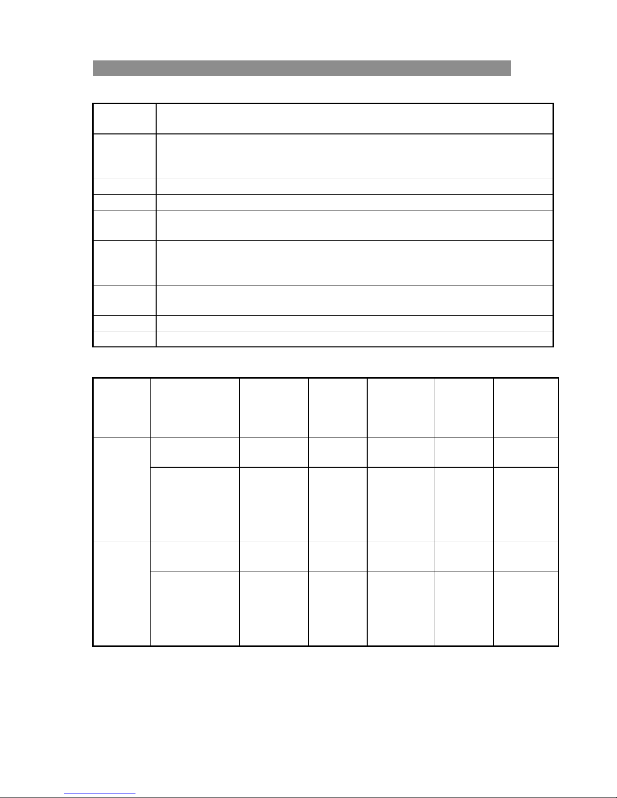
SAFETY SYMBOLS
Symbol Meaning
The su
Before
rface is very hot. Do not touch with your hands.
using, please read the instructions carefully. Improper operation may
result in injury or microscope malfunction.
The ma
The ma
in switch is “on”
in switch is “off”
Page 4
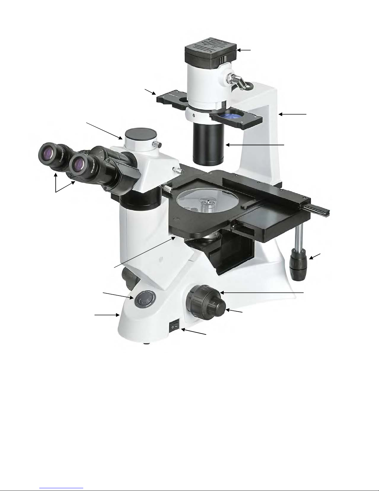
Phase Annuli Slider
Trinocular Viewing
Head
Lamp House
Illum
Bracket
ination
Eyepieces
Stage
Variable Light Intensity
Adjus
tment Dial
Base
Conden
Fine Focus Knob
ser
X & Y
Stage
ovement
M
Controls
Coarse Focus
Knob
3032 INVERTED MICROSCOPE SERIES
On/Off Switch
1
Page 5
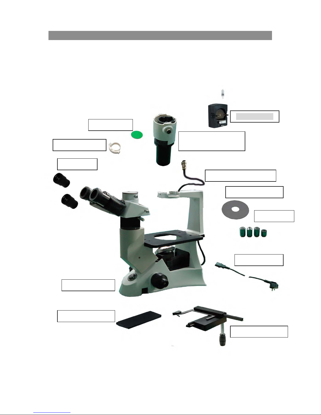
2....Assembly
2.1 Assembly Diagram
The following figure shows the correct installation seque
components in the exact numerical sequence as in the diagram.
Inspect all optical surfaces for dust and debris; clean if necessary.
Please save the hexagonal wrench for future use.
Retain all stryofoam cartons if reshipment is ever required.
nce of the components. Assemble the
3032
Filter Holder ((10)
Eyepieces (8)
Color Filter (9)
Lamp House (3)
Condenser Illumination
bly (1)
Assem
BNC Electrical Cable (2)
Glass Stage Plate (7)
Objectives (4)
Power Cord (11)
Microscope Base
Stage Extension (6)
Mechanical Stage (5)
Figure 2
2
Page 6
1
3
5
6
4
2
3032
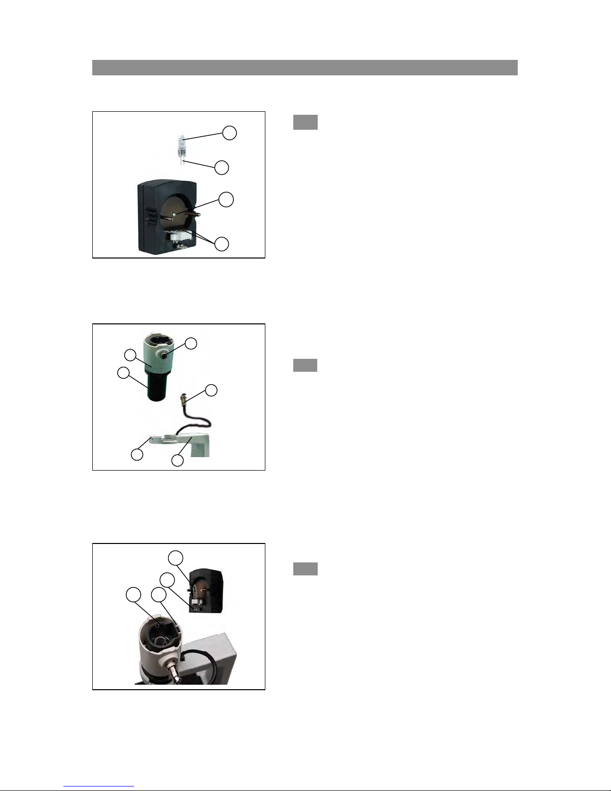
2.2 Assembly Steps
2-2-1 Installing and Replacing the Lamp (Figure 3)
se the specified halogen lamp: 6V30W
U
4
Wrap the bulb (1) with gauze or lint free paper; press the
pins (2) into the socket (3) in the lamp house.
Figure 3
When replacing the lamp turn the main switch to “O” (off)
and remove the power cord. Allow the lamp, lamp house
and the adjacent areas to sufficiently cool before handling.
The lamp will become very hot and will cause burns.
Do n
Fingerprints on the bulb may shorten the bulb life or
interfere with the illumination. Clean all fingerprints
with a dry soft cloth.
ot touch the halogen bulb with your hands.
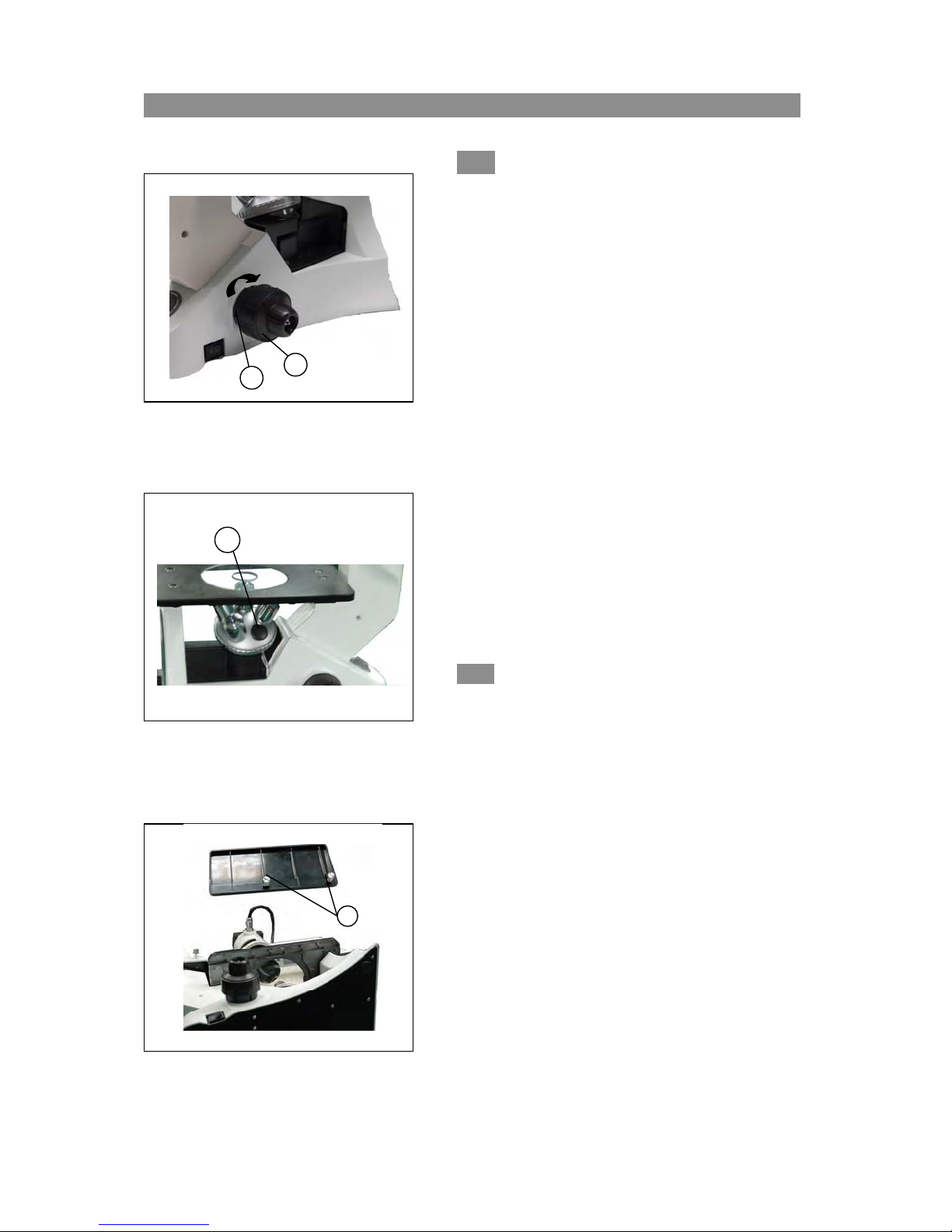
2-2-2 Installing the Condenser Illumination
Assem
bly((((Figure 4))))
Figure 4
4
3
2
1
1. Insert the condenser illumination unit (1) into the
bracket (2).
2. Turn the condenser illumination unit at clockwise
about 90 until the “AS” mark of filter holder③ is
facing forward.
3. Keep the screws the of condenser illumination
unit and the holes of the bracket aligned. Tighten the
screws with the supplied hexagon wrench.
4. Insert BNC connector cable ④ into the BNC
connector plug ⑤.
2-2-3 Installing the Lamp House (Figure 5)
the BNC connector plug① and the lamp house
Keep
pin② aligned. Also keep the bolt③ and the condenser
jack④ aligned. Then gently push the lamp house into
the illumination unit until they are completely
connected.
Figure 5
)
)
)
3
Page 7
1
2
Figure 6
3
Figure 7
1
2-2-4 Installing the Objectives(
1. Turn the coarse focusing knob① clockwise until the
nosepiece reaches its lowest position. The tension
control collar (2) has been factory adjusted.
2. Install the lowest magnification objective into the
nosepiece. Then, in a clock-wise direction, rotate the
nosepiece and install each succeeding higher
magnification objective.
3. When changing objective magnifications, rotate the
nosepiece until you hear a “click” sound. This ensures
the objective is centered in the optical light path.
★ Inspect the objectives regularly for dirt and oil; clean
necessary.
★ Cover all unused nosepiece holes with a nosepiece
plug③ to prevent dust and contamination from entering.
★ Use the 10x objective to initially focus the image of your
imen.
spec
2-2-5
Extension
1. Attach the mechanical stage to the right side of the fixed
2. Attach the stage extension to the left side of the fixed
Attaching the Mechanical Stage and Stage
((((
Figure 8
stage by tightening the two thumb screws on the
underside of the mechanical stage.
stage by tightening the two thumb screws (1) on the
underside of the stage extension.
Figure 8
4
3032
))))
(Fig
(
(
6 & 7))))
.
if
Page 8

1
2-2-6 Installing the Stage Plate(
1. Install the glass stage plate ① into the stage opening.
Figure 9
1
2-2-7 Installing the Eyepieces((((Figu
1. Remove the protective caps on the eyepiece tubes①.
3032
(Fig
(
(
re 9))))
u
re 10))))
2
Figure 10
2. I
nsert completely the eyepieces into eyetubes.
2-2-8 Installing the Color Filters (Figure 11)
★ Allow the color filter to cool completely before you
e them. Remove the filter holder①, and then
chang
insert the color filter ②required.
2
● Mount the color filter so it lays flat ③ in the holder as
shown.
★ The color filter must be laying flat. If not, the filter
1
3
Figure 11
has b
een installed incorrectly④④④④.
● More than one filter may be installed only if the total
thickness is less than 11mm.
5
Page 9
3032
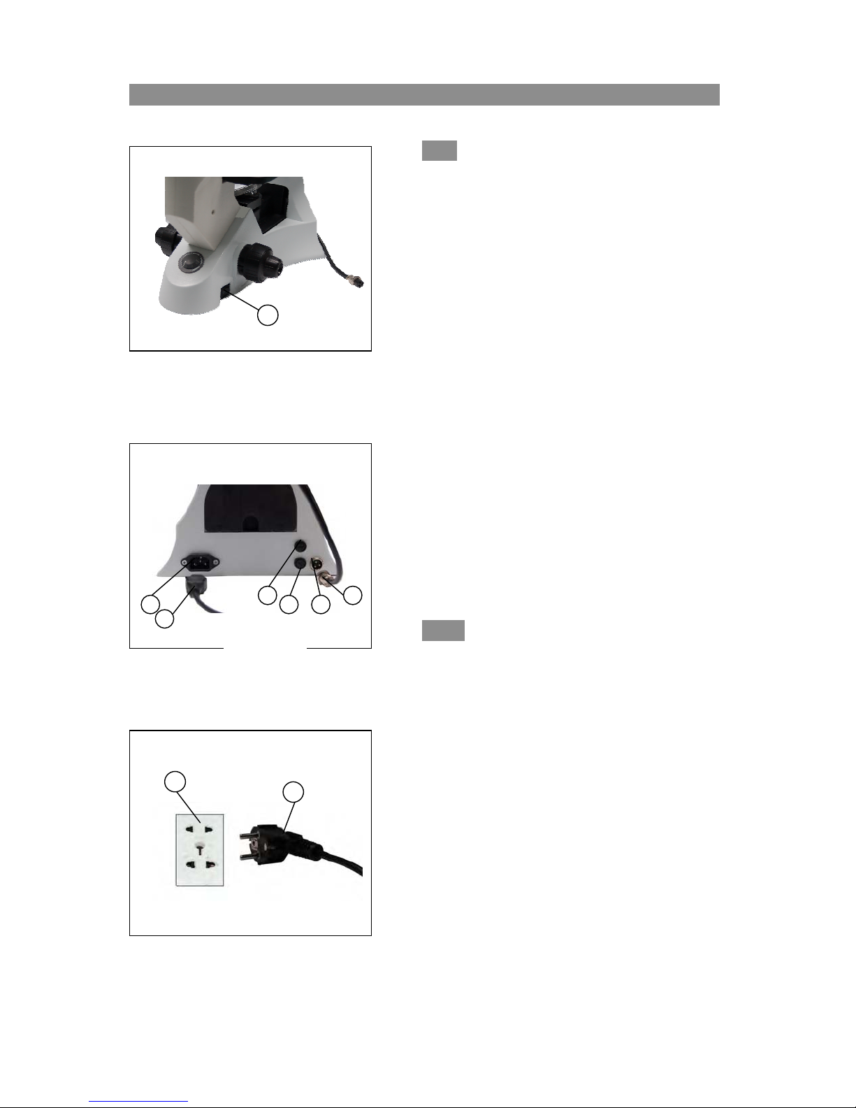
2-2-9 Connecting the Power Cord(
1
Figure 12
and 14))))
★
★ Do not place stress or strain on the power
★ ★
cord. These will damage the cord and cause
a danger to the user.
1. Turn the main switch ① to “O” (off) before
connecting the power cord.
2. Insert the power cord plug ② into the electrical
connector ③.
3. Insert the power cord ④ into an electrical
receptacle (5).
4. Insert the BNC connector plug ⑨ into the BNC
connector jack ⑧.
★★★★ Ensure the power cord is connected to a
grounded receptacle.
(Fig
(
(
12, 13
.
Use of an electrical surge suppressor receptacle
is highly recommended.
Figure 13
2-2-10 Replacing the Fuse (Figures 12 & 13))))
urn the main switch ① to “O”
T
replacing the fuse. Unplug the power cord.
(off) before
Rotate the fuse holder ⑥ out of the base ⑦
5
4
with a flat edge screwdriver, replace the fuse,
then insert the fuse holder and tighten.
★Fuse rating: 250V,,,,500mA.
Figure 14
6
Page 10

3. Adjustment 3032
Diopter ring
Light path selector lever
Light switch
Tension adjustment collar
Aperture diaphragm adjust lever
Phase center bolt
Main switch Coarse focus knob Fine focus knob
Figure 15
Color filter holder
Phase contrast slider
7
Page 11
4. Adjustments 3032
4-1 M
icroscope base
Figure 16
Figure 17
1
1
3
2
1
Figure 18
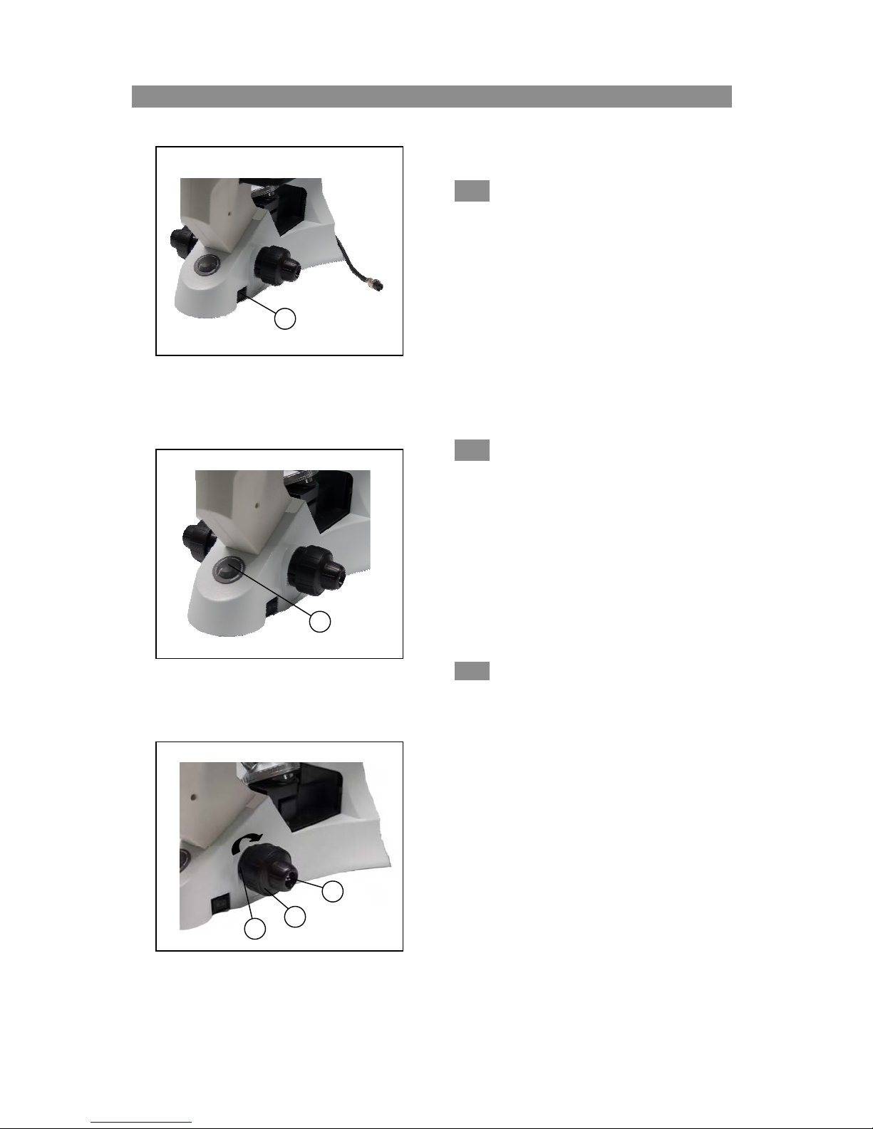
4-1-1 Turning on the Lamp(
(Fig
(
(
Connect the power cord; turn the main switch ①
to “-” (on).
re 16))))
u
4-1-2 Adjusting the Brightness((((Figu
Rotate the variable light intensity dial (Fig. 17-1)
clockwise to increase the brightness. Rotating the dial
counterclockwise reduces the brightness.
Using the lowest feasible brightness will increase
the bulb life.
re 17))))
4-1-3 Adjusting the Tension Adjustment
r((((Figure 18))))
Colla
★
The tension of the coarse focus knob
factory adjusted.
Rotate the tension adjustment collar ① in the
direction shown by the arrow (Figure 18) to increase
the tension of the coarse focus knob ②. Rotating the
collar in the opposite direction will decrease the
tension.
The coarse focus knob is too loose if the nosepiece
drops automatically or if the specimen looses focus
soon after focusing with the fine focus knob ③.
Tighten the tension adjustment collar if either of
these occurs.
②②②②
has been
8
Page 12

3032
4-2 S
tage
3
2
Figure 19
5
Figure 20
1
6
7
4
4-2-1 Viewing the Specimen(
For optimum viewing, ensure the thickness, as
marked on each objective (0.17mm or 1.2mm) is the
same as your container, dish or slide.
Use the appropriate bracket to hold your Terasaki well
plate (3), culture dish (4), flask (5) or slide (5). A larger
flask may be placed directly on the stage. Slides may
also be placed by securing with the slide holder (2).
The specimen is positioned by turning the X (6) and Y (7)
stage movement controls.
(Fig
(
(
res 19 & 20))))
u
9
Page 13

3032
4-3 V
iewing Adjustments
D
Figure 21
Figure 22
2
3
4-3-1
1. Using the 10x objective and your right eye
2. Then observe the specimen with your left eye
The diopter range is ±5
4-3-2 Interpupillary Distance Adjustment
iopter Adjustment(
only, observe your specimen through the right
eyepiece and bring it into focus,
only through the left eyepiece. If the specimen
is not in focus, rotate the diopter ring① until a
sharp image is obtained.
((((Figu
While observing with both eyes, hold the
left and right prism eye tubes. Rotate the
eye tubes around the central axis. The
interpupillary distance is correct when the
left and right fields of view coincide
completely with one image.
The interpupillary distance range is
48-75mm.
(F
(
(
re 22))))
gure 21))))
i
10
Page 14

S
Figure 23
1
4-3-3
★ The light path desired is obtained by pulling out or
● For binocular observation, push the light path selector lever
● For trinocular observation, pull the light path selector lever
Selecto
witching the Light Path(
pushing in the light path selector lever ①.
“in” completely.
“out” completely.
Light Path
r Lever
Illumination
Proportions
(F
g.23))))
i
(
(
Applications
Pushing in the
lever
ompletely
c
Pulling out the
lever
ompletely
c
Epi Fluorescent
Models
100% for
Binocular
observation
20% for
Binocular
observation
and 80% for
Trinocular
observation
100%
Binocular
or
100%
Trinocular
Binocular
observation
Binocular
observation,
video monitor,
computer monitor
and
microphotography
Fluorescence
Applications
11
Page 15
3032
4-4 I
llumination Unit
1
2
Figure 24
70-80%
30-20%
Figure 25
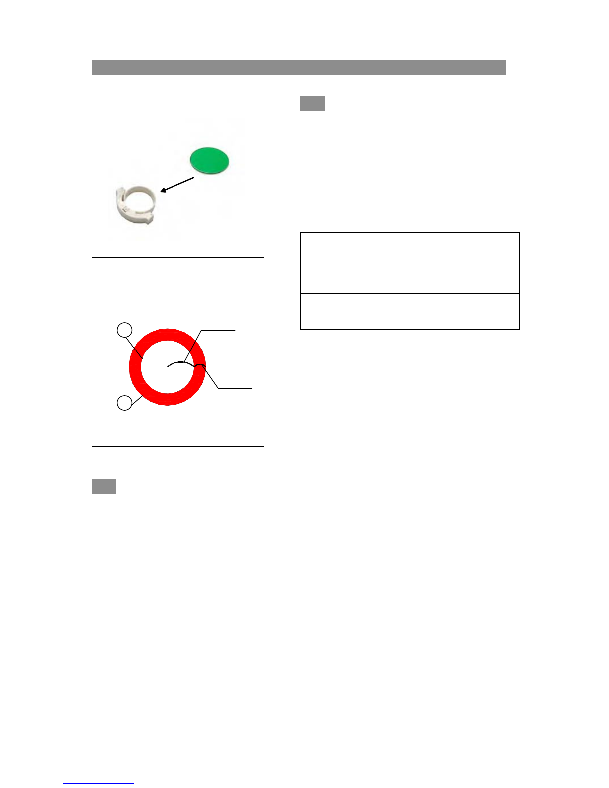
U
4-4-1
Select the appropriate color filter according to the
sing Color Filters(
type of illumination being used. Insert the filter
(F
gure 24))))
i
(
(
into the filter holder.
The filter holder can hold multiple filters up to a
total thickness of 11mm or less.
Color
Filter
IF550
LBD
Us
age in Microscopy
Filter
Green
use for phase contrast microscopy
ilter
Blue F
use for bright field observation and
microphotography
4-4-2 Using the Aperture Diaphragm((((Figu
● When using bright field observation, the aperture diaphragm is used to control the numerical
re 25))))
aperture of the illumination system not the brightness. Only when the numerical apertures of the
objective and the illumination system are equal can higher image resolution, contrast, and
increased depth of field be obtained.
● Generally, when observing the chromatic specimens, the N.A. of the condenser aperture diaphragm
is adjusted to 70-80% of the numerical aperture marked on the objective.
To adjust the aperture diaphragm, remove the eyepiece then looked into the viewing tube. Your field of
view will appear as Figure 25. The proportion may be changed by turning the aperture adjustment
lever: (①is the image of the aperture diaphragm & ② is the edge of the objective).
12
Page 16
5.
hase Contrast Microscopy 3032
.P
.
.
5-1
Nomenclature
Figure 26
1 2
Figure 27
5-1-1
Phase CCCContrast
Phase
Pha
ontrast OOOObjective
se Phase
ontrast ontrast
bjective((((FFFFig
bjectivebjective
The microscope’s standard phase objectives are
10x and 20x. They are mounted on the objective
turret as described in 2-2-4.
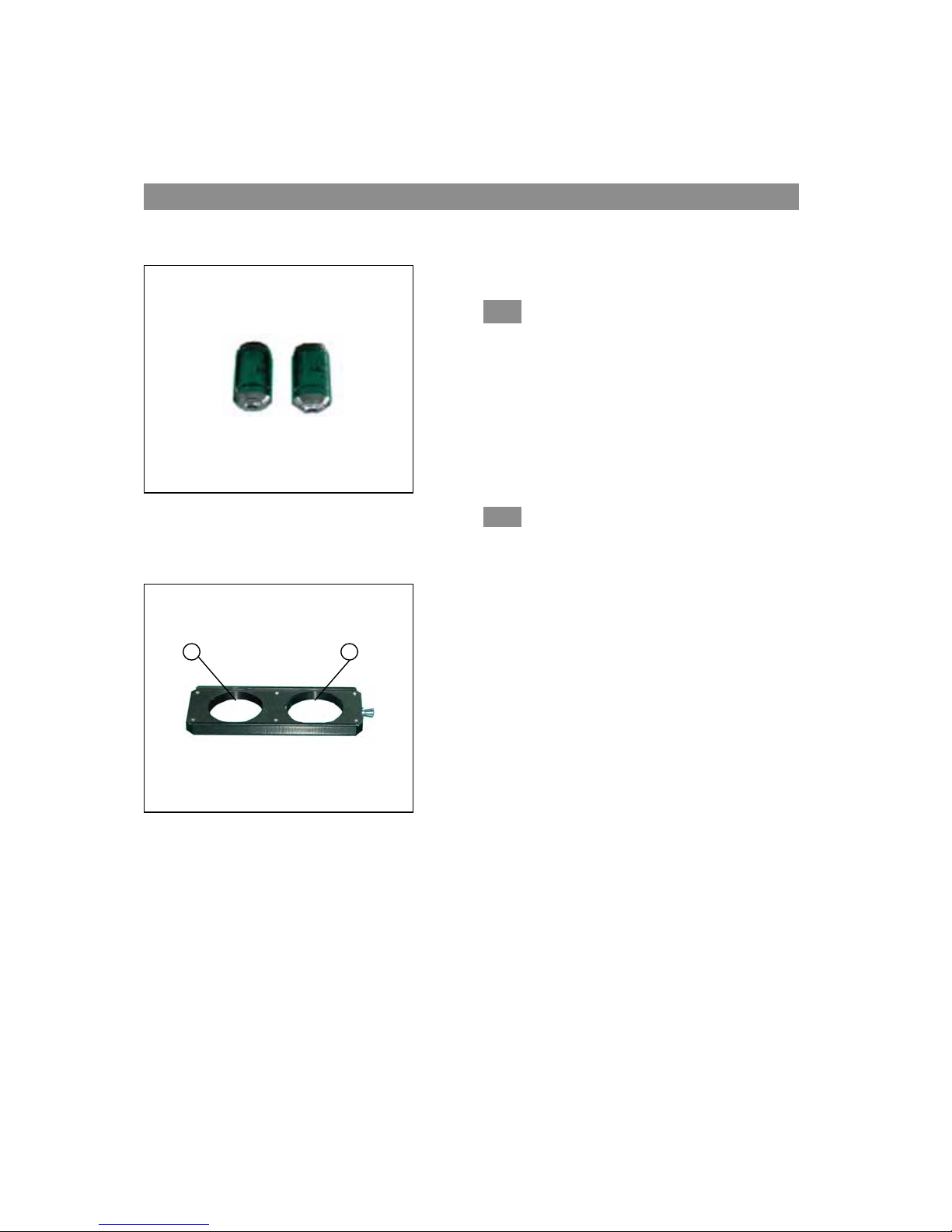
5-1-2 Phase Contrast Annulus Slider
(Figure 27)
● The phase annulus ring has been centered. The phase
annul
us ring may be adjusted by using the centering
telescope as described in 5-2-2.
● The 10X/20X phase ring ① is used with the 10X and
20X phase contrast objectives. The empty opening
② is used for bright field observation.
igure
ure 26
igig
ure ure
26))))
2626
13
Page 17
Phase Contrast Microscopy 3032
5-2 I
nstallation and use
2
1
Figure 28
1
2
Figure 29
3
Figure 30
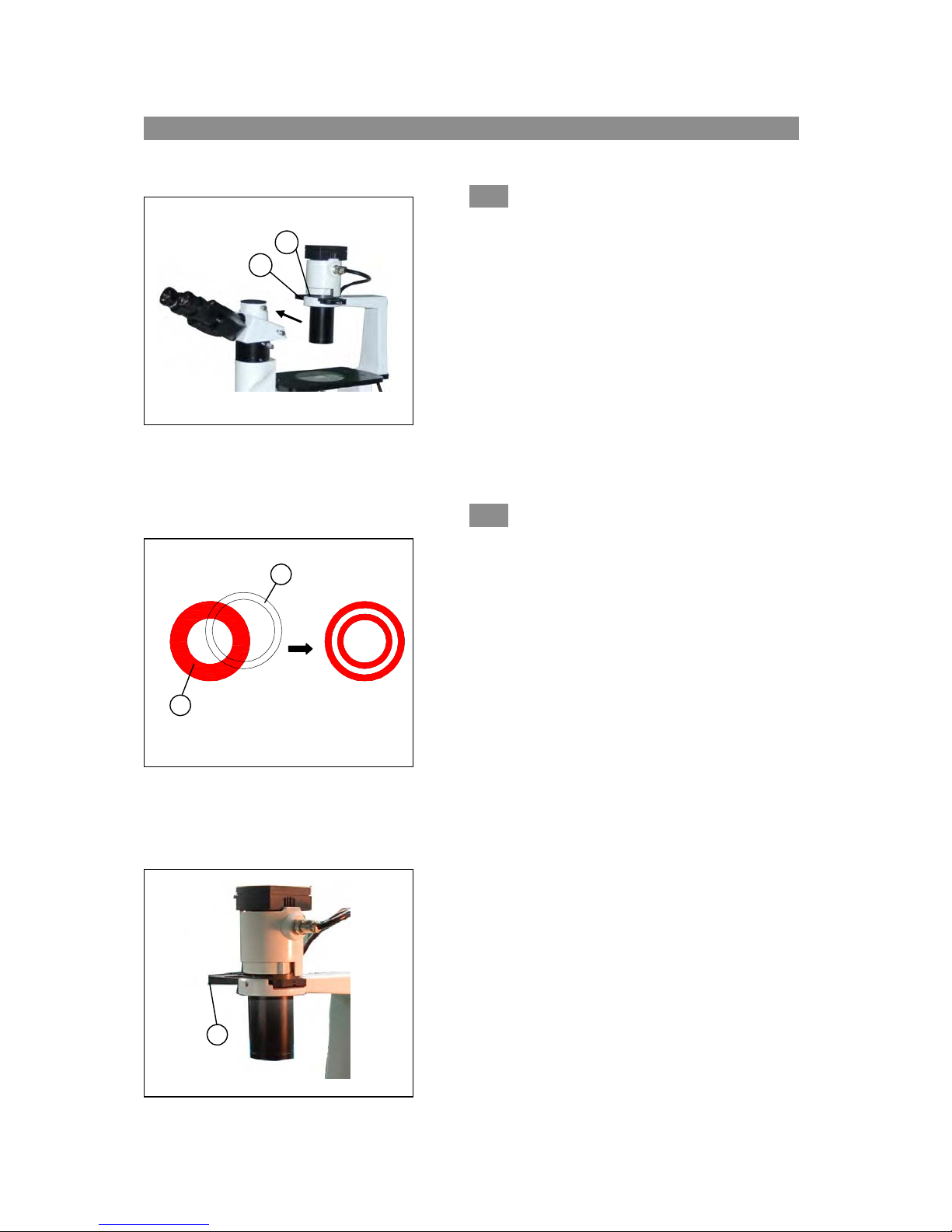
5-2-1 Installing the Phase Contrast Slider(
(Fig
(
(
28))))
1. With the slider ① facing upwards (the surface with
printing), insert it into the illumination system.
2. Brightfield and phase contrast light rings have their
own position. Move the slider until you hear the
“click” to ensure the ring or the opening is centered
in the light path.
3. When observing with a phase contrast objective,
keep the aperture diaphragm adjustment lever ② in
the position “O” (open).
5-2-2Centering Telescope (Figures 29 and 30))))
phase annulus has been pre-centered.
The
Adjustments will usually not be required with
normal usage.
If adjustments are required:
1. Place the specimen on the stage and focus as usual.
2.
Remove the eyepiece without the diopter adjustment
and replace it with the centering telescope.
3. Ensure sure the matched phase contrast objective and
annulus ring in the phase contrast slider are in the
center of the light path.
4. Using the centering telescope to observe the light
ring’s image ① and the phase contrast ring’s
image②. If the light ring’s image is not sharp, turn
the recessed screws in the phase annulus slider until
you can see a clear image of the light ring②
superimposed on light ring (1). The best image will
be obtained only when the two rings coincide.
5. Changing containers, dishes or slides of different
thicknesses will require re-adjustment of the phase
annulus.
u
re
14
Page 18
6....Microscope Video and Photography 3032
6-1
Microscope Video
6-1-1 Selecting the Light Path(
1
Figure 31
Video
CCD
1. For binocular observation, push the light path selector
lever (1) in completely.
2. Focus your specimen as usual.
3. For video or camera usage, pull horizontally on the light
path selector lever until it is completely pulled out.
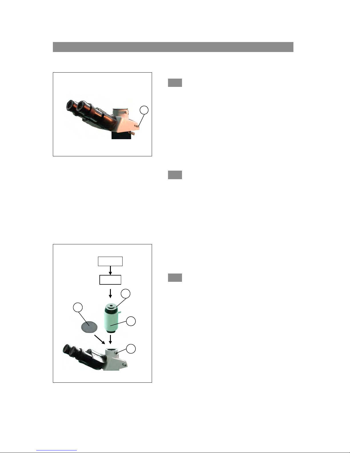
6-1-2 Installing the Video Adapter((((Figu
1. Loosen the locking thumb screw ① on the trinocular
viewing head and remove the protective cap②.
2. Remove the protective caps on the both ends of the
video adapter③.
3. Screw the threaded end into the CCD/CMOS port and
tighten the thumb screw on the adapter (3).
3. Install the accessories into the vertical port and tighten
the thumb screw ①.
4. Attach your video camera to the video port (4).
6-1-3 Focusing((((Figu
re 32))))
(Fig
(
(
u
re 31))))
re 32))))
2
Figure 32
4
3
1
Focus on your specimen while observing through the
eyepieces. Ensure the light path selector lever is fully
pulled out. Observe the image on the video or
computer monitor. If the image is not in focus, turn the
revolving video tube④ until the image is sharp.
14
Page 19
3032
6-2 M
icroscope Photography
2
Figure 33
Camera
4
3
1
6-2-1 Selecting the Light Path (Figure 31)
1. Fo
r binocular observation, push in completely the
light path selector lever (1).
2. Focus your specimen as usual.
3. For microphotography, pull horizontally on the light
path selector lever until it is completely pulled out.
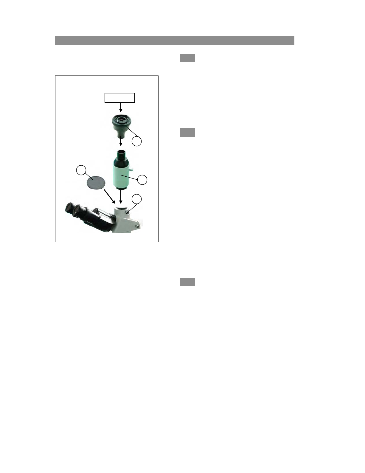
6-2-2 Installing the Photo Camera(
(Fig
(
(
1. Loosen the locking thumb screw① on the
trinocular viewing head and remove the
protective cap②.
2. Install the adapter③ into the vertical port, and
tighten the thumb screw ①.
3. Insert the camera adapter into ④ into the camera
port.
● Camera magnification = objective magnification x
camera
★ The shutter on some cameras may cause a jarring
lens magnification
impact when photographing through the
microscope. To weaken the impact and obtain a
clear image, select a longer exposure time.
6-2-3 Focusing
cus as usual in the binocular mode. When using the
Fo
microscope for photography, use the camera’s viewfinder
to focus the specimen. Please refer to the camera’s user
manual for additional details.
15
re 33))))
u
Page 20
7.Specifications 3032
Optical
Sy
stem
Viewing
Head
Eyepiece Wide Field Eyepiece 10X; 22 mm field of view
Nosepiece Reversed Quintuple Nosepiece
Objectives
Focusing
m
Syste
Mechanical
Stage
Illumination Halogen Lamp 6volt 30watt; Variable intensity
Condenser Long working Distance Condenser, N.A. 0.3; Working Distance 72mm
tive Specifications
Objec
TYPE
Infinity
Long
orking
W
Distance
Plan
Achromatic
Objective
Infinity
Long
orking
W
Distance
Plan Phase
Contrast
Objective
Infinity Optical System
C
ompensation Free Trinocular Head Inclined 30º
Division ratio: 20% for Binocular Viewing and 80% for Video Imaging &
Microphotography
Infin
ity Long Working Distance Plan Achromatic: 4X & 40X
Infinity Long Working Distance Plan Phase Contrast: 10X & 20X
Coaxial Coarse and Fine Focusing System
Sensitivity and Graduation of Fine Focus: 0.002mm
Movement Range(from the surface focus of stage plate): up 8mm, down 3mm
Size: 250mm x 160mm
Movement Range: 120mm(width)×78mm(length)
MAGNIFICATION
4X 0.1 25.2 ∞ 45 ─
40X 0.6 3
10X 0.25 11 ∞ 45 0.17mm
20X 0.4 6 ∞ 4
NUMERICAL
APERTU
(N.A)
RE
WORKING
DISTANCE
(mm)
.2 ∞ 45 1.2mm
CONJUGATE
DISTANCE
(mm)
FOCUS
DISTANCE
(mm)
5 0.17mm
THICKNESS
COVER
SLIP
16
Page 21

TROUBLESHOOTING GUIDE
If a
problem occurs during the course of use, please refer to the tables below
before contacting your distributor.
OPTICAL
Problem Cause
Darkness at the periphery Revolving nosepiece not in
or uneven brightness in the click stop position swingi
field of view
Dirt or dust on the viewfield Dirt or dust on the lens - Clean the lens
eyepiece
objecti
specime
Poor image quality No cove
the sl
Covergl
Slide m
glass
Immersio
objecti
No imme
100xR
Air bub
Conden
or open
Conden
low the
Image moves while focusing Specimen rises from stage Secure the specimen in the
surface s
Revolv
in the
Image tinged yellow Blue fi
co
, condenser,
ve, collector lens or
n
rglass attached to Attach a 0.17mm coverglass
ide
ass is too thick or thin Use a coverglass of the
ay be upside down Turn slide over so the cover-
n oil is on a dry Check the objectives, clean
ve (especially the 40xR) if necessary
rsion oil used with Use immersion oil
objective
bles in immersion oil Remove bubbles
ser aperture is closed Open or close properly
too much
ser is positioned too Position the condenser at
IMAGE PROBLEMS
ing nosepiece is not Revolve the nosepiece to the
click-stop position click-stop position
lter not used Use daylight blue filter
C
orrective Measure
v
Revol
click-stop position by
approp
(0.17mm)
e the nosepiece to
g the objective
n
y
rrectl
lide holder
into the optical path
riate thickness
faces up
upper limit
Page 22

IMAGE PROBLEMS
Problem Cause
Image tinged yellow Lamp
Image is too bright Lamp
Insufficient brightness Lamp intensity is too low Adjust the light intensity by
rotat
dial
Aperture
too f
Conde
the
Image will not focus with Slide upside down Turn t
high power objectives cover
Cover
High power objective contacts Slide upside down Turn t
slide when changed from cover
low power objective
Cover
Diopt
properl
Lamp does not light when No electrical power Check p
switched on
Lamp
Fuse
Slippage of focus when using Tension adjustment is set too Increase the tension on the
the coarse focusing knob low focusi
Fine focus is ineffective Tension adjustment is set too Loosen the tension on the
high f
intensity is too low Adjust the light intensity by
rota
dia
intensity is too high Adjust the light intensity by
rota
dia
diaphragm closed Open to the proper setting
ar
nser position too low Position the condenser at
MECHANICAL PROBLEMS
glass is to thick Use a 0.17mm cover glass
glass is to thick Use a 0.17mm cover glass
er adjustment is not set Readjust the diopter settings
y
bulb burnt out Replace bulb
blown out Replace fuse
Corrective Measure
ing the intensity control
t
l
ing the intensity control
t
l
ing the intensity control
upper limit
he slide over so the
glass faces up
he slide over so the
glass faces up
ower cord connection
ng knobs
ocusing knobs
Page 23

Order online anytime at www.polysciences.com
US Headquarters
400 Valley Road
Warrington, PA 18976
European Headquarters
Handelsstrasse 3
D-69214 Eppelheim
Germany
Asia-Pacific Headquarters
Polysciences Asia Pacific, Inc.
2F-1, 207 DunHua N. Rd.
Taipei, Taiwan 10595
(800) 523-2575 / (215) 343-6484
(800) 343-3291 / (215) 343-0214 fax
info@polysciences.com
www.polysciences.com
(49) 6221-765767
(49) 6221-764620 fax
info@polysciences.de
(886) 2 8712 0600
(886) 2 8712 2677 fax
info@polysciences.tw
Our catalog lists over 3,000 unique and specialty products that are used by histology professionals, lab technicians,
pathologists, chemists and scientists worldwide. Visit www.polysciences.com to learn more about our product lines.
 Loading...