

Page 1
221=192=010
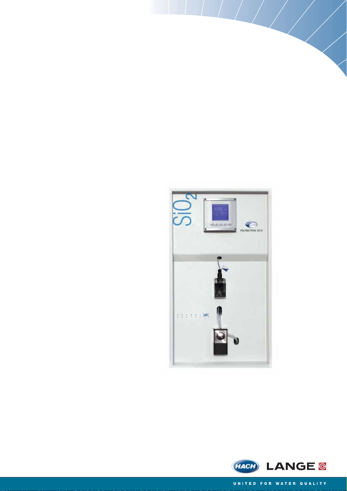
POLYMETRON Model 9210
Silica Analyzer
USER MANUAL
May 2009, Revision K
Page 2

Page 3

Table of Contents
Section 1 General Information.........................................................................................................5
1.1 Disclaimer .................................................................................................................................... 5
1.2 Safety information ........................................................................................................................ 5
1.2.1 Use of hazard information................................................................................................... 5
1.2.2 Safety recommendations ....................................................................................................5
1.2.3 Service and repairs .............................................................................................................6
1.2.4 Precautionary labels............................................................................................................6
1.3 Product recycling information....................................................................................................... 7
1.4 Product disposal .......................................................................................................................... 9
1.5 Restriction of hazardous substances (RoHS) ............................................................................10
Section 2 Specifications..................................................................................................................11
2.1 Technical specifications.............................................................................................................11
Section 3 Analyzer Overview ......................................................................................................... 13
3.1 Operation ................................................................................................................................... 13
3.2 Calibration..................................................................................................................................14
3.3 Analyzer outputs ........................................................................................................................ 14
3.4 Maintenance ..............................................................................................................................14
3.5 Presentation...............................................................................................................................15
3.5.1 Front panel........................................................................................................................ 15
3.5.2 Rear panel......................................................................................................................... 16
Section 4 Installation........................................................................................................................17
4.1 Analyzer inspection and unpacking ........................................................................................... 17
4.2 Analyzer preparation..................................................................................................................17
4.3 Installation checklist ...................................................................................................................17
4.4 Mounting the analyzer................................................................................................................18
4.4.1 Panel version ....................................................................................................................18
4.4.2 Cabinet version................................................................................................................. 19
4.5 Installing the canister holder ...................................................................................................... 20
4.6 Connecting the sample .............................................................................................................. 21
4.7 Connecting the drain tube..........................................................................................................22
4.8 Mains power connection ............................................................................................................ 22
4.9 External communications connection ........................................................................................26
4.10 Input/Output connections ......................................................................................................... 27
4.11 Reagent preparation ................................................................................................................ 29
4.11.1 Reagent 1M - Molybdate (2 liters)...................................................................................29
4.11.2 Reagent 1A - Nitric acid (2 liters) .................................................................................... 29
4.11.3 Reagent 2 - Oxalic acid...................................................................................................29
4.11.4 Reagent 3 - Reducing reagent........................................................................................ 30
4.11.5 Calibration solution.......................................................................................................... 30
4.12 Connecting the canisters .........................................................................................................31
4.13 Analyzer startup ....................................................................................................................... 32
4.13.1 Reagents volume declaration..........................................................................................32
4.13.2 Flow rate adjustment....................................................................................................... 32
4.13.3 System and user setup procedures ................................................................................32
Section 5 Operating Instructions..................................................................................................33
5.1 Data Entry .................................................................................................................................. 33
5.1.1 Function Keys ...................................................................................................................33
5.1.2 Modification of a value ...................................................................................................... 33
5.2 Measurement screens ...............................................................................................................33
5.2.1 Main screen....................................................................................................................... 33
5.2.2 Display screen 2 - Measurement history...........................................................................34
5.2.3 Display screen 3 - Alarms .................................................................................................34
5.2.4 Display screen 4 - Graph ..................................................................................................34
5.3 Main menu ................................................................................................................................. 35
1
Page 4

Table of Contents
5.4 Analyzer menu overview ............................................................................................................36
Section 6 System Setup...................................................................................................................37
6.1 Menu overview ...........................................................................................................................37
6.1.1 Time ..................................................................................................................................37
6.1.2 Display...............................................................................................................................38
6.1.3 Code..................................................................................................................................38
6.1.4 Soft issues.........................................................................................................................39
6.1.5 Default values....................................................................................................................39
6.1.6 mA adjustments.................................................................................................................39
6.1.7 Factory ..............................................................................................................................40
Section 7 User Setup........................................................................................................................41
7.1 Measure menu overview ............................................................................................................41
7.1.1 Measuring mode................................................................................................................41
7.1.2 Grab sample......................................................................................................................42
7.1.3 Historic ..............................................................................................................................42
7.1.4 ADC values .......................................................................................................................43
7.2 Alarms menu overview...............................................................................................................43
7.2.1 Alarms 1 to 6 .....................................................................................................................44
7.2.2 Warning alarm ...................................................................................................................45
7.2.3 System alarm ....................................................................................................................45
7.2.4 Alarm conditions................................................................................................................46
7.3 mA outputs menu overview........................................................................................................47
7.3.1 Affect .................................................................................................................................47
7.3.2 Special programming ........................................................................................................48
7.3.3 Test ...................................................................................................................................49
7.4 RS485 ........................................................................................................................................49
7.5 Sequence ...................................................................................................................................50
7.5.1 Channel activation.............................................................................................................50
7.5.2 Sequence ..........................................................................................................................50
Section 8 Calibration........................................................................................................................51
8.1 Menu overview ...........................................................................................................................51
8.1.1 Programming (automatic calibration) ................................................................................52
8.1.2 Execution primary calibration ............................................................................................53
8.1.3 Execution manual calibration ............................................................................................53
8.1.4 Parameters........................................................................................................................54
8.1.5 Historic ..............................................................................................................................54
8.1.6 Calibration results..............................................................................................................55
Section 9 M aintenance.....................................................................................................................57
9.1 General.......................................................................................................................................57
9.2 Cleaning overview......................................................................................................................57
9.2.1 General cleaning process..................................................................................................57
9.2.2 Chemical cleaning procedure............................................................................................58
9.3 Battery replacement ...................................................................................................................59
9.4 Fuse replacement.......................................................................................................................59
9.5 Yearly maintenance....................................................................................................................60
9.6 Maintenance menu overview......................................................................................................63
9.7 Startup........................................................................................................................................64
9.8 Reagents refill ............................................................................................................................64
9.9 Extended stop ............................................................................................................................65
9.10 Tube cleaning...........................................................................................................................65
9.11 Photometer test........................................................................................................................66
9.12 Pumps - others.........................................................................................................................66
9.13 Pumps flowrate.........................................................................................................................66
2
Page 5

Table of Contents
9.14 Solenoid valves........................................................................................................................67
9.15 Relays ...................................................................................................................................... 67
9.16 Logical inputs ........................................................................................................................... 67
9.17 Preparation of the tubes for insertion in the fast connectors.................................................... 68
Section 10 Troubleshooting........................................................................................................... 69
10.1 Possible sources of the problem..............................................................................................69
10.2 Possible solutions .................................................................................................................... 69
10.3 Typical measurement values during calibration....................................................................... 70
Section 11 Spare Parts.....................................................................................................................71
Section 12 Default Configuration..................................................................................................73
Section 13 Material Safety Data Sheets (MSDS)........................................................................ 77
13.1 Oxalic acid ............................................................................................................................... 77
13.2 Sulfuric acid (98%)...................................................................................................................78
13.3 Nitric acid (50-70%) ................................................................................................................. 80
13.4 Ammonium hydroxide (10-35% NH3) ......................................................................................84
13.5 Sodium hexafluorosilicate ........................................................................................................88
13.6 Ferrous ammonium sulfate hexahydrate ................................................................................. 89
13.7 Sodium molybdate dihydrate ................................................................................................... 91
13.8 Reagent R1A ...........................................................................................................................92
13.9 Reagent R1M...........................................................................................................................94
13.10 Reagent R2............................................................................................................................96
13.11 Reagent R3............................................................................................................................98
13.12 Lithium battery safety precautions .......................................................................................100
3
Page 6

Table of Contents
4
Page 7

Section 1 General Information
1.1 Disclaimer
The information in this manual has been carefully checked and is believed to be accurate.
However, Hach Lange assumes no responsibility for any inaccuracies that may be contained in
this manual. In no event will Hach Lange be liable for direct, indirect, special, incidental, or
consequential damages resulting from any defect or omission in this manual, even if advised of
the possibility of such damages. In the interest of continued product development, Hach Lange
reserves the right to make improvements in this manual and the products it describes at any
time, without notice or obligation.
Copyright © 2009 by Hach Lange. All rights reserved. No part of the contents of this manual
may be reproduced or transmitted in any form or by any means without the written permission of
Hach Lange.
1.2 Safety information
Read this entire manual before unpacking, setting up or operating this equipment. Pay attention
to all danger and caution statements. Failure to do so could result in serious injury to the
operator or damage to the equipment.
To make sure that the protection provided by this equipment is not impaired, do not use or install
this equipment in any manner other than that specified in this manual.
Note: This equipment has been tested and found to comply with the limits for Class A digital device,
pursuant to Part 15 of the FCC Rules. These limits are designed to provide reasonable protection against
harmful interference when the equipment is operated in a commercial environment. This equipment
generates, uses, and can radiate radio frequency energy and, if not installed and used in accordance with
the instruction manual, may cause harmful interference to radio communications. Operation of this
equipment in a residential area is likely to cause harmful interference in which case the user will be required
to correct the interference at his own expense.
1.2.1 Use of hazard information
WARNING
A warning is used to indicate a condition which, if not met, could cause serious personal
injury and/or death. Do not move beyond a warning until all conditions have been met
CAUTION
A caution is used to indicate a condition which, if not met, could cause minor or
moderate personal injury and/or damage to the equipment. Do not move beyond a
caution until all conditions have been met.
Note: A note is used to indicate important information or instructions that should be considered
before operating the equipment.
1.2.2 Safety recommendations
For safe operation, it is imperative that these service instructions be read before use and that
the safety recommendations mentioned herein be scrupulously respected. If repairs or
adjustments are necessary, the analyzer should be returned to an authorized Hach Lange
service center.
If danger warnings are not heeded to, serious material or bodily injury could occur.
WARNING
In accordance with safety standards, it must be possible to disconnect the power supply
of the analyzer in its immediate vicinity.
WARNING
The installation of the analyzer should be performed exclusively by personnel
specialized and authorized to work on electrica l installa tions, in a ccordance with re levan t
local regulations.
5
Page 8
General Information
1.2.3 Service and repairs
None of the analyzer’s components can be serviced by the user. Only personnel from Hach
Lange or its approved representative(s) is (are) authorized to attempt repairs to the system and
only components formally approved by the manufacturer should be used. Any attempt at
repairing the analyzer in contravention of these principles could cause damage to the analyzer
and corporal injury to the person carrying out the repair. It renders the warranty null and void
and could compromise the correct working of the analyzer and the electrical integrity or the CE
compliance of the analyzer.
If you have any problems with installation, starting, or using the analyzer please contact the
company that sold it to you. If this is not possible, or if the results of this approach are not
satisfactory, please contact the manufacturer’s Customer Service.
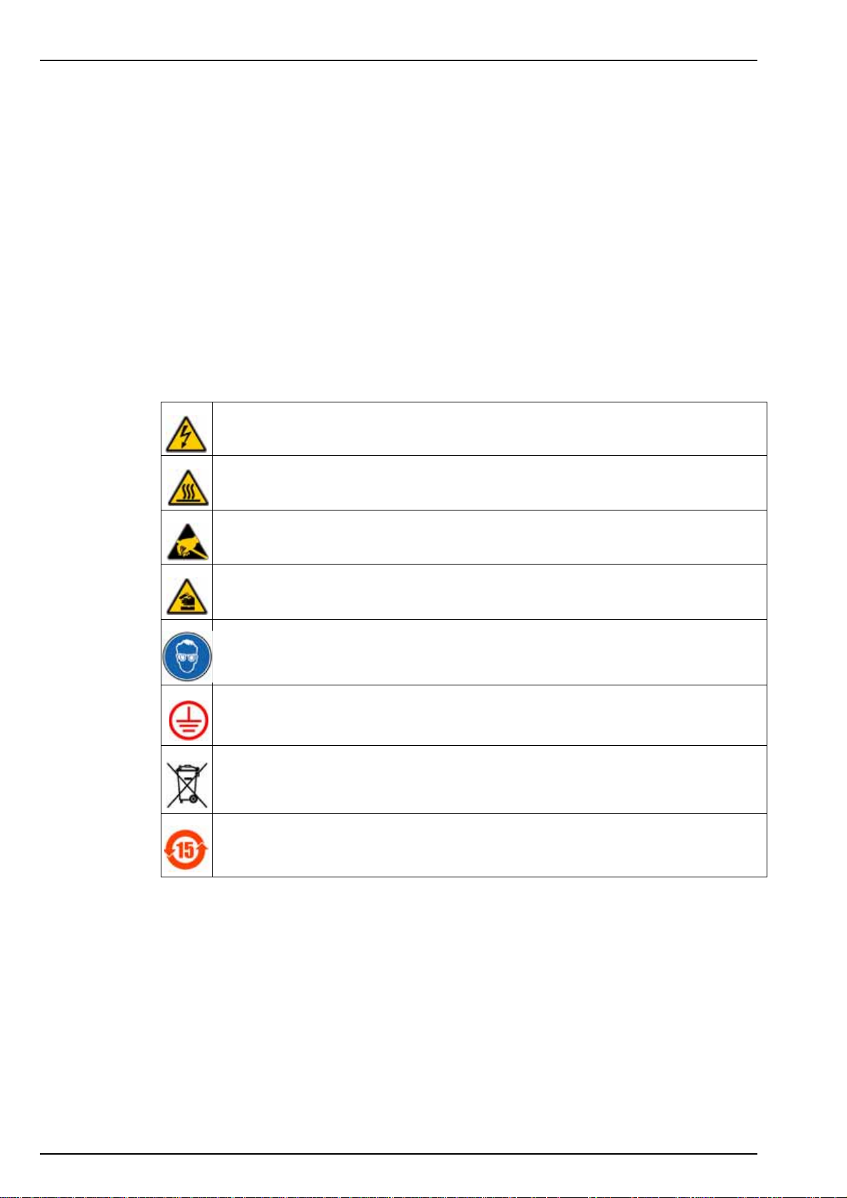
1.2.4 Precautionary labels
Read all labels and tags attached to the analyzer. Personal injury or damage to the analyzer
could occur if not observed.
This symbol, when noted on a product enclosure or barrier, indicates that a risk of electrical
shock and/or electrocution exists and indicates that only individuals qualified to work with
hazardous voltages should open the enclosure or remove the barrier.
This symbol, when noted on the product, indicates that the marked item can be hot and should
not be touched without care.
This symbol, when noted on the product, indicates the presence of devices sensitive to
electrostatic discharge and indicates that care must be taken to prevent damage to them.
This symbol, when noted on the product, identifies a risk of chemical harm and indicates that
only individuals qualified and trained to work with chemicals should handle chemicals or perform
maintenance on chemical delivery systems associated with the equipment.
This symbol, if noted on the product, indicates the need for protective eye wear.
This symbol, when noted on the product, identifies the location of the connection for protective
earth (ground).
Electrical equipment marked with this symbol may not be disposed of in European public
disposal systems. In conformity with European local and national regulations, European
electrical equipment users must now return old or end-of-life equipment to the manufacturer for
disposal at no charge to the user.
Products marked with this symbol indicates that the product contains toxic or hazardous
substances or elements. The number inside the symbol indicates the environmental protection
use period in years.
6
Page 9
1.3 Product recycling information
ENGLISH
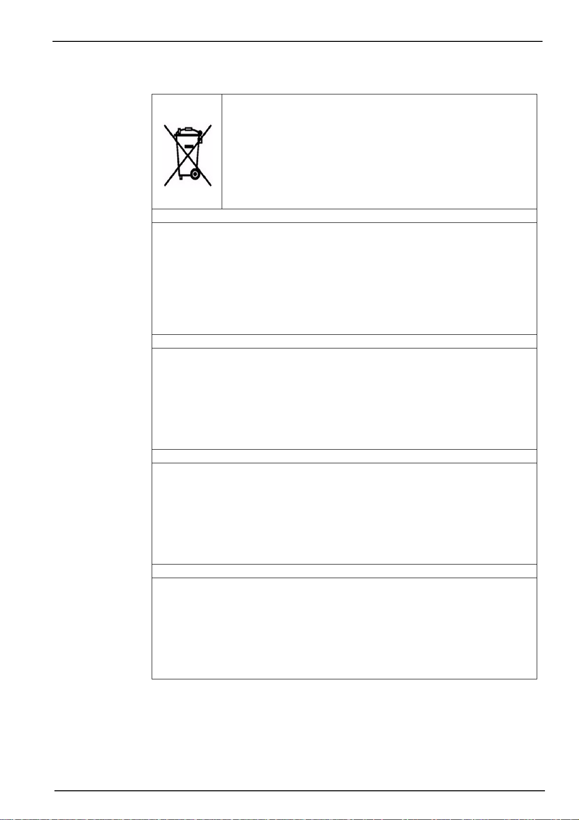
Electrical equipment marked with this symbol may not be disposed of in
European public disposal systems after 12 August 2005. In conformity with
European local and national regulations (EU Directive 2002/96/EC), European
electrical equipment users must now return old or end-of-life equipment to the
manufacturer for disposal at no charge to the user.
Note: For return for recycling, please contact the equipment
manufacturer or supplier for instructions on how to return end-of-life
equipment for proper disposal.
DEUTSCH
Elektrogeräte, die mit diesem Symbol gekennzeichnet sind, dürfen in Europa nach dem 12.
August 2005 nicht mehr über die öffentliche Abfallentsorgung entsorgt werden. In
Übereinstimmung mit lokalen und nationalen europäischen Bestimmungen (EU-Richtlinie
2002/96/EC), müssen Benutzer von Elektrogeräten in Europa ab diesem Zeitpunkt alte bzw. zu
verschrottende Geräte zur Entsorgung kostenfrei an den Hersteller zurückgeben.
Hinweis: Bitte wenden Sie sich an den Hersteller bzw. an den Händler, von dem Sie das Gerät
bezogen haben, um Informationen zur Rückgabe des Altgeräts zur ordnungsgemäßen
Entsorgung zu erhalten.
General Information
FRANCAIS
A partir du 12 août 2005, il est interdit de mettre au rebut le matériel électrique marqué de ce
symbole par les voies habituelles de déchetterie publique. Conformément à la réglementation
européenne (directive UE 2002/96/EC), les utilisateurs de matériel électrique en Europe doivent
désormais retourner le matériel usé ou périmé au fabricant pour élimination, sans frais pour
l'utilisateur.
Remarque: Veuillez vous adresser au fabricant ou au fournisseur du matériel pour les
instructions de retour du matériel usé ou périmé aux fins d'élimination conforme.
ITALIANO
Le apparecchiature elettriche con apposto questo simbolo non possono essere smaltite nelle
discariche pubbliche europee successivamente al 12 agosto 2005. In conformità alle normative
europee locali e nazionali (Direttiva UE 2002/96/EC), gli utilizzatori europei di apparecchiature
elettriche devono restituire al produttore le apparecchiature vecchie o a fine vita per lo
smaltimento senza alcun costo a carico dell’utilizzatore.
Nota: Per conoscere le modalità di restituzione delle apparecchiature a fine vita da riciclare,
contattare il produttore o il fornitore dell’apparecchiatura per un corretto smaltimento.
DANSK
Elektriske apparater, der er mærket med dette symbol, må ikke bortskaffes i europæiske offentlige
affaldssystemer efter den 12. august 2005. I henhold til europæiske lokale og nationale regler
(EU-direktiv 2002/96/EF) skal europæiske brugere af elektriske apparater nu returnere gamle eller
udtjente apparater til producenten med henblik på bortskaffelse uden omkostninger for brugeren.
Bemærk: I forbindelse med returnering til genbrug skal du kontakte producenten eller
leverandøren af apparatet for at få instruktioner om, hvordan udtjente apparater bortskaffes
korrekt.
7
Page 10

General Information
SVENSKA
Elektronikutrustning som är märkt med denna symbol kanske inte kan lämnas in på europeiska
offentliga sopstationer efter 2005-08-12. Enligt europeiska lokala och nationella föreskrifter
(EU-direktiv 2002/96/EC) måste användare av elektronikutrustning i Europa nu återlämna gammal
eller utrangerad utrustning till tillverkaren för kassering utan kostnad för användaren.
Obs! Om du ska återlämna utrustning för återvinning ska du kontakta tillverkaren av utrustningen
eller återförsäljaren för att få anvisningar om hur du återlämnar kasserad utrustning för att den ska
bortskaffas på rätt sätt.
ESPANOL
A partir del 12 de agosto de 2005, los equipos eléctricos que lleven este símbolo no deberán ser
desechados en los puntos limpios europeos. De conformidad con las normativas europeas
locales y nacionales (Directiva de la UE 2002/96/EC), a partir de esa fecha, los usuarios
europeos de equipos eléctricos deberán devolver los equipos usados u obsoletos al fabricante de
los mismos para su reciclado, sin coste alguno para el usuario.
Nota: Sírvase ponerse en contacto con el fabricante o proveedor de los equipos para solicitar
instrucciones sobre cómo devolver los equipos obsoletos para su correcto reciclado.
NEDERLANDS
Elektrische apparatuur die is voorzien van dit symbool mag na 12 augustus 2005 niet meer
worden afgevoerd naar Europese openbare afvalsystemen. Conform Europese lokale en
nationale wetgegeving (EU-richtlijn 2002/96/EC) dienen gebruikers van elektrische apparaten
voortaan hun oude of afgedankte apparatuur kosteloos voor recycling of vernietiging naar de
producent terug te brengen.
Nota: Als u apparatuur voor recycling terugbrengt, moet u contact opnemen met de producent of
leverancier voor instructies voor het terugbrengen van de afgedankte apparatuur voor een juiste
verwerking.
POLSKI
Sprzęt elektryczny oznaczony takim symbolem nie może być likwidowany w europejskich
systemach utylizacji po dniu 12 sierpnia 2005. Zgodnie z europejskimi, lokalnymi i państwowymi
przepisami prawa (Dyrektywa Unii Europejskiej 2002/96/EC), użytkownicy sprzętu elektrycznego
w Europie muszą obecie przekazywać Producentowi stary sprzęt lub sprzęt po okresie
użytkowania do bezpłatnej utylizacji.
Uwaga: Aby przekazać sprzęt do recyklingu, należy zwrócić się do producenta lub dostawcy
sprzętu w celu uzyskania instrukcji dotyczących procedur przekazywania do utylizacji sprzętu po
okresie użytkownia.
PORTUGUES
Qualquer equipamento eléctrico que ostente este símbolo não poderá ser eliminado através dos
sistemas públicos europeus de tratamento de resíduos sólidos a partir de 12 de Agosto de 2005.
De acordo com as normas locais e europeias (Directiva Europeia 2002/96/EC), os utilizadores
europeus de equipamentos eléctricos deverão agora devolver os seus equipamentos velhos ou
em fim de vida ao produtor para o respectivo tratamento sem quaisquer custos para o utilizador.
Nota: No que toca à devolução para reciclagem, por favor, contacte o produtor ou fornecedor do
equipamento para instruções de devolução de equipamento em fim de vida para a sua correcta
eliminação.
8
Page 11

1.4 Product disposal
Note: The following only applies to European customers.
Hach Lange is committed to ensuring that the risk of any environmental damage or pollution
caused by any of its products is minimized as far as possible. The European Waste Electrical
and Electronic Equipment (WEEE) Directive (2002/96/EC) that came into force on August 13
2005 aims to reduce the waste arising from electrical and electronic equipment; and improve the
environmental performance of all those involved in the life cycle of electrical and electronic
equipment.
In conformity with European local and national regulations (EU Directive 2002/96/EC stated
above), electrical equipment marked with the above symbol may not be disposed of in
European public disposal systems after 12 August 2005.
Hach Lange will offer to take back (free of charge to the customer) any old, unserviceable or
redundant analyzers and systems which carry the above symbol, and which were originally
supplied by Hach Lange. Hach Lange will then be responsible for the disposal of this
equipment.
General Information
In addition, Hach Lange will offer to take back (at cost to the customer) any old, unserviceable
or redundant analyzers and systems which do not carry the above symbol, but which were
originally supplied by Hach Lange. Hach Lange will then be responsible for the disposal of this
equipment.
Should you wish to arrange for the disposal of any piece of equipment originally supplied by
Hach Lange, please contact your supplier or our After Sales Service department in Geneva for
instructions on how to return this equipment for proper disposal.
9
Page 12
General Information
1.5 Restriction of hazardous substances (RoHS)
The European Union RoHS Directive and subsequent regulations introduced in member states
and other countries limits the use of six hazardous substances used in the manufacturing of
electrical and electronic equipment.
Currently, monitoring and control instruments do not fall within the scope of the RoHS Directive,
however Hach Lange has taken the decision to adopt the recommendations in the Directive as
the target for all future product design and component purchasing.
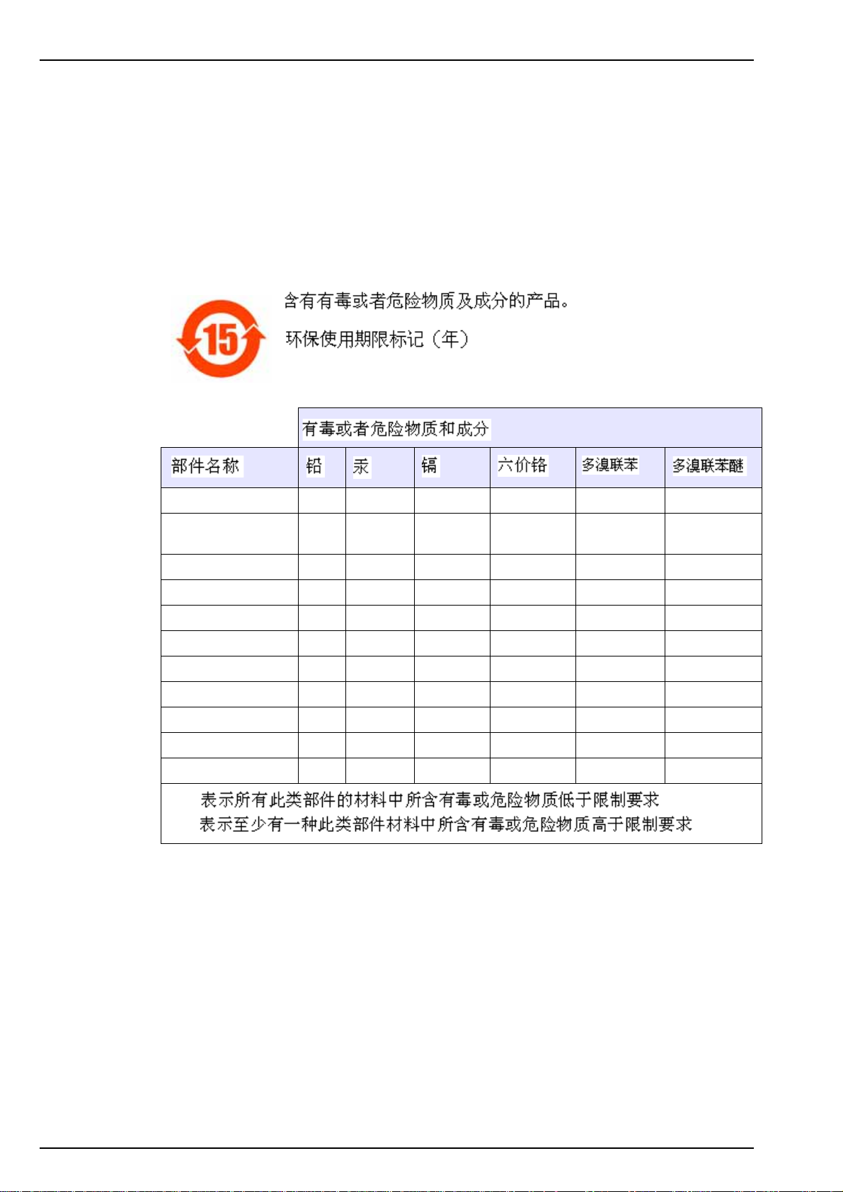
Note: The following only applies to exports of this product into the People’s Republic of China.
Transmitter box X
CPU PCB
(with battery)
Power PCB O O
RS 485 O
Profibus O
PCB CAN O
PCB Local controller O
PCB Measure O
PCB Pumps O
PCB Mixer O
PCB Channel O
OO
O:
X:
10
Page 13
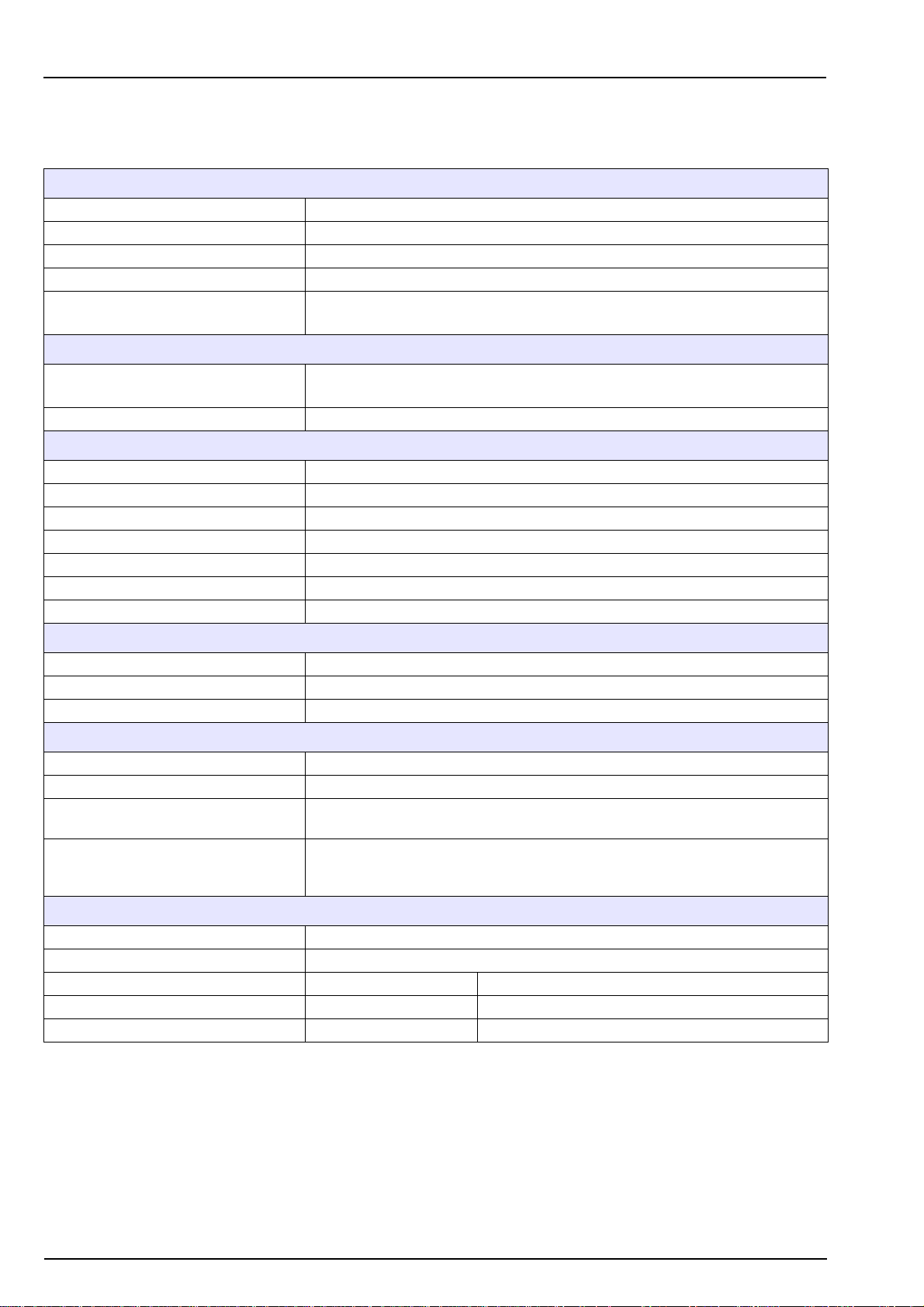
Section 2 Specifications
2.1 Technical specifications
Specifications are subject to change without notice.
Sample
Number of channels 1 - 6
Measurement cycle < 10 min / channel
Sample pressure 0.2 to 6 bar (3 to 87 psi)
Temperature 5 - 50°C (41 - 122°F)
Sample flow
Connections
Sample input
Sample output Barbed stem for 12 mm (½" I.D.) hose
Conditions of use
Ambient temperature 5 to + 45°C (41 to 113°F)
Power supply voltage fluctuation ± 10%
Overvoltage category 2 (according to standard EN 61010-1)
Degree of pollution 2 (according to CEI 664)
Altitude ≤ 2000 m
Relative humidity 10 to 80%
Measurement category Cat II, Class 1 (overvoltage < 1500V)
Weight
Panel analyzer without canister 13 kg
Cabinet analyzer without canister 65 kg
Full canisters 8 kg
Minimum 5L / hour
Maximum 30L / hour
Simple fittings for 6 mm O.D. tubing or ¼" O.D. in PE-low density.
¼" OD in PHED-PTFE-SS as option
Standards
EMC EN 61326-1 (1997) & A1 (1998) & A2 (2001) & A3 (2004)
European safety standards IEC 61010-1 (2001) & EN 61010-1 (2001)
UL & CSA agreement
UL & CSA standards
Analysis
Value measured Dissolved SiO
Cycle time Approximately 10 minutes per channel
Measurement range (2 versions) 0 - 1000 ppb 0 - 5000 ppb
Repeatability ± 2% or ± 0.5 ppb ± 2% or ± 2 ppb
Detection limit 0.5 ppb 2 ppb
Certified to UL & CSA safety standards, with cETLus mark
(Control Number: 3164002)
Safety of Electrical Equipment for Measurement, Control and Laboratory use;
UL61010-1, Issued: 2004/07/12, Ed.2 Rev: 2005/07/22 and CAN/CSA C22.2
No. 61010-1, Issued: 2004/07/12
2
11
Page 14
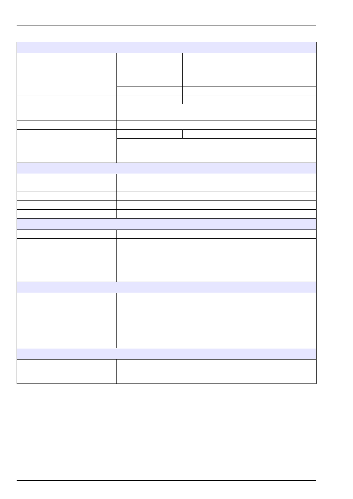
Specifications
Inputs / Outputs
Number 8
Functions 6 threshold alarms / lack of sample / active channel
Alarms
Cut-off power 30 VDC, 0.5 A maximum
Number 12
Logical inputs
Serial input interface RS 485, Modbus communication protocol
Outputs 4 / 20 mA
Materials and protection
Transmitter Aluminium with polyester paint
Panels and other boxes Polystyrene
Protection transmitter box IP 65
Protection cabinet (optional) IP 54
Cabinet front door Plexiglas
Maintenance
Remote alarm clearance
By-pass measurement for a channel
Number 8
4/20 mA or 0/20 mA programmable
Galvanically insulated
Maximum charge of 800 ohms
1 system alarm
1 warning alarms
Calibration Chemical zero, slope with calibration solution
Maintenance
Reagent consumption Approximately 1L per month and per reagent
Calibration solution consumption Approximately 200 ml / calibration
Time safeguard lithium battery CR 1220 (3 V)
Transmitter
Display
Mains power supply
Mains
No particular maintenance is necessary
Cleaning can be done with a soft non-aggressive cloth
Programming by menu
Concentration of 6 samples
Analyzer status
Alarms
Trend curves
Concentration historic
Calibration parameters historic (date, slope and offset)
100 - 240 VAC 50 - 60 Hz
Automatic switching
Max. consumption: 80 VA
12
Page 15
Section 3 Analyzer Overview
3.1 Operation
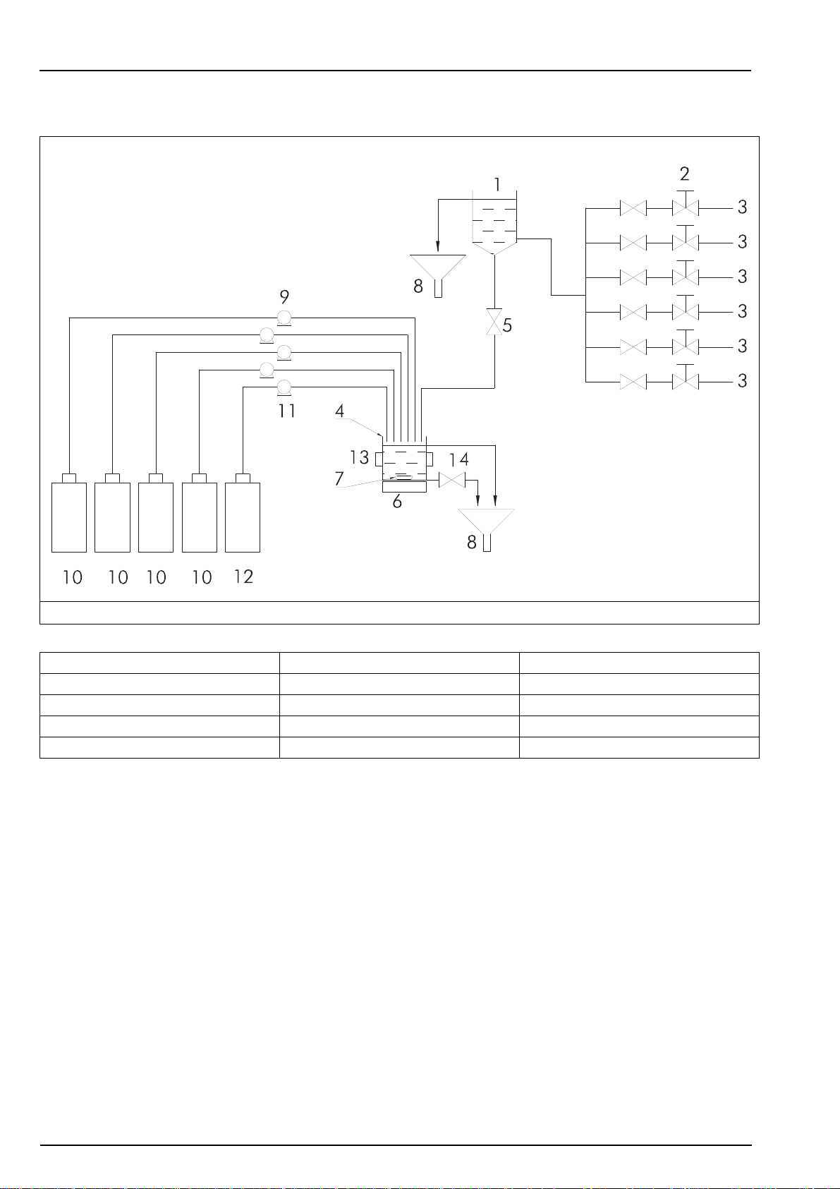
Figure 1 Working principal
1 - Overflow tank with level detector 6 - Mixing motor 11 - Calibration pump
2 - Flow adjustment valves (1 to 6) 7 - Magnetic bar 12 - Calibration solution canister
3 - Sample input (1 to 6) 8 - Drain 13 - Photometer
4 - Photometric measuring cell 9 - Reagent pumps (x4) 14 - Drain pump of measuring cell
5 - Measuring solenoid valve 10 - Reagent canisters (x4)
The 9210 can analyze up to six different samples. The sample to be analyzed circulates in a
fast loop permitting rapid renewal of the sample. Adjustment of the flow is carried out with the
help of a needle valve (2). At the beginning of the analysis, the sample is introduced into the
measuring cell (4) with the use of a solenoid valve (5).
The reagents R1M and R1A are first added using two of the reagent pumps (9). The silica
contained in the sample then reacts with the molybdate and forms the silicomolybdic complex.
The reaction will take up to 5 minutes.
Oxalic acid is then added using a reagent pump (9) to avoid phosphate interference and to
intensify the color.
The silicomolybdic complex is reduced to a blue molybdenum complex by means of ferrous
ions. A photometric measurement is carried out at the end of the reaction.
13
Page 16

Analyzer Overview
3.2 Calibration
In order to ensure accurate measurements, the analyzer should be calibrated periodically. The
zero is achieved chemically and internally in the analyzer. The system slope is controlled by
comparison to a standard solution of known concentration. Further information regarding
calibrations can be found in the section entitled Calibration on page 51.
3.3 Analyzer outputs
The instrument can measure silica concentration from three different sources:
• the process sample during a normal measuring cycle
• the calibration solution during an automatic calibration
• an external sample during the grab sample operation
Whatever the sample source, the measurement cycle structure is identical and all analyzer
outputs (e.g. 4/20 mA outputs, screen display, RS485 data, alarm status, etc.) are refreshed
during the last minute of the measurement.
3.4 Maintenance
To ensure a high degree of accuracy is maintained by the analyzer, it is recommended to
perform a specific maintenance procedure once a year. All replacement parts and fittings are
available by purchasing the maintenance kit 09120=A=8000 which contains enough parts and
fittings for two years.
Full details on this procedure and the contents of the maintenance kit can be found in Yearly
maintenance on page 60.
14
Page 17
3.5 Presentation
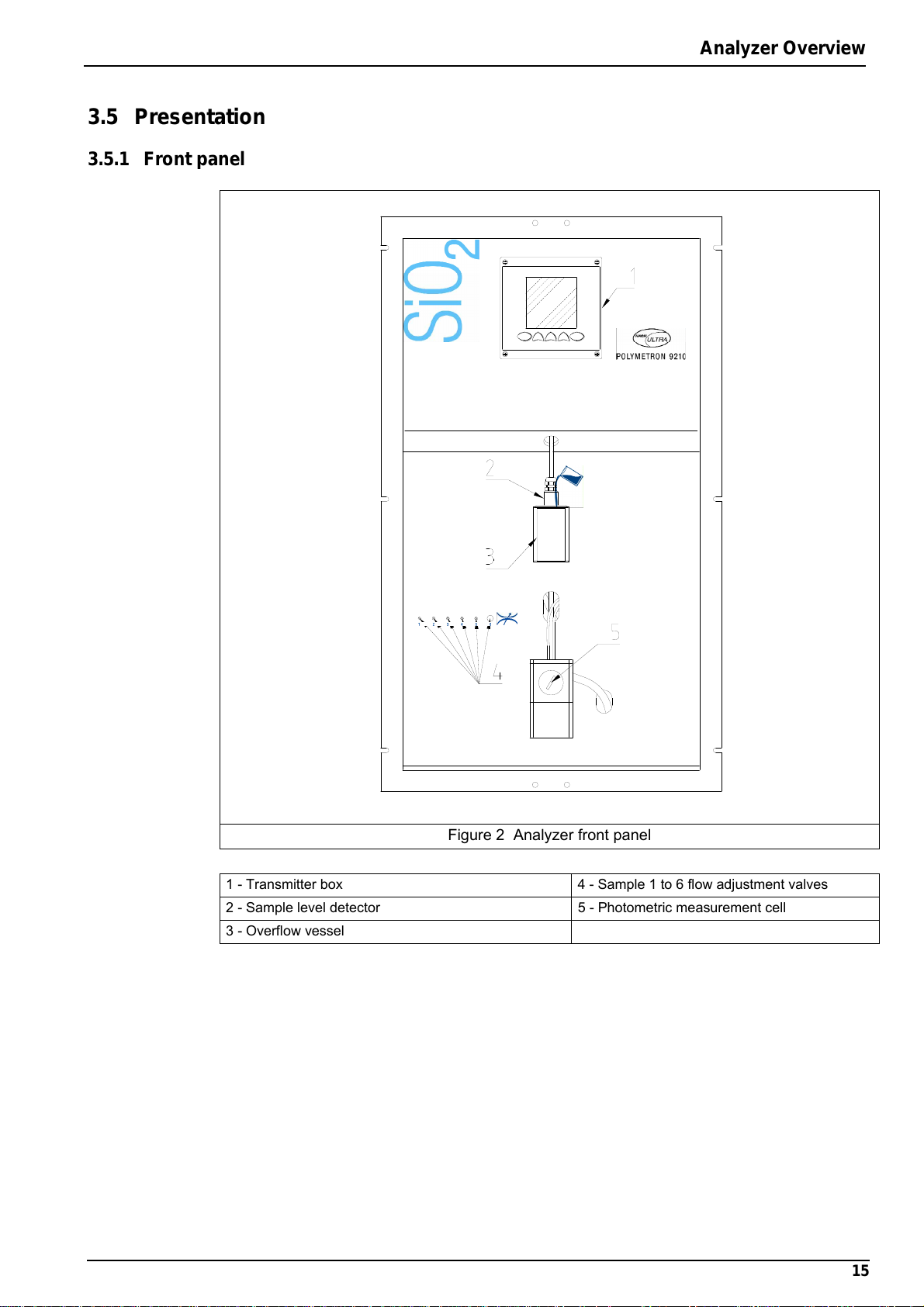
3.5.1 Front panel
Analyzer Overview
Figure 2 Analyzer front panel
1 - Transmitter box 4 - Sample 1 to 6 flow adjustment valves
2 - Sample level detector 5 - Photometric measurement cell
3 - Overflow vessel
15
Page 18
Analyzer Overview
3.5.2 Rear panel
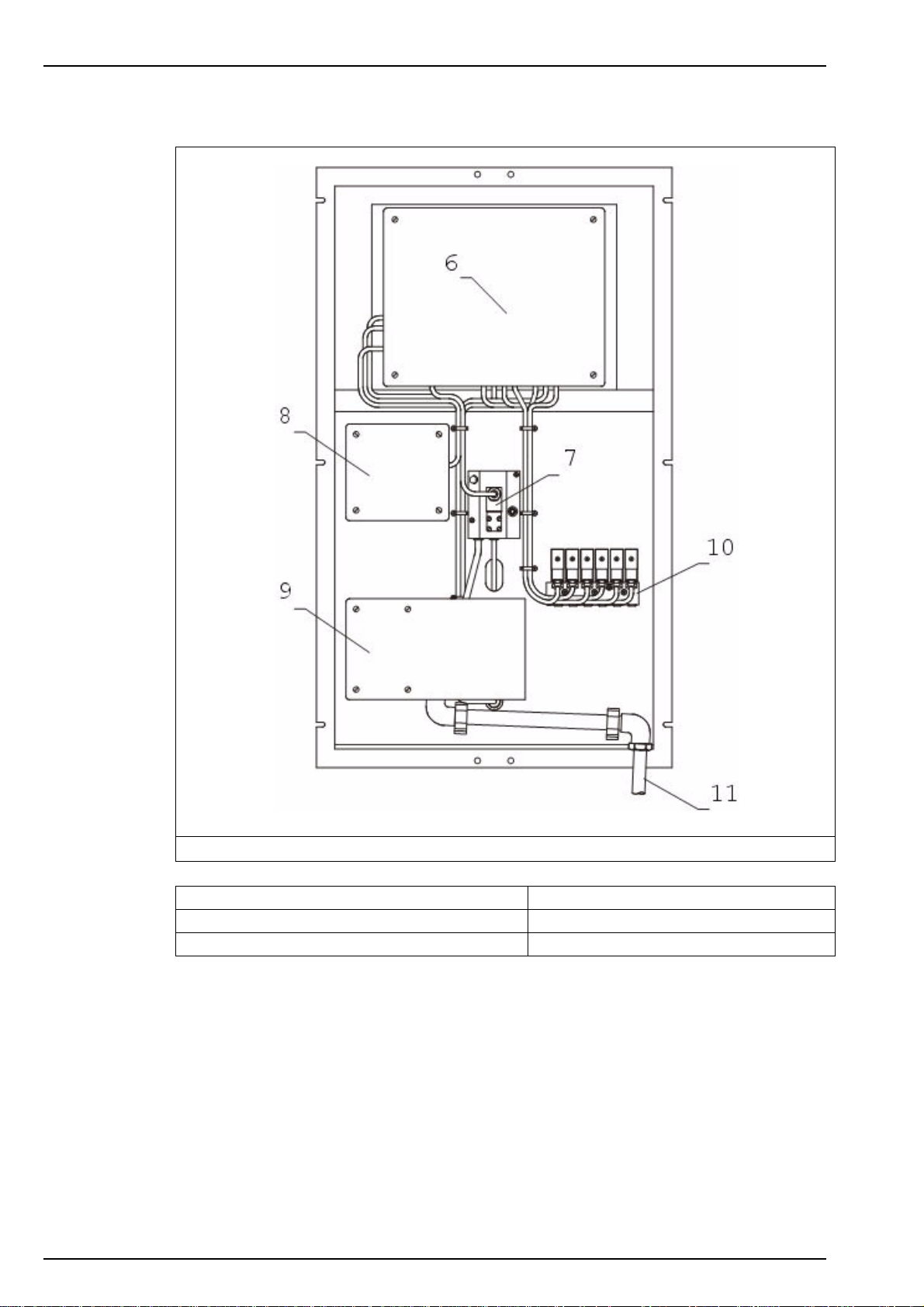
16
Figure 3 Analyzer rear panel
6 - Local controller box 9 - Measurement box
7 - Measurement solenoid valve 10 - Sample inlet valves
8 - Pumps box 11 - Drain
Page 19

Section 4 Installation
WARNING
The analyzer should only be assembled by qualified staff. Mains power should only be
connected once installation has been completed and checked.
4.1 Analyzer inspection and unpacking
The analyzer has been factory tested and checked prior to shipping. We nevertheless
recommend that you perform a visual inspection in order to ensure that it has not been
damaged. Any marked packaging is a potential sign of damage that may not be immediately
visible. Keep all packaging in the event of claims.
Open the box. Take the packing list from the box and check the presence of all the items
selected. If any parts or accessories are missing, refer to your distributor or to Hach Lange.
4.2 Analyzer preparation
Before installing the analyzer, think about the following:
• Place the analyzer close to the sample point. This will allow the response time to be reduced.
• The sample should be homogenous and representative.
• The temperature of the sample should be between 5 and 50°C.
• The pressure of the sample should be between 0.2 and 6 bar and remain relatively stable.
• The solution should be free of particles.
• Sample lines should be in PE/PTFE/FEP (4 x 6 mm).
• Avoid any location with a corrosive atmosphere or subject to liquid spills.
• Chose a dry and dust-free location.
• The ambient temperature of the analyzer should not exceed 45°C. If the temperature is
below 5°C, the analyzer should be installed in a heated cabinet (not provided by Hach
Lange).
4.3 Installation checklist
For a complete installation, perform the following actions in the order specified, following the
instructions very carefully:
1. Mount the analyzer - section 4.4 on page 18
2. Install the canister holder - section 4.5 on page 20
3. Connect the sample lines - section 4.6 on page 21
4. Connect the drain tube - section 4.7 on page 22
5. Connect the mains power - section 4.8 on page 22
6. Connect the external communications - section 4.9 on page 26
7. Input/Output connections - section 4.10 on page 27
8. Reagent preparation - section 4.11 on page 29
9. Connect reagent canisters - section 4.12 on page 31
10. Analyzer stabilization and startup - section 4.13 on page 32
17
Page 20

Installation
4.4 Mounting the analyzer
CAUTION
Wherever the analyzer is to be mounted, it is important to note that it must be placed in
an upright position with the transmitter at the top. It is recommended to use a spirit level
to ensure that the analyzer is correctly positioned and not leaning to one side or forward.
This is essential to guarantee the accuracy of the analyzer.
4.4.1 Panel version
For the panel version, the dimensions of the analyzer and fixation holes are shown in Figure 4.
18
Figure 4 Panel version dimensions - mm [ins]
A. Mains power supply cable gland, drilled ∅ 11 (5 to 10mm), 100…240V, 50-60Hz, 25VA
B. Field bus cable gland, drilled ∅ 13 (6 to 12mm)
C. 5 to 7 mm cable gland
• Alarm signals: 30V, 0.5A max.
• Logic inputs: Cutoff on channels 1 to 6, acknowledgement of alarm signals
• Analog outputs: 0-20 mA or 4-20 mA
D. Sample inlets, (channels 1 to 6), QR coupling for semi-rigid tubing ∅ 6mm, 5 to 50°C
(40° to 120°F), P 0.2 to 6 bar (3 to 87 PSI)
E. Drain tube: silicon tubing ∅ 12 x 17mm, at atmospheric pressure
Page 21
4.4.2 Cabinet version
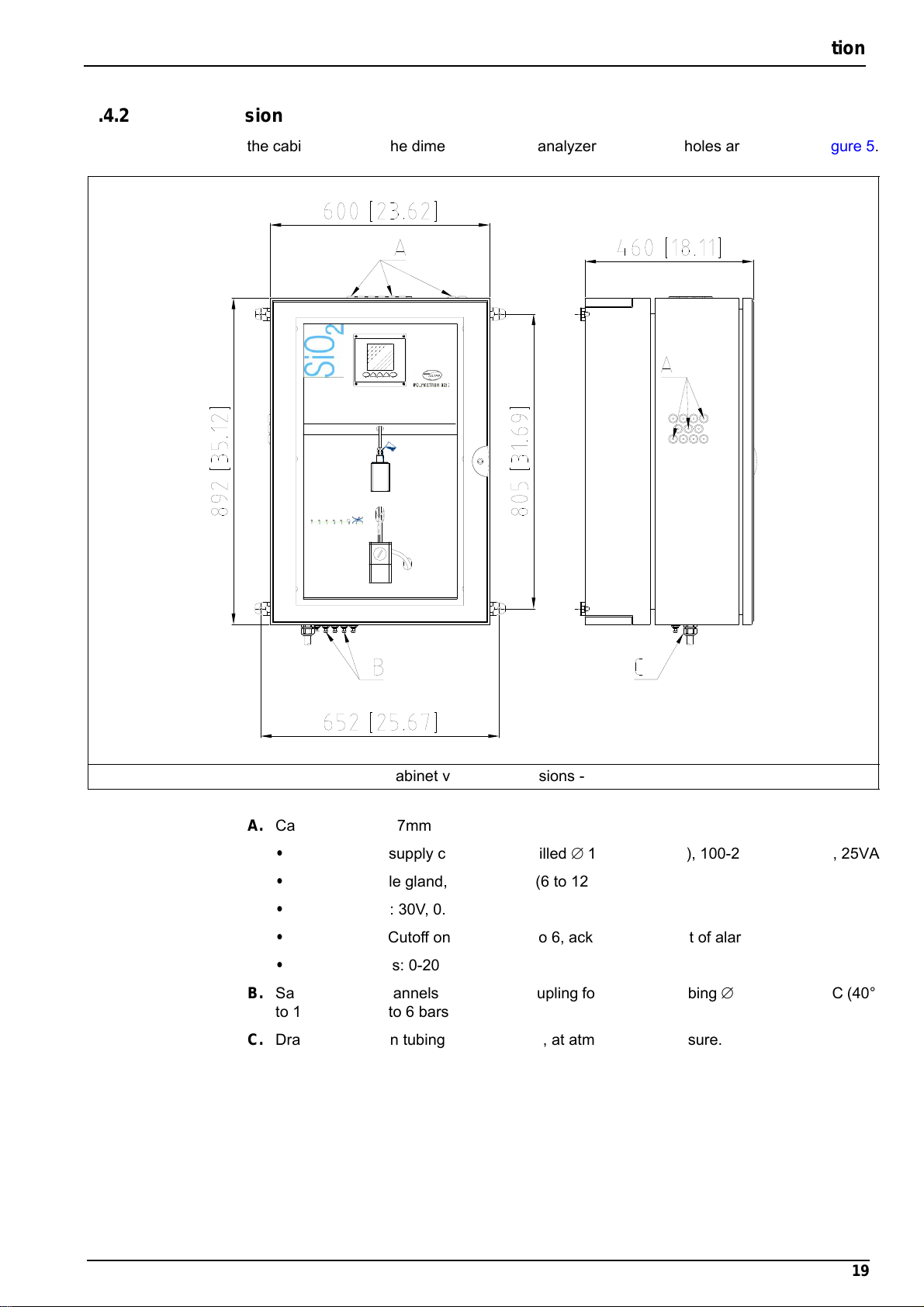
For the cabinet version, the dimensions of the analyzer and fixation holes are shown in Figure 5.
Installation
Figure 5 Cabinet version dimensions - mm [ins]
A. Cable gland, 5 to 7mm
• Mains power supply cable gland, drilled ∅ 11 (5 to 10mm), 100-240V, 50-60Hz, 25VA
• Field bus cable gland, drilled ∅ 13 (6 to 12mm)
• Alarm signals: 30V, 0.5A max.
• Logic inputs: Cutoff on channels 1 to 6, acknowledgement of alarm signals
• Analog outputs: 0-20mA or 4-20mA
B. Sample inlets (channels 1 to 6), QR coupling for semi-rigid tubing ∅ 6mm, 5 to 50°C (40°
to 120°F), P 0.2 to 6 bars (3 to 87 PSI)
C. Drain tube: silicon tubing ∅ 12 x 17mm, at atmospheric pressure.
19
Page 22
Installation
4.5 Installing the canister holder
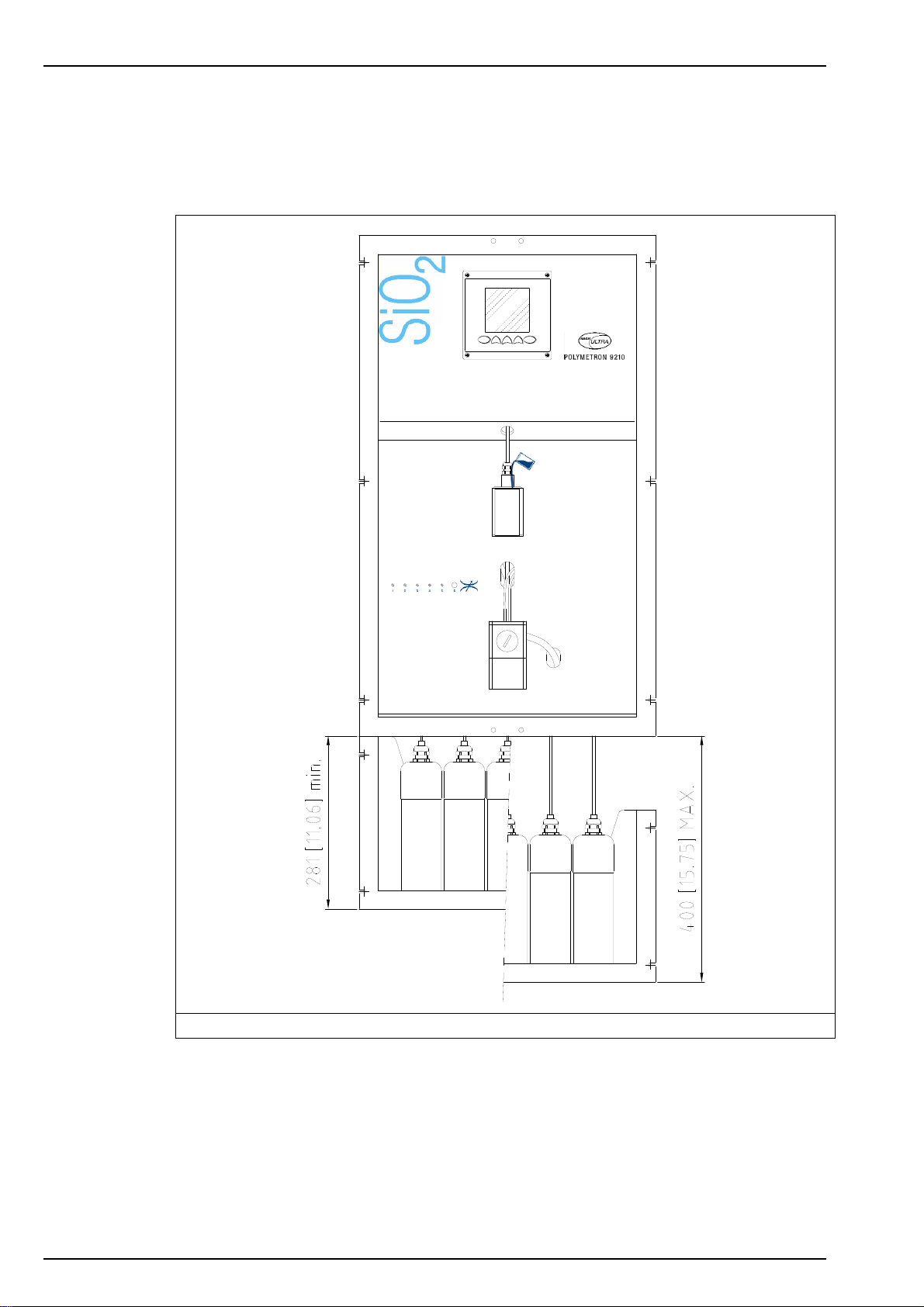
For cabinet versions, a canister holder is pre-mounted in the rear of the cabinet. For the panel
version, a canister holder is supplied separately and must be installed under the analyzer as
illustrated in Figure 6 below.
20
Figure 6 Canister holders
Ensure the position of the canister holder does not exceed the maximum and minimum
distances from the bottom of the analyzer that are given in Figure 6 above.
Page 23
4.6 Connecting the sample
Use new tubes for connections during installation
• Exterior ∅: 6 mm exactly (or ¼'')
• Material: polyethylene or PTFE or FEP
• Pressure: 0.2 to 6 bar
• Temperature: 5 to 50°C
Installation
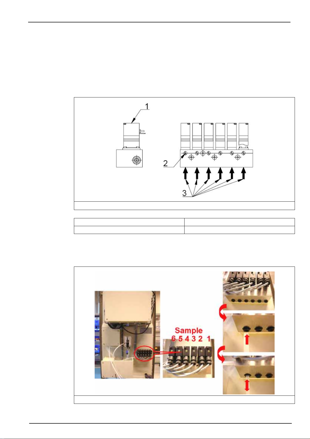
Figure 7 Sample connections schematic
1 - Solenoid valve 3 - Sample input 1 to 6
2 - Solenoid valve flow adjustment screw
At this stage of the installation, make sure that the flow valves (2) are all closed.
Connect the tubes by inserting into the quick release connections found under the sampling
block as illustrated in Figure 8 below.
Figure 8 Sample connections
21
Page 24

Installation
4.7 Connecting the drain tube
The drain outlet is located on the bottom of the analyzer. A 12 x 17 mm pipe is delivered with
the analyzer and should be connected to the drain outlet at one end and the other fed to a drain
for sample evacuation.
Note: Evacuation should be free of any mechanical constraints, and any counter-pressure.
4.8 Mains power connection
WARNING
No intervention should be carried out on the analyzer without first switching off the
power.
The electrical installation should be carried out by duly qualified personnel. A supply voltage of
100-240 VAC is acceptable without changing the configuration. The power supply terminals can
be removed from their housing to make connection easier.
For safety reasons, it is imperative to respect the following:
• Use a three-wire power lead (live + neutral + earth) for supplying the required power.
• The analyzer should be connected to the mains via a circuit-breaker or fuse whose value
should be less or equal to 20 A. It should be located in the proximity and be identified.
This connection should cut-off the live and neutral when electrical problems occur or
when the user wishes to intervene inside the analyzer. However, the earth conductor
should always be connected.
Figure 9 Drain connection
22
Page 25

Installation
The following procedure outlines the steps required to connect power to the analyzer. The main
cabinet should be open with access to the interior:
1. Open the transmitter front
door by unscrewing the
four holding screws.
2. Swing open the door (it is
hinged to the left) to
reveal the inside of the
transmitter.
3. Remove the metallic
shielding plate protecting
access to the main board.
4. Once the shielding plate
is removed, the location
of the power cable gland
can be seen (indicated
with the arrow).
23
Page 26

Installation
5. Next, run the power
supply cable through one
of the external cable
glands located on the left
outside of the cabinet (A),
and into the analyzer.
6. Put your hand behind the
local controller box and
you will locate two cable
glands to the left and two
to the right on the bottom
of the transmitter (B). The
cable gland for the power
cable is located left and
nearest to you.
7. Unscrew the cable gland
nut, pass the power cable
through it, and then up
through the cable gland
and into the transmitter.
8. Screw back the cable
gland nut to secure the
power cable.
9. Remove the power supply
connector and note where
the earth, live and neutral
must be connected.
24
Page 27
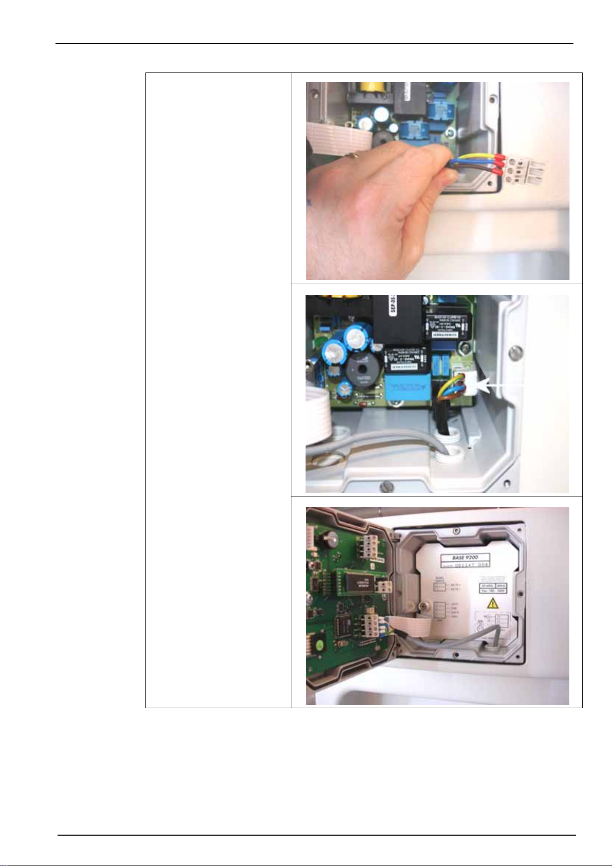
10. Connect the power supply
cables to the connector.
Installation
11. Put the connector back in
place.
12. Replace the metallic
shielding plate, ensuring it
is in front of the power
cable just installed.
25
Page 28
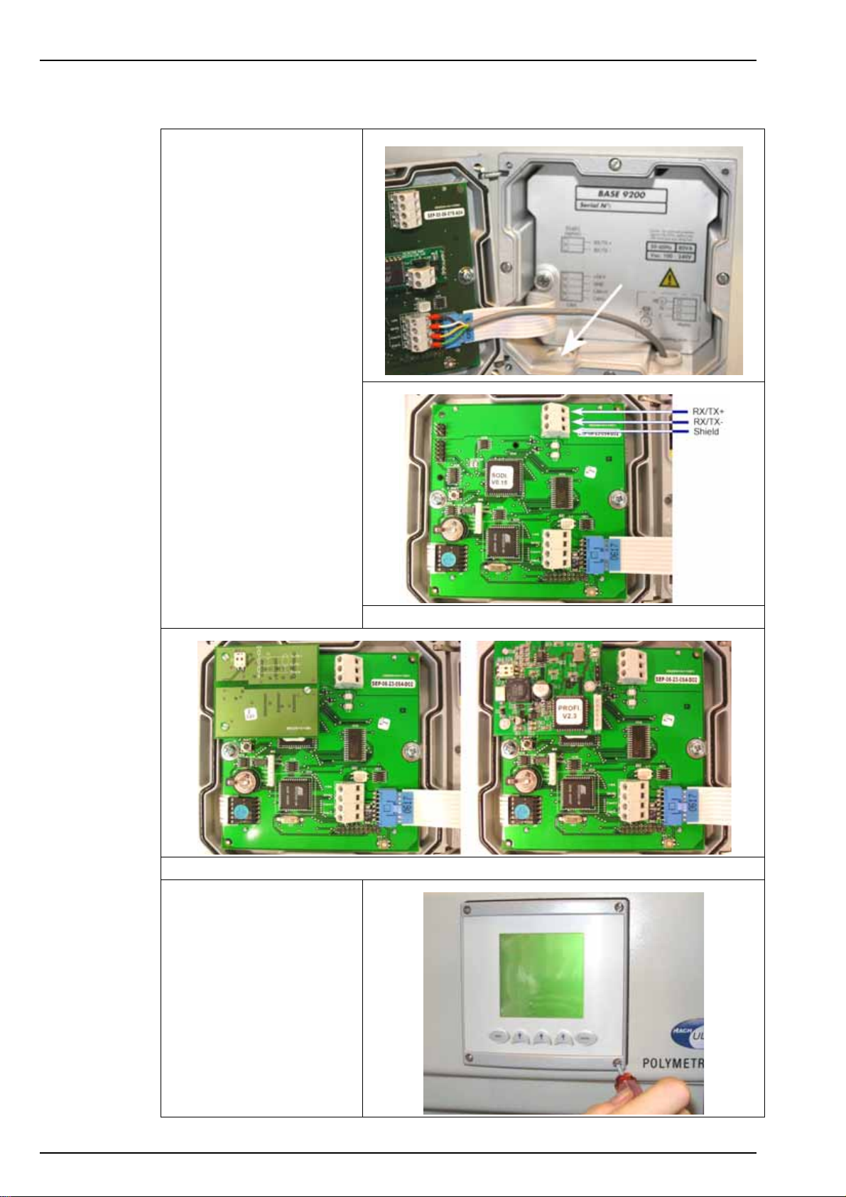
Installation
4.9 External communications connection
1. As with the power cable,
run the communications
cable through an external
cable gland on the left
side of the cabinet, and
into the analyzer.
2. Pass it through the cable
gland located right and
farthest from you on the
base of the transmitter, so
it appears inside the
transmitter through the
left front cable gland (as
indicated).
3. Depending on the type of
board installed in the
analyzer, connect the
communication cable as
indicated.
Note: Connection is the same on
the CPU board for both the
JBUS/MODBUS and PROFIBUS
options.
CPU board without RS485 option
CPU board with JBUS/MODBUS option - - - - - CPU board with PROFIBUS option
26
4. Close the transmitter door
and screw securely back
in place.
Page 29
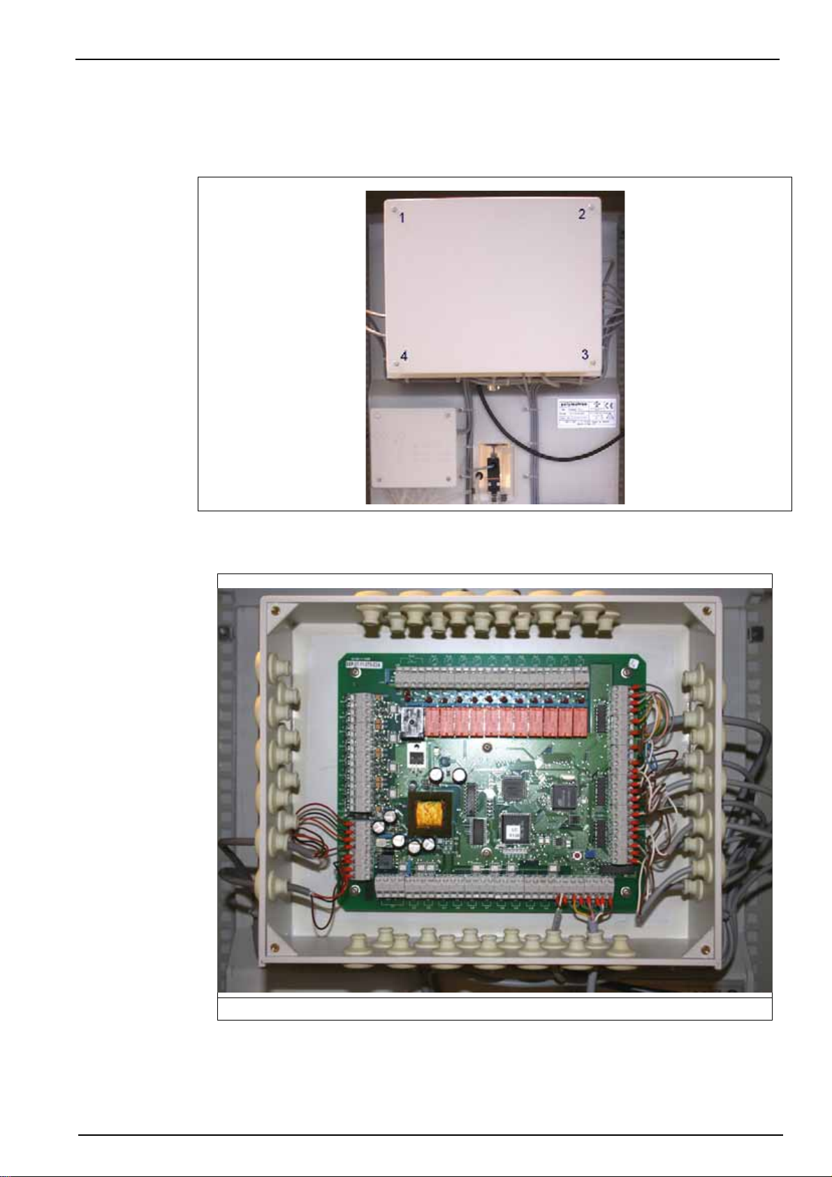
4.10Input/Output connections
To gain access to the I/O connections, open the back of the local controller box by unscrewing
the 4 corner screws.
Installation
This will reveal the I/O board as illustrated in Figure 10 (which shows connections already in
place).
Figure 10 Local controller connections
27
Page 30
Installation
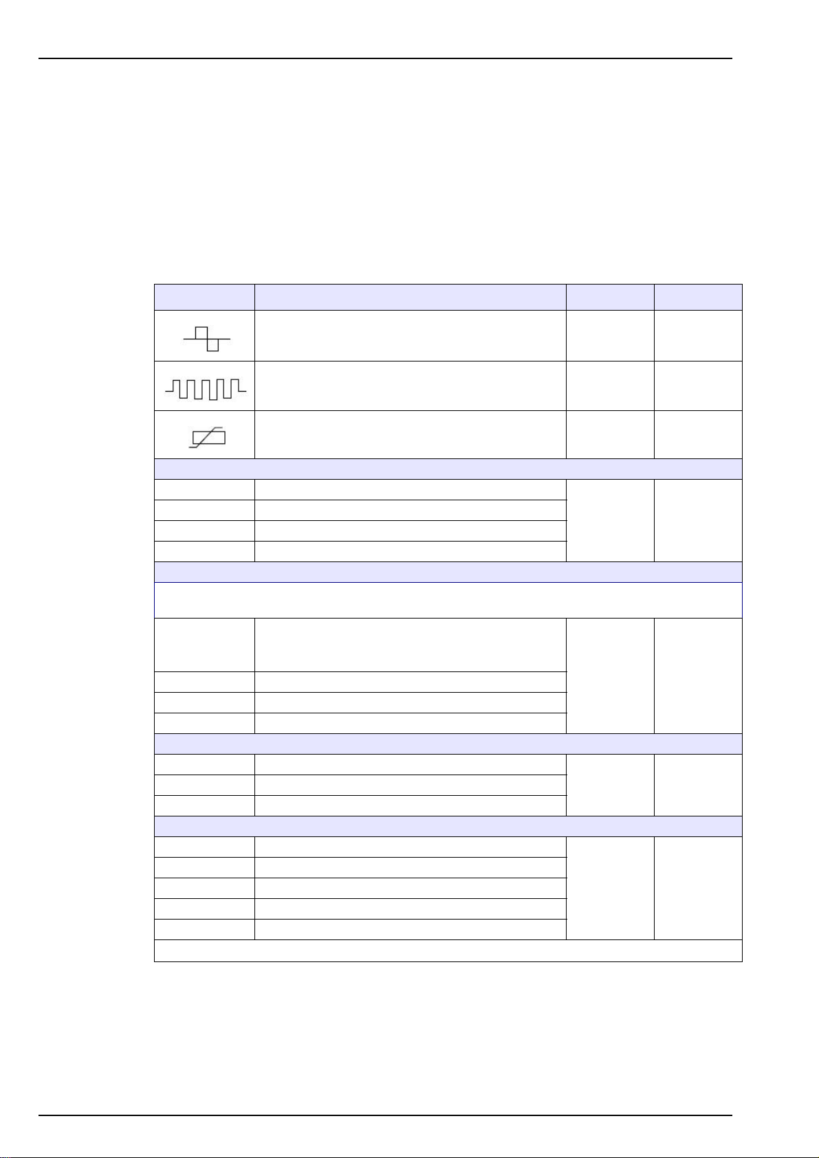
Before using any of the cable glands, perforate first with a screwdriver. To ensure a good seal,
the external diameter of the cables should be between 5 and 7 mm.
For information on the connections available refer to Table 1.
CAUTION
The relay outputs can only supply power in very low safety voltage (30 VAC or 42.4 VDC
maximum) and limited to 0.5 A.
The nomenclature given in the connections column of Table 1 below, refers to the same
nomenclature that is printed on the I/O board against each available connection.
Connections Function Max. voltage Max. current
Mixer control 24 VAC 1 A
Heater control 24 VDC 1 A
Cell temperature measurement 5 VDC 1 mA
Re1 to Re6 User relay of thresholds 1 - 6
Re7 to Re10 Not used
Re11 Warning alarm
Re12 System alarm (NO and NC switches are available)
Note: Dry relays are used for all the following logical inputs. At best, provide 1 dry circuit (no voltage)
which will be closed to launch an action.
By-pass sample measurement (channels 1 - 6)
In1 to In6
In7 to In10 Not used
In11 Remote acknowledgment of alarms
In12 Level sample detector
Iout1 to Iout6 Analog output 0-20 or 4-20 mA (channels 1 - 6)
Iout8 Not used
Vout1 Sample electrovalve control
Vout2 to Vout7 Sample selection electrovalve controls (channels 1 - 6)
Vout8 Calibration pump
Vout9 to Vout11 Reagent pumps
Vout12 Drain pump
For input In1, use terminals " in " and " - "
Terminals " + " and " out " are not used
30 Veff or
42.4 VDC
5 VDC 5 mA
24 VDC 23 mAIout7 Analyzer status
30 VDC 1 A
0.5 A
resistive
charge
Table 1 Relay functions
28
When all I/O connections have been made, put the cover back on the local controller box and
secure in place with the 4 screws.
Page 31
4.11 Reagent preparation
The four reagent solutions, and the calibration solution should be prepared as per the following
instructions. Before refilling the five canisters with 2 liters of their respective solution, they
should be thoroughly rinsed with ultra pure water.
Note: These solutions are best prepared with the aid of a magnetic stirrer.
WARNING
Read the Material Safety Data Sheets (MSDS) on page 77 and wear protective goggles
and clothes before using chemical products.
4.11.1 Reagent 1M - Molybdate (2 liters)
Label Composition Concentration
R1M Sodium dihydrate molybdate Na
(analytical quality; Fluka# 71756, Merck# 106521 or equivalent)
• Rinse a 2 liter volumetric flask three times with ultra pure water
MoO4.2H2O >99%, neat
2
Installation
55 g/L
• Fill two-thirds of the flask with ultra pure water which has less than 5 ppb of SiO
• Stirring continuously for about 5 minutes, gently dissolve 110g of the sodium dihydrate
molybdate in the water. The turbidity of the solution should be very low
• Top up the solution to 2 liters with additional ultra pure water, and transfer the solution to
the canister labelled R1M
4.11.2 Reagent 1A - Nitric acid (2 liters)
Label Composition Concentration
R1A Nitric Acid, HNO
equivalent)
(65% Puriss analytical grade; Fluka# 84380 or
3
• Rinse a 2 liter volumetric flask three times with ultra pure water
• Fill two-thirds of the flask with ultra pure water which has less than 5 ppb of SiO
• Stirring continuously for about 5 minutes, gently pour 300mL of nitric acid into the water.
The solution should be clear
• Top up the solution to 2 liters with additional ultra pure water, and transfer the solution to
the canister labelled R1A
4.11.3 Reagent 2 - Oxalic acid
2
150 mL/L, 15% V/V
2
Label Composition Concentration
R2 Oxalic Acid (Puriss analytical grade; Fluka# 75700 or equivalent) 40 g/L
• Rinse a 2 liter volumetric flask three times with ultra pure water
• Fill two-thirds of the flask with ultra pure water which has less than 5 ppb of SiO
2
• Stirring continuously for about 5 minutes, gently dissolve 80g of oxalic acid in the water
• Top up the solution to 2 liters with additional ultra pure water, and transfer the solution to
the canister labelled R2
29
Page 32
Installation
4.1 1 .4 Reagent 3 - Reducing reagent
Label Composition Concentration
R3 Ammonium-iron(II) sulfate hexahydrate (NH
(Puriss analytical grade; Fluka# 09720, Merck# 103792 or equivalent)
Sulfuric acid (H
2SO4
• Rinse a 2 liter volumetric flask three times with ultra pure water
• Fill two-thirds of the flask with ultra pure water which has less than 5 ppb of SiO
• Stirring continuously, gently pour 25mL of sulfuric acid into the water
• Stirring continuously, gently add 40g of ammonium-iron(II) sulfate hexahydrate to the
solution
• Top up the solution to 2 liters with additional ultra pure water, and transfer the solution to
the canister labelled R3
4.11.5 Calibration solution
CONCENTRATED SOLUTION
Use of Titrisol® (Merck) cartridge
Fe(SO4)2, 6H2O
4)2
) (95-97%; Fluka# 84721 or equivalent) 12.5 mL/L
20 g/L
2
Dilute one cartridge of Titrisol® Merck 109947 solution with one liter of demineralized water to
give a concentration of 1000 mg/liter of Si, i.e. 2139 mg/liter of SiO
times, i.e. 10 mL per liter to give a concentration of 10 mg/liter of Si, i.e. 21.39 mg/liter SiO
. Dilute this solution 100
2
.
2
CALIBRATION SOLUTION
By diluting the concentrated solution (at 21.39 mg/liters) with demineralized water, various
calibration solutions with a known concentration of SiO
may be prepared. The following table
2
gives the nominal values when using demineralized water having a zero concentration of silica:
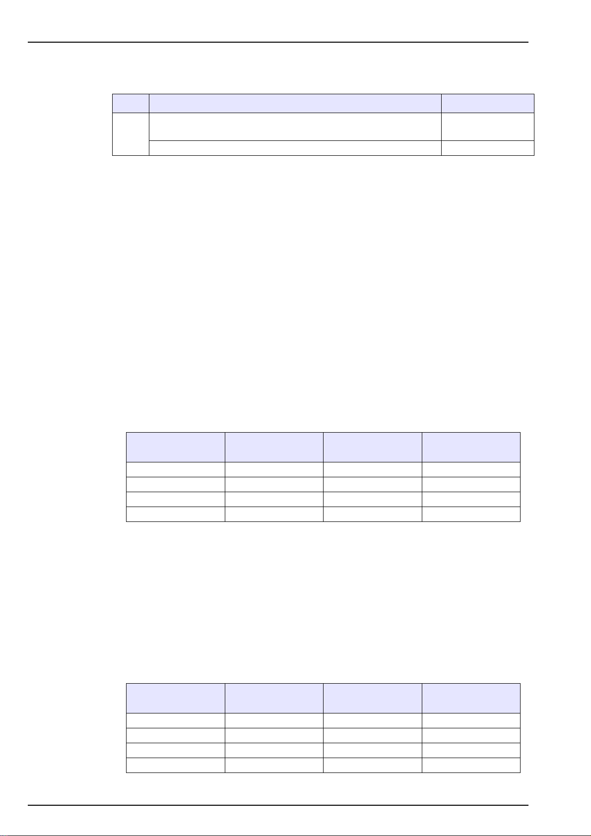
mL of concentrated
solution 21.39 mg/l
10 50 107 0-200 ppb
20 100 213.9 0-200 ppb
25 125 267.4 0-500 ppb
50 250 534.8 0-1000 ppb
Calibration solution
ppb Si
Calibration solution
ppb SiO
2
Analyzer measuring
range
Given that the demineralized water may often have a non-zero silica content, use of one two
methods for determining the nominal silica values of the final calibration solution. On
completion, transfer 2 liters of the solution to the calibration canister labelled CAL.
Note: It is recommended to use demineralized water with a silica content of no more than 5 ppb when
diluting the concentrated solution.
Method 1:
Determine the silica content of the demineralized water by using a laboratory measurement
technique (e.g. Hach Lange laboratory photometer), or by using the grab sample mode of an
accurately calibrated POLYMETRON 9210 if available on site. The concentration value can then
be added to the values in the above table, giving the following revised table when (for example)
using demineralized water with a silica content of 5 ppb (which equates to 2.33 ppb Si):
30
mL of concentrated
solution 21.39 mg/l
10 52.3 112 0-200 ppb
20 102.3 218.9 0-200 ppb
25 127.3 272.4 0-500 ppb
50 252.3 539.8 0-1000 ppb
Calibration solution
ppb Si
Calibration solution
ppb SiO
2
Analyzer measuring
range
Page 33
Method 2:
Prepare the final calibration solution by diluting the concentrated solution (at 21.39 mg/liters)
with demineralized water. Then determine the exact silica concentration value of this solution by
using a laboratory measurement technique (e.g. Hach Lange laboratory photometer) or by using
the grab sample mode of an accurately calibrated POLYMETRON 9210 if available on site.
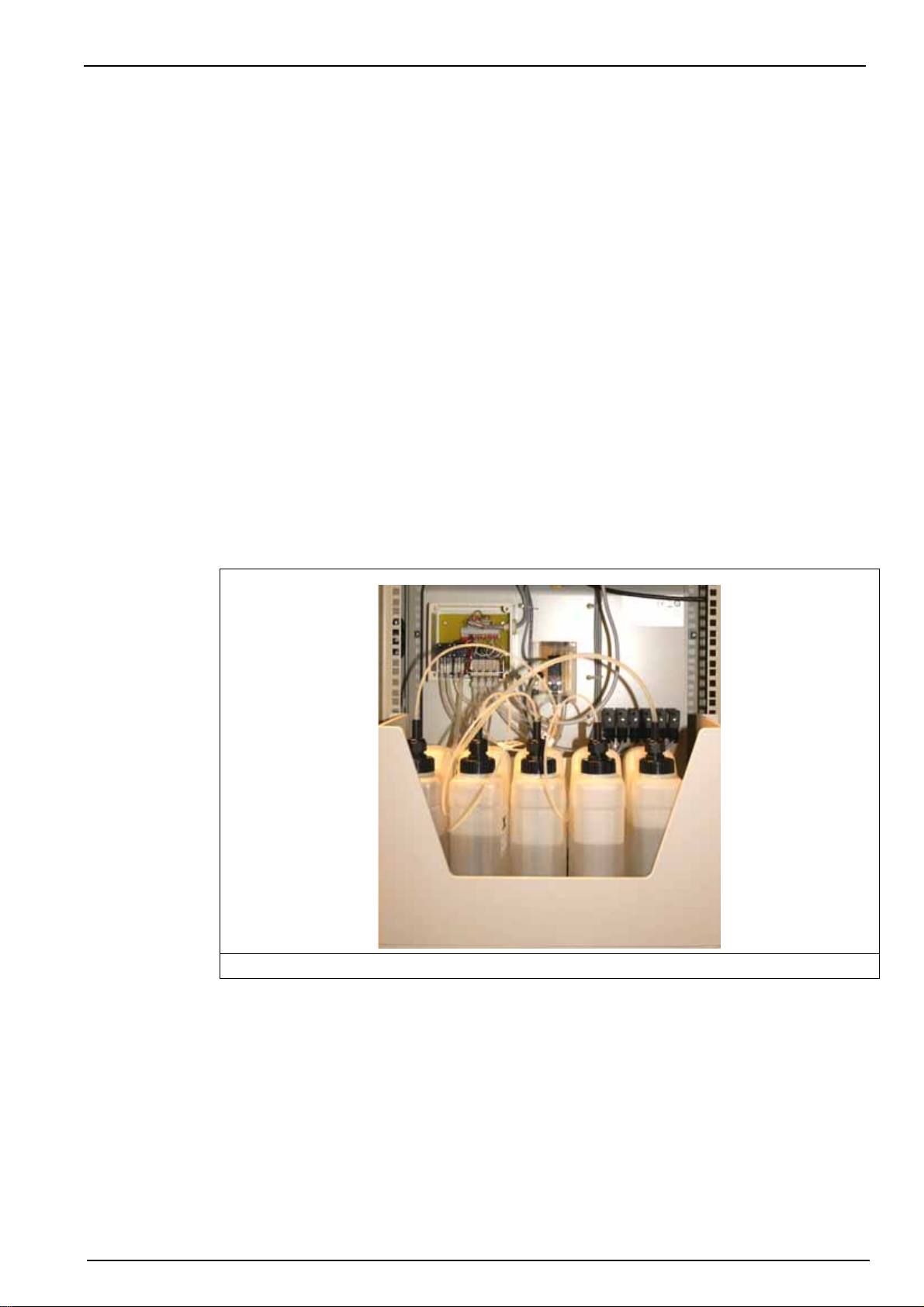
4.12 Connecting the canisters
Each reagent tubing is labelled individually and delivered already connected to the analyzer.
They are fed through, and attached to, caps that attach to the reagent canisters. One end of the
tube is fitted with a chemically inert PVC weight that is used to position the tube in the bottom of
the canister.
Connect each cap to its canister:
• Tube R1M to reagent canister labelled R1M: Sodium molybdate
• Tube R1A on reagent canister labelled R1A: Nitric acid
• Tube R2 on reagent canister labelled R2: Oxalic acid
• Tube R3 on reagent canister labelled R3: Sulfuric acid and ferrous ammonium sulfate
Installation
Screw the cap on each canister so that the weight is resting at the bottom of the canister. Put
the canister in the canister holder with the cap towards the exterior as shown in Figure 11
below.
Figure 11 Canisters connected
The canister on the far right of the illustration is the calibration solution. This has a thicker tube
compared to the reagents. Ensure that the cap has also been securely screwed on to this
canister.
At this stage, the analyzer doors can now be closed and locked as access to the interior of the
analyzer is no longer required.
31
Page 34

Installation
4.13 Analyzer startup
At this stage the analyzer has been completely installed. However, you will be required to enter
data using the display panel functions to make the analyzer operational. Therefore, in order to
familiarize yourself with data entry procedures, it is advisable to read the section entitled
Operating Instructions on page 33 before continuing.
Once you are familiar with data entry procedures, connect the analyzer to the mains power
supply. Introductory screens will initially be displayed for about 60 seconds, before the main
measurement screen is displayed.
4.13.1 Reagents volume declaration
The reagent and calibration solution canisters have been filled with 2 liters of solution. The
analyzer must be set up to reflect this.
Select the Menu option from the display and select the MAINTENANCE option from the display,
followed by the REAGENTS REFILL option. Set the BOTTLES FULL parameter to Yes. An
example of this screen is shown in section 9.8 on page 64. You can also check that the values
have been set to 2 liters by selecting the ADJUST VOLUMES option.
4.13.2 Flow rate adjustment
Next, the flow rates for each measurement channel must be set. When the sample tubes were
connected, the flow valves were all closed (see section 4.6 on page 21). They must now be
opened to allow sample to flow and be measured. To do this select the STARTUP option from
the MAINTENANCE menu and follow the instructions described in section 9.7 on page 64.
4.13.3 System and user setup procedures
At this point, the analyzer has been completely installed and can begin sample measurement.
To do this, use the Esc function key to exit from the MAINTENANCE menu until you return to
the measurement display screen. Press the Start function key to start the measurement
process. The analyzer must be left to run for a period of two hours in order to stabilize.
During this stabilization period, you can setup the analyzer by first entering system data (see
System Setup on page 37) and user data (see User Setup on page 41).
Once the system and user data has been input and the two hour period of stabilization has
elapsed, the analyzer will need to be calibrated. Follow the procedures in Calibration on
page 51.
The analyzer should now be ready for use. If any problem should arise, please refer initially to
Troubleshooting on page 69. If the problem cannot be overcome, please contact your Hach
Lange representative who will be happy to help.
32
Page 35
Section 5 Operating Instructions
5.1 Data Entry
5.1.1 Function Keys
The display panel of the 9210 has 5 function keys (illustrated below) to allow menu option
selection, field selection, and data entry options.
Figure 12 Function Keys
• The Esc key cancels data input or goes back to the previous screen.
• The Enter key validates the input and goes on to the next step.
• The Up Arrow keys select the option displayed immediately above them on the screen.
5.1.2 Modification of a value
The highlighted digit may be modified with the key. Each digit can then be modified by
pressing the Enter function key. Repeat for each digit.
• On the first digit: possible to enter the " - " sign
• On the other digits: possible to enter a decimal point
Note: If you do not use the keyboard for at least 10 minutes, the analyzer returns to the measure mode
except during the calibration and maintenance options. An access code may be required for the calibration,
programming and service menus (see Code on page 38).
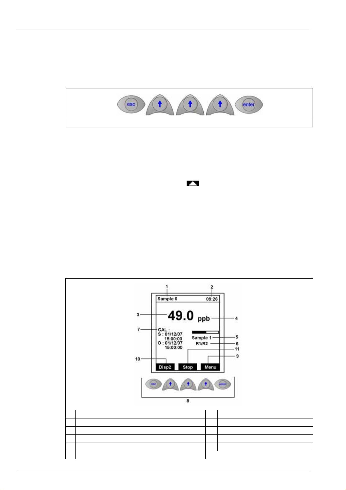
5.2 Measurement screens
5.2.1 Main screen
1. Name of last measured sample 7. Display of the last calibration data
2. Current time 8. Function keys
3. Concentration of last measured sample 9. Access to the main menu
4. Concentration units 10. Go to display 2
5. Sample being analyzed (bar graph indicates progress) 11. Start or stop the measurement
6. Measurement activity
33
Page 36
Operating Instructions
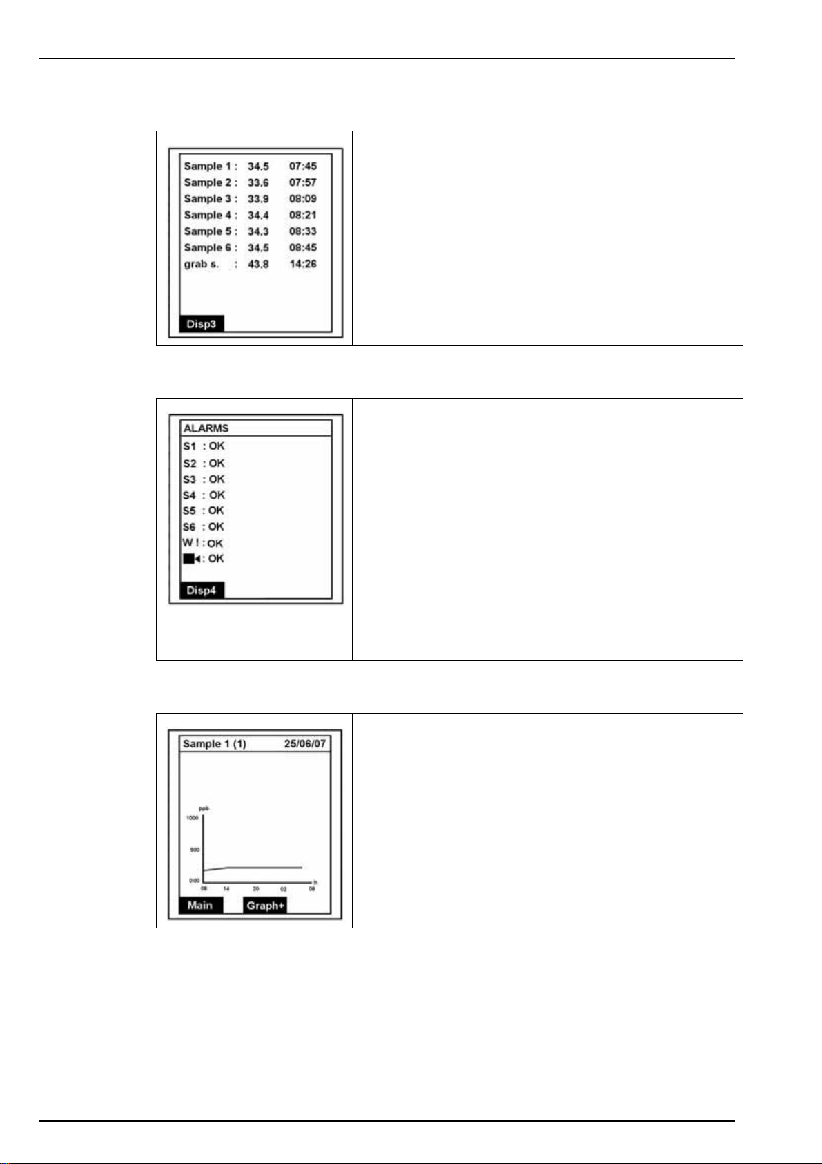
5.2.2 Display screen 2 - Measurement history
Displays a list of the last measurements (sample name,
concentration and time the measurement was taken).
Disp3 takes you to the next display screen.
5.2.3 Display screen 3 - Alarms
Alarms S1-S6 relate to the six alarm outputs which are
followed by the warning and system alarms.
5.2.4 Display screen 4 - Graph
The message against each alarm will indicate the status:
•OK to indicate no problems
• an appropriate error message
• or DISABLE to indicate the alarm has been disabled (this
only applies to the warning and system alarms)
If a manual alarm has been set, press Enter to acknowledge
and deactivate the alarm.
Refer to Alarm conditions on page 46 for a list of possible
error messages.
Disp4 takes you to the next display screen.
This screen shows the measurement trend over a 24 hour
period. The concentration scale is the same as defined by the
analog output scale low and upper values (see Affect on
page 47).
The sample name and associated analog output (in brackets)
is displayed along the top.
34
To display the graph for the next sample, press Graph+ or
press Main to return to the main measurement screen.
Page 37
5.3 Main menu
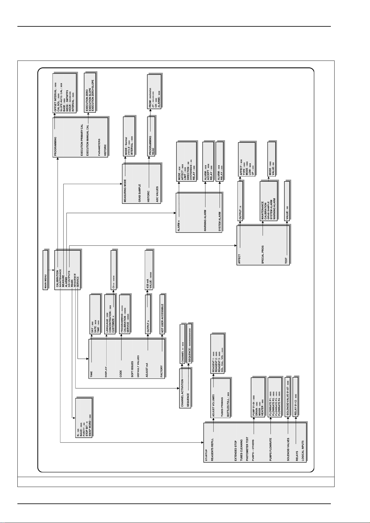
For a diagrammatic overview of the complete menu structure, refer to Analyzer menu overview
on page 36.
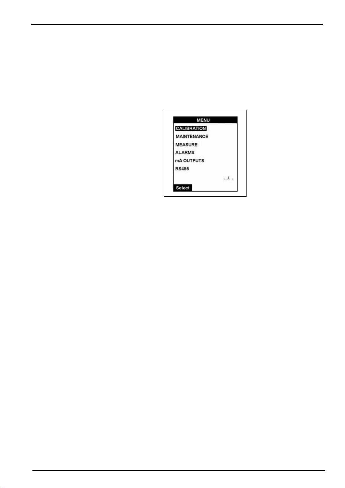
The main menu is accessible from the main measurement screen (see illustration in Main
screen on page 33). Press the function key under Menu to take you to the main menu.
Note: If a PROGRAMMING password has been set (see Code on page 38 for details on how to do this),
you will be required to enter a password to gain access to the main menu.
Operating Instructions
In the illustration above, the symbol “.../...” is displayed in the bottom right. This indicates that
there are more options available in this menu than those currently displayed. As you scroll down
the other menu options will become visible in a rolling menu.
The first option in the menu will always be highlighted by default. To scroll to the required option,
press the Up Arrow function key under the Select option.
Note: Scrolling past the last item in the list will take you back to the first item. It is not possible to scroll
upwards through any list.
Detailed information on all the menu options is available throughout in this manual.
35
Page 38
Operating Instructions
5.4 Analyzer menu overview
36
Figure 13 Analyzer menu overview
Page 39
Section 6 System Setup
Before attempting to setup the analyzer, ensure you have read and understood how to enter
and change data fields as described in the section entitled Data Entry on page 33.
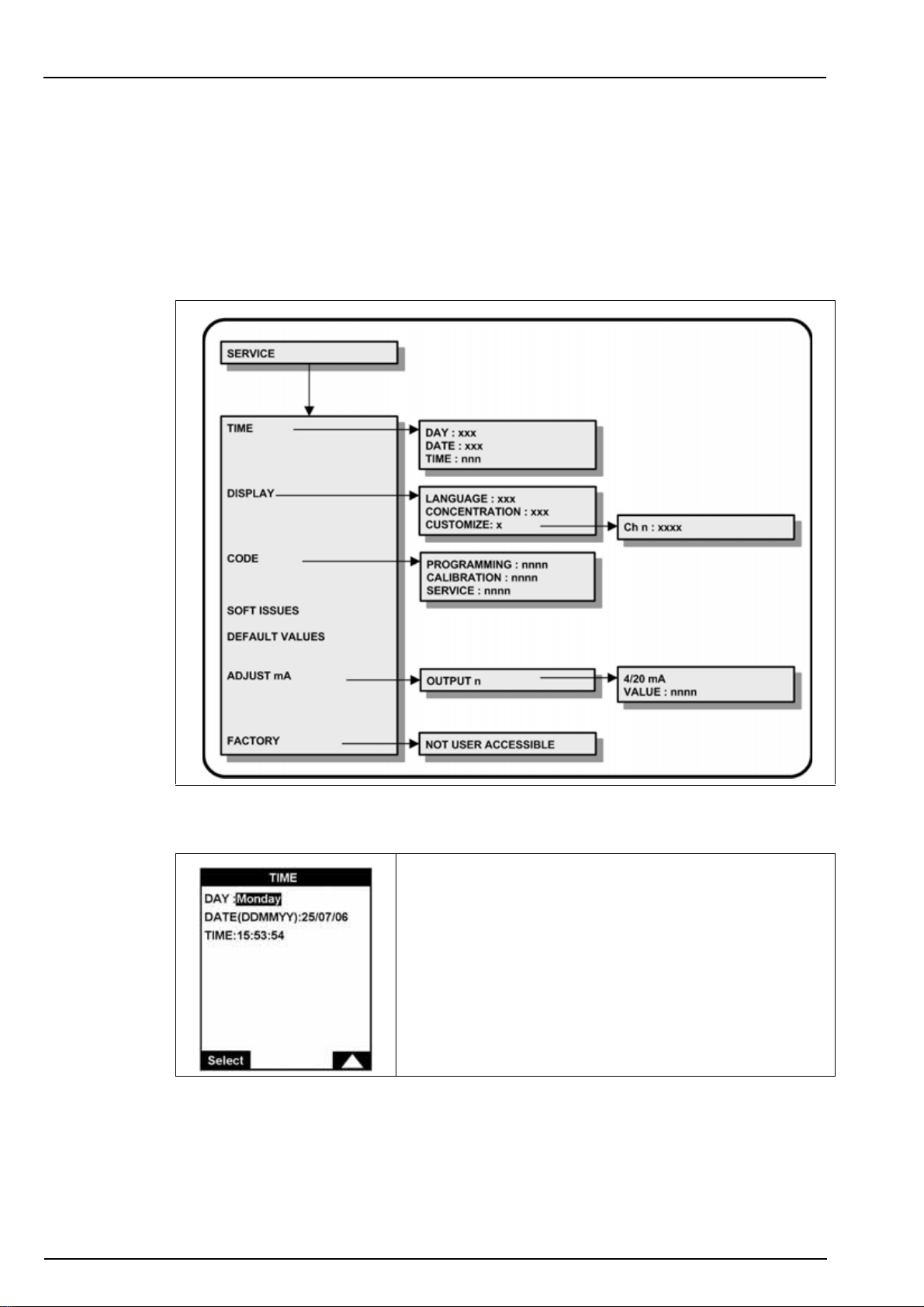
6.1 Menu overview
Select the SERVICE option from the main menu.
Note: If a PROGRAMMING password has been set (see Code on page 38 for details on how to do this),
you will be required to enter a password to gain access to the main menu. In addition, if a SERVICE
password has been set, you will also be required to enter this password to get access to the service menu.
6.1.1 Time
Set the date and the time for the analyzer.
37
Page 40
System Setup
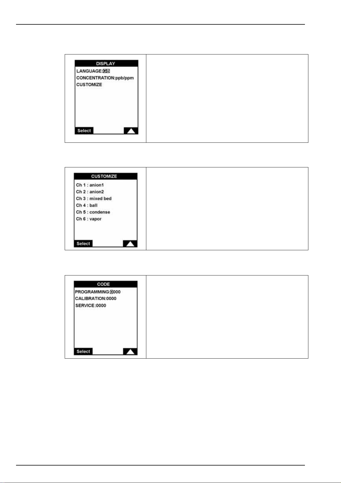
6.1.2 Display
6.1.2.1 Customize
Define the language, concentration units and customize the
channel displays.
Languages: choice of the message language
• French: F
• English: GB
• German: D
• Spanish: Sp
• Italian: I
The unit choice is ppb/ppm, or µg/mg/l
6.1.3 Code
Define each channel with a descriptive name.
You can use lower-case letters, upper-case letters, numbers,
and punctuation signs.
Use this option to enter the codes (passwords) required to
access the analyzer menus. These codes are independent of
one another and can have the same value.
0000 indicates that no access code is required.
38
Page 41
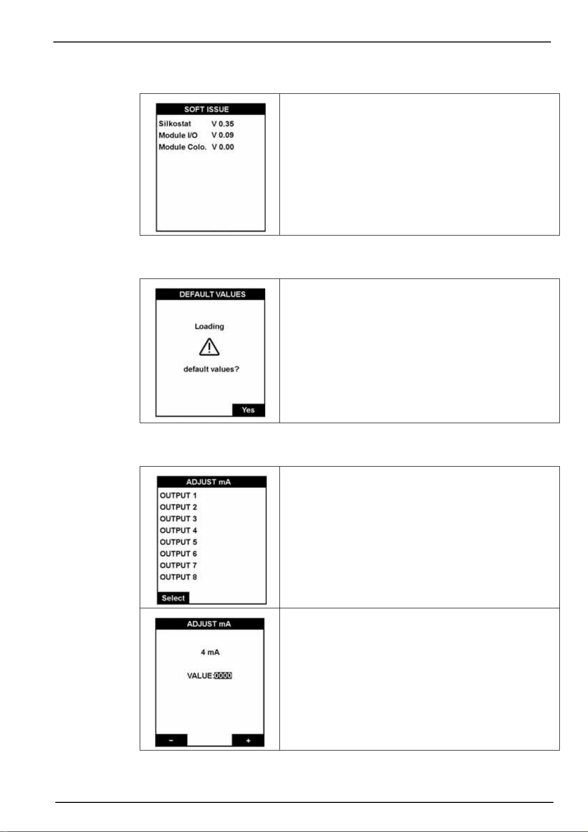
6.1.4 Soft issues
6.1.5 Default values
System Setup
This option displays the version number of the software
installed on the analyzer.
This option allows you to reload all the factory set default
values (see Default Configuration on page 73 for a complete
listing).
6.1.6 mA adjustments
Important Note: This operation will erase all the parameters
(calibration, 4-20 mA scale, alarms, sequence, etc.), and the
default values will be loaded. In addition all measurement
values and alarm history will also be erased.
To exit the screen without loading default values, press Esc.
Each 4-20 mA output can be individually calibrated on a two
point basis.
Connect a milliammeter to each of the 8 outputs in turn.
Use the " - " and " + " keys to make minor adjustments to the
values on the 4 mA outputs.
Validate (press Enter) will move you to the 20 mA outputs
screen.
Adjust the 20 mA value in the same way and then press Enter
to complete the adjustment process and return to the screen
to select the next output to adjust.
39
Page 42

System Setup
6.1.7 Factory
This option is reserved for qualified Hach Lange service
personnel.
If you believe that changes to the factory defined settings may
be required, please contact your local Hach Lange
representative.
40
Page 43
Section 7 User Setup
Before attempting to setup the analyzer, ensure you have read and understood how to enter
and change data fields as described in the section entitled Data Entry on page 33.
The user setup process consists of accessing five sub-menus from the main menu:
• MEASURE
• ALARMS
• mA OUTPUTS
•RS485
• SEQUENCE
7.1 Measure menu overview
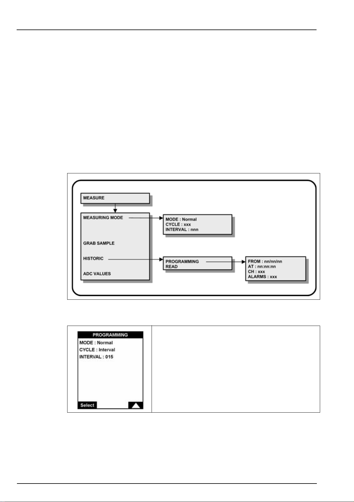
Select the MEASURE option from the main menu to define the measurement parameters.
Note: If a PROGRAMMING password has been set (see Code on page 38 for details on how to do this),
you will be required to enter a password to gain access to the main menu.
7.1.1 Measuring mode
This option defines the measurement cycle parameters.
If the Interval cycle is selected, the measurements are made
every 15 minutes by default. You can adjust the measuring
cycle time by entering a different value e.g. 030 for a
measurement every 30 minutes.
If the In loop cycle is selected, measurements are made on a
continuous basis.
41
Page 44
User Setup
7.1.2 Grab sample
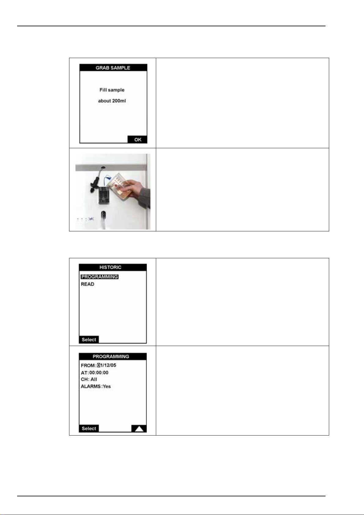
This option allows you to take measurements from an off-line
sample. An initial “Please wait...” screen is displayed while
the measuring cell is rinsed.
Prepare a beaker of 200mL of the sample to analyze.
When rinsing is complete, a screen will be displayed asking
for the sample to analyze (illustrated left).
• First remove the sample level detector from the overflow
vessel and fill the vessel with the sample (illustrated left).
• Replace the sample level detector.
• Press OK to start the measurement.
When the measurement completes, the results are displayed
on screen and a message is displayed to inform you that the
measurement has finished.
7.1.3 Historic
The Esc key can be used to abort the measurement at any
time and return to the previous screen.
This option allows you to view the previously stored
measurements and any alarms that were triggered.
The PROGRAMMING option sets the date (FROM) and the
time (AT) from which the history will be displayed, and the
measurement channels required.
•CH: all channels or a specific channel (1 to 6)
42
• ALARMS (yes or no): if set to yes, displays any system
and warning alarms that were triggered
Page 45
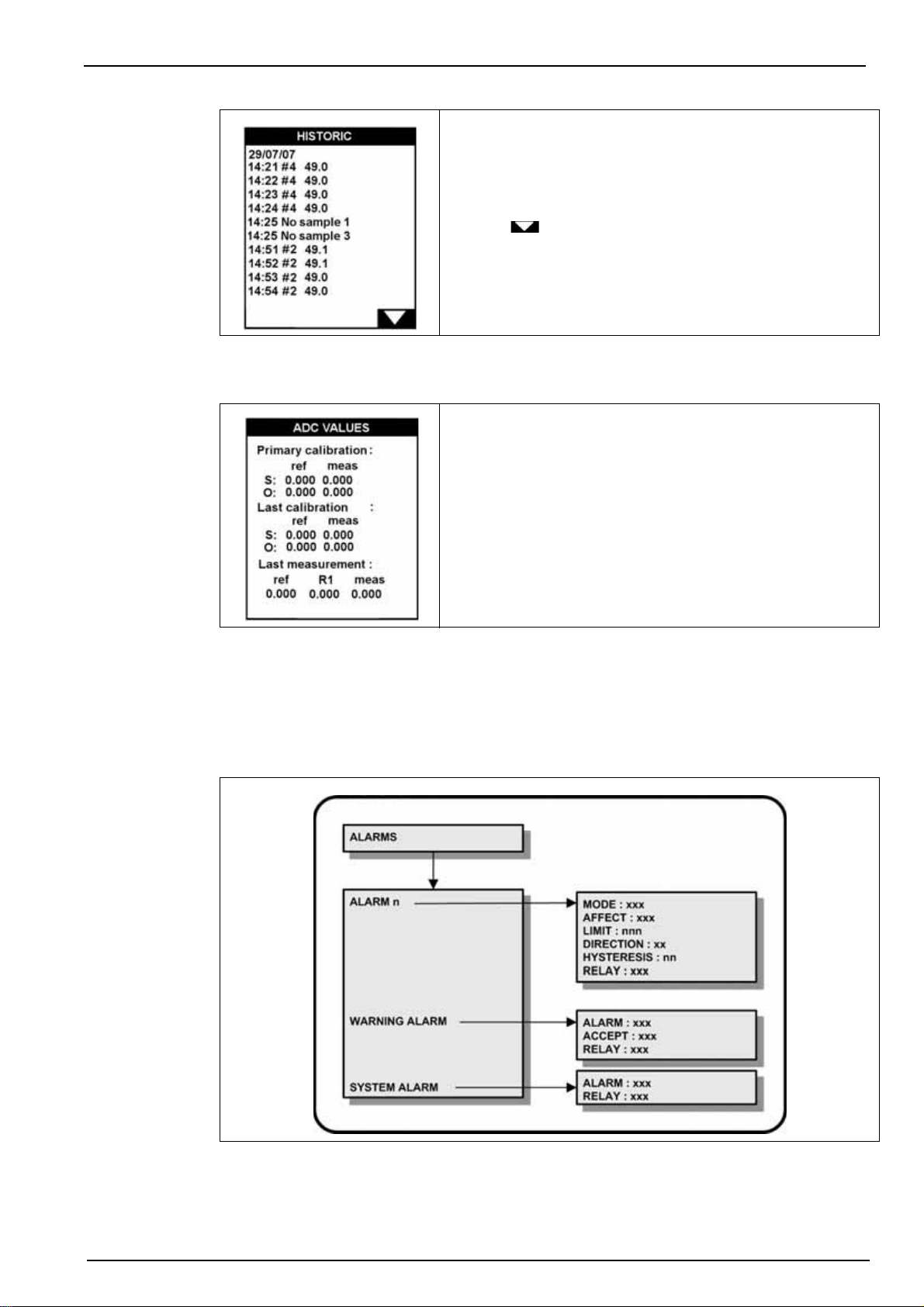
7.1.4 ADC values
User Setup
The READ option lets you view the data as defined by the
parameters set in the programming option.
Use the key to scroll through the list of stored data
which displays the date and time of the measurement, the
channel number, and the measured concentration value.
This option displays the parameters for the primary and last
calibrations, and the last measurement.
7.2 Alarms menu overview
Select the ALARMS option from the main menu to assign alarms and parameters to each relay.
Note: If a PROGRAMMING password has been set (see Code on page 38 for details on how to do this),
you will be required to enter a password to gain access to the main menu.
The information given can be used for diagnostic purposes if
the analyzer appears to be giving incorrect measurements.
43
Page 46
User Setup
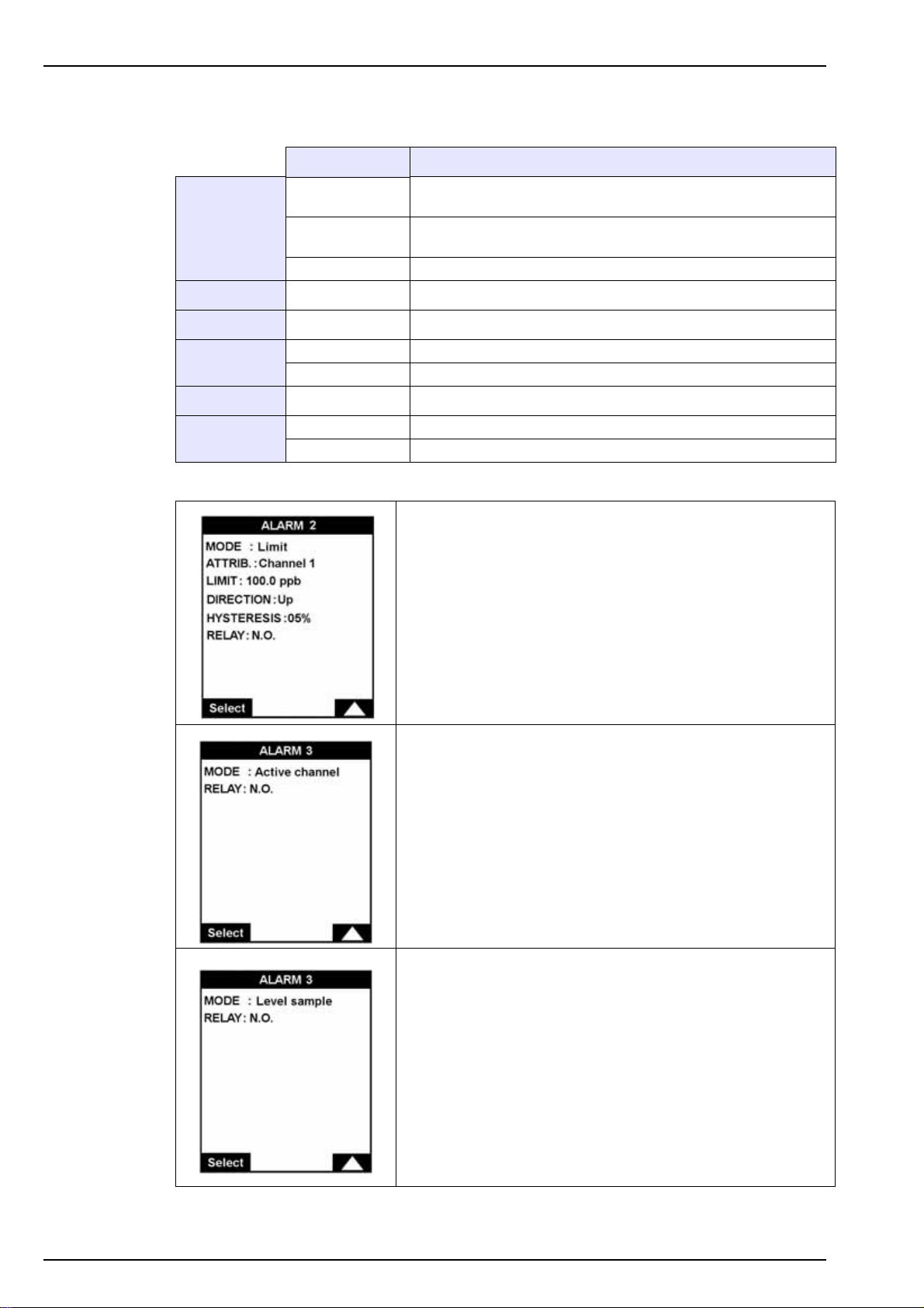
7.2.1 Alarms 1 to 6
MODE
AFFECT Channel 1 to 6 Define the channel on which the alarm is triggered
LIMIT XXXX Define the concentration limit when the alarm is triggered
DIRECTION
HYSTERESIS nn% Hysteresis percentage
Value Description
Limit
Active channel
Level sample Trigger the alarm when there is no sample
Up Trigger the alarm when the measurement is above the limit
Down Trigger the alarm when the measurement is below the limit
Trigger the alarm when the measurement is above or below a
pre-defined limit
Trigger the alarm when the channel is active i.e. during a
measurement cycle
RELAY
N.O. Normally open
N.C. Normally closed
If MODE = Limit
• Define the channel for which alarm 2 will be triggered
• Define the limit value.
• Define if the alarm is triggered when concentration goes
above (Up) or below (Down) the limit.
• Set the hysteresis percentage.
• Define the relay type (normally open or normally closed)
If MODE = Active channel
The alarm is activated when the channel is active (i.e. when
the sample is being measured).
44
If MODE = Level sample
The alarm is activated when the sample is missing.
Page 47
7.2.2 Warning alarm
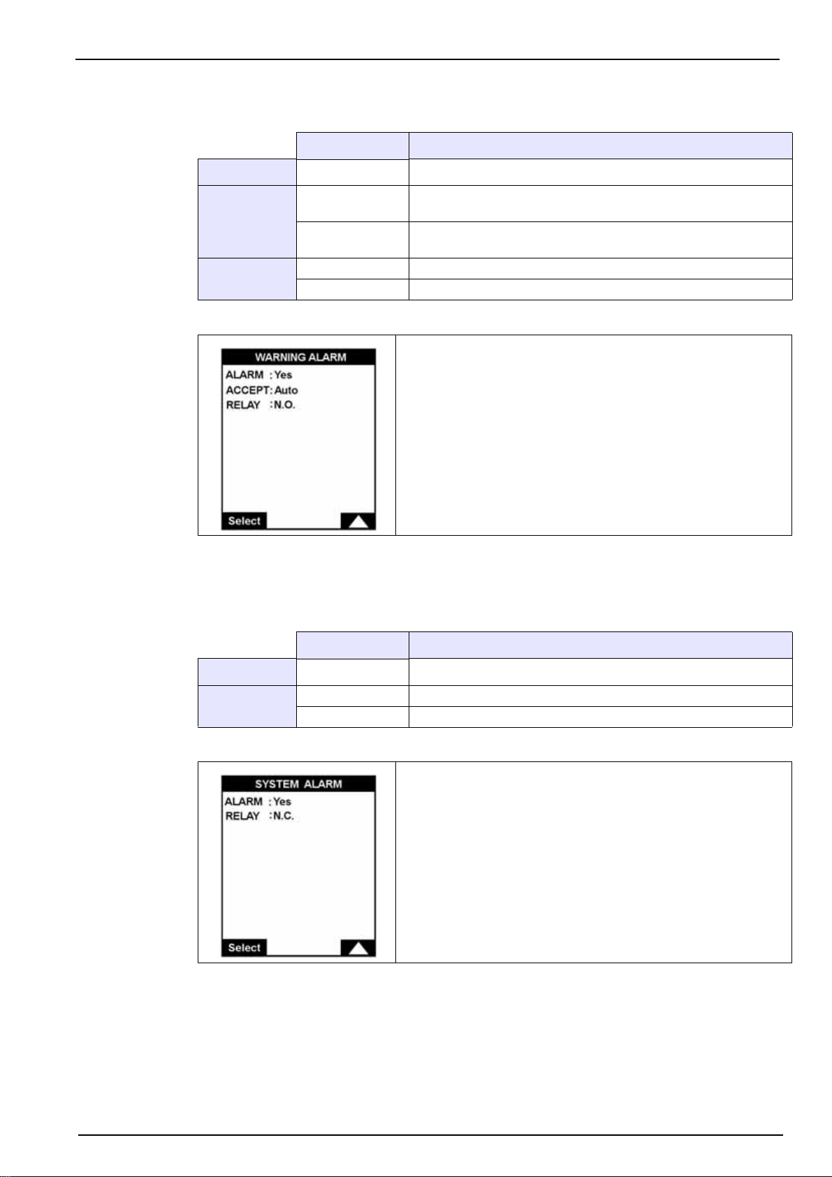
ALARM Yes or No Activate or deactivate the warning alarm
User Setup
Value Description
ACCEPT
RELAY
Manual
Auto
N.O. Normally open
N.C. Normally closed
When the alarm is triggered, it can only be turned off by pressing
the Enter function key
When the alarm is triggered, it will turn itself off when the reason
for the alarm is no longer valid
Define the warning alarm parameters.
Refer to Alarm conditions on page 46 for a list of warning alarm conditions.
7.2.3 System alarm
ALARM Yes or No Activate or deactivate the system alarm
RELAY
Note: The system alarm can only be acknowledged manually, either by holding down the Enter key or,
remotely, by using the digital input, In11 on the I/O card (see Figure 10 on page 27).
Value Description
N.O. Normally open
N.C. Normally closed
Define the system alarm parameters.
Refer to Alarm conditions on page 46 for a list of system alarm conditions.
45
Page 48

User Setup
7.2.4 Alarm conditions
The following table lists all the alarms conditions:
Message Description Type
Reset mod. Measure Reset the measurement module System
Reset module LC Reset the local controller module System
Error lc Local controller module error System
Err. measure mod. Measurement module error System
Comm error Communication error Warning
Table error Error during table transmission System
Task error Task execution error System
Measure error Measurement error Warning
Reference error Problem with current to the LED Warning
Extinction error No current to the LED Warning
Meas.time over Maximum cycle time for measurement has been exceeded Warning
Cal.time over Maximum cycle time for calibration has been exceeded Warning
No sample No sample available System
Sample x missing Sample x missing Warning
Reagent < 250 ml Low level of reagent left (2.5 days before no reagent alarm) Warning
Calib < 300 ml Low level of the calibration solution (max 1 calibration left) Warning
No reagent Empty reagent canisters <150 ml System
Slope drift Slight drift of slope calibration parameter (confirmation zone) Warning
Zero drift Slight drift of zero offset calibration parameter (confirmation zone) Warning
Zero error Zero calibration major error System
Slope error Slope calibration major error System
Sample x < C Sample concentration x is lower than C Warning
Sample x < 0 ppb Sample concentration x is negative Warning
Sample x > 1000 ppb
or > 5000 ppb
Reference error The reference measurement lies outside its max/min values Warning
Sample concentration out of range Warning
Table 2 System and warning error messages
46
• Warning: the analyzer displays a warning on the screen and locks the warning relay.
• System: the analyzer locks the system alarm relay, displays a message and stops.
Page 49
7.3 mA outputs menu overview
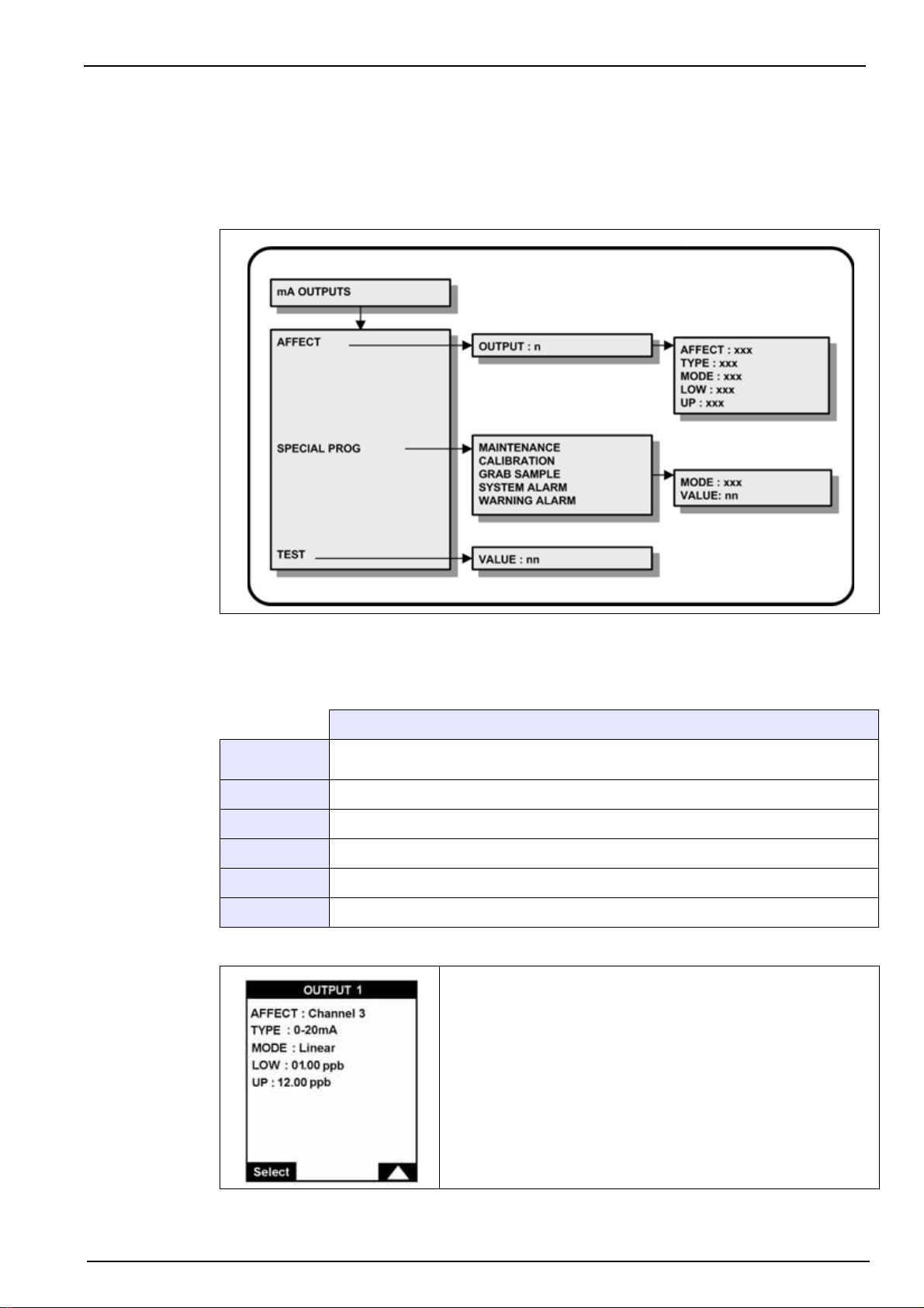
Select the mA OUTPUTS option from the main menu to set the analog output parameters.
Note: If a PROGRAMMING password has been set (see Code on page 38 for details on how to do this),
you will be required to enter a password to gain access to the main menu.
User Setup
7.3.1 Affect
Select the AFFECT option and then each output (1-6) in turn.
Description
AFFECT
TYPE Define the analog output scale (0-20 or 4-20 mA)
MODE Select between linear or dual (see graph in Figure 14)
LOW Value corresponding to the low end of the scale
MIDDLE Value corresponding to the mid-point of the scale (only available in dual mode)
UP Value corresponding to the upper end of the scale
Define the measurement channel (1-6). The measurement on this channel will be
carried over the selected analog output
Define the analog output parameters.
47
Page 50
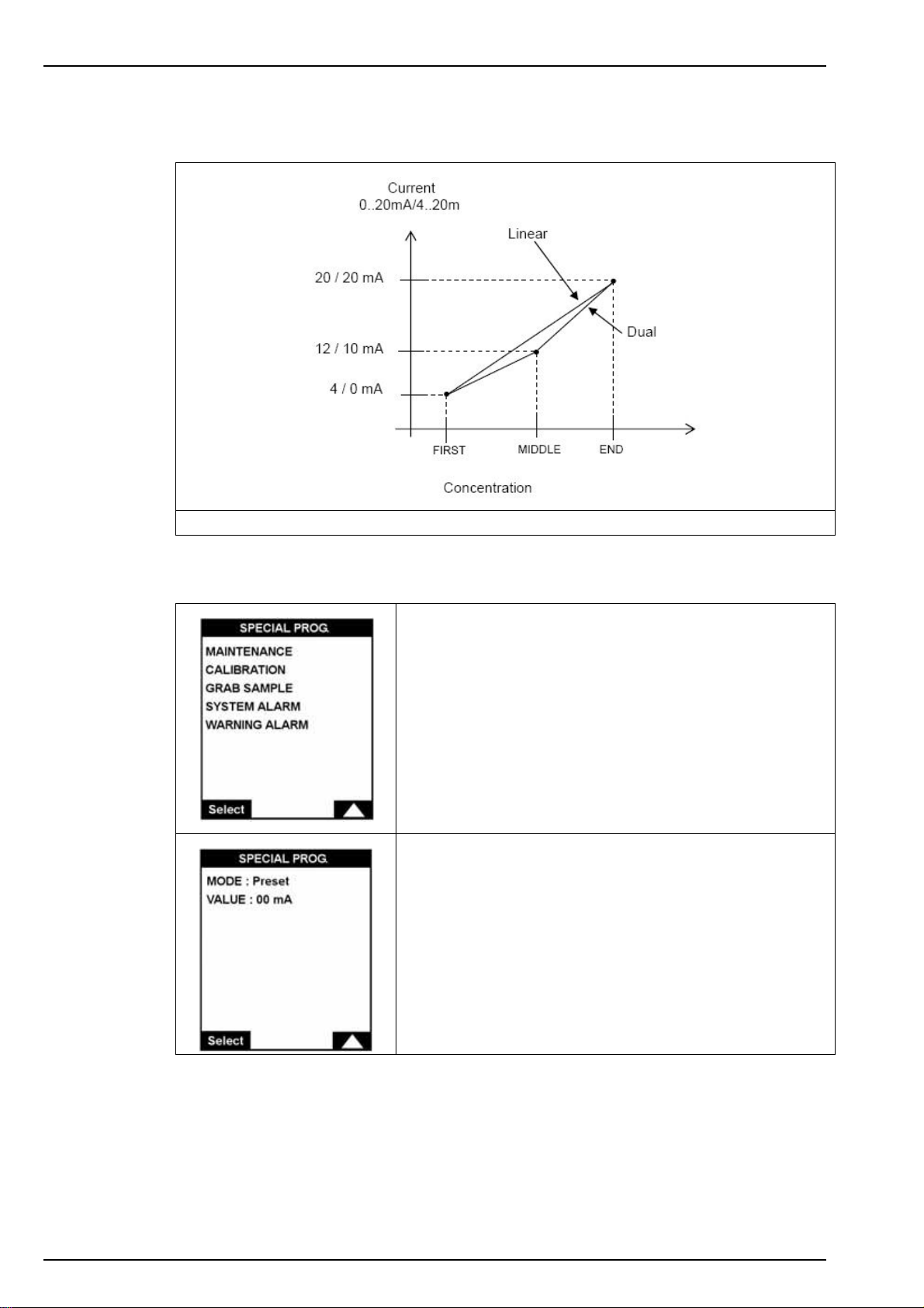
User Setup
The following graph indicates the result of the 4-20 current in relation to the type, and the first,
middle and end value of the scale.
7.3.2 Special programming
Figure 14 Linear and dual slopes
This option lets you program the status of analog output 7 for
the following special events:
• Maintenance
• Calibration
• Grab sample analysis
• System alarm
• Warning alarm
Use the Select function to choose the event for which analog
output 7 is to be assigned.
MODE = Last: Analog output 7 is not changed.
MODE = Preset: Analog output 7 is set to the value defined in
the VALUE parameter.
48
Note: In the case of a system alarm, all the analog outputs (1 to 7) are set to the preset value defined in the
SYSTEM ALARM option.
Page 51
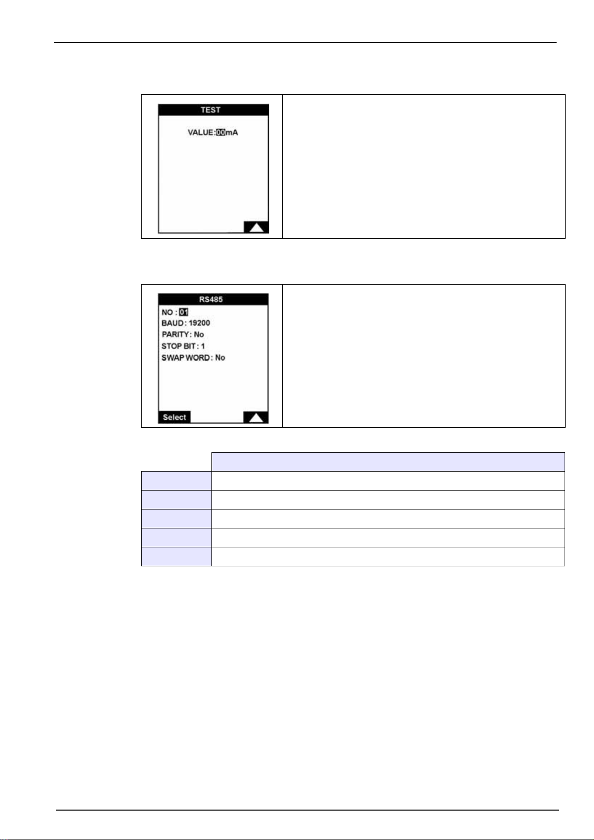
7.3.3 Test
7.4 RS485
User Setup
Test all the analog outputs.
Adjust the current VALUE.
This value is then forced on all analog outputs and can be
verified with the use of a multimeter connected to the
analyzer.
This option allows you to adjust the communication
parameters of the analyzer. The communication protocol is
MODBUS-JBUS.
Description
NO Transmitter number (0 - 33)
BAUD Transmission speed in bauds (300, 600 1200, 2400, 4800, 9600)
PARITY Odd, even, no
STOP BIT 1 or 2
SWAP WORD Lets you reverse the send order of the data
49
Page 52
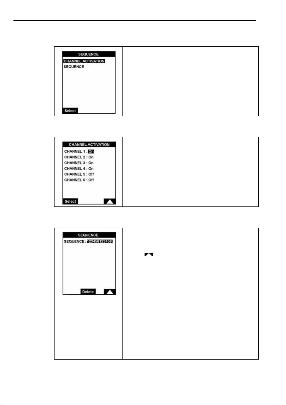
User Setup
7.5 Sequence
7.5.1 Channel activation
The option allows you to activate or deactivate the
measurement channels, and to define the order in which the
samples are measured.
7.5.2 Sequence
The CHANNEL ACTIVATION option defines which channels
are active and which are not.
The SEQUENCE option displays the configured sequence
and lets you change it.
The sequence is set up in 12 steps.
Use the key to change the number of the channel.
The Delete key replaces the number by the asterisk symbol.
This symbol indicates no measurement for that step in the
sequence.
Sequences examples:
1. 1 2 3 4 5 6 * * * * * *
4 5 6 3 2 1 * * * * * *
50
These two sequences analyze samples (1 to 6) in a different
order.
2. 12 12 12 12 12 12
or 12 ** ** ** ** **
or 1* 2* ** ** ** **
These three sequences have the same effect and set the
analyzer to measure channels 1 and 2 alternately.
Page 53
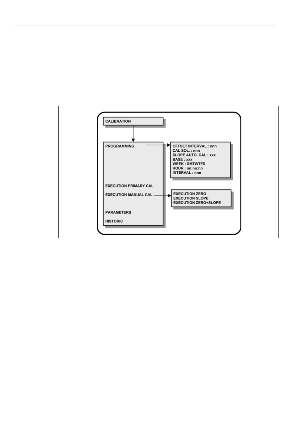
Section 8 Calibration
Before attempting to setup the analyzer, ensure you have read and understood how to enter
and change data fields as described in the section entitled Data Entry on page 33.
8.1 Menu overview
Select the CALIBRATION option from the main menu.
Note: If a PROGRAMMING password has been set (see Code on page 38 for details on how to do this),
you will be required to enter a password to gain access to the main menu. In addition, if a CALIBRATION
password has been set, you will also be required to enter this password to get access to the calibration
menu.
For continued accurate measurements, the analyzer should be calibrated on a regular basis.
Calibrations allow the adjustment of:
• ZERO of the system
• SLOPE of the system
• Both ZERO and SLOPE of the system
The ZERO calibration is performed chemically by the analyzer. In order to avoid the use of
water free of SiO
slope of the system is then calibrated with a standard solution of known concentration of SiO
Three types of calibration are available:
• Primary
• Manual
• Automatic
In addition, the CALIBRATION menu also gives access to the current calibration parameters
and a history of previous calibration results.
, the analyzer carries out a measurement without a colorimetric reaction. The
2
.
2
51
Page 54
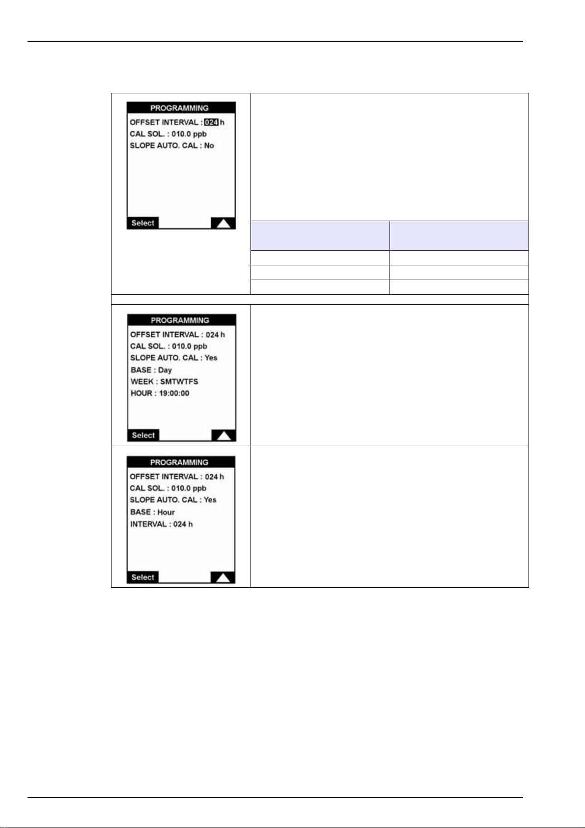
Calibration
8.1.1 Programming (automatic calibration)
This option is used to define the parameters for an automatic
calibration.
The programming screen lets you define the frequency of the
zero calibration, the concentration of the calibration solution
and to choose between an automatic or manual calibration.
The following table indicates the recommended frequency of
the zero calibration in terms of the minimum concentration of
the samples.
Sample minimum
concentration
< 5 ppb 24 hours
5 < x < 50 ppb 48 hours
> 50 ppb > 72 hours
Recommended frequency
For an automatic slope calibration, this screen lets you define
the frequency.
• When the BASE option is set to Day, the WEEK option
sets the calibration day(s).
Ex 1: SMTWTFS, for a daily calibration.
Ex 2: SM*W*FS, for a calibration every day except
Tuesday and Thursday.
• The HOUR option is used to set the time to start the
calibration.
• When the BASE option is set to Hour, the INTERVAL
option sets the frequency of the slope calibration. The
recommended slope calibration frequency is 1 week (168
hours).
52
Page 55
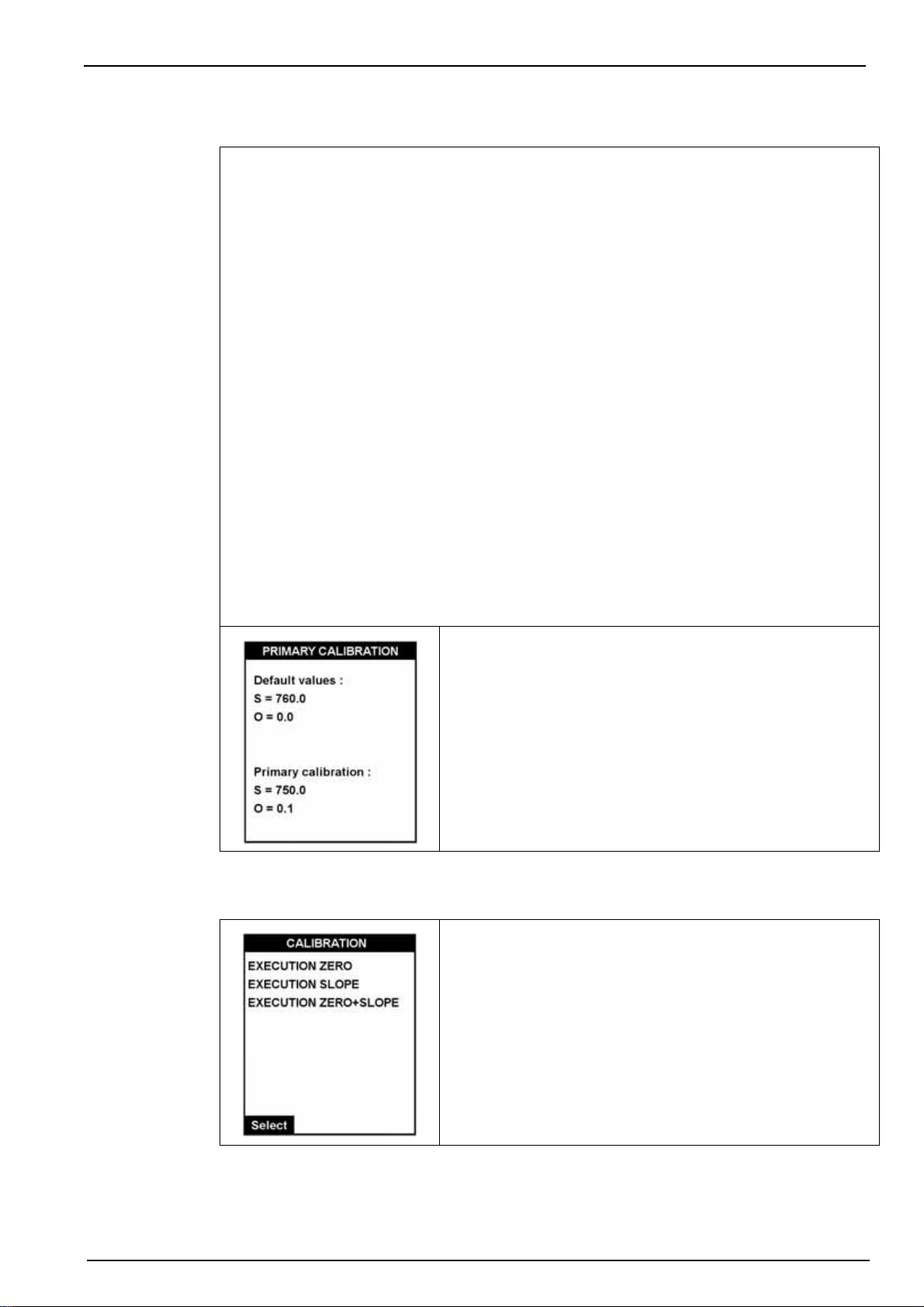
8.1.2 Execution primary calibration
A primary calibration is carried out at the factory and is used as a reference for all following
calibrations.
In general, this type of calibration does not need to be repeated unless important changes
have been made to the analyzer.
Important Note: If you feel that a primary calibration is required, please discuss this with your
Hach Lange representative for advice and assistance before performing this type of calibration
on your analyzer.
The primary calibration sets the slope and zero references. All results of further manual or
automatic calibrations will be compared to the zero and slope references set by this
calibration. Large differences will signify an error in the calibration and will be highlighted with
an error message.
The calibration of the slope is defined first, followed by the zero.
Press Esc to abort the calibration and return to the CALIBRATION menu.
The calibration is made in the following stages:
• Sample preparation
Calibration
• Conditioning
• Measurement
• Rinse
A bar graph indicates the calibration progress.
8.1.3 Execution manual calibration
At the end of the calibration, the results are displayed on
screen.
Primary calibration results:
S = value of the slope (ppb / Abs)
O = value of the zero shift in milli-Abs
The default values show a general idea of the standard values
according to the analyzer range (0-1000 or 0-5000 ppb).
Choose the type of calibration required:
•ZERO
•SLOPE
• ZERO + SLOPE
At the end of the calibration, the results will be displayed (see
example in Historic on page 54).
53
Page 56
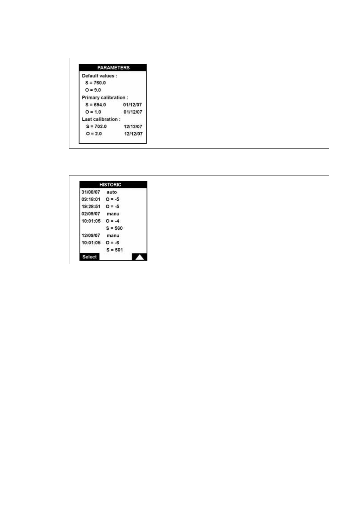
Calibration
8.1.4 Parameters
8.1.5 Historic
This screen displays the primary calibration parameters and
the last calibration parameters.
The default values show a general idea of the standard values
according to the analyzer range (0-1000 or 0-5000 ppb).
This screen displays the calibration history with the following
information:
• Date and time.
• Type: manual or automatic.
• Slope (S) and offset (O) values.
54
Page 57
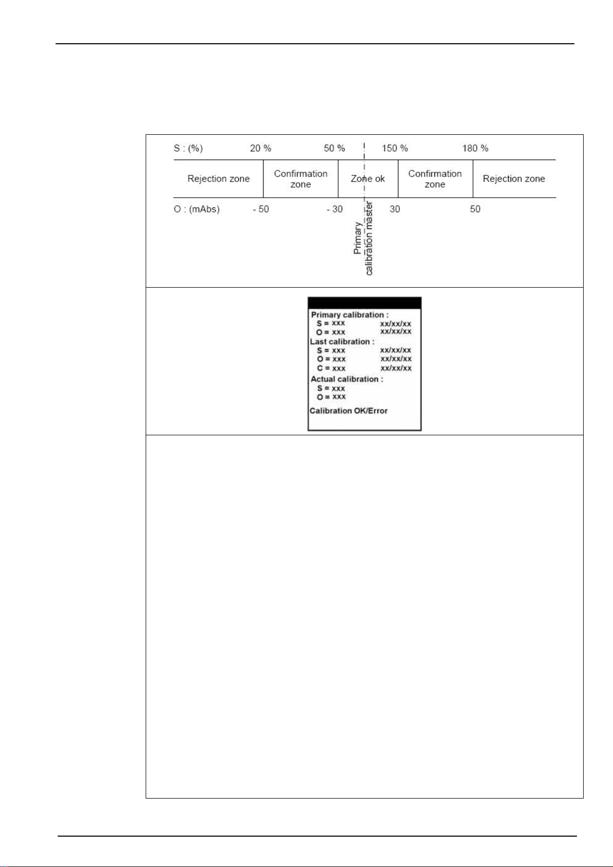
8.1.6 Calibration results
At the end of a manual or automatic calibration, the analyzer compares the results with the
primary reference calibration parameters. Depending on the results, you can accept, restart or
cancel the calibration. There are 3 zones:
Calibration
Zone ok
Normal variations compared to the reference values. The new parameters are acceptable.
In automatic mode, the analyzer returns to its measurement cycle. In manual mode, validate
with OK and restart the analyzer (Start function key).
S: XXXXX DD:MM:YY - Slope
O: XXXXX DD:MM:YY - Offset
C: XXXXX DD:MM:YY - Concentration of the sample solution just measured, calculated using
the calibration values from the Last calibration.
Confirmation zone
Abnormal variations compared to the reference values. The new parameters can be accepted
but a warning is displayed and confirmation is required.
In automatic mode, the analyzer does not take the new parameters, but returns to
measurement mode with the previous parameters. In manual mode, you must confirm (Conf)
or cancel (Cancel) to accept or reject the new parameters.
Note: In automatic mode, where the calibration lies within the confirmation zone, the analyzer takes one
measurement and then recalibrates. After 3 successive invalid calibrations, the analyzer waits for the next
programmed date before attempting another calibration.
Rejection zone
Parameters are abnormal. There is a basic problem such as an invalid calibration solution
preparation being used.
In automatic mode, the analyzer stops and triggers a system alarm. In manual mode, you can
Cancel (return to measurement mode with the previous parameters) or Restart the
calibration.
55
Page 58

Calibration
56
Page 59
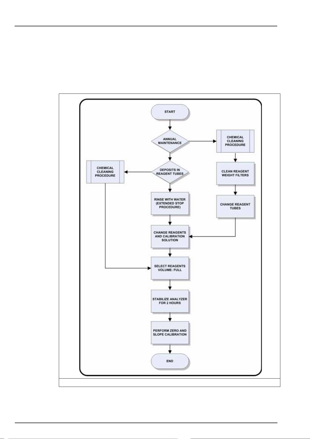
Section 9 Maintenance
9.1 General
Periodic maintenance will ensure accurate and consistent analysis results. Verify the level of the
calibration and reagent solutions on a regular basis and refill if necessary.
9.2 Cleaning overview
9.2.1 General cleaning process
Figure 15 Cleaning overview
57
Page 60
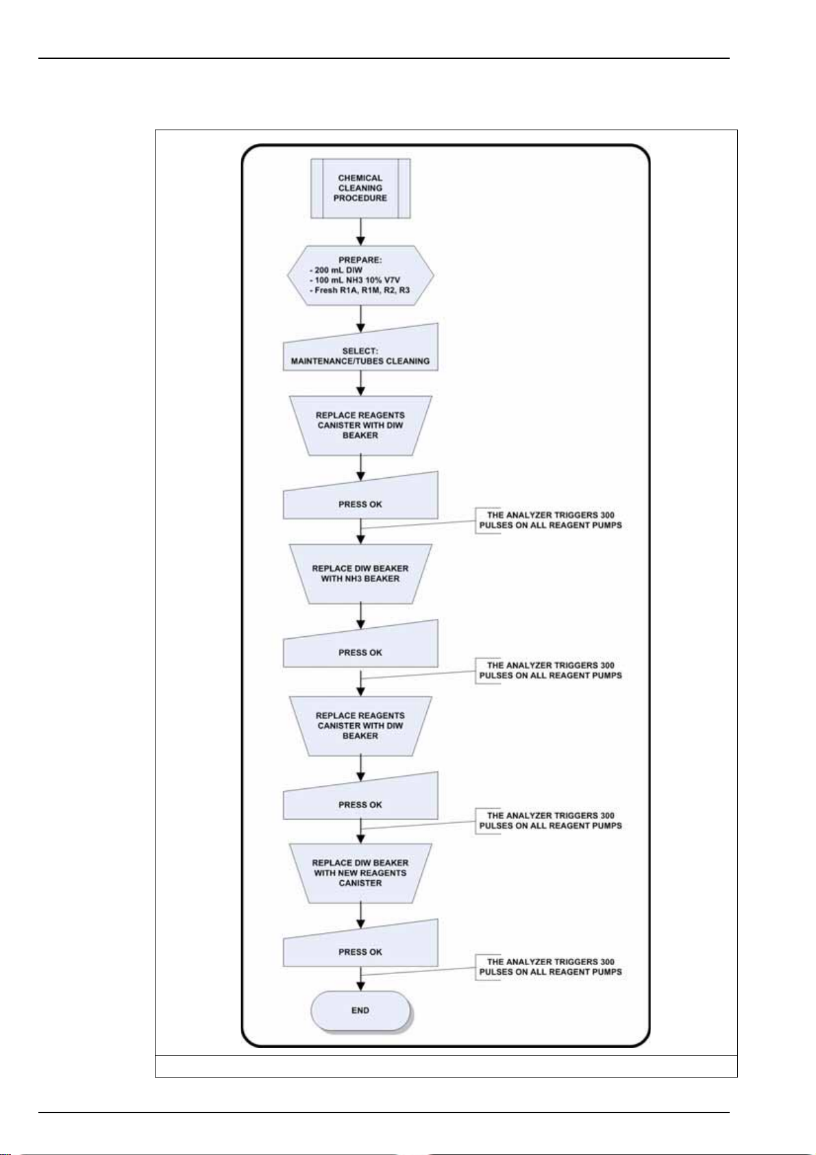
Maintenance
9.2.2 Chemical cleaning procedure
58
Figure 16 Chemical cleaning procedure
Page 61
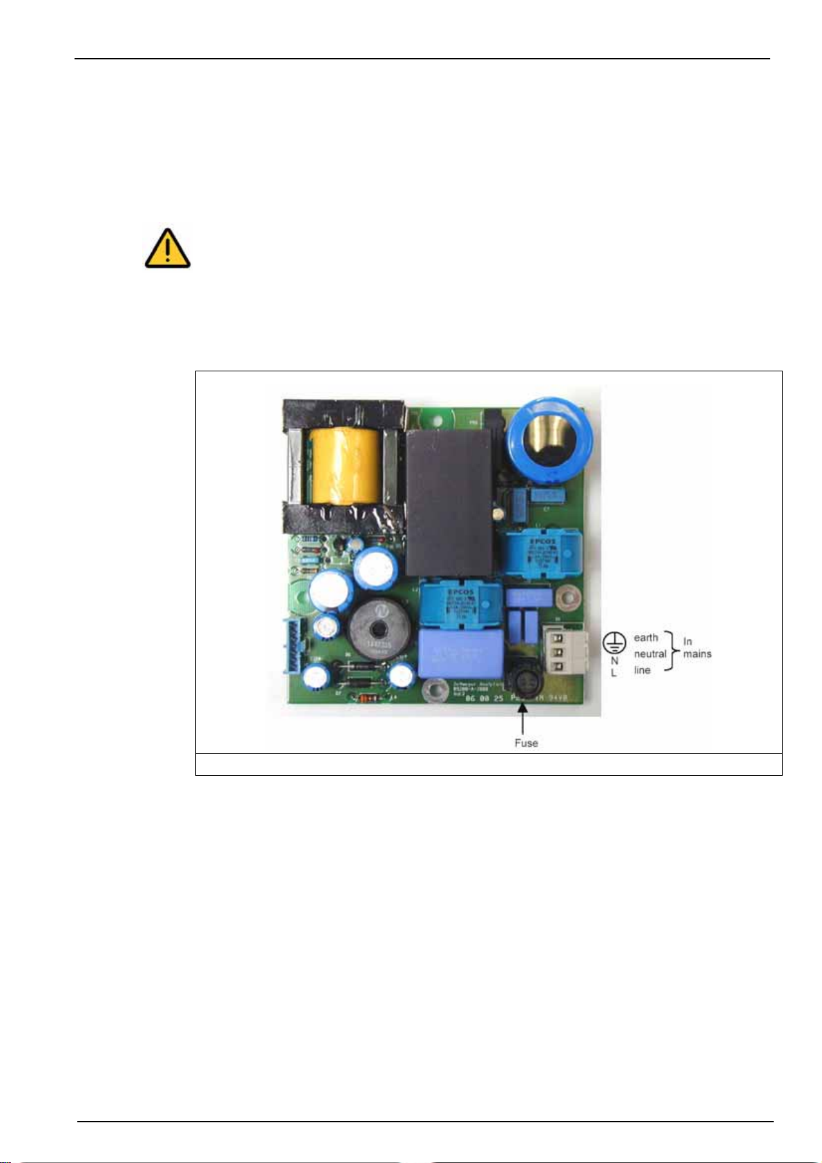
9.3 Battery replacement
The transmitter is delivered with a CR1220 (3V) lithium battery included to safeguard the time
function in the analyzer when not powered up. Should this internal battery malfunction or require
replacement it must be replaced with exactly the same battery type CR1220 (3V) UL Certified
(compulsory VARTA, RENATA or MATSUSHITA).
WARNING
There is a risk of explosion if the replacement battery does not correspond to the correct
model as indicated above. Do not throw away used batteries, but send them to a local
recycling center.
9.4 Fuse replacement
The following illustration shows the position of the fuse, which is located next to the mains
connectors on the power supply board under the shielding plate.
Maintenance
Figure 17 Fuse location
Replacement fuses are supplied with the analyzer and these must be used to replace faulty or
blown fuses. If for any reason these replacements are not available, only the following
alternatives should be used:
• JDYX2, LITEFUSE, type 213, rated 2 AT, 250 VAC
• JDYX2, SIBA, Type 179120, rated 2 AT, 250 VAC
• JDYX2, SCHURTER, Type FST, rated 2 AT, 250 VAC
If there is any difficulty in obtaining these replacement fuses, please contact your local Hach
Lange representative for advice and assistance.
59
Page 62
Maintenance
9.5 Yearly maintenance
Once a year, maintenance should be carried out on the analyzer to ensure the high degree of
accuracy of the analyzer is maintained. This maintenance requires the following maintenance kit
which is available from your local Hach Lange representative:
Part No. Description
09210=A=8000 2 years spare part kit 921X (all ranges). Includes items and quantities below
The following step-by-step process should be followed:
1. Ensure that adequate warning has been given to all personnel that are involved in any
way with the analyzer, that maintenance will be carried out on a pre-defined date/time.
2. Shut down the analyzer as follows:
8 x 589=010=015 Fitting for 1.5mm I.D tubing - 10/32 UNF thread
8 x 590=050=060 Polyethylene tubing 1.6 x 3.2mm (per meter)
8 x 625=065=025 Printed stickers for tubing identification
1 x 09210=A=8050 Kit of (8) ferrules, (8) nuts
8 x 09210=A=4362 Injectors
2 x 226=003=013 Teflon coated magnetic stirrer (for 921X analyzers)
0.5 x 151400,22387 PE tubing 6 x 8mm (per meter)
1.0 x 151575,00006 PE tubing 4 x 6mm (per meter)
a. Stop the analyzer measuring process by pressing the Stop function key
b. Press the Menu function key and select the MAINTENANCE option
c. Select the EXTENDED STOP option
d. Fill a beaker with 250 mL of demineralized water
e. Open the analyzer to gain access to the reagent and calibration solution canisters
f. Unscrew the caps on the 4 reagent canisters, remove the tube guides from the
canisters and place them in the beaker of demineralized water
g. Unscrew the cap on the calibration solution canister, remove the tube guide from
the canister and place it in a second (empty) beaker. Do not put it in the beaker of
demineralized water containing the reagent tube guides
h. Press OK to start the rinsing process
i. On completion press Esc to exit the process. The measuring cell and reagent
tubes will now be rinsed and empty
j. Disconnect the analyzer from the power source
3. With the analyzer still open, remove the 4 screws holding the pump box cover in place
(item no. 8 in Figure 3 on page 16) and set to one side.
Note: The pump connections are described on the pump box cover. Each pump has an inlet tubing
(from the canister to the pump) and an outlet tubing (from the pump to the measuring cell). The
outlet tubing is also referred to as the injector.
4. Prepare 4 of the injectors (part no. 09210=A=4362 from the maintenance kit). The
process is slightly different depending on the analyzer model in use (sulfuric acid or nitric
acid chemistry).
60
9120 analyzer with sulfuric acid chemistry:
a. The injector is supplied with the ferrule and fitting nut attached. These are not
required, so cut the tubing immediately after the ferule (90° angle) and discard the
ferrule and nut. Do this on all 4 injectors
9120 analyzer with nitric acid chemistry:
a. No action is required and the tubing injectors should be used as supplied in the
maintenance kit
Page 63
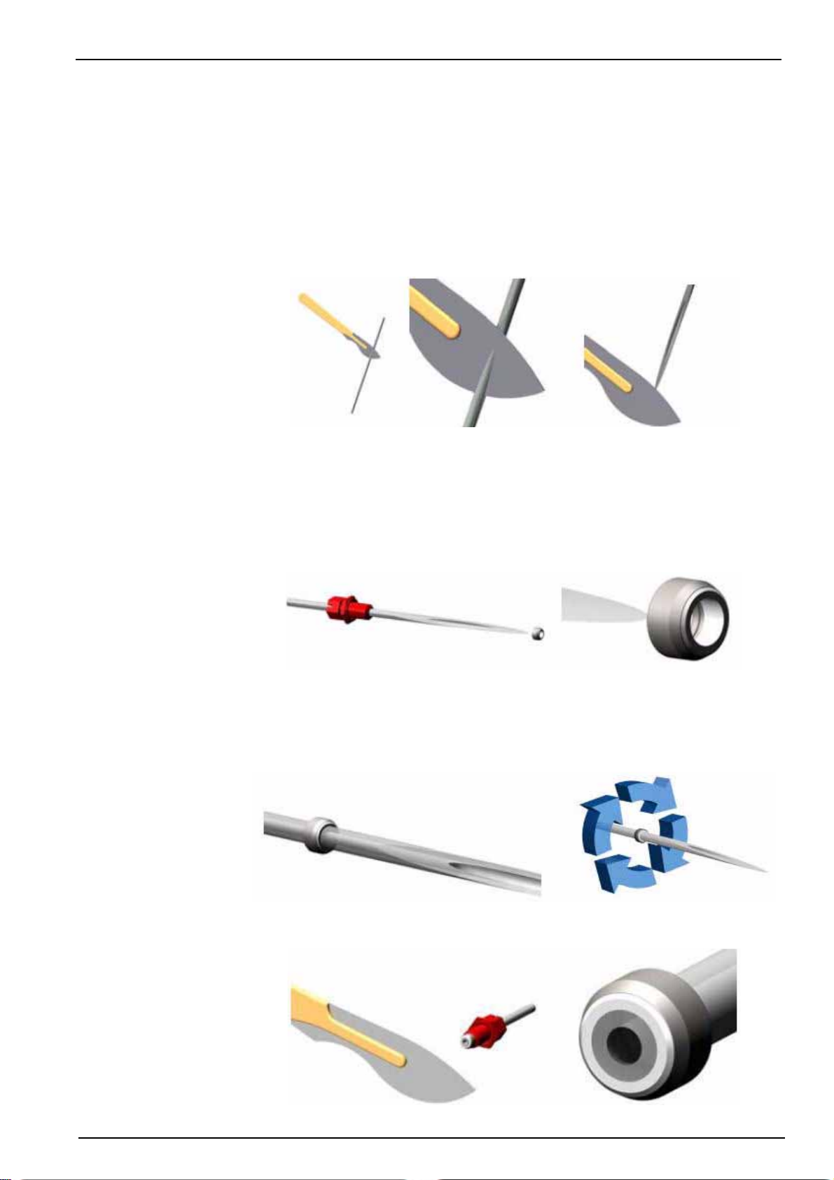
Maintenance
5. Prepare the inlet tubing (part no. 590=050=060 from the maintenance kit). Again, the
process is slightly different depending on the analyzer model in use (sulfuric acid or nitric
acid chemistry).
9120 analyzer with sulfuric acid chemistry:
a. Cut 4 lengths of tubing of 90 cm each and proceed to the step 6
9120 analyzer with nitric acid chemistry:
a. Using a scalpel, cut one end of the tubing to form a point approximately 30mm
long, to enable the tube to be passed through the ferrule:
WARNING
Always take care when using scalpels. Always make tube cuts away from the body
and keep fingers away from the blade.
b. Slide the fitting nut onto the tube. Slide the ferrule over the pointed end and onto
the tube as far as possible without forcing it, and ensuring the PTFE seal is facing
towards the pointed end of the tube:
c. With the aid of long-nosed pliers or similar, pull the pointed tube end through the
ferrule until the PTFE sealing surface has reached the uncut section of the tube.
Keeping the ferrule as perpendicular as possible to the tube will ensure the best
results. Rotate the ferrule around the tube 3 or 4 times to seat the ferrule on the
tube correctly:
d. Using a scalpel, cut the pointed tube end as close to the ferrule as possible,
ensuring the end of the ferrule is not cut:
61
Page 64
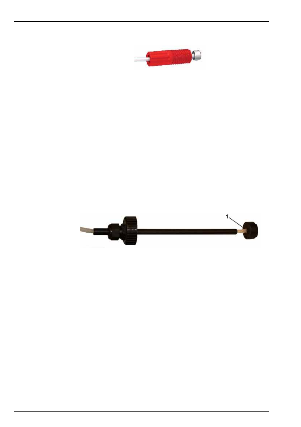
Maintenance
e. The tube assembly is now ready for use:
6. Renew all the reagent tubing.
Important Note: To avoid any contamination, ensure that each tube guide is always
used for the same reagent as it was previously used for. Under no circumstances should
they be interchanged.
Apply the following procedure for one reagent, then repeat for each reagent in turn. For
easier access, start with the reagent pump on the far left (closest to the calibration
pump).
a. Locate the inlet port (nearest to you) and outlet port (farthest from you) of the
pump. Be aware that there is an additional port on each pump between the inlet
and outlet ports but which is not to be used. Disconnect the inlet tubing and the
injector tubing from the pump. Pull the injector tubing out of its position in the
photometric cell (item no. 5 in Figure 2 on page 15) and discard it
b. Mount the newly prepared injector on the outlet port of the pump and screw in
place. Slide the other end of the tubing through the panel cut-out at the front but
do not yet connect to the photometric cell
c. Mount the newly prepared inlet tubing on the inlet port of the pump and screw in
place
d. Retrieve the old inlet tubing and the tube guide from the beaker of water
e. Unscrew the plastic fitting from the weight (position 1 in the illustration below) and
put the weight to one side on a clean tissue
f. Once the weight is removed, pull all the old reagent tubing out of the tube guide
and discard
g. Slide the newly prepared reagent tubing through tube guide
h. Place a new fitting (part no. 589=010=015 from the maintenance kit) on the end of
the tubing and screw into the weight
i. Take the same sticker as the original one (part no. 625=065=025 from the
maintenance kit) and place it around the reagent tube approximately 10cm from
the tube guide
j. Place the tube guide assembly back in its canister and screw down securely
k. Repeat these steps for the next reagent pump until all four have been completed
7. Change the magnetic stirrer in the photometer cell by first removing the 4 screws from
the photometric cell cover. Put the screws to one side. Lift off the cap and then remove
the old magnetic stirrer in the bottom of the cell.
Take a new stirrer (226=003=013 from the maintenance kit) and place in position at the
bottom of the cell.
Replace the photometric cell cover and secure with the 4 screws.
8. Place the ends of the injectors into the top of the photometric cell as far as they will go
without forcing them.
62
Page 65
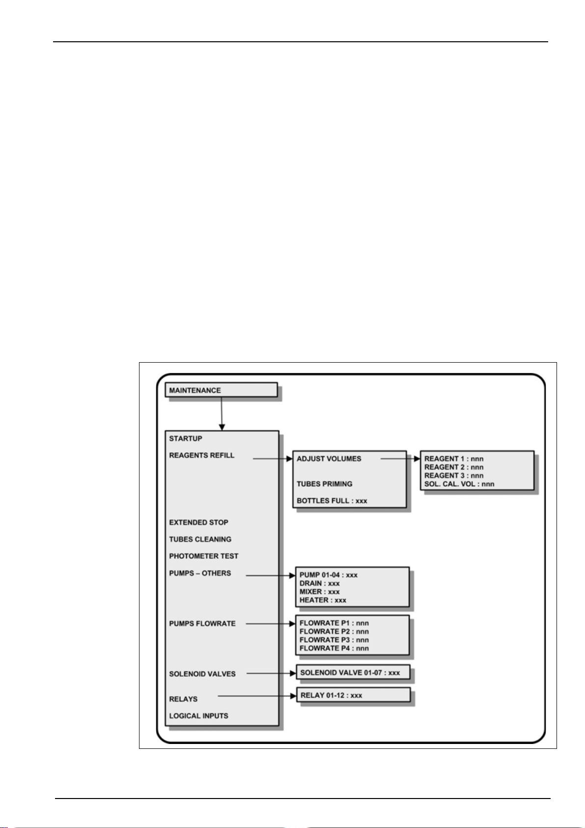
9. Re-connect power to the analyzer. Once the measurement screen is displayed, select
the Menu option and then MAINTENANCE. Then select the REAGENTS REFILL option
and then the TUBES PRIMING option. This will purge and refill the new calibration and
reagent tubing, and will take about 20 minutes to complete.
At the end of the process press Esc to return to the menu at which stage the new
reagent tubes should be full of reagent.
10. Return to the measurement screen and press the Start function key to begin
measurements. Leave the analyzer to run for a period of two hours after which the
measurements will have stabilized.
11. Once stable, press the Stop function key to stop measurements. Then select the Menu
option and then CALIBRATION. Perform a manual ZERO+SLOPE calibration.
After a successful calibration the analyzer is ready to resume measurements. Return to
the measurement screen and press the Start function key.
9.6 Maintenance menu overview
There are a number of maintenance and diagnostic procedures that can be performed using the
analyzer software.
Select the MAINTENANCE option from the main menu.
Maintenance
Note: If a PROGRAMMING password has been set (see Code on page 38 for details on how to do this),
you will be required to enter a password to gain access to the main menu.
63
Page 66
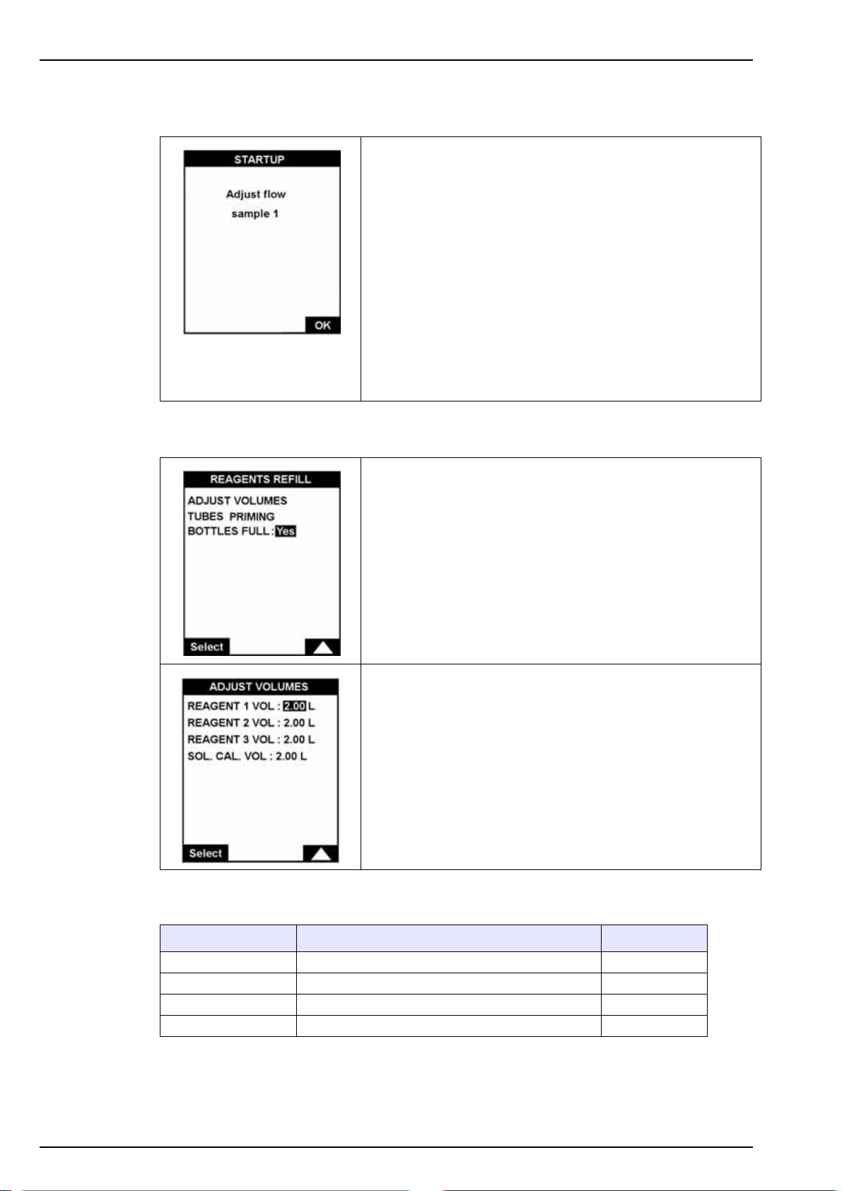
Maintenance
9.7 Startup
9.8 Reagents refill
This option is used after the analyzer has not been used for
an extended period of time, or when starting the analyzer for
the very first time.
Using a screwdriver, set the flow rate for the first sample using
the adjustment screws on the front panel (item 4 in Figure 2
on page 15). Regulate the flow (between 5 and 30 L/hour) to
ensure a slight overflow into the overflow vessel.
Note: Do not completely unscrew the adjustment screw as it has no
stop and may provoke a sample leak.
Select OK to continue to the next sample channel.
When all channels have been set, the pumps are primed.
Check visually that the tubes are full and then press Enter to
return to the menu.
Each time the reagent and calibration solutions are
replenished, access this menu for:
ADJUST VOLUMES: the canister volumes are displayed and
can be modified.
TUBES PRIMING: start the priming / renewal procedure of the
reagents in the tubes.
BOTTLES FULL: choose this option each time the canisters
have been refilled. The volumes are automatically reset to 2
liters.
If ADJUST VOLUMES has been selected in the menu above,
the current volumes of the reagent canisters and the
calibration solution are displayed.
These can be individually modified.
The analyzer monitors the reagent and calibration solution consumption. Messages are
displayed when the solution levels are low.
64
Message Reason Relays set
Reagent < 250ml Low reagent level (range < 10 days) Warning (Re 11)
Cal. Sol < 300ml Calibration low level (range < 2 calibration) Warning (Re 11)
Short reagent Reagent canister volume < 150ml System (Re 12)
Short cal. Calibration solution canister volume < 150ml
Page 67
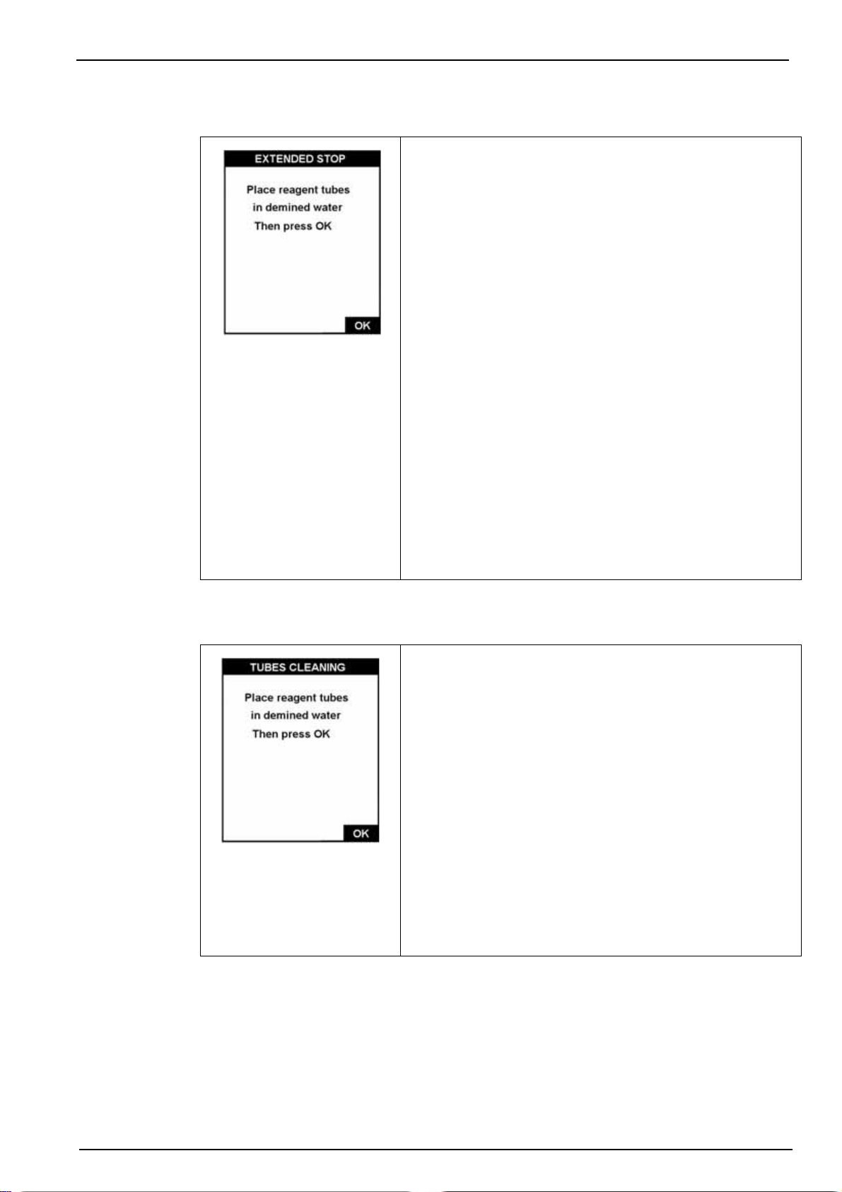
9.9 Extended stop
Maintenance
In case of an extended stop (longer than 1 week) it is
recommended to clean the tubes and the measuring cell.
Have a beaker of 250 ml of demineralized water available and
then do the following:
• Stop the analyzer by pressing Stop
• Press the Menu key
• Select the MAINTENANCE menu
• Select the EXTENDED STOP option
• Submerge all the reagent tubes in the beaker of
demineralized water
• Press OK to start each stage of the procedure
• Follow the instructions on screen and validate each stage
with OK.
At the end of the process, the measuring cell is empty.
Disconnect the power from the analyzer and replace the
reagent tubes in their canisters.
9.10 Tube cleaning
Note: Do not interchange the tubes. They must be returned to the
exact same canister they were taken from.
In case of an extended stop of over 6 weeks, you must
discard the reagents and prepare another set for the restart.
If the tubes become clogged, use this procedure to clean
them.
Have a beaker available containing 250ml of demineralized
water and a second beaker containing 100ml of ammonia at
10% of normal commercial concentrations by volume i.e.
approximately 3% V/V.
Immerse tubing R1A in the ammonia solution. Press OK to
start the cleaning process.
Follow the instructions and press OK at each step.
The procedure is the following:
• Rinse the tube with demineralized water
• Clean with a 10% ammonia solution
• Rinse the tube again with demineralized water
On completion, press Esc to return to the previous screen.
65
Page 68
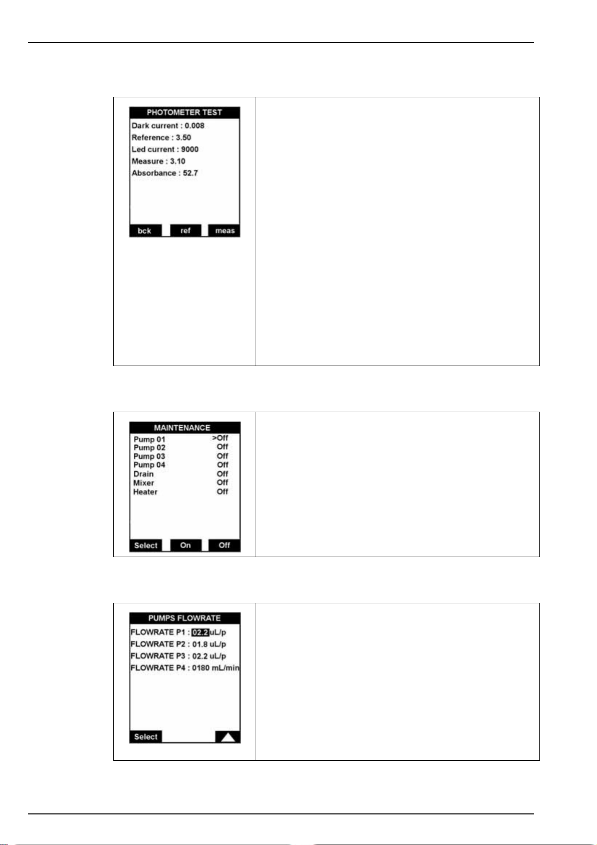
Maintenance
9.11 Photometer test
With this option, technicians can verify the correct functioning
of the photometer. During the process, the mixer is operating
and the transfer valve is open.
Displayed parameters:
• Dark current: Measurement value which corresponds to
the LED emission.
• Reference: Reference signal after LED current
adjustment.
• Led current: Current of the LED.
• Measure: Continuous photometric measurement signal.
• Absorbance: Absorbance in milli-Abs.
Function keys:
•bck: Begins the measurement which corresponds to
switching off the LED.
9.12 Pumps - others
9.13 Pumps flowrate
•ref: Allows adjusting the LED current and to measure the
reference voltage.
•meas: Starts the continuous photometric measurement.
This option verifies the correct functioning of the pumps, the
mixer, the drain and the heater.
Use the Select key to verify an element and press the On key
to operate it or Off key to stop it.
A label is affixed to each pump indicating the flow rate which
has been factory defined.
66
Enter this value into the respective field:
• P1 - Reagents R1A and R1M
• P2 - Oxalic acid
• P3 - Reducer
• P4 - Calibration pump
Note: The information for the calibration pump is used to determine
the consumption of calibration solution, so that an alarm can be
triggered when the solution gets low.
Page 69
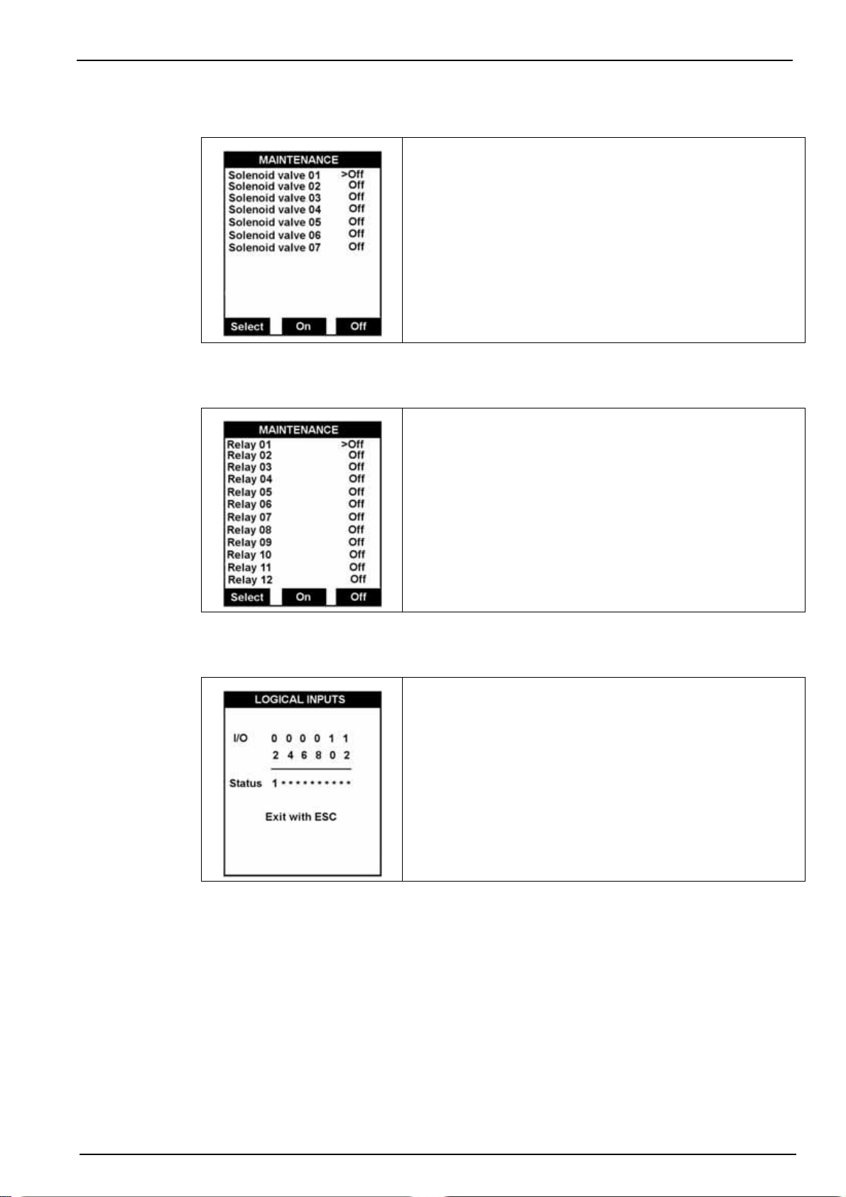
9.14 Solenoid valves
9.15 Relays
Maintenance
This option verifies the correct functioning of the solenoid
valves.
Use the Select key to verify a valve and press the On key to
operate it or Off key to stop it.
Press Esc to return to the previous screen.
• Solenoid valves 01 to 06: Measuring channels 1 to 6.
• Solenoid valve 07: Sample transfer from overflow vessel
to the measuring cell.
9.16 Logical inputs
This option operates or stops the relays.
Use the Select key to select a relay and press the On key to
operate it or Off key to stop it.
Note: For each relay function, refer to Table 1 on page 28.
This option displays the status of the logical inputs and
verifies the functionality of the inputs In1 to In12.
Status: 1 = short circuit input
* = open input
67
Page 70
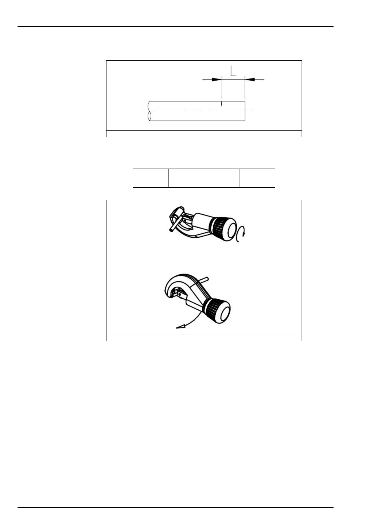
Maintenance
9.17 Preparation of the tubes for insertion in the fast connectors
Figure 18 Groove location
Mark where the groove is to be located, using the following table:
Tube length 6 mm 1/4'' 5/16''
L7.3 ± 0.5 0.33 ± 0.02 0.36 ± 0.02
68
Figure 19 Make a groove in the tube
1. Place the tube in the cutter with the cutting wheel on the mark.
2. Tighten the tool a quarter of a turn.
3. Rotate the tool around the tube and check a small groove has been cut all round the tube.
4. Remove the tube from the cutter.
Page 71
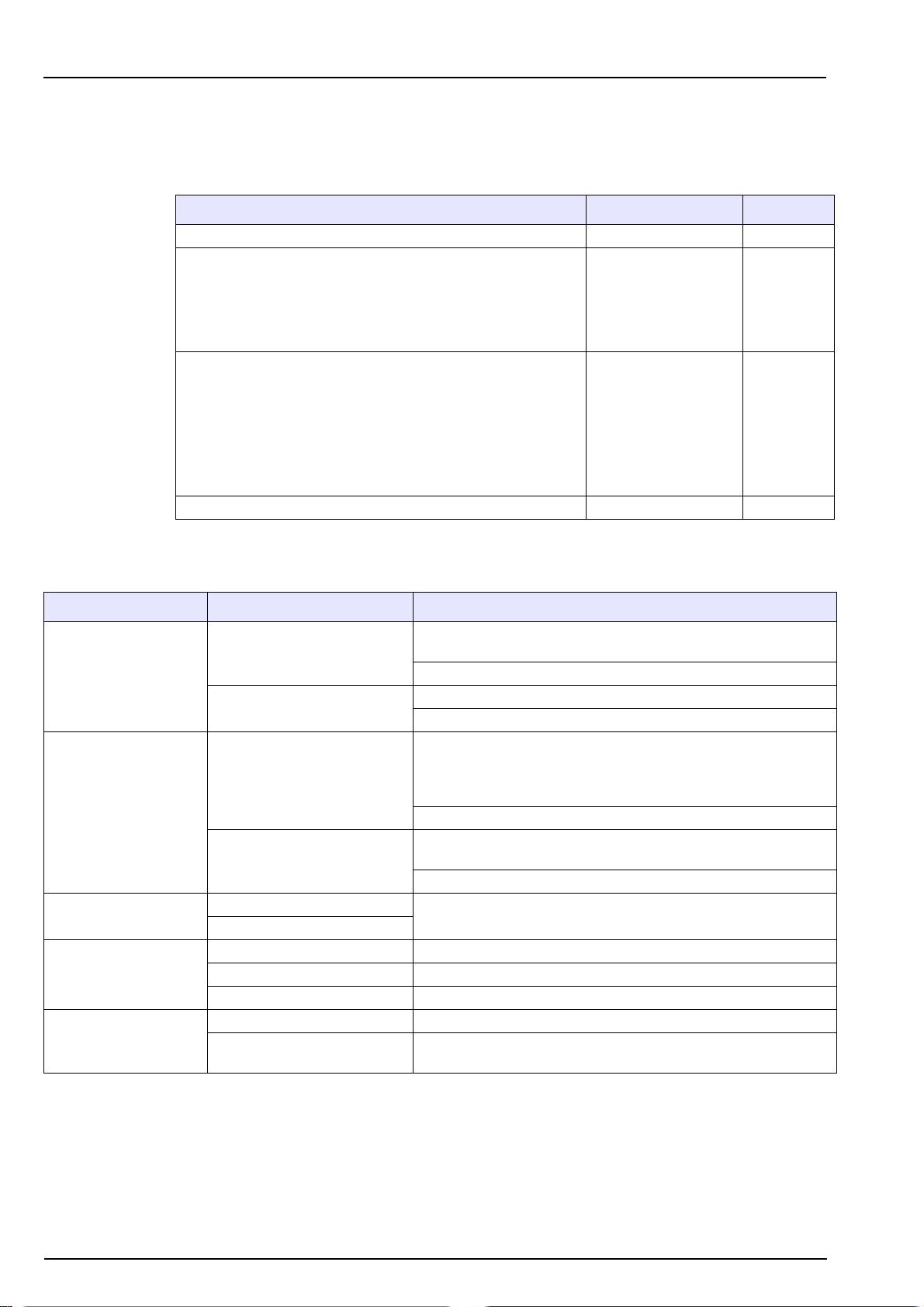
Section 10 Troubleshooting
10.1 Possible sources of the problem
This list gives you an idea of where to look for problem solving if you are having problems with
your analyzer.
Problem Possible cause Problem N°
The system does not run Start / Stop 1
The measurement is not stable, too high or too low
Incorrect calibration
The photometer does not run or measure correctly Photometer 8
Sample
Tubes
Photometer
Valves
Pump
Pump
Tubes
Valves
Calibration solution
Calibration program
Reagents
Photometer
5
3
8
4
2
2
3
4
6
7
7
8
10.2 Possible solutions
Problem Symptom Solution
System alarm: Rectify the problem according to the message
displayed (see Table 2 on page 46).
Start up the analyzer by pressing the Start key.
Connect the analyzer to the mains power.
Check the fuse.
Test the pump. In the MAINTENANCE / PUMP - OTHERS menu
the number of pulses is automatically set to 1,000. Start each
pump one after the other and verify that the volume obtained per
pump is between 2.5-3 mL (corresponding to 2.5-3 μL/pulse).
Change the pump.
The analyzer may have been stopped without cleaning the tubes.
Using a syringe, flush the pump with clean water.
Change the pump.
Change the tube.
Verify and adjust the flow (10 L/h), change the sample tube if it is
clogged.
1. START / STOP
2. PUMP
3. TUBES
4. SOLENOID VALVES
5. SAMPLE
Analyzer stopped
Mains power cut off
Does not run
Irregular
Defective tube
Clogged tube
Solenoid valves leak Remove, test and clean.
The solenoid valves can't open Stuck membrane; cleaning required.
The solenoid valves can't close Blocked outlet; cleaning required.
Dirty Disconnect the sample lines from the sample block.
Diminution of the flow
69
Page 72
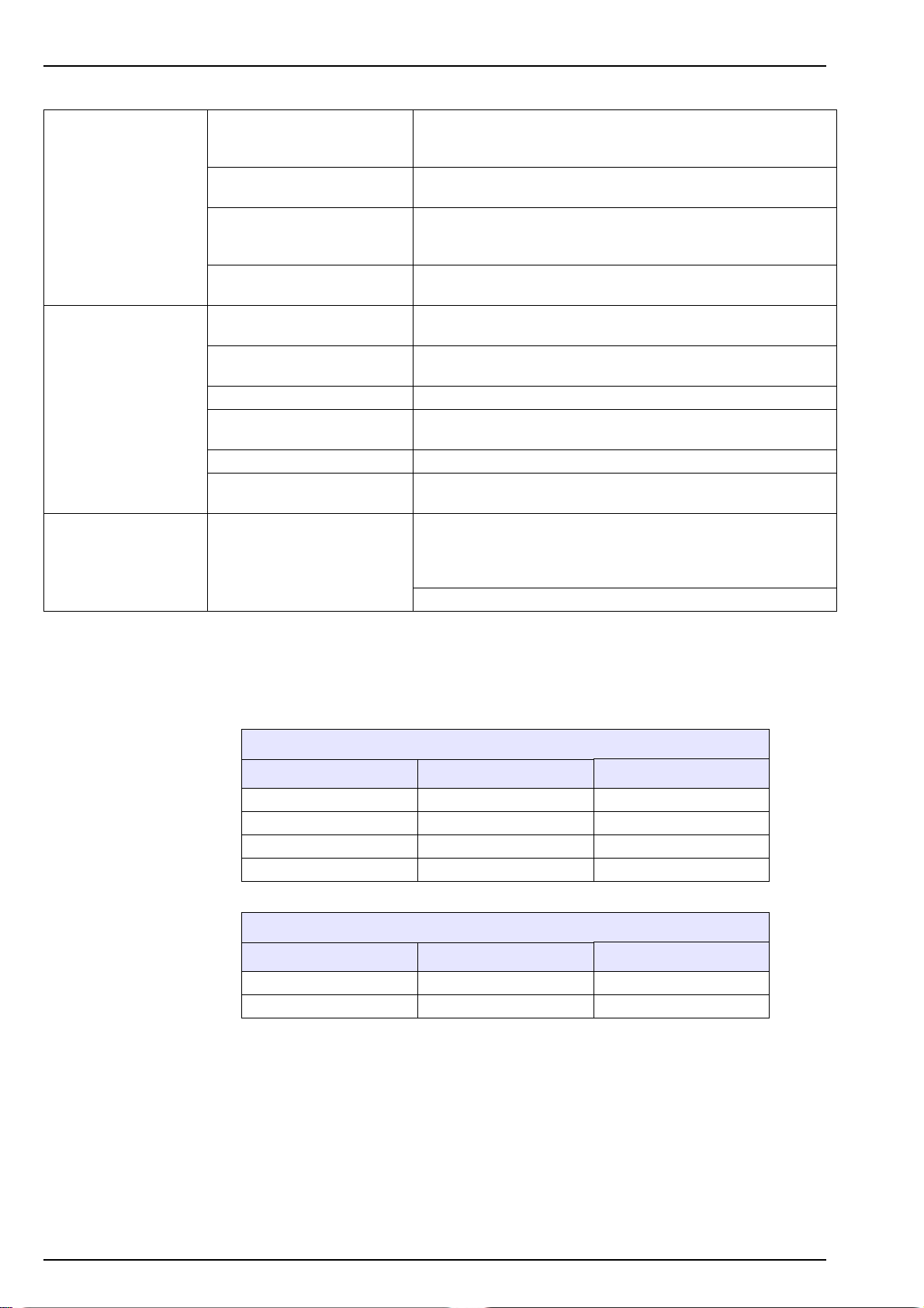
Troubleshooting
6. CALIBRATION
7. REAGENTS
8. PHOTOMETER
Wrong configuration of the
calibration solution
concentration
Wrong concentration of the
standard solution
Wrong laboratory analysis of
the calibration solution
concentration
Wrong chemical products or
old or contaminated
Reagent canisters connected
in the wrong order.
Reagent tubes connected in a
wrong order.
Wrong concentration Prepare a new batch of reagents.
Wrong chemical products or
old or contaminated
Wrong proportion of reagent Check the pumps.
Bacterial development in
reagent R3 (greenish deposit)
Wrong or irregular
measurement
Reprogram the calibration solution concentration (SiO2).
Prepare a new standard solution.
Verify the SiO2 concentration of the laboratory calibration solution.
Wrong purity? New supplier? Clean the reagent bottles.
Verify the flow of the circuit from the MAINTENANCE /
PUMPS-OTHERS menu.
Verify the flow diagram.
Wrong purity? New supplier?
Add 40 ml of sodium benzoate at 1 g/L.
Verify the photometer in MAINTENANCE / PHOTOMETER TEST.
In this menu measurement values of reference and measurement
during the last calibration of the measurement cycle appear. The
typical values of these are in the tables on page 70.
Is there an error message?
10.3 Typical measurement values during calibration
These values are indicative and depend on the ambient temperature. The real values may
deviate by more than one volt without having any effect on the measurements.
Version 0 - 1000 ppb
Sample concentration Reference (mV) Measure (mV)
107 ppb 3500 2515
214.9 ppb 3500 1754
267.4 ppb 3500 1472
534.8 ppb 3500 603
Version 0 - 5000 ppb
Sample concentration Reference (mV) Measure (mV)
1000 ppb 3500 1400
3000 ppb 3500 300
70
Page 73

Section 11 Spare Parts
Accessories
09125=A=1485 Kit for Profibus DP with board for 91xx / 92xx and Operator Manual
09125=A=2485 Optional RS485 JBUS/MODBUS for transmitters model 91XX after February 2004 (CPU-ph2) or 92XX
after June 2006 (CPU-ph2): board + instruction manual (5 languages)
09210=A=8000 2 years spare part kit 921X (all ranges). Includes items and quantities below
8 x 589=010=015 Fitting for 1.5mm I.D tubing - 10/32 UNF thread
8 x 590=050=060 Polyethylene tubing 1.6 x 3.2mm (per meter)
8 x 625=065=025 Printed stickers for tubing identification
1 x 09210=A=8050 Kit of (8) ferrules, (8) nuts
8 x 09210=A=4362 Injectors
2 x 226=003=013 Teflon coated magnetic stirrer (for 921X analyzers)
0.5 x 151400,22387 PE tubing 6 x 8mm (per meter)
1.0 x 151575,00006 PE tubing 4 x 6mm (per meter)
09210=A=8012 9210-ph2 Analyzer tech spare part kit. Includes items and quantities below:
1 x 09210=A=0250 Sample level sensor for 921X
1 x 09210=C=7010 9210 set of dry chemicals for 50 days operation
1 x 09210=A=8072 Kit of 5 empty canisters w/caps & stickers for 9210-ph2 silica
1 x 689=118=008 Sampling solenoid valve, NPS 0.8 (0.2 - 6 bars)
1 x 689=118=024 Sampling electrovalve (overflow vessel)
1 x 695=004=004 Calibration / flush pump
1 x 09210=A=8040 micro-dosing diaphragm self-priming pump
09210=A=8072 Kit of 5 canisters w/caps & stickers for 9210-ph2 silica (for dry chemicals see 09210=C=7010)
09210=C=7010 9210 set of dry chemicals for 50 days operation (applicable for all 9210 generation)
G-MC-9210 GOLD-Contract, Maintenance & Calibration, Analyzer Silica (SiO
P-MC-9210 PLATINUM-Contract, Maintenance & Calibration, Analyzer Silica (SiO2), 9210
S-MC-9210 SILVER-Contract, Maintenance & Calibration, Analyzer Silica (SiO
MC-9210 Maintenance & Calibration, Silica (SiO
Spare parts in contact with sample
09210=A=0100 0.5 - 6 bars adaptation kit for 6 solenoid sample valves
09210=A=0105 Sampling flow-rate adjustment screw (w/ its O-ring)
09210=A=0110 Metric to imperial conversion assembly (for one channel) from connector 6 mm O.D. to 1/4'' O.D. acetal
09210=A=0111 921X sample valve kit (uneven to even number)
09210=A=0121 Complete 1 channel block for 921X
09210=A=0122 Complete 2 channels block for 921X
09210=A=0143 Complete 3 channels block for 921X
09210=A=0144 Complete 4 channels block for 921X
09210=A=0165 Complete 5 channels block for 921X
09210=A=0166 Complete 6 channels block for 921X
09210=A=0250 Sample level sensor for 921X
356099,05040 Viton O-ring 4 x 1 mm of the sampling flow-rate adjustment screw.
356099,35380 Viton O-ring 38 x 2 mm (around level detector)
359110,52012 Tubing silicone 12 x 17 mm (per meter) - from 8810 vessel or 921x, 924x column to drain 689=118=008 Solenoid valve (24CC, 2/2way) as per 9210&9211 sample blocks [NPS 0.8 (0.2 - 6 bars)]. Delivered with
one connector P/N 350=005=377. For mounting, see special torx screw driver at P/N 820=000=006
689=118=016 Solenoid valve (24CC, 2/2way, NPS 1.6 (0.2 - 2 bars)). Delivered with one connector P/N 350=005=377.
For mounting, see special torx screw driver at P/N 820=000=006
689=118=024 Solenoid valve (24CC, 2/2way) as per 9210&9211 overflow vessel (AKA transfer valve). For connector,
see P/N 350=005=377. For mounting, see special torx screw driver at P/N 820=000=006
Spare parts in contact with cell or electrodes
09097=C=0560 Heating element
09210=A=0300 Complete photometer cell for 921X
09210=A=0400 Complete mixer for 921X analyzers
09210=A=0500 Hollow fiber for 921X
) analyzer, 9095/9097/9210
2
), 9210
2
), 9210
2
71
Page 74

Spare Parts
09210=C=0310 PVC square cover for 921X photometric cell
09210=C=0330 Spacer ring for 921X mirror
09210=C=0340 Mirror for 921X analyzers
226=003=013 Teflon coated magnetic stirrer (for 921X analyzers)
356099,05220 O-ring Viton 22 x 1 mm (around mirror)
356099,15040 Viton O-ring for use on 8873 temperature sensor, 8362 pH-probe and 921X hollow fiber
359000,40780 Pt100 temperature sensor
431=100=210 Colorimetric cell nut PG21 - Brass coated nickel
Spare parts in contact with reagents or standard solution
08891=A=0040 Cap for 9210 5L canister with hole for reagent tubing
09210=A=0600 Weight with filtration-grid for 921X reagent canisters
09210=A=7100 Set of 4 stickers 4 for 9210 canisters "Declaration of content". Stickers only.
09210=A=8040 Kit micro-dosing diaphragm pump, self priming, with tubing-connectors-screws ready for mounting on
9210-ph2
09210=A=8080 Tube guide including weight and filtration grid, for 2 liter canister of 9210, 9211, (for chemicals see
09210=C=7000, for canister-kit see 09210=A=8070, for reagent-tubing see 590=050=060)
09210=C=0005 Canister holder for 921x (for canister and stickers, see 0921x=A=8070)
09210=C=0630 Filtration-grid for weight of 8810 or 921X reagent canisters
09210=C=7000 9210 set of dry chemicals for 45 days operation
09210=C=7010 9210 set of dry chemicals for 50 days operation (applicable for all 9210 generation)
148644,05125 Fitting - nipple type - 10/32 UNF for 1/8" or 4 mm tubing
151065,08699 PTFE tubing Ø 0.8 x 1.6 mm (per meter)
151575,00006 Tubing in PE (low density), Ø 4 x 6 mm (per meter)
495=020=001 2 liter PE canister with plain cap
584=024=024 Union fitting PP for 4 mm tubing
589=010=015 Fitting for 1.7 mm I.D. tubing – 10/32’’ thread
589=011=040 Fitting for 4 mm I.D. tubing – 10/32’’ UNF thread in PP
590=050=060 Tubing in PE (low density), Ø 1.6 x 3.2 mm (per meter)
695=004=004 Pump 24 VDC, membrane, 0.1 L/mn, for 921x calibration/flush pump
Electronics spare parts
09200=A=1001 CPU board with display for Monec E9200
09200=A=1010 CPU board with display for Monec E9200, loaded with 9210 latest software
09200=A=2000 Power supply board for Monec E9200
09200=A=5000 User connections / Interface board for 9210 & 9211
09200=A=5500 921X Internal bus communication module
09210=A=1234 Connection board for 921X mixer/heater
09210=A=1500 Colorimetric measurement module for (0-1K_SiO
09210=A=1510 Colorimetric measurement module for (0-5K_SiO2) applications.
09210=A=1520 Colorimetric measurement module for (0-50_PO
425=210=022 Cable gland PG21 PP grey equipped with anti-bend protection for diameter sizes 13 to 18 mm
Additional hardware
820=000=006 Elbow torx screw driver T6
Documentation
221=092=010 Operator manual in French for POLYMETRON 9210 Silica, A4 format
221=192=010 Operator manual in English for POLYMETRON 9210 Silica, A4 format
221=292=010 Operator manual in German for POLYMETRON 9210 Silica, A4 format
221=492=010 Operator manual in Italian for POLYMETRON 9210 Silica, A4 format
221=592=010 Operator manual in Spanish for POLYMETRON 9210 Silica, A4 format
/ 0-5_PO4) applications.
2
) application.
4
72
Page 75
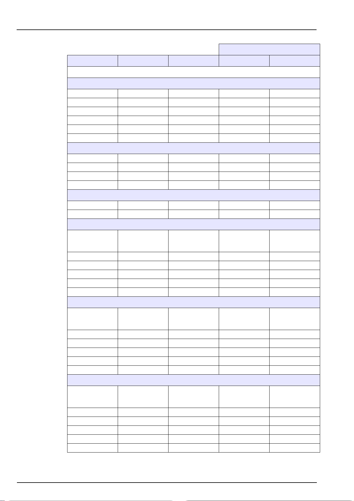
Section 12 Default Configuration
Parameter Default value Possible values Selected values Date
CALIBRATION / PROGRAMMING
Offset interval 24 hours 1 - 999 hours
Cal. sol 214 ppb ppb / ppm
Auto. cal No Yes / No
Base Day Day / Hour
Week SMTWTFS SMTWTFS
Hour 15:00:00 24 Hour clock
MAINTENANCE / REAGENTS REFILL / ADJUST VOLUMES
Reagent 1 2.00 L 0 - 5 L
Reagent 2 2.00 L 0 - 5 L
Reagent 3 2.00 L 0 - 5 L
Calibration solution 2.00 L 0 - 5 L
User configuration
MEASURE / MEASURING MODE
Cycle In loop Interval / In loop
Interval 15 mins 1 - 999 mins
ALARMS / ALARM 1
Limit
Mode Limit
Affect Channel 1 Channel 1-6
Limit 1000 ppb
Direction Up Up / Down
Hysteresis 0% 0 - 10%
Relay N.O. N.O. / N.C.
Mode Limit
Affect Channel 2 Channel 1-6
Limit 1000 ppb
Direction Up Up / Down
Hysteresis 0% 0 - 10%
Relay N.O. N.O. / N.C.
Mode Limit
Affect Channel 3 Channel 1-6
Limit 1000 ppb
Direction Up Up / Down
Hysteresis 0% 0 - 10%
Relay N.O. N.O. / N.C.
Active channel
Level sample
ALARMS / ALARM 2
Limit
Active channel
Level sample
ALARMS / ALARM 3
Limit
Active channel
Level sample
73
Page 76
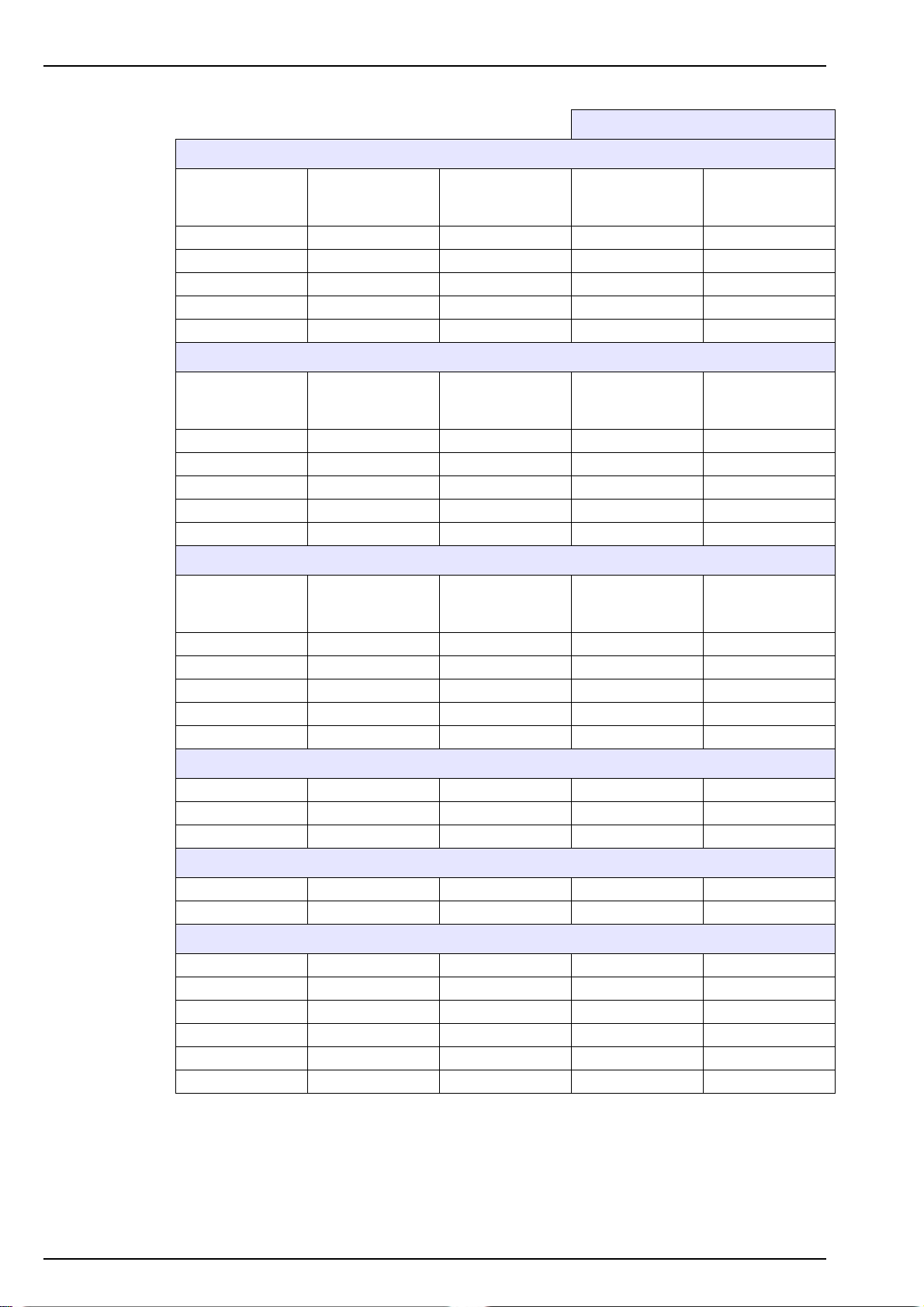
Default Configuration
Mode Limit
Affect Channel 4 Channel 1-6
Limit 1000 ppb
Direction Up Up / Down
Hysteresis 0% 0 - 10%
Relay N.O. N.O. / N.C.
Mode Limit
Affect Channel 5 Channel 1-6
Limit 1000 ppb
Direction Up Up / Down
Hysteresis 0% 0 - 10%
Relay N.O. N.O. / N.C.
Mode Limit
Affect Channel 6 Channel 1-6
Limit 1000 ppb
Direction Up Up / Down
Hysteresis 0% 0 - 10%
Relay N.O. N.O. / N.C.
User configuration
ALARMS / ALARM 4
Limit
Active channel
Level sample
ALARMS / ALARM 5
Limit
Active channel
Level sample
ALARMS / ALARM 6
Limit
Active channel
Level sample
ALARMS / WARNING ALARM
Alarm Yes Yes / No
Accept Manual Manual / Auto.
Relay N.O. N.O. / N.C.
ALARMS / SYSTEM ALARM
Alarm Yes Yes / No
Relay N.O. N.O. / N.C.
mA OUTPUTS / AFFECT / OUTPUT 1
Affect Channel 1 Channel 1 - 6
Type 0-20 mA 0/20 mA / 4/20 mA
Mode Linear Linear / dual
Low 0 ppb
Middle 100 ppb
Up 1000 ppb
74
Page 77
mA OUTPUTS / AFFECT / OUTPUT 2
Affect Channel 2 Channel 1 - 6
Type 0-20 mA 0/20 mA / 4/20 mA
Mode Linear Linear / dual
Low 0 ppb
Middle 100 ppb
Up 1000 ppb
mA OUTPUTS / AFFECT / OUTPUT 3
Affect Channel 3 Channel 1 - 6
Type 0-20 mA 0/20 mA / 4/20 mA
Mode Linear Linear / dual
Low 0 ppb
Middle 100 ppb
Up 1000 ppb
mA OUTPUTS / AFFECT / OUTPUT 4
Affect Channel 4 Channel 1 - 6
Type 0-20 mA 0/20 mA / 4/20 mA
Mode Linear Linear / dual
Low 0 ppb
Middle 100 ppb
Up 1000 ppb
Default Configuration
User configuration
mA OUTPUTS / AFFECT / OUTPUT 5
Affect Channel 5 Channel 1 - 6
Type 0-20 mA 0/20 mA / 4/20 mA
Mode Linear Linear / dual
Low 0 ppb
Middle 100 ppb
Up 1000 ppb
mA OUTPUTS / AFFECT / OUTPUT 6
Affect Channel 6 Channel 1 - 6
Type 0-20 mA 0/20 mA / 4/20 mA
Mode Linear Linear / dual
Low 0 ppb
Middle 100 ppb
Up 1000 ppb
mA OUTPUTS / SPECIAL PROG / MAINTENANCE
Mode Last Last / Preset / Live
Preset 0 mA
mA OUTPUTS / SPECIAL PROG / CALIBRATION
Mode Last Last / Preset / Live
Preset 0 mA
mA OUTPUTS / SPECIAL PROG / GRAB SAMPLE
Mode Last Last / Preset / Live
Preset 0 mA
75
Page 78
Default Configuration
Mode Last Last / Preset / Live
Preset 0 mA
Mode Last Last / Preset / Live
Preset 0 mA
N° 01 0 - 33
Baud 19200
Parity No No / Odd / Even
Stop bit 1 1 or 2
Swap word No Yes / No
Channel 1 On On / Off
Channel 2 On On / Off
Channel 3 On On / Off
Channel 4 On On / Off
Channel 5 On On / Off
Channel 6 On On / Off
User configuration
mA OUTPUTS / SPECIAL PROG / SYSTEM ALARM
mA OUTPUTS / SPECIAL PROG / WARNING ALARM
RS485
600 / 1200 / 2400 /
4800 / 9600
SEQUENCE / CHANNEL ACTIVATION
SEQUENCE / SEQUENCE
Sequence 123456123456 123456*
SERVICE/TIME
Day Monday Monday - Friday
Date 01/01/01
Time 09:25:55
SERVICE / DISPLAY
Language GB F/GB/D/SP/I
Concentration ppb - ppm
Ch 1 sample 1 Free format
Ch 2 sample 2 Free format
Ch 3 sample 3 Free format
Ch 4 sample 4 Free format
Ch 5 sample 5 Free format
Ch 6 sample 6 Free format
ppb - ppm
μg - mg/l
SERVICE / CUSTOMIZE
76
Page 79
Section 13 Material Safety Data Sheets (MSDS)
13.1 Oxalic acid
Name:
OXALIC ACID 1. dihydrate Formula: 1. (COOH)
2. anhydrous Formula: 2. (COOH)
CAS N°144-62-7
PHYSICAL PROPERTIES
MELTING POINT 1. 101°C
2. 190 °C
SOLUBILITY IN WATER About 14%
FIRE AND EXPLOSION HAZARD Decomposition products include carbon monoxide (highly flammable and toxic) and
carbon dioxide.
HEALTH HAZARD Classification of risk - Harmful
Harmful in contact with skin
Harmful if swallowed
Harmful if inhaled
Minimum lethal dose (LD
SAFETY PRECAUTIONS
EYES Wash thoroughly with water; obtain medical attention
LUNGS Remove from exposure, rest and keep warm; obtain medical attention
INGESTION Wash out thoroughly with water; give plenty of water to drink; obtain medical
attention
CHEMICAL HAZARDS AND STABILITY
STABILITY Stable
SPECIAL HAZARDS Mixtures with sodium chlorite can explode with the addition of water.
WASTE DISPOSAL Dissolve or mix the material with a combustible solvent and burn in a chemical
incinerator equipped with an after burner and scrubber. Dispose in a safe manner
consistent with Local Authority chemical waste regulations. For guidelines on
disposal consult the requirements of the Control of Pollution Act (1974) and the
Control of Pollution (Special Wastes) Regulations (1980 S1 1709).
PROTECTIVE MEASURES
RESPIRATOR Dust mask or positive pressure hood - if handling large quantities.
GLOVES Rubber or plastic
EYE PROTECTION Goggles
SPILLAGE HANDLING
SMALL SPILLAGE Mop up with plenty of water and run to waste, diluting with running water.
LARGE SPILLAGE Transfer to salvage canister and treat residue as for small spillage.
The information on this sheet is believed to be correct at the time of printing. The details should be reviewed periodically and
should be checked for special uses.
) = 275 mg/Kg
50
. 2H2O
2
.
2
77
Page 80
Material Safety Data Sheets (MSDS)
13.2 Sulfuric acid (98%)
Name:
SULPHURIC ACID Formula: H
Hazard class: 8 UN N°: 1830
CAS N° 7664-93-9
MELTING POINT 10 °C
BOILING POINT 330°C
SPECIFIC GRAVITY 1,8
MISCIBLE WITH WATER
FIRE AND EXPLOSION HAZARD May evolve toxic fumes in a fire.
HEALTH HAZARD Classification of risk - Corrosive.
Causes severe burns to eyes and skin.
If ingested causes severe internal irritation and damage.
Dilute acid irritates the eyes and skin and can cause burns and dermatitis.
Minimum lethal dose, D50 = 2140 mg/Kg, via oral route.
Occupational exposure standard, long term exposure limit (8 hours TWA) mg
Keep out of reach of children.
SAFETY PRECAUTIONS-FIRST AID
EYES Wash immediately and thoroughly with plenty of water for at least 10 minutes.
Obtain medical attention.
LUNGS Remove from exposure, rest and keep warm, or if exposure has been great, obtain
medical attention.
MOUTH Wash out mouth thoroughly with water; give plenty of water to drink; obtain medical
attention.
SKIN Drench the skin thoroughly with water and give plenty of water to drink. Obtain
medical attention.
CHEMICAL HAZARDS AND STABILITY
Reacts vigorously with evolution of heat. Never add water to this product.
Will react violently with the following:
• Acetonitrile.
• Perchlorates.
• Nitro-organic compounds.
• Alkali metals.
• Potassium permanganate
• Metal halogenates.
Avoid contact with bases.
Wear chemical-resistant gloves (nitrile), safety goggles or face shield and use fume
cupboard. For large quantities use approved breathing apparatus, plastic apron and
sleeves and wear boots.
Ensure that safety shower and eye bath are available in the locality.
SPILLAGE HANDLING Wear appropriate protective clothing.
Cover the spillage with soda ash. If local regulations permit, cautiously add plenty
of water and mop up while diluting with more water and run to waste. Wash site of
spillage thoroughly with water. Otherwise cover with dry lime, sand or soda ash and
place in covered canisters. Arrange removal by disposal company. Ventilate area
and wash spill site with water after material removal is complete.
If material has entered drains it may be necessary to inform the Local Authorities.
SO
2
4
PHYSICAL PROPERTIES
PROTECTIVE MEASURES
-3
78
Page 81

Material Safety Data Sheets (MSDS)
WASTE DISPOSAL
Dispose in safe manner consistent with Local Authority chemical waste regulation.
For guidelines on disposal consult the requirements of the Control Pollution Act
(1974) and the Control of Pollution (special wastes) Regulations (1980 SI 1709).
The information on this sheet is believed to be correct at the time of printing. The details should be reviewed periodically and
should be checked for special uses.
79
Page 82
Material Safety Data Sheets (MSDS)
13.3 Nitric acid (50-70%)
PRODUCT AND COMPANY IDENTIFICATION
SYNONYMS
CAS NO. 7697-37-2
MOLECULAR WEIGHT 63.01
CHEMICAL FORMULA HNO
COMPOSITION / INFORMATION ABOUT THE COMPONENTS
INGREDIENT CAS NO PERCENT HAZARDOUS
Nitric Acid
Water
EMERGENCY OVERVIEW POISON! DANGER! STRONG OXIDIZER. CONTACT WITH OTHER MATERIAL MAY
SAF-T-DATA
INHALATION Corrosive! Inhalation of vapors can cause breathing difficulties
INGESTION Corrosive! Swallowing nitric acid can cause immediate pain
SKIN CONTACT Corrosive! Can cause redness, pain, and severe skin burns.
EYE CONTACT Corrosive! Vapors are irritating and may cause damage to the
CHRONIC EXPOSURE Long-term exposure to concentrated vapors may cause
AGGRAVATION OF PRE-EXISTING CONDITIONS
INHALATION Remove to fresh air. If not breathing, give artificial respiration.
INGESTION DO NOT INDUCE VOMITING! Give large quantities of water
SKIN CONTACT In case of contact, immediately flush skin with plenty of water
EYE CONTACT Immediately flush eyes with plenty of water for at least 15
(TM)
RATINGS Health Rating
7697-37-2
7732-18-5
IDENTIFICATION OF HAZARDS
CAUSE FIRE. CORROSIVE. LIQUID AND MIST CAUSE SEVERE BURNS TO ALL BODY
TISSUE. MAY BE FATAL IF SWALLOWED OR INHALED. INHALATION MAY CAUSE LUNG
AND TOOTH DAMAGE.
Flammability Rating
Reactivity Rating
Contact Rating
Storage Color Code
Lab Protective Equipment
Aqua Fortis; Azotic Acid;
Nitric Acid 50%; Nitric Acid 65%; Nitric Acid 69 - 70%
3
50 - 70%
30 - 50%
4 - Extreme (Poison)
0 - None
3 - Severe (Oxidizer)
4 - Extreme (Corrosive)
White (Corrosive)
Goggles & shield; lab coat & apron; vent hood; proper gloves
and lead to pneumonia and pulmonary edema, which may be
fatal. Other symptoms may include coughing, choking, and
irritation of the nose, throat, and respiratory tract.
and burns of the mouth, throat, esophagus and
gastrointestinal tract.
Concentrated solutions cause deep ulcers and stain skin a
yellow or yellow-brown color.
eyes. Contact may cause severe burns and permanent eye
damage.
erosion of teeth and lung damage. Long-term exposures
seldom occur due to the corrosive properties of the acid.
Persons with pre-existing skin disorders, eye disease, or
cardiopulmonary diseases may be more susceptible to the
effects of this substance.
FIRST AID
If breathing is difficult, give oxygen. Call a physician.
or milk if available. Never give anything by mouth to an
unconscious person. Get medical attention immediately.
for at least 15 minutes while removing contaminated clothing
and shoes. Wash clothing before reuse. Thoroughly clean
shoes before reuse. Get medical attention immediately.
minutes, lifting lower and upper eyelids occasionally. Get
medical attention immediately.
Yes
No
80
Page 83
Material Safety Data Sheets (MSDS)
FIRE FIGHTING MEASURES
FIRE Not combustible, but substance is a strong oxidizer and its
heat of reaction with reducing agents or combustibles may
cause ignition. Can react with metals to release flammable
hydrogen gas.
EXPLOSION Reacts explosively with combustible organic or readily
oxidizable materials such as: alcohols, turpentine, charcoal,
organic refuse, metal powder, hydrogen sulfide, etc. Reacts
with most metals to release hydrogen gas which can form
explosive mixtures with air.
FIRE EXTINGUISHING MEDIA Water spray may be used to keep fire exposed containers
cool. Do not get water inside container.
SPECIAL INFORMATION Increases the flammability of combustible, organic and readily
oxidizable materials. In the event of a fire, wear full protective
clothing and NIOSH-approved self-contained breathing
apparatus with full face piece operated in the pressure
demand or other positive pressure mode.
MEASURES IN CASE OF SPILLAGE
Ventilate area of leak or spill. Wear appropriate personal protective equipment as specified in Section 8. Isolate hazard area.
Keep unnecessary and unprotected personnel from entering. Contain and recover liquid when possible. Neutralize with
alkaline material (soda ash, lime), then absorb with an inert material (e.g. vermiculite, dry sand, earth), and place in a chemical
waste container. Do not use combustible materials, such as saw dust. Do not flush to sewer! US Regulations (CERCLA)
require reporting spills and releases to soil, water and air in excess of reportable quantities.
HANDLING AND STORAGE
Store in a cool, dry, ventilated storage area with acid resistant floors and good drainage. Protect from physical damage. Keep
out of direct sunlight and away from heat, water, and incompatible materials. Do not wash out container and use it for other
purposes. When diluting, the acid should always be added slowly to water and in small amounts. Never use hot water and
never add water to the acid. Water added to acid can cause uncontrolled boiling and splashing. Containers of this material
may be hazardous when empty since they retain product residues (vapors, liquid); observe all warnings and precautions listed
for the product.
EXPOSURE CONTROLS / INDIVIDUAL PROTECTION
AIRBORNE EXPOSURE LIMITS OSHA Permissible Exposure Limit (PEL):
2 ppm (TWA), 4 ppm (STEL)
ACGIH Threshold Limit Value (TLV):
2 ppm (TWA); 4 ppm (STEL)
VENTILATION SYSTEM A system of local and/or general exhaust is recommended to
keep employee exposures below the Airborne Exposure
Limits. Local exhaust ventilation is generally preferred
because it can control the emissions of the contaminant at its
source, preventing dispersion of it into the general work area.
Please refer to the ACGIH document, Industrial Ventilation, A
Manual of Recommended Practices, most recent edition, for
details.
PERSONAL RESPIRATORS (NIOSH APPROVED) If the exposure limit is exceeded, wear a supplied air, full face
piece respirator, air-lined hood, or full face piece
self-contained breathing apparatus. Nitric acid is an oxidizer
and should not come in contact with cartridges and canisters
that contain oxidizable materials, such as activated charcoal.
Canister-type respirators using sorbents are ineffective.
SKIN PROTECTION Wear impervious protective clothing, including boots, gloves,
lab coat, apron or coveralls, as appropriate, to prevent skin
contact.
EYE PROTECTION Use chemical safety goggles and/or a full face shield where
splashing is possible. Maintain eye wash fountain and
quick-drench facilities in work area.
81
Page 84
Material Safety Data Sheets (MSDS)
PHYSICAL AND CHEMICAL PROPERTIES
APPEARANCE Colorless to yellowish liquid.
ODOR Suffocating, acrid.
SOLUBILITY Infinitely soluble.
SPECIFIC GRAVITY 1.41
PH 1.0 (0.1M solution)
% VOLATILES BY VOLUME @ 21C (70F) 100 (as water and acid)
BOILING POINT 122C (252F)
MELTING POINT -42C (-44F)
VAPOR DENSITY (AIR=1) 2-3
VAPOR PRESSURE (MM HG) 48 @ 20C (68F)
EVAPORATION RATE (BUAC=1) No information found.
STABILITY AND REACTIVITY
STABILITY Stable under ordinary conditions of use and storage.
Containers may burst when heated.
HAZARDOUS DECOMPOSITION PRODUCTS When heated to decomposition, emits toxic nitrogen oxides
fumes and hydrogen nitrate. Will react with water or steam to
produce heat and toxic and corrosive fumes.
HAZARDOUS POLYMERIZATION Will not occur.
INCOMPATIBILITIES A dangerously powerful oxidizing agent, concentrated nitric
acid is incompatible with most substances, especially strong
bases, metallic powders, carbides, hydrogen sulfide,
turpentine, and combustible organics.
CONDITIONS TO AVOID Light and heat.
TOXICOLOGICAL INFORMATION
Inhalation rat LC50: 244 ppm (NO2)/30M; Investigated as a
NITRIC ACID
NTP CARCINOGEN
INGREDIENT KNOWN ANTICIPATED IARC CATEGORY
Nitric Acid (7697-37-2) No No None
Water (7732-18-5) No No None
ECOLOGICAL INFORMATION
ENVIRONMENTAL FATE No information found
ENVIRONMENTAL TOXICITY No information found
DISPOSAL CONSIDERA TIONS
Whatever cannot be saved for recovery or recycling should be managed in an appropriate and approved waste facility.
Although not a listed RCRA hazardous waste, this material may exhibit one or more characteristics of a hazardous waste and
require appropriate analysis to determine specific disposal requirements. Processing, use or contamination of this product
may change the waste management options. State and local disposal regulations may differ from federal disposal regulations.
Dispose of container and unused contents in accordance with federal, state and local requirements.
TRANSPORT INFORMATION
PROPER SHIPPING NAME Nitric acid (with not more than 70% nitric acid)
HAZARD CLASS 8
UN/NA UN2031
PACKING GROUP II
INFORMATION REPORTED FOR PRODUCT/SIZE 6.5GL
mutagen, reproductive effector. Oral (human) LDLo: 430
mg/kg.
82
Page 85
Material Safety Data Sheets (MSDS)
REGULATORY INFORMATION
LABELLING TO EEC DIRECTIVES EU-no: 007.004.00.1
EINECS/ELINCS-no: 231-714-2
HAZARDOUS PRODUCT IDENTIFICATION C Corrosive
" R " Phrases R35 Causes burns
" S " Phrases S26 In case of contact with eyes, rinse immediately with plenty of
water and seek medical advice
S36 Wear suitable protective clothing
S45 In case of accident or if you feel unwell, seek medical advice
(show the label where possible)
X1 Reserved for industrial and professional use.
X11 Keep in a cool place, protect against sunlight.
OTHER INFORMATION
NFPA RATINGS Health: 3
Flammability: 0
Reactivity: 0
Other: Oxidizer
LABEL HAZARD WARNING POISON! DANGER! STRONG OXIDIZER. CONTACT WITH OTHER MATERIAL MAY
CAUSE FIRE. CORROSIVE. LIQUID AND MIST CAUSE SEVERE BURNS TO ALL BODY
TISSUE. MAY BE FATAL IF SWALLOWED OR INHALED. INHALATION MAY CAUSE LUNG
AND TOOTH DAMAGE.
LABEL PRECAUTIONS Do not get in eyes, on skin, or on clothing.
Do not breathe vapor or mist.
Use only with adequate ventilation.
Wash thoroughly after handling.
Keep from contact with clothing and other combustible materials.
Do not store near combustible materials.
Store in a tightly closed container.
Remove and wash contaminated clothing promptly.
LABEL FIRST AID In case of contact, immediately flush eyes or skin with plenty of water for at least 15 minutes
while removing contaminated clothing and shoes. Wash clothing before reuse. If swallowed,
DO NOT INDUCE VOMITING. Give large quantities of water. Never give anything by mouth to
an unconscious person. If inhaled, remove to fresh air. If not breathing, give artificial
respiration. If breathing is difficult, give oxygen. In all cases get medical attention immediately.
PRODUCT USE Laboratory Reagent.
The information in this sheet is believed to be correct at the time of printing. The details should be reviewed periodically and
should be checked for special uses.
83
Page 86
Material Safety Data Sheets (MSDS)
13.4 Ammonium hydroxide (10-35% NH3)
PRODUCT AND COMPANY IDENTIFICATION
SYNONYMS
CAS NO. 1336-21-6
MOLECULAR WEIGHT 35.05
CHEMICAL FORMULA NH
COMPOSITION / INFORMATION ABOUT THE COMPONENTS
INGREDIENT CAS NO PERCENT HAZARDOUS
Ammonium Hydroxide
Water
Contains between 10 and 35% ammonia.
EMERGENCY OVERVIEW
(TM)
SAF-T-DATA
INHALATION
INGESTION
SKIN CONTACT Causes irritation and burns to the skin.
EYE CONTACT
CHRONIC EXPOSURE
AGGRAVATION OF PRE-EXISTING CONDITIONS
INHALATION Remove to fresh air. If not breathing, give artificial respiration.
INGESTION If swallowed, DO NOT INDUCE VOMITING. Give large
SKIN CONTACT Immediately flush skin with plenty of water for at least 15
EYE CONTACT Immediately flush eyes with gentle but large stream of water
RATINGS
1336-21-6
7732-18-5
IDENTIFICATION OF HAZARDS
POISON! DANGER! CORROSIVE. MAY BE FATAL IF SWALLOWED OR INHALED. MIST
AND VAPOR CAUSE BURNS TO EVERY AREA OF CONTACT.
Health Rating
Flammability Rating
Reactivity Rating
Contact Rating
Storage Color Code
Lab Protective Equipment
Ammonium hydroxide solutions; ammonia aqueous; ammonia
solutions
OH in H2O
4
21 - 72%
28 - 79%
3 - Severe (Poison)
0 - None
1 - Slight
4 - Extreme (Corrosive)
White Stripe (Store Separately)
Goggles & shield; lab coat & apron; vent hood; proper gloves
Vapors and mists cause irritation to the respiratory tract.
Higher concentrations can cause burns, pulmonary edema
and death. Brief exposure to 5000 ppm can be fatal.
Toxic! May cause corrosion to the esophagus and stomach
with perforation and peritonitis. Symptoms may include pain in
the mouth, chest, and abdomen, with coughing, vomiting and
collapse. Ingestion of as little as 3-4 mL may be fatal.
Vapors cause irritation. Splashes cause severe pain, eye
damage, and permanent blindness.
Repeated exposure may cause damage to the tissues of the
mucous membranes, upper respiratory tract, eyes and skin.
Persons with pre-existing eye disorders or impaired
respiratory function may be more susceptible to the effects of
this material.
FIRST AID
If breathing is difficult, give oxygen. Call a physician.
quantities of water. Never give anything by mouth to an
unconscious person. Get medical attention immediately.
minutes while removing contaminated clothing and shoes.
Call a physician, immediately. Wash clothing before reuse.
for at least 15 minutes, lifting lower and upper eyelids
occasionally. Call a physician immediately. Immediate action
is critical to minimize possibility of blindness.
Yes
No
84
Page 87
Material Safety Data Sheets (MSDS)
FIRE FIGHTING MEASURES
FIRE Auto-ignition temperature
Flammable limits in air % by volume
EXPLOSION Flammable vapors may accumulate in confined spaces.
FIRE EXTINGUISHING MEDIA Use any means suitable for extinguishing surrounding fire.
Use water spray to blanket fire, cool fire exposed containers,
and to flush non-ignited spills or vapors away from fire.
SPECIAL INFORMATION In the event of a fire, wear full protective clothing and
NIOSH-approved self-contained breathing apparatus with full
face piece operated in the pressure demand or other positive
pressure mode.
MEASURES IN CASE OF SPILLAGE
Ventilate area of leak or spill. Keep unnecessary and unprotected people away from area of spill. Wear appropriate personal
protective equipment as specified in Section 8. Contain and recover liquid when possible. Do not flush caustic residues to the
sewer. Residues from spills can be diluted with water, neutralized with dilute acid such as acetic, hydrochloric or sulfuric.
Absorb neutralized caustic residue on clay, vermiculite or other inert substance and package in a suitable container for
disposal.
HANDLING AND STORAGE
Keep in a tightly closed container, stored in a cool, dry, ventilated area. Protect against physical damage. Separate from
incompatibilities. Store below 25C. Protect from direct sunlight. Containers of this material may be hazardous when empty
since they retain product residues (vapors, liquid); observe all warnings and precautions listed for the product.
EXPOSURE CONTROLS / INDIVIDUAL PROTECTION
AIRBORNE EXPOSURE LIMITS OSHA Permissible Exposure Limit (PEL):
50 ppm (NH3)
ACGIH Threshold Limit Value (TLV):
25 ppm (NH
VENTILATION SYSTEM A system of local and/or general exhaust is recommended to
keep employee exposures below the Airborne Exposure
Limits. Local exhaust ventilation is generally preferred
because it can control the emissions of the contaminant at its
source, preventing dispersion of it into the general work area.
Please refer to the ACGIH document, Industrial Ventilation, A
Manual of Recommended Practices, most recent edition, for
details.
PERSONAL RESPIRATORS (NIOSH APPROVED) If the exposure limit is exceeded and engineering controls are
not feasible, a full face piece respirator with an
ammonia/methylamine cartridge may be worn up to 50 times
the exposure limit or the maximum use concentration
specified by the appropriate regulatory agency or respirator
supplier, whichever is lowest. For emergencies or instances
where the exposure levels are not known, use a full face
piece positive-pressure, air-supplied respirator. WARNING:
Air purifying respirators do not protect workers in
oxygen-deficient atmospheres.
SKIN PROTECTION Wear impervious protective clothing, including boots, gloves,
lab coat, apron or coveralls, as appropriate, to prevent skin
contact. Neoprene and nitrile rubber are recommended
materials. Polyvinyl alcohol is not recommended.
EYE PROTECTION Use chemical safety goggles and/or full face shield where
dusting or splashing of solutions is possible. Maintain eye
wash fountain and quick-drench facilities in work area.
) (TWA) 35 ppm (STEL)
3
651C (1204F)
lel: 16; uel: 25
85
Page 88
Material Safety Data Sheets (MSDS)
PHYSICAL AND CHEMICAL PROPERTIES
APPEARANCE Clear, colorless solution.
ODOR Ammonia odor.
SOLUBILITY Infinitely soluble.
SPECIFIC GRAVITY 0.9 (28% NH
PH 13.8 (29% solution).
% VOLATILES BY VOLUME @ 21C (70F) No information found.
BOILING POINT ca. 36C (ca. 97F)
MELTING POINT -72C (-98F)
VAPOR DENSITY (AIR=1) 0.60 NH
VAPOR PRESSURE (MM HG) 115 @ 20C for 10% solution; 580 @ 20C for 28% solution.
EVAPORATION RATE (BUAC=1) No information found.
STABILITY AND REACTIVITY
STABILITY Stable under ordinary conditions of use and storage.
HAZARDOUS DECOMPOSITION PRODUCTS Burning may produce ammonia, nitrogen oxides.
HAZARDOUS POLYMERIZATION Will not occur.
INCOMPATIBILITIES Acids, acrolein, dimethyl sulfate, halogens, silver nitrate,
propylene oxide, nitromethane, silver oxide, silver
permanganate, oleum, beta-propiolactone. Most common
metals.
CONDITIONS TO AVOID Heat, sunlight, incompatibles, sources of ignition.
TOXICOLOGICAL INFORMATION
AMMONIUM HYDROXIDE
AMMONIA
NTP CARCINOGEN
INGREDIENT KNOWN ANTICIPATED IARC CATEGORY
Ammonium Hydroxide
(1336-21-6)
Water (7732-18-5) No No None
ENVIRONMENTAL FATE This material is not expected to significantly bioaccumulate.
ENVIRONMENTAL TOXICITY 24 Hr LC50 rainbow trout: 0.008 mg/L;
Whatever cannot be saved for recovery or recycling should be managed in an appropriate and approved waste facility.
Although not a listed RCRA hazardous waste, this material may exhibit one or more characteristics of a hazardous waste and
require appropriate analysis to determine specific disposal requirements. Processing, use or contamination of this product
may change the waste management options. State and local disposal regulations may differ from federal disposal regulations.
Dispose of container and unused contents in accordance with federal, state and local requirements.
PROPER SHIPPING NAME Ammonia solutions (with 10-35% ammonia)
HAZARD CLASS 8
UN/NA UN2672
PACKING GROUP III
INFORMATION REPORTED FOR PRODUCT/SIZE 385LB
No No None
ECOLOGICAL INFORMATION
DISPOSAL CONSIDERA TIONS
TRANSPORT INFORMATION
Oral rat LD50: 350 mg/kg; eye, rabbit, standard Draize, 250
ug; severe, investigated as a mutagen.
Inhalation rat LC50: 2000 ppm/4-hr; investigated as a
tumorigen, mutagen.
96 Hr LC50 fathead minnow: 8.2 mg/L;
48 Hr LC50 bluegill: 0.024 mg/L;
48 Hr EC50 water flea: 0.66 mg/L
OH)
4
3
86
Page 89
Material Safety Data Sheets (MSDS)
REGULATORY INFORMATION
LABELLING TO EEC DIRECTIVES EU-no: 007.001.01.2
HAZARDOUS PRODUCT IDENTIFICATION C Corrosive
" R " Phrases R34, R50 Causes burns. Very toxic to aquatic organisms
" S " Phrases S26 In case of contact with eyes, rinse immediately with plenty of
water and seek medical advice
S36/37/39 Wear suitable protective clothing, gloves, and eye/face
protection
S45 In case of accident or if you feel unwell, seek medical advice
(show the label where possible)
S61 Avoid release to the environment
OTHER INFORMATION
NFPA RATINGS Health: 3
Flammability: 1
Reactivity: 0
LABEL HAZARD WARNING POISON! DANGER! CORROSIVE. MAY BE FATAL IF SWALLOWED OR INHALED. MIST
AND VAPOR CAUSE BURNS TO EVERY AREA OF CONTACT.
LABEL PRECAUTIONS Do not get in eyes, on skin, or on clothing.
Do not breathe vapor or mist.
Keep container closed.
Use only with adequate ventilation.
Wash thoroughly after handling.
LABEL FIRST AID If swallowed, DO NOT INDUCE VOMITING. Give large quantities of water. Never give
anything by mouth to an unconscious person. If inhaled, remove to fresh air. If not breathing,
give artificial respiration. If breathing is difficult, give oxygen. In case of contact, immediately
flush eyes or skin with plenty of water for at least 15 minutes while removing contaminated
clothing and shoes. Wash clothing before reuse. IMMEDIATE ACTION IS ESSENTIAL FOR
EYE EXPOSURES. In all cases call a physician immediately.
PRODUCT USE Laboratory Reagent.
The information in this sheet is believed to be correct at the time of printing. The details should be reviewed periodically and
should be checked for special uses.
87
Page 90
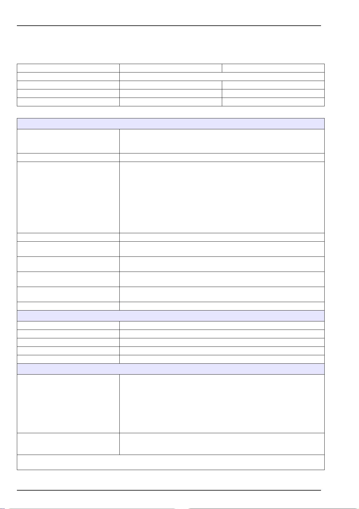
Material Safety Data Sheets (MSDS)
13.5 Sodium hexafluorosilicate
Name:
SODIUM HEXAFLUOROSILICATE (sodium fluorosilicate, disodium hexafluorosilicate disodique)
Formula: Na
Hazard class: 6.1 No. UN: 2674
CAS N° 16893-85-9
White granular powder
Density (20 °C) approx. 2,7 g cm
Slightly soluble in water (6g 1-1 to 20°C)
FIRE AND EXPLOSION HAZARD When heated to decomposition it may emit hydrogen fluoride.
HEALTH HAZARD Classification of risk - toxic.
Avoid contact with skin.
Avoid contact with eyes.
Keep locked up.
Keep out of reach of children.
Toxic by ingestion and skin contact
Toxic by inhalation
Irritating to skin and eyes, may cause damage if exposure is prolonged.
Occupational exposure standard, long term exposure limit (8h TWA) 2,5 mg m
SAFETY PRECAUTIONS - FIRST AID If the casualty feels unwell, seek medical advice and show label where possible.
EYES Rinse immediately and thoroughly with water for at least 10 minutes. Obtain
medical attention.
LUNGS Remove from exposure, rest and keep warm. In severe cases, or if exposure has
been great obtain medical attention.
MOUTH Wash out mouth thoroughly with water and give plenty of water to drink. Obtain
medical attention.
SKIN Wash skin thoroughly with water and give plenty of water to drink. Obtain medical
attention.
CHEMICAL HAZARD AND STABILITY Contact with acids liberates toxic gas.
PROTECTIVE MEASURES (as appropriate to quantity handled)
RESPIRATOR Dust respirator.
VENTILATION Extraction hood.
GLOVES Rubber or plastic.
EYE PROTECTION Goggles or face shield.
OTHERS MEASURES Plastic apron, sleeves, boots - if handling large quantities.
PRECAUTIONS Wear appropriate protective clothing.
Mix with sand, transfer carefully to canister and arrange removal by disposal
company. Wash site of spillage thoroughly with water and detergent.
For large spillages liquids should be contained with sand or earth and both liquids
and solids transferred to salvage canisters. Any residues should be treated as for
small spillages.
If material has entered surface drains it may be necessary to inform Local
Authorities, including fire services flammable.
WASTE DISPOSAL Dispose in safe manner consistent with Local Authorities or national chemical
Waste Regulation. For guidelines for disposal in the UK consult the requirements of
the Control of Pollution (special wastes) regulations (1980 SI 1709).
The information in this sheet is believed to be correct at the time of printing. The details should be reviewed periodically and
should be checked for special uses.
SiF
2
6
PHYSICAL PROPERTIES
SPILLAGE HANDLING
-3
-3
88
Page 91
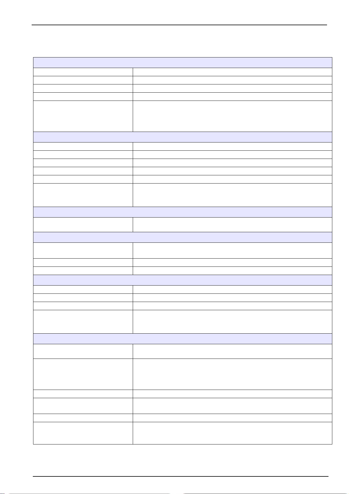
Material Safety Data Sheets (MSDS)
13.6 Ferrous ammonium sulfate hexahydrate
PRODUCT IDENTIFICATION
PRODUCT NAME FERROUS AMMONIUM SULPHATE HEXAHYDRATE
CAS No. (CE) 7783-85-9 233-151-8
FORMULA (NH4)
MOLECULAR WEIGHT 392,14 AMU
ALTERNATIVE NAMES Ferrous ammonium sulfate hexahydrate
FORM Solid
COULOUR Greenish blue
ODOUR Nil
MELTING POINT 100°C
DENSITY 1.86 g/cm
FIRE AND EXPLOSION HAZARD Non-combustible.
SPECIFIC ENVIRONMENTAL AND
HEALTH HAZARDS
EYES - SKIN Flush copiously with water.
RESPIRATORY TRACT Avoid continued exposure, breathe in fresh air; seek medical attention.
IF SWALLOWED Drink plenty of water, provoke vomiting, and seek medical advice.
STABILITY Conditions to avoid - high temperatures
CONDITIONS TO AVOID Sensitive to air, sensitive to light.
PRODUCTS TO AVOID Powerful oxidizing agents and acids.
DANGEROUS DECOMPOSITION
PRODUCTS
HANDLING Safe Handling Instructions: Do not breathe the dust. Avoid contact with the eyes,
EXPOSURE LIMITS UK:
BREATHING EQUIPMENT Use dust-masks or over-pressure breathing gear if dust formation is likely.
GLOVES Essential.
EYE PROTECTION Protective glasses/goggles are essential.
OTHER Wear protective clothing and work in a well-ventilated area.
Fe(SO4)2, 6H2O
2
Ammonium ferrous sulfate, hexahydrate
Iron ammonium sulfate hydrate
Sulfuric acid, ammonium iron (2+) salt, hexahydrate
PHYSICAL PROPERTIES
3
Likelihood of dangerous vapors being given off if close to a fire.
In fire situations it may form nitrogen oxides and sulphur oxides.
HEALTH RISKS
Irritant for the eyes, respiratory tract and skin.
SAFETY MEASURES
Remove any contaminated clothing
CHEMICAL RISKS AND STABILITY
Iron oxides
Ammonia
Sulphur oxides
PREVENTIVE MEASURES
skin or clothing. Avoid prolonged or repeated exposures.
Source - category - value
OEL - LTEL - 1 mg (Fe)/m
OEL - STEL - 2 mg (Fe)/m
Wear chemical resistant gloves (nitrile rubber, NBR).
Remove any contaminated clothing and wash hands thoroughly after working with
the product.
3
3
89
Page 92
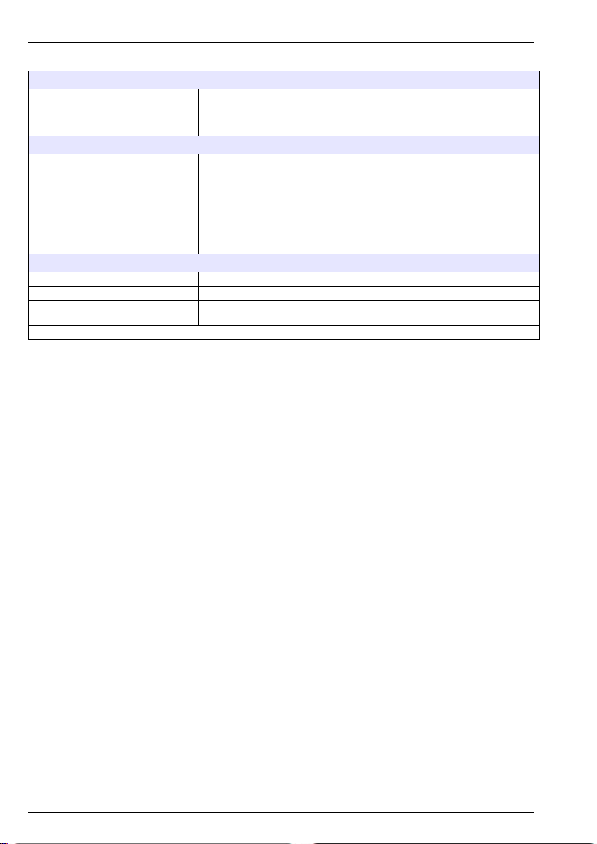
Material Safety Data Sheets (MSDS)
DISPOSAL MEASURES
Contact a specialist waste disposal organization where disposal of this product is
required. Dissolve, or mix, the product with a combustible solvent and burn in a
chemical incinerator fitted with post-combustion and scrubber systems. Observe all
applicable local, national and international environmental regulations.
FIRST AID MEASURES
FOLLOWING INHALATION In the event of inhalation, seek clean air. Where breathing has stopped, apply
artificial respiration. Where breathing is difficult, give oxygen.
FOLLOWING CONTACT WITH SKIN In the event of skin contact, wash the skin immediately using soap and plenty of
water.
FOLLOWING CONTACT WITH THE
EYE
FOLLOWING INGESTION (IF
SWALLOWED)
SUTABLE EXTINGUISHERS Water spray. Carbon dioxide, dry chemical powder or suitable foam.
SPECIAL RISKS Specific Danger(s): Gives off toxic fumes if burnt.
SPECIAL PROTECTIVE EQUIPMENT
NEEDED FOR FIRE FIGHTING
The information contained in this document is reviewed at regular intervals and checked for special cases.
In the event of contact with the eyes, rinse out immediately with plenty of water for
at least 15 minutes.
If swallowed, rinse out the mouth with water if the patient is still conscious. Call
medical assistance.
FIRE FIGHTING - EXTINCTION METHODS
Wear individual breathing apparatus and protective clothing to prevent any contact
with the eyes or skin.
90
Page 93
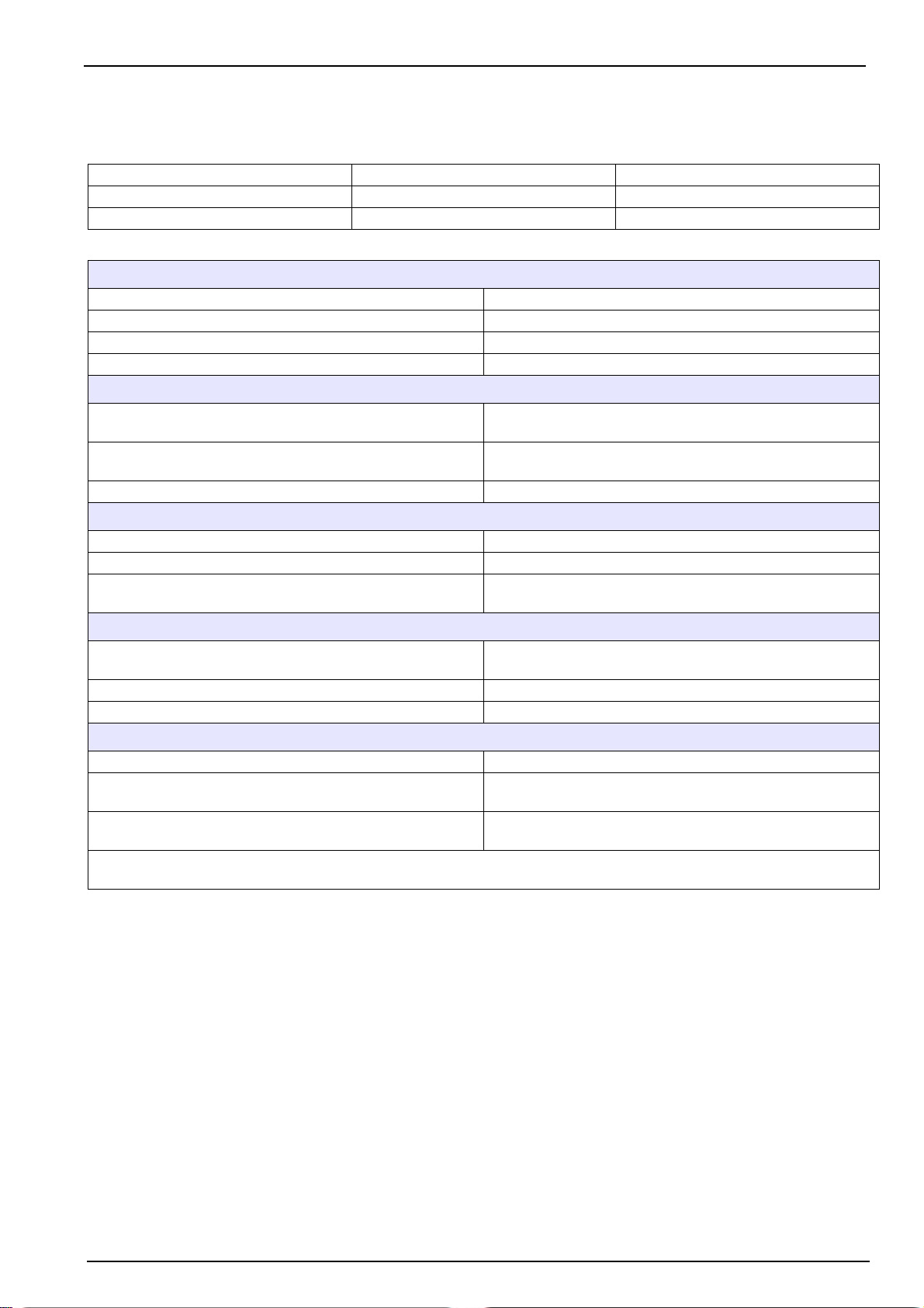
Material Safety Data Sheets (MSDS)
13.7Sodium molybdate dihydrate
Name:
SODIUM MOLYBDATE DIHYDRATE Formula: Na
CAS N° 10102-40-6
MELTING POINT 687°C
SOLUBILITY IN WATER 840 g/L
FIRE AND EXPLOSION RISK No information available
HEALTH RISKS Not hazardous according to Directive 67/548/EEC
EYES Rinse immediately with plenty of water, keeping the eyelids
LUNGS In case of inhalation, remove from exposure and move to
INGESTION Drink plenty of water. If feeling unwell seek medical aid
CHEMICAL DANGER AND STABILITY
STABILITY Stable
SPECIFIC RISKS No information available
DISPOSAL Observe all federal, state, and local environmental regulations
RESPIRITORY Wear appropriate breathing apparatus due to the formation of
GLOVES Not necessary
EYES Wear appropriate safety goggles
MEASURES TO TAKE IN CASE OF ACCIDENTAL SPILLAGE
PERSONAL Avoid inhalation of any dust
ENVIRONMENT Do not dispose of in any standard waste disposal systems
CLEANING Vacuum or sweep up material and place into a suitable
The information listed above must be reviewed periodically and should not be considered a substitute for the MSDS for this
product.
MoO4.2H2O
2
PHYSICAL PROPERTIES
SECURITY MEASURES
open as much as possible
fresh air immediately.
for disposal of chemical products
PERSONAL PROTECTION
dust
such as sinks or sewers
disposal container. Avoid generating dusty conditions.
91
Page 94
Material Safety Data Sheets (MSDS)
13.8 Reagent R1A
PRODUCT AND COMPANY IDENTIFICATION
SUBSTANCE Product code :R1A
Name of product: 9210 R1A Reagent
COMPOSITION / INFORMATION ABOUT THE COMPONENTS
CHEMICAL PROPERTIES Preparation
HAZARDOUS COMPONENTS
CAS NUMBER SOLUTION QUANTITY CLASSIFICATION
213-653-7
7697-37-2
Causes severe irritation and burns. Harmful if swallowed. Avoid breathing vapor or dust. Use with adequate ventilation. Avoid
contact with eyes, skin, and clothes. Wash thoroughly after handling. Keep container closed.
CHRONIC EXPOSURE Long-term exposure to concentrated vapors may cause
AGGRAVATION OF PRE-EXISTING CONDITIONS Persons with pre-existing skin disorders, eye disease, or
FIRE Not combustible, but substance is a strong oxidizer and its
EXPLOSION Reacts explosively with combustible organic or readily
FIRE EXTINGUISHING MEDIA Water spray may be used to keep fire exposed containers
SPECIAL INFORMATION Increases the flammability of combustible, organic and readily
Ventilate area of leak or spill. Wear appropriate personal protective equipment.
Keep unnecessary and unprotected personnel from entering. Contain and recover liquid when possible. Neutralize with
alkaline material (soda ash, lime), then absorb with an inert material (e.g. vermiculite, dry sand, earth), and place in a chemical
waste container. Do not use combustible materials, such as sawdust.
Store in a cool, dry, ventilated storage area with acid resistant floors and good drainage. Protect from physical damage. Keep
out of direct sunlight and away from heat, water, and incompatible materials. Do not wash out container and use it for other
purposes. When diluting, the acid should always be added slowly to water and in small amounts. Never use hot water and
never add water to the acid. Water added to acid can cause uncontrolled boiling and splashing. Containers of this material
may be hazardous when empty since they retain product residues (vapors, liquid); observe all warnings and precautions listed
for the product.
Water
Nitric acid
90%
10% Yes
IDENTIFICATION OF HAZARDS
FIRST AID
erosion of teeth and lung damage. Long-term exposures
seldom occur due to the corrosive properties of the acid.
cardiopulmonary diseases may be more susceptible to the
effects of this substance.
FIRE FIGHTING MEASURES
heat of reaction with reducing agents or combustibles may
cause ignition. Can react with metals to release flammable
hydrogen gas.
oxidizable materials such as: alcohols, turpentine, charcoal,
organic refuse, metal powder, hydrogen sulfide, etc. Reacts
with most metals to release hydrogen gas which can form
explosive mixtures with air.
cool. Do not get water inside container.
oxidizable materials. In the event of a fire, wear full protective
clothing and NIOSH-approved self-contained breathing
apparatus with full facepiece operated in the pressure
demand or other positive pressure mode.
MEASURES IN CASE OF SPILLAGE
HANDLING AND STORAGE
92
Page 95
Material Safety Data Sheets (MSDS)
EXPOSURE CONTROLS / INDIVIDUAL PROTECTION
RESPIRATORY PROTECTION A system of local and/or general exhaust is recommended to
keep employee exposures below the Airborne Exposure
Limits. Local exhaust ventilation is generally preferred
because it can control the emissions of the contaminant at its
source, preventing dispersion of it into the general work area.
SKIN PROTECTION Wear impervious protective clothing, including boots, gloves,
lab coat, apron or coveralls, as appropriate, to prevent skin
contact.
EYE PROTECTION Safety glasses recommended.
PHYSICAL AND CHEMICAL PROPERTIES
APPEARANCE Liquid.
COLOR Colorless
ODOR Suffocating, acrid.
PH 1.0
STABILITY AND REACTIVITY
CONDITIONS TO AVOID Stable under ordinary conditions of use and storage.
Containers may burst when heated.
TOXICOLOGICAL INFORMATION
Inhalation rat LC50: 244 ppm (NO2)/30M; Investigated as a
NITRIC ACID
ECOLOGICAL INFORMATION
ENVIRONMENTAL TOXICITY No information found
DISPOSAL CONSIDERATIONS
PRODUCT
PACKAGING
TRANSPORT INFORMATION
Not subject to transport provisions.
REGULATORY INFORMATION
Labelling to EEC directives
OTHER INFORMATION
Updated version : January 2009 Issue A.
mutagen, reproductive effector. Oral (human) LDLo: 430
mg/kg.
There are as yet no uniform regulations concerning the
disposal of chemicals and their residues within the European
Union.
The chemicals and their residues must be considered as
special waste; their disposal is regulated by each EEC
member state. We advise you to contact the competent
authorities (administration or specialist waste disposal
companies) that will inform you of the disposal measures to
take.
Disposal in accordance with prevailing legislation.
Contaminated containers must be processed in the same
manner as the chemical itself. Unless specifically regulated,
non-contaminated containers may be disposed of as
household waste, or be recycled.
93
Page 96
Material Safety Data Sheets (MSDS)
13.9 Reagent R1M
PRODUCT AND COMPANY IDENTIFICATION
SUBSTANCE Product code :R1M
Name of product: 9210 R1M Reagent
COMPOSITION / INFORMATION ABOUT THE COMPONENTS
CHEMICAL PROPERTIES Preparation
HAZARDOUS COMPONENTS
CAS NUMBER SOLUTION QUANTITY CLASSIFICATION
213-653-7
7758-02-3
INHALATION Vapors and mists cause irritation to the respiratory tract.
INGESTION May cause gastrointestinal irritation with nausea, vomiting
SKIN CONTACT Causes irritation and burns to the skin.
EYE CONTACT Vapors cause irritation. Splashes cause severe pain, eye
CHRONIC EXPOSURE Repeated exposure may cause damage to the tissues of the
AGGRAVATION OF PRE-EXISTING CONDITIONS Persons with pre-existing eye disorders or impaired
EYE CONTACT Irrigate thoroughly with water. If discomfort persists obtain
INHALATION Remove from exposure.
SKIN CONTACT Wash off thoroughly with soap and water.
INGESTION Wash out mouth thoroughly with water. In severe cases obtain
SPECIAL RISKS Not readily combustible.
Wear appropriate protective clothing.
If local regulations permit, mop up with plenty of water and run to waste, diluting greatly with running water. Otherwise transfer
to container and arrange removal by disposal company. Wash site of spillage thoroughly with detergent and water.
For large spillages liquids should be contained with sand or earth and both liquids and solids transferred to salvage
containers.
Any residues should be treated as for small spillages.
HANDLING Wash thoroughly after handling. Avoid contact with eyes, skin,
STORAGE Store in a tightly closed container.
Water
Sodium Molybdate Dihydrate
IDENTIFICATION OF HAZARDS
FIRST AID
FIRE FIGHTING MEASURES
MEASURES IN CASE OF SPILLAGE
HANDLING AND STORAGE
94%
<5% Yes
and diarrhea.
damage, and permanent blindness.
mucous membranes, upper respiratory tract, eyes and skin.
respiratory function may be more susceptible to the effects of
this material.
medical attention.
medical attention.
and clothing.. Avoid ingestion and inhalation. Wash clothing
before reuse.
94
Page 97
Material Safety Data Sheets (MSDS)
EXPOSURE CONTROLS / INDIVIDUAL PROTECTION
RESPIRATORY PROTECTION If the exposure limit is exceeded and engineering controls are
not feasible, a full facepiece respirator may be worn.
HAND PROTECTION Wear latex gloves.
EYE PROTECTION Safety glasses recommended.
HYGIENE MEASURES Wash hands after working with substance.
PHYSICAL AND CHEMICAL PROPERTIES
APPEARANCE Liquid.
COLOR Colorless
ODOR
PH ~7
STABILITY AND REACTIVITY
CONDITIONS TO AVOID Stable under ordinary conditions of use and storage
TOXICOLOGICAL INFORMATION
After eye contact May irritate.
After skin contact May irritate.
Hazardous properties cannot be excluded but unlikely when handled appropriately. The product should be handled with the
care usual when dealing with chemicals.
ECOLOGICAL INFORMATION
ENVIRONMENTAL TOXICITY No information found
OTHER ECOLOGY-RELATED INFORMATION
DISPOSAL CONSIDERATIONS
PRODUCT
PACKAGING
TRANSPORT INFORMATION
Not subject to transport provisions.
REGULATORY INFORMATION
Labelling to EEC directives
OTHER INFORMATION
Updated version : January 2009 Issue A.
In the event of appropriate handling and use, there is no risk
of ecological problems.
There are as yet no uniform regulations concerning the
disposal of chemicals and their residues within the European
Union.
The chemicals and their residues must be considered as
special waste; their disposal is regulated by each EEC
member state. We advise you to contact the competent
authorities (administration or specialist waste disposal
companies) that will inform you of the disposal measures to
take.
Disposal in accordance with prevailing legislation.
Contaminated containers must be processed in the same
manner as the chemical itself. Unless specifically regulated,
non-contaminated containers may be disposed of as
household waste, or be recycled.
95
Page 98
Material Safety Data Sheets (MSDS)
13.10Reagent R2
PRODUCT AND COMPANY IDENTIFICATION
SUBSTANCE Product code: R2
Name of product: 9210 R2 Reagent
SUPPLIER Manufacturer Name: HACH SAS
Address: 29 rue de Bures, 14670 Troarm
Phone : (33) 02.31.15.37.10
Fax N° : (33) 02.31.15.37.30
Emergency : (33) 02.31.15.37.35 (Unit of production)
: (33) 01.45.42.59.59 (N° ORFILA)
COMPOSITION / INFORMATION ABOUT THE COMPONENTS
CHEMICAL PROPERTIES Preparation
HAZARDOUS COMPONENTS
CAS NUMBER SOLUTION QUANTITY CLASSIFICATION
213-653-7
6153-56-6
Injurious on contact with skin or by ingestion
SKIN CONTACT Rinse affected area with plenty of water. Remove
EYE CONTACT Immediately flush eyes with plenty of water with eyelids open
IF SWALLOWED IN LARGE QUANTITIES Give plenty of water to drink. In case of vomiting, take medical
EXTINGUISHING MEANS Adapt the extinguishing agent to the products stored in the
SPECIFIC HAZARDS Non combustible. Risk of forming hydrogen if in contact with
PRECAUTIONS FOR PEOPLE Avoid contact with skin and eyes
ENVIRONMENT PROTECTION Do not pour in sewers or rivers
CLEANING Collect in specific containers. Clean soiled materials
STORAGE RECOMMENDATIONS Store in hermetically sealed containers
RESPIRATORY PROTECTION Required if steam / aerosol
HAND PROTECTION Wear nitrile gloves
EYE PROTECTION Safety glasses are required
HYGIENE MEASURES Wash hands after contact
FORM Liquid
COLOR Colorless
ODOR Odorless
pH < 1
Water
Oxalic acid
IDENTIFICATION OF HAZARDS
FIRE FIGHTING MEASURES
MEASURES IN CASE OF SPILLAGE
HANDLING AND STORAGE
EXPOSURE CONTROLS / INDIVIDUAL PROTECTION
PHYSICAL AND CHEMICAL PROPERTIES
95%
5% Xn ; R21/22
FIRST AID
contaminated clothing.
advice.
immediate vicinity
light metals
96
Page 99
Material Safety Data Sheets (MSDS)
STABILITY AND REACTIVITY
CONDITIONS TO BE AVOIDED Strong heating
SUBSTANCES TO BE AVOIDED Bases
DANGEROUS BY-PRODUCTS No available information
TOXICOLOGICAL INFORMATION
ACUTE TOXICITY DL50 (oral, rat): 7500 mg/Kg
IN THE EVENT OF SKIN CONTACT Slight irritation
IN THE EVENT OF EYE CONTACT Slight irritation
IF SWALLOWED IN LARGE QUANTITIES Injurious
ECOLOGICAL INFORMATION
ECOTOXIC Biologic: Fish CL50: 325 mg/l (anhydrous liquid)
OTHER ECOLOGY-RELATED INFORMATION Damage:
DCO: 0.18 g/g (compared to the pure substance)
DThO: 0.18 g/g (compared to the pure substance)
DBO: 0.16 g/g (compared to the pure substance)
Do not pour in sewer or in the rivers.
DISPOSAL CONSIDERATIONS
PRODUCT There are as yet no uniform regulations concerning the
disposal of chemicals and their residues within the European
Union.
The chemicals and their residues must be considered as
special waste; their disposal is regulated by each EEC
member state.
We advise you to contact the competent authorities
(administration or specialist waste disposal companies) that
will inform you of the disposal measures to take
PACKAGING Disposal in accordance with prevailing legislation.
Contaminated containers must be processed in the same
manner as the chemical itself.
Unless specifically regulated, non-contaminated containers
may be disposed of as household waste, or be recycled
TRANSPORT INFORMATION
Not subject to transport provisions
REGULAR INFORMATION
LABELLING TO EEC DIRECTIVES
HAZARDOUS PRODUCT IDENTIFICATION
Xn Injurious
" R " Phrases
" S " Phrases
Updated version: November 2005 Issue A
R21/22
S36/37
OTHER INFORMATION
Injurious in contact with skin
or if ingested
Wear protective clothes and
appropriate gloves
97
Page 100
Material Safety Data Sheets (MSDS)
13.11Reagent R3
PRODUCT AND COMPANY IDENTIFICATION
SUBSTANCE Product code: R3
Name of product: 9210 R3 Reagent
SUPPLIER Manufacturer Name: HACH SAS
Address: 29 rue de Bures, 14670 Troarm
Phone : (33) 02.31.15.37.10
Fax N° : (33) 02.31.15.37.30
Emergency : (33) 02.31.15.37.35 (Unit of production)
: (33) 01.45.42.59.59 (N° ORFILA)
COMPOSITION / INFORMATION ABOUT THE COMPONENTS
CHEMICAL PROPERTIES Preparation
HAZARDOUS COMPONENTS
CAS NUMBER SOLUTION QUANTITY CLASIFICATION
213-653-7
7783-85-9
7664-93-9
Product not considered as dangerous according to the 67/548/CEE directive
SKIN CONTACT Rinse affected area with plenty of water. Remove
EYE CONTACT Immediately flush eyes with plenty of water with eyelids open
IF SWALLOWED IN LARGE QUANTITIES Give plenty of water to drink. In case of indisposition, take
EXTINGUISHING MEANS Adapt the extinguishing agent to the products stored in the
SPECIFIC HAZARDS Non combustible. Risk of forming hydrogen if in contact with
PRECAUTIONS FOR PEOPLE Avoid contact with skin and eyes
ENVIRONMENT PROTECTION Do not pour in sewers or rivers
CLEANING Collect in specific containers. Clean soiled materials
PRECAUTIONS TO TAKE Avoid contact with metals
USEAGE ADVICE Respect conditions of use
STORAGE RECOMMENDATIONS Store in hermetically sealed containers
RESPIRATORY PROTECTION Required if steam / aerosol
HAND PROTECTION Wear nitrile gloves
EYE PROTECTION Safety glasses are required
OTHER PROTECTION Acid-proof clothing
HYGIENE MEASURES Wash hands after contact
Water
Ammonium iron III sulfates
Sulfuric acid
IDENTIFICATION OF HAZARDS
FIRE FIGHTING MEASURES
MEASURES IN CASE OF SPILLAGE
HANDLING AND STORAGE
EXPOSURE CONTROLS / INDIVIDUAL PROTECTION
96%
2%
2% C; R35; S26 -30 - 45
FIRST AID
contaminated clothing. Swab with polyethylene glycol 400
for 10 minutes. Get medical aid if necessary
medical advice. Do not try to neutralize
immediate vicinity
light metals
98
 Loading...