

Page 1
product pic here
Administrator’s Guide
for the VSX Series
May, 2006 Edition
3725-20235-010/A
VSX Version 8.5
Version 8.5
Page 2

Trademark Information
Polycom®, the Polycom logo design, SoundStation®, SoundStation VTX 1000®, ViaVideo®, ViewStation®, and
Vortex® are registered trademarks of Polycom, Inc. Conference Composer™, Global Management System™,
ImageShare™, Instructor RP™, iPower™, MGC™, PathNavigator™, People+Content™, PowerCam™, Pro-Motion™,
2
QSX™, ReadiManager™, Siren™, StereoSurround™, V
IU™, Visual Concert™, VS4000™, and VSX™ are
trademarks of Polycom, Inc. in the United States and various other countries. All other trademarks are the property of
their respective owners.
Patent Information
The accompanying product is protected by one or more U.S. and foreign patents and/or pending patent applications
held by Polycom, Inc.
© 2006 Polycom, Inc. All rights reserved.
Polycom Inc.
4750 Willow Road
Pleasanton, CA 94588-2708
USA
No part of this document may be reproduced or transmitted in any form or by any means, electronic or mechanical, for
any purpose, without the express written permission of Polycom, Inc. Under the law, reproducing includes translating
into another language or format.
As between the parties, Polycom, Inc. retains title to, and ownership of, all proprietary rights with respect to the software
contained within its products. The software is protected by United States copyright laws and international treaty
provision. Therefore, you must treat the software like any other copyrighted material (e.g. a book or sound recording).
Every effort has been made to ensure that the information in this manual is accurate. Polycom, Inc. is not responsible
for printing or clerical errors. Information in this document is subject to change without notice.
Page 3

About This Guide
The Administrator’s Guide for the VSX Series is for administrators who need to
configure, customize, manage, and troubleshoot VSX™ systems. The guide
covers the VSX 3000, VSX 3000A, VSX 5000, VSX 6000, VSX 6000A, VSX 7000,
VSX 7000s, VSX 7000e, and VSX 8000 systems.
The following related documents for VSX systems are available at
www.polycom.com/videodocumentation:
• Setting Up the System, which describes how to set up the hardware
• Getting Started Guide for the VSX Series, which describes how to perform
video conferencing tasks
• Setup Sheets for your optional hardware
• Release Notes
• Integrator’s Reference Manual for the VSX Series, which provides cable
information and API command descriptions
For support or service, please contact your Polycom® distributor or go to
Polycom Support at www.polycom.com/support.
Polycom recommends that you record the serial number and option key of
your VSX system here for future reference. The serial number for the system is
printed on the unit.
System Serial Number: ____________________________________________
Option Key: ____________________________________________________
iii
Page 4

Administrator’s Guide for the VSX Series
iv
Page 5

Contents
1 Introducing the VSX Series . . . . . . . . . . . . . . . . . . . . . . . . 1-1
VSX Models . . . . . . . . . . . . . . . . . . . . . . . . . . . . . . . . . . . . . . . . . . . . . . . . . . . . . . . . . . . . . . . . . . . 1-1
Key Features . . . . . . . . . . . . . . . . . . . . . . . . . . . . . . . . . . . . . . . . . . . . . . . . . . . . . . . . . . . . . . . . . . 1-9
VSX 3000 and VSX 3000A Desktop Systems . . . . . . . . . . . . . . . . . . . . . . . . . . . . . . . . . . . . 1-2
VSX 5000 Set-top System . . . . . . . . . . . . . . . . . . . . . . . . . . . . . . . . . . . . . . . . . . . . . . . . . . . . 1-3
VSX 6000 and VSX 6000A Set-top Systems . . . . . . . . . . . . . . . . . . . . . . . . . . . . . . . . . . . . . 1-4
VSX 7000 and VSX 7000s Set-top Systems . . . . . . . . . . . . . . . . . . . . . . . . . . . . . . . . . . . . . . 1-5
VSX 7000e Component System . . . . . . . . . . . . . . . . . . . . . . . . . . . . . . . . . . . . . . . . . . . . . . . 1-6
VSX 8000 Component System . . . . . . . . . . . . . . . . . . . . . . . . . . . . . . . . . . . . . . . . . . . . . . . . 1-8
Breakthrough Video Quality . . . . . . . . . . . . . . . . . . . . . . . . . . . . . . . . . . . . . . . . . . . . . . . . . 1-9
Industry-Leading Audio Quality . . . . . . . . . . . . . . . . . . . . . . . . . . . . . . . . . . . . . . . . . . . . 1-10
Rich Conference Experience . . . . . . . . . . . . . . . . . . . . . . . . . . . . . . . . . . . . . . . . . . . . . . . . 1-10
Enhanced User Experience . . . . . . . . . . . . . . . . . . . . . . . . . . . . . . . . . . . . . . . . . . . . . . . . . 1-11
Easy Installation . . . . . . . . . . . . . . . . . . . . . . . . . . . . . . . . . . . . . . . . . . . . . . . . . . . . . . . . . . 1-11
Security . . . . . . . . . . . . . . . . . . . . . . . . . . . . . . . . . . . . . . . . . . . . . . . . . . . . . . . . . . . . . . . . . . 1-12
Remote Management . . . . . . . . . . . . . . . . . . . . . . . . . . . . . . . . . . . . . . . . . . . . . . . . . . . . . . 1-12
2 Setting Up Your System Hardware . . . . . . . . . . . . . . . . . . . 2-1
System Back Panel Views . . . . . . . . . . . . . . . . . . . . . . . . . . . . . . . . . . . . . . . . . . . . . . . . . . . . . . . 2-1
VSX 3000 and VSX 3000A Connector Panel . . . . . . . . . . . . . . . . . . . . . . . . . . . . . . . . . . . . 2-1
VSX 5000 Back Panel . . . . . . . . . . . . . . . . . . . . . . . . . . . . . . . . . . . . . . . . . . . . . . . . . . . . . . . 2-2
VSX 6000 Back Panel . . . . . . . . . . . . . . . . . . . . . . . . . . . . . . . . . . . . . . . . . . . . . . . . . . . . . . . 2-3
VSX 6000A Back Panel . . . . . . . . . . . . . . . . . . . . . . . . . . . . . . . . . . . . . . . . . . . . . . . . . . . . . . 2-4
VSX 7000 Back Panel . . . . . . . . . . . . . . . . . . . . . . . . . . . . . . . . . . . . . . . . . . . . . . . . . . . . . . . 2-5
VSX 7000s Back Panel . . . . . . . . . . . . . . . . . . . . . . . . . . . . . . . . . . . . . . . . . . . . . . . . . . . . . . . 2-6
VSX 7000e Back Panel . . . . . . . . . . . . . . . . . . . . . . . . . . . . . . . . . . . . . . . . . . . . . . . . . . . . . . . 2-7
VSX 8000 Back Panel . . . . . . . . . . . . . . . . . . . . . . . . . . . . . . . . . . . . . . . . . . . . . . . . . . . . . . . 2-8
Positioning the System . . . . . . . . . . . . . . . . . . . . . . . . . . . . . . . . . . . . . . . . . . . . . . . . . . . . . . . . . . 2-9
Positioning Desktop Systems . . . . . . . . . . . . . . . . . . . . . . . . . . . . . . . . . . . . . . . . . . . . . . . . 2-9
Positioning Set-top Systems . . . . . . . . . . . . . . . . . . . . . . . . . . . . . . . . . . . . . . . . . . . . . . . . 2-10
Positioning Component Systems . . . . . . . . . . . . . . . . . . . . . . . . . . . . . . . . . . . . . . . . . . . . 2-11
Connecting to the LAN . . . . . . . . . . . . . . . . . . . . . . . . . . . . . . . . . . . . . . . . . . . . . . . . . . . . . . . . 2-11
Connecting to Other Networks . . . . . . . . . . . . . . . . . . . . . . . . . . . . . . . . . . . . . . . . . . . . . . . . . . 2-12
Connecting Desktop Systems to the ISDN BRI Network . . . . . . . . . . . . . . . . . . . . . . . . 2-13
Connecting Set-top and Component Systems to ISDN or Other Networks . . . . . . . . 2-14
v
Page 6

Administrator’s Guide for the VSX Series
Connecting Cameras . . . . . . . . . . . . . . . . . . . . . . . . . . . . . . . . . . . . . . . . . . . . . . . . . . . . . . . . . . 2-15
Connecting Document Cameras to Desktop Systems . . . . . . . . . . . . . . . . . . . . . . . . . . . 2-15
Connecting Cameras to Set-top Systems . . . . . . . . . . . . . . . . . . . . . . . . . . . . . . . . . . . . . . 2-15
Connecting Cameras to Component Systems . . . . . . . . . . . . . . . . . . . . . . . . . . . . . . . . . 2-15
Using a Desktop System as the Monitor for a Computer . . . . . . . . . . . . . . . . . . . . . . . . . . . . 2-16
Connecting Monitors and Projectors . . . . . . . . . . . . . . . . . . . . . . . . . . . . . . . . . . . . . . . . . . . . . 2-17
Connecting Monitors to Set-Top Systems . . . . . . . . . . . . . . . . . . . . . . . . . . . . . . . . . . . . . 2-17
Additional TV Monitor . . . . . . . . . . . . . . . . . . . . . . . . . . . . . . . . . . . . . . . . . . . . . . . . 2-17
VGA Monitor or Projector . . . . . . . . . . . . . . . . . . . . . . . . . . . . . . . . . . . . . . . . . . . . . . 2-18
Connecting Monitors to Component Systems . . . . . . . . . . . . . . . . . . . . . . . . . . . . . . . . . 2-18
Additional TV Monitor . . . . . . . . . . . . . . . . . . . . . . . . . . . . . . . . . . . . . . . . . . . . . . . . 2-18
VGA Monitor or Projector . . . . . . . . . . . . . . . . . . . . . . . . . . . . . . . . . . . . . . . . . . . . . . 2-18
Connecting Microphones or a SoundStation VTX 1000 . . . . . . . . . . . . . . . . . . . . . . . . . . . . . 2-19
About Polycom Microphones and the SoundStation VTX 1000 . . . . . . . . . . . . . . . . . . 2-19
Connecting Polycom Microphones to Set-Top or Component Systems . . . . . . . . . . . . 2-20
Placing Polycom Microphones to Send Stereo from Your Site . . . . . . . . . . . . . . . . . . . 2-22
Connecting a SoundStation VTX 1000 to a Set-top or Component System . . . . . . . . . 2-24
Placing a SoundStation VTX 1000 Phone to Send Stereo from Your Site . . . . . . . . . . . 2-25
Connecting Powered Microphones or a Mixer to a VSX 8000
Component System . . . . . . . . . . . . . . . . . . . . . . . . . . . . . . . . . . . . . . . . . . . . . . . . . . . . . . . . 2-26
Connecting Speakers . . . . . . . . . . . . . . . . . . . . . . . . . . . . . . . . . . . . . . . . . . . . . . . . . . . . . . . . . . 2-26
Connecting Speakers or Headphones to Desktop Systems . . . . . . . . . . . . . . . . . . . . . . 2-26
Connecting Speakers to Set-top Systems . . . . . . . . . . . . . . . . . . . . . . . . . . . . . . . . . . . . . . 2-26
Connecting Speakers to Component Systems . . . . . . . . . . . . . . . . . . . . . . . . . . . . . . . . . 2-26
Placing Speakers to Play Stereo from Far Sites . . . . . . . . . . . . . . . . . . . . . . . . . . . . . . . . . 2-27
Connecting Content Sharing Equipment . . . . . . . . . . . . . . . . . . . . . . . . . . . . . . . . . . . . . . . . . 2-28
Connecting VCR/DVDs . . . . . . . . . . . . . . . . . . . . . . . . . . . . . . . . . . . . . . . . . . . . . . . . . . . 2-28
Connecting a Visual Concert VSX to Set-top Systems . . . . . . . . . . . . . . . . . . . . . . . . . . . 2-29
Connecting an ImageShare II to Component Systems . . . . . . . . . . . . . . . . . . . . . . . . . . 2-31
Connecting Computers to Component Systems . . . . . . . . . . . . . . . . . . . . . . . . . . . . . . . 2-31
Connecting Control and Accessibility Equipment . . . . . . . . . . . . . . . . . . . . . . . . . . . . . . . . . . 2-32
Connecting Closed Captioning Equipment . . . . . . . . . . . . . . . . . . . . . . . . . . . . . . . . . . . 2-32
Connecting Touch-Panel Controls . . . . . . . . . . . . . . . . . . . . . . . . . . . . . . . . . . . . . . . . . . . 2-32
Connecting IR Sensors to VSX 8000 Systems . . . . . . . . . . . . . . . . . . . . . . . . . . . . . . . . . . 2-33
Powering On . . . . . . . . . . . . . . . . . . . . . . . . . . . . . . . . . . . . . . . . . . . . . . . . . . . . . . . . . . . . . . . . . 2-33
Powering On the VSX 3000 or VSX 3000A Desktop System . . . . . . . . . . . . . . . . . . . . . 2-33
Powering On Set-top and Component Systems . . . . . . . . . . . . . . . . . . . . . . . . . . . . . . . . 2-34
3 Configuring Network Use . . . . . . . . . . . . . . . . . . . . . . . . . 3-1
Getting the Network Ready . . . . . . . . . . . . . . . . . . . . . . . . . . . . . . . . . . . . . . . . . . . . . . . . . . . . . 3-1
Network Connectivity Checklist . . . . . . . . . . . . . . . . . . . . . . . . . . . . . . . . . . . . . . . . . . . . . . . . . 3-2
Configuring with the Setup Wizard . . . . . . . . . . . . . . . . . . . . . . . . . . . . . . . . . . . . . . . . . . . . . . . 3-3
Configuring LAN Properties . . . . . . . . . . . . . . . . . . . . . . . . . . . . . . . . . . . . . . . . . . . . . . . . . . . . . 3-4
Configuring IP Network Support . . . . . . . . . . . . . . . . . . . . . . . . . . . . . . . . . . . . . . . . . . . . . . . . . 3-6
Specifying H.323 Settings . . . . . . . . . . . . . . . . . . . . . . . . . . . . . . . . . . . . . . . . . . . . . . . . . . . 3-6
Configuring the System to Use a Gatekeeper . . . . . . . . . . . . . . . . . . . . . . . . . . . . . . . 3-7
Configuring Integration with Avaya Networks . . . . . . . . . . . . . . . . . . . . . . . . . . . . . 3-9
vi
Page 7

Contents
Configuring the System to Use a Gateway . . . . . . . . . . . . . . . . . . . . . . . . . . . . . . . . 3-10
Specifying SIP Settings . . . . . . . . . . . . . . . . . . . . . . . . . . . . . . . . . . . . . . . . . . . . . . . . . . . . . 3-12
Integration with Microsoft Live Communications Server (LCS) . . . . . . . . . . . . . . 3-13
Adding and Removing Microsoft LCS Contacts . . . . . . . . . . . . . . . . . . . . . . . . . . . 3-14
Specifying Quality of Service . . . . . . . . . . . . . . . . . . . . . . . . . . . . . . . . . . . . . . . . . . . . . . . 3-15
Configuring the System for Use with a Firewall or NAT . . . . . . . . . . . . . . . . . . . . . . . . 3-16
H.460 NAT Firewall Traversal . . . . . . . . . . . . . . . . . . . . . . . . . . . . . . . . . . . . . . . . . . 3-18
Configuring ISDN Support . . . . . . . . . . . . . . . . . . . . . . . . . . . . . . . . . . . . . . . . . . . . . . . . . . . . . 3-19
Configuring the BRI Network Interface . . . . . . . . . . . . . . . . . . . . . . . . . . . . . . . . . . . . . . 3-19
Configuring the PRI Network Interface . . . . . . . . . . . . . . . . . . . . . . . . . . . . . . . . . . . . . . 3-21
Configuring the Serial V.35/RS-449/RS-530 Network Interface . . . . . . . . . . . . . . . . . . 3-24
Configuring Telephony with the SoundStation VTX 1000 . . . . . . . . . . . . . . . . . . . . . . . 3-27
Configuring Call Preferences . . . . . . . . . . . . . . . . . . . . . . . . . . . . . . . . . . . . . . . . . . . . . . . . . . . 3-28
Configuring Dialing Order Settings . . . . . . . . . . . . . . . . . . . . . . . . . . . . . . . . . . . . . . . . . . 3-30
Configuring the Global Directory . . . . . . . . . . . . . . . . . . . . . . . . . . . . . . . . . . . . . . . . . . . . . . . 3-31
Configuring the Directory Server Settings . . . . . . . . . . . . . . . . . . . . . . . . . . . . . . . . . . . . 3-31
Setting the Dialing Rules . . . . . . . . . . . . . . . . . . . . . . . . . . . . . . . . . . . . . . . . . . . . . . . . . . . 3-32
Placing a Test Call . . . . . . . . . . . . . . . . . . . . . . . . . . . . . . . . . . . . . . . . . . . . . . . . . . . . . . . . . . . . . 3-33
Checking System Status . . . . . . . . . . . . . . . . . . . . . . . . . . . . . . . . . . . . . . . . . . . . . . . . . . . . . . . . 3-33
Keeping your Software Current . . . . . . . . . . . . . . . . . . . . . . . . . . . . . . . . . . . . . . . . . . . . . . . . . 3-34
4 Customizing the VSX System . . . . . . . . . . . . . . . . . . . . . . . 4-1
Designing Video Behaviors . . . . . . . . . . . . . . . . . . . . . . . . . . . . . . . . . . . . . . . . . . . . . . . . . . . . . . 4-1
Configuring Camera Settings and Video Quality Options . . . . . . . . . . . . . . . . . . . . . . . . 4-2
Configuring Automatic Camera Tracking . . . . . . . . . . . . . . . . . . . . . . . . . . . . . . . . . 4-4
Configuring Camera Presets . . . . . . . . . . . . . . . . . . . . . . . . . . . . . . . . . . . . . . . . . . . . . 4-5
Configuring Monitors . . . . . . . . . . . . . . . . . . . . . . . . . . . . . . . . . . . . . . . . . . . . . . . . . . . . . . 4-6
Using Dual Monitor Emulation . . . . . . . . . . . . . . . . . . . . . . . . . . . . . . . . . . . . . . . . . 4-11
Adjusting the Monitor’s Color Balance, Sharpness, and Brightness . . . . . . . . . . . 4-12
Preventing Monitor Burn-In . . . . . . . . . . . . . . . . . . . . . . . . . . . . . . . . . . . . . . . . . . . . 4-13
Configuring Content Display . . . . . . . . . . . . . . . . . . . . . . . . . . . . . . . . . . . . . . . . . . . . . . . 4-13
Configuring Content Display with People+Content IP . . . . . . . . . . . . . . . . . . . . . 4-14
Configuring Content Display with a Visual Concert VSX or ImageShare II . . . . 4-16
Configuring VCR/DVD Player Settings . . . . . . . . . . . . . . . . . . . . . . . . . . . . . . . . . . . . . . 4-18
Playing a Videotape or DVD . . . . . . . . . . . . . . . . . . . . . . . . . . . . . . . . . . . . . . . . . . . . 4-18
Recording a Call to Videotape or DVD . . . . . . . . . . . . . . . . . . . . . . . . . . . . . . . . . . . 4-18
Designing Audio Behaviors . . . . . . . . . . . . . . . . . . . . . . . . . . . . . . . . . . . . . . . . . . . . . . . . . . . . 4-20
Configuring General Audio Settings . . . . . . . . . . . . . . . . . . . . . . . . . . . . . . . . . . . . . . . . . 4-20
Configuring StereoSurround Settings . . . . . . . . . . . . . . . . . . . . . . . . . . . . . . . . . . . . . . . . 4-25
Configuring VSX Systems for a Polycom Vortex Mixer . . . . . . . . . . . . . . . . . . . . . . . . . 4-26
Configuring Microphones Connected to Audio Inputs . . . . . . . . . . . . . . . . . . . . . . . . . 4-27
Configuring Microphones Connected to Balanced Audio Inputs on a
VSX 8000 System . . . . . . . . . . . . . . . . . . . . . . . . . . . . . . . . . . . . . . . . . . . . . . . . . . . . . . . . . . 4-28
Configuring RS-232 Equipment . . . . . . . . . . . . . . . . . . . . . . . . . . . . . . . . . . . . . . . . . . . . . . . . . 4-29
Configuring for Use with a Touch Panel Control . . . . . . . . . . . . . . . . . . . . . . . . . . . . . . 4-29
Configuring for Use with a Modem . . . . . . . . . . . . . . . . . . . . . . . . . . . . . . . . . . . . . . . . . . 4-30
Designing the User Experience . . . . . . . . . . . . . . . . . . . . . . . . . . . . . . . . . . . . . . . . . . . . . . . . . . 4-31
Managing User Access to Settings and Features . . . . . . . . . . . . . . . . . . . . . . . . . . . . . . . 4-31
vii
Page 8

Administrator’s Guide for the VSX Series
Setting the Room and Remote Access Passwords . . . . . . . . . . . . . . . . . . . . . . . . . . 4-32
Screens that Require the Room Password for Access . . . . . . . . . . . . . . . . . . . . . . . 4-33
Letting Users Customize the Workspace . . . . . . . . . . . . . . . . . . . . . . . . . . . . . . . . . 4-33
Limiting What Users Can Do With the System . . . . . . . . . . . . . . . . . . . . . . . . . . . . 4-34
Using the System for Specialized Applications . . . . . . . . . . . . . . . . . . . . . . . . . . . . 4-34
Setting Passwords and Security Options . . . . . . . . . . . . . . . . . . . . . . . . . . . . . . . . . . . . . . 4-35
Using Security Mode . . . . . . . . . . . . . . . . . . . . . . . . . . . . . . . . . . . . . . . . . . . . . . . . . . . . . . 4-36
Enabling AES Encryption . . . . . . . . . . . . . . . . . . . . . . . . . . . . . . . . . . . . . . . . . . . . . . . . . . 4-37
Configuring Call Settings . . . . . . . . . . . . . . . . . . . . . . . . . . . . . . . . . . . . . . . . . . . . . . . . . . 4-38
Setting the Call Answering Mode . . . . . . . . . . . . . . . . . . . . . . . . . . . . . . . . . . . . . . . . . . . 4-39
Configuring Multipoint Calling . . . . . . . . . . . . . . . . . . . . . . . . . . . . . . . . . . . . . . . . . . . . . 4-40
Entering a Multipoint Option Key . . . . . . . . . . . . . . . . . . . . . . . . . . . . . . . . . . . . . . . 4-40
Configuring Multipoint Settings . . . . . . . . . . . . . . . . . . . . . . . . . . . . . . . . . . . . . . . . 4-41
Multipoint Viewing Modes . . . . . . . . . . . . . . . . . . . . . . . . . . . . . . . . . . . . . . . . . . . . . 4-42
Configuring with PathNavigator’s Conference on Demand Feature . . . . . . . . . . 4-42
Including More Than Three Other Sites in a Cascaded Call . . . . . . . . . . . . . . . . . 4-43
Configuring Directory Settings . . . . . . . . . . . . . . . . . . . . . . . . . . . . . . . . . . . . . . . . . . . . . . 4-44
Setting Date, Time, and Location . . . . . . . . . . . . . . . . . . . . . . . . . . . . . . . . . . . . . . . . . . . . 4-45
Customizing the Workspace Appearance . . . . . . . . . . . . . . . . . . . . . . . . . . . . . . . . . . . . . 4-47
Designing the Home Screen . . . . . . . . . . . . . . . . . . . . . . . . . . . . . . . . . . . . . . . . . . . . 4-47
Displaying Contacts on the Home Screen . . . . . . . . . . . . . . . . . . . . . . . . . . . . . . . . . 4-50
Adding Marquee Text . . . . . . . . . . . . . . . . . . . . . . . . . . . . . . . . . . . . . . . . . . . . . . . . . 4-50
Adding Screen Saver Text . . . . . . . . . . . . . . . . . . . . . . . . . . . . . . . . . . . . . . . . . . . . . . 4-51
Adding a Screen Saver News Feed . . . . . . . . . . . . . . . . . . . . . . . . . . . . . . . . . . . . . . 4-51
Adding a Screen Saver Logo . . . . . . . . . . . . . . . . . . . . . . . . . . . . . . . . . . . . . . . . . . . . 4-52
Changing System Appearance . . . . . . . . . . . . . . . . . . . . . . . . . . . . . . . . . . . . . . . . . . 4-53
Customizing Camera Names and Icons . . . . . . . . . . . . . . . . . . . . . . . . . . . . . . . . . . 4-53
Using Customized Camera Names and Icons . . . . . . . . . . . . . . . . . . . . . . . . . . . . . 4-54
Setting Ring Tones and Alert Tones . . . . . . . . . . . . . . . . . . . . . . . . . . . . . . . . . . . . . . 4-54
Configuring Remote Control Behavior . . . . . . . . . . . . . . . . . . . . . . . . . . . . . . . . . . . . . . . 4-55
Configuring Streaming Calls . . . . . . . . . . . . . . . . . . . . . . . . . . . . . . . . . . . . . . . . . . . . . . . . . . . . 4-56
Configuring Closed Captioning . . . . . . . . . . . . . . . . . . . . . . . . . . . . . . . . . . . . . . . . . . . . . . . . . 4-58
Audio Options for Closed Captioners . . . . . . . . . . . . . . . . . . . . . . . . . . . . . . . . . . . . . . . . 4-58
Providing Closed Captions for Conferences . . . . . . . . . . . . . . . . . . . . . . . . . . . . . . . . . . . 4-59
Via a Dial-Up Connection to the Systems’ RS-232 Serial Port . . . . . . . . . . . . . . . . 4-59
Via the System’s Serial RS-232 Port . . . . . . . . . . . . . . . . . . . . . . . . . . . . . . . . . . . . . . 4-60
Via VSX Web . . . . . . . . . . . . . . . . . . . . . . . . . . . . . . . . . . . . . . . . . . . . . . . . . . . . . . . . . 4-60
Via a Telnet Session . . . . . . . . . . . . . . . . . . . . . . . . . . . . . . . . . . . . . . . . . . . . . . . . . . . 4-61
Helping Users Get Started . . . . . . . . . . . . . . . . . . . . . . . . . . . . . . . . . . . . . . . . . . . . . . . . . . . . . . 4-62
viii
5 Managing the System Remotely . . . . . . . . . . . . . . . . . . . . . 5-1
Using VSX Web . . . . . . . . . . . . . . . . . . . . . . . . . . . . . . . . . . . . . . . . . . . . . . . . . . . . . . . . . . . . . . . . 5-1
Accessing VSX Web . . . . . . . . . . . . . . . . . . . . . . . . . . . . . . . . . . . . . . . . . . . . . . . . . . . . . . . . 5-1
Monitoring a Room or Call with VSX Web . . . . . . . . . . . . . . . . . . . . . . . . . . . . . . . . . . . . . 5-2
Creating a Localized System Name with VSX Web . . . . . . . . . . . . . . . . . . . . . . . . . . . . . 5-3
Implementing Basic Mode with VSX Web . . . . . . . . . . . . . . . . . . . . . . . . . . . . . . . . . . . . . 5-4
Managing System Profiles with VSX Web . . . . . . . . . . . . . . . . . . . . . . . . . . . . . . . . . . . . . 5-4
Managing Directories with VSX Web . . . . . . . . . . . . . . . . . . . . . . . . . . . . . . . . . . . . . . . . . 5-5
Configuring Global Services . . . . . . . . . . . . . . . . . . . . . . . . . . . . . . . . . . . . . . . . . . . . . . . . . . . . . 5-7
Page 9

Contents
Viewing the Management Servers List . . . . . . . . . . . . . . . . . . . . . . . . . . . . . . . . . . . . . . . . 5-7
Requiring an Account Number for Calls . . . . . . . . . . . . . . . . . . . . . . . . . . . . . . . . . . . . . . . 5-7
Adding My Information . . . . . . . . . . . . . . . . . . . . . . . . . . . . . . . . . . . . . . . . . . . . . . . . . . . . 5-8
Requesting Technical Support from the Global Management System Administrator . 5-9
Setting Up SNMP . . . . . . . . . . . . . . . . . . . . . . . . . . . . . . . . . . . . . . . . . . . . . . . . . . . . . . . . . . . . . 5-10
Downloading MIBs . . . . . . . . . . . . . . . . . . . . . . . . . . . . . . . . . . . . . . . . . . . . . . . . . . . . . . . . 5-10
Configuring for SNMP Management . . . . . . . . . . . . . . . . . . . . . . . . . . . . . . . . . . . . . . . . . 5-11
6 System Usage and Statistics . . . . . . . . . . . . . . . . . . . . . . . . 6-1
Call Summary . . . . . . . . . . . . . . . . . . . . . . . . . . . . . . . . . . . . . . . . . . . . . . . . . . . . . . . . . . . . . . . . . 6-1
Call Statistics . . . . . . . . . . . . . . . . . . . . . . . . . . . . . . . . . . . . . . . . . . . . . . . . . . . . . . . . . . . . . . . . . . 6-2
Call Status . . . . . . . . . . . . . . . . . . . . . . . . . . . . . . . . . . . . . . . . . . . . . . . . . . . . . . . . . . . . . . . . . . . . 6-3
Content Statistics . . . . . . . . . . . . . . . . . . . . . . . . . . . . . . . . . . . . . . . . . . . . . . . . . . . . . . . . . . . . . . . 6-3
Recent Calls . . . . . . . . . . . . . . . . . . . . . . . . . . . . . . . . . . . . . . . . . . . . . . . . . . . . . . . . . . . . . . . . . . . 6-3
Call Detail Report (CDR) . . . . . . . . . . . . . . . . . . . . . . . . . . . . . . . . . . . . . . . . . . . . . . . . . . . . . . . . 6-4
Information in the CDR . . . . . . . . . . . . . . . . . . . . . . . . . . . . . . . . . . . . . . . . . . . . . . . . . . . . . 6-5
Call Detail Report Archives . . . . . . . . . . . . . . . . . . . . . . . . . . . . . . . . . . . . . . . . . . . . . . . . . . 6-7
7 Diagnostics and General Troubleshooting . . . . . . . . . . . . . 7-1
Sending a Message . . . . . . . . . . . . . . . . . . . . . . . . . . . . . . . . . . . . . . . . . . . . . . . . . . . . . . . . . . . . . 7-1
System Screens Quick Reference . . . . . . . . . . . . . . . . . . . . . . . . . . . . . . . . . . . . . . . . . . . . . . . . . 7-2
Diagnostic Screens . . . . . . . . . . . . . . . . . . . . . . . . . . . . . . . . . . . . . . . . . . . . . . . . . . . . . . . . . . . . . 7-2
General Troubleshooting . . . . . . . . . . . . . . . . . . . . . . . . . . . . . . . . . . . . . . . . . . . . . . . . . . . . . . . . 7-8
Power and Start-up . . . . . . . . . . . . . . . . . . . . . . . . . . . . . . . . . . . . . . . . . . . . . . . . . . . . . . . . . 7-9
Controls . . . . . . . . . . . . . . . . . . . . . . . . . . . . . . . . . . . . . . . . . . . . . . . . . . . . . . . . . . . . . . . . . 7-10
Access to Screens and Systems . . . . . . . . . . . . . . . . . . . . . . . . . . . . . . . . . . . . . . . . . . . . . . 7-11
Calling . . . . . . . . . . . . . . . . . . . . . . . . . . . . . . . . . . . . . . . . . . . . . . . . . . . . . . . . . . . . . . . . . . . 7-13
Displays . . . . . . . . . . . . . . . . . . . . . . . . . . . . . . . . . . . . . . . . . . . . . . . . . . . . . . . . . . . . . . . . . 7-17
Cameras . . . . . . . . . . . . . . . . . . . . . . . . . . . . . . . . . . . . . . . . . . . . . . . . . . . . . . . . . . . . . . . . . 7-21
Audio . . . . . . . . . . . . . . . . . . . . . . . . . . . . . . . . . . . . . . . . . . . . . . . . . . . . . . . . . . . . . . . . . . . 7-23
Error Indications . . . . . . . . . . . . . . . . . . . . . . . . . . . . . . . . . . . . . . . . . . . . . . . . . . . . . . . . . . 7-29
System Lights . . . . . . . . . . . . . . . . . . . . . . . . . . . . . . . . . . . . . . . . . . . . . . . . . . . . . . . . . . . . 7-30
Network Interface Lights . . . . . . . . . . . . . . . . . . . . . . . . . . . . . . . . . . . . . . . . . . . . . . . . . . . 7-31
How to Contact Technical Support . . . . . . . . . . . . . . . . . . . . . . . . . . . . . . . . . . . . . . . . . . . . . . 7-32
Appendix . . . . . . . . . . . . . . . . . . . . . . . . . . . . . . . Appendix-1
Video Source Output Examples for Multiple Monitors . . . . . . . . . . . . . . . . . . . . . . Appendix-1
Multipoint Dialing Speed Information . . . . . . . . . . . . . . . . . . . . . . . . . . . . . . . . . . . . Appendix-7
Port Usage . . . . . . . . . . . . . . . . . . . . . . . . . . . . . . . . . . . . . . . . . . . . . . . . . . . . . . . . . . . . Appendix-8
Actions that Cause the System to Restart . . . . . . . . . . . . . . . . . . . . . . . . . . . . . . . . . Appendix-10
Q.850 Cause Codes . . . . . . . . . . . . . . . . . . . . . . . . . . . . . . . . . . . . . . . . . . . . . . . . . . . . Appendix-11
PathNavigator Error Codes . . . . . . . . . . . . . . . . . . . . . . . . . . . . . . . . . . . . . . . . . . . . . Appendix-16
ix
Page 10

Administrator’s Guide for the VSX Series
Regulatory Notices . . . . . . . . . . . . . . . . . Regulatory Notices-1
Index . . . . . . . . . . . . . . . . . . . . . . . . . . . . . . . . . . . . . Index-1
x
Page 11
Introducing the VSX Series
Your Polycom video conferencing system is a state-of-the-art visual
collaboration tool. With crisp, clean video and crystal-clear sound, VSX
systems provide natural video conferencing interaction through the most
advanced video communications technology.
VSX Models
This section describes the standard components that come with the VSX Series
systems. For technical specifications and detailed descriptions of features
available for VSX models, please refer to the product literature available at
www.polycom.com. Models with additional options are also available. For
more information, please contact your Polycom distributor.
1
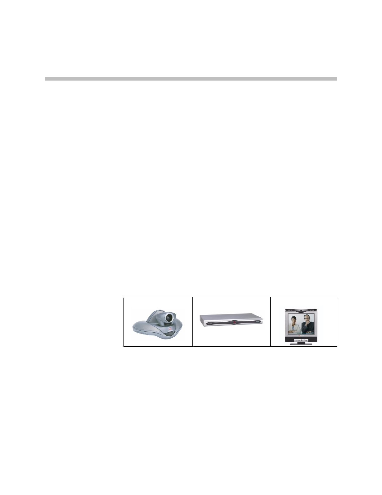
This guide covers instructions for the following models.
VSX set-top systems VSX component systems VSX desktop systems
1 - 1
Page 12
Administrator’s Guide for the VSX Series
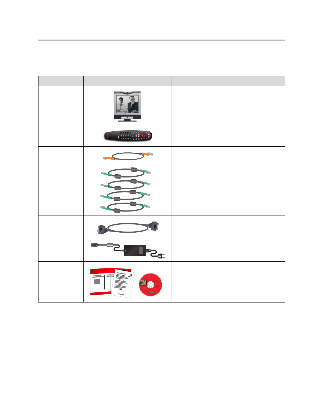
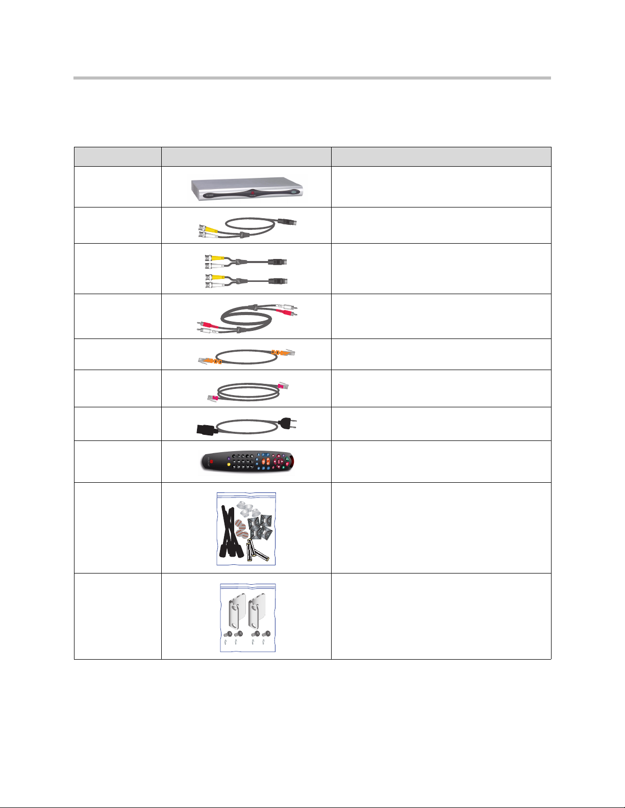
VSX 3000 and VSX 3000A Desktop Systems
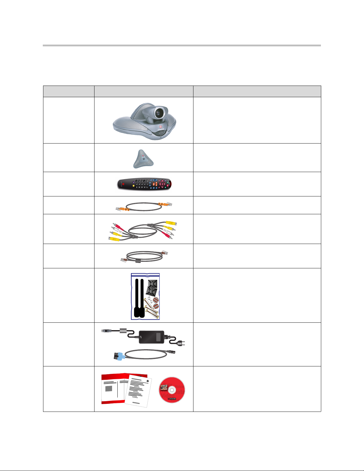
Two models of VSX 3000 and VSX 3000A are available — IP only, and IP with ISDN.
Name Component Description
VSX 3000
VSX 3000A
Remote Control The remote control is designed to make it easy to
LAN cable Connect the system to the IP network with the LAN
BRI cables
(ISDN model)
VGA cable Save space in your office by using the VGA cable
Power supply The power supply connects power to the system.
The VSX 3000 and VSX 3000A systems deliver
high-quality, video communication in an all-in-one
appliance that includes the camera, LCD screen,
speakers, and microphone.
set up and operate the system — color-coded
buttons correspond to system features.
cable.
Connect the system to the ISDN with the BRI
cables.
to connect your computer to the system’s 17”
high-resolution XGA display.
Documentation • Read Me First
• Setting Up the VSX 3000 System or Setting Up
the VSX 3000A System
• VSX documentation CD
1 - 2
Page 13
Introducing the VSX Series
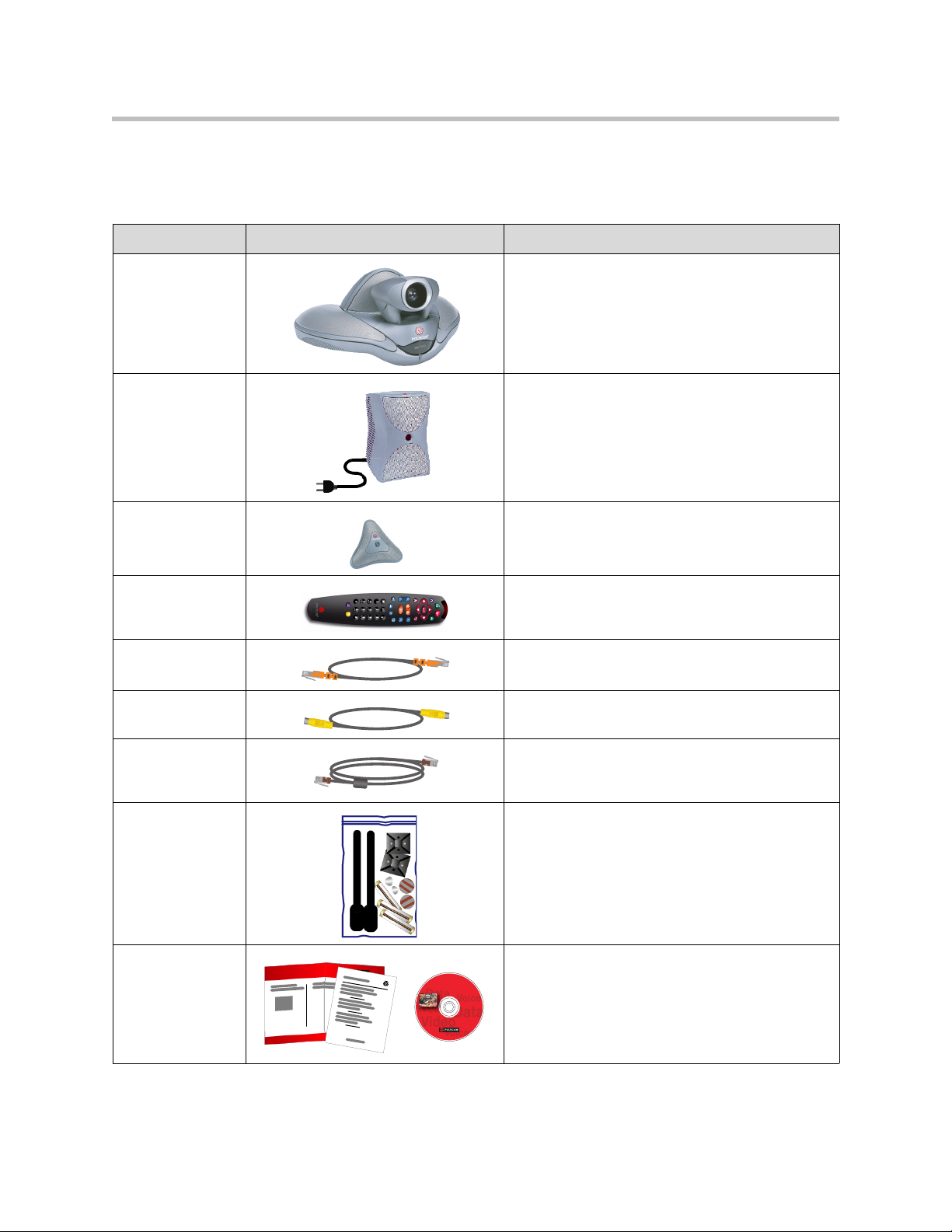
VSX 5000 Set-top System
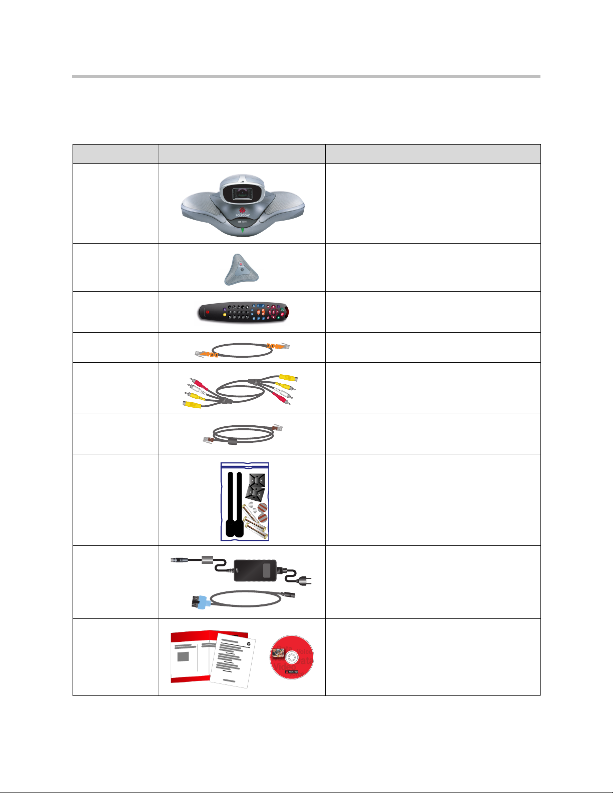
The VSX 5000 system includes the following components.
Name Component Description
VSX 5000 The VSX 5000 is a compact, entry-level system
with an all-electronic, built-in camera.
Microphone The microphone provides audio input to the
system.
Remote Control The remote control is designed to make it easy to
set up and operate the system — color-coded
buttons correspond to system features.
LAN cable Connect the system to the IP network with the LAN
cable.
Combination
audio/video cable
Conference link
cable
Hardware kit The hardware kit includes:
Power supply The power supply and power cable connects
Documentation • Read Me First
Connect a monitor with the combination
audio/video cable.
Connect the microphone or the optional Visual
Concert™ VSX data collaboration unit with the
conference link cable.
• Reusable cable ties
• Cable tie mounts
• Disks of hook-and-loop material
• Vinyl feet
• Batteries for the remote control
power to the system.
• Setting Up the VSX 5000 System
• VSX Documentation Library on CD
1 - 3
Page 14
Administrator’s Guide for the VSX Series
VSX 6000 and VSX 6000A Set-top Systems
The VSX 6000 and VSX 6000A systems include the following components.
Name Component Description
VSX 6000
VSX 6000A
Microphone The microphone provides audio input to the
Remote Control The remote control is designed to make it easy to
LAN cable Connect the system to the IP network with the LAN
Combination
audio/video cable
Conference link
cable
Hardware kit The hardware kit includes:
The VSX 6000 and VSX 6000A systems are
entry-level video conferencing systems for IP and
SIP networks only.
system.
set up and operate the system — color-coded
buttons correspond to system features.
cable.
Connect a monitor with the combination
audio/video cable.
Connect the microphone or the optional Visual
Concert VSX data collaboration unit with the
conference link cable.
• Reusable cable ties
• Cable tie mounts
• Disks of hook-and-loop material
• Vinyl feet
• Batteries for the remote control
Power supply The power supply and power cable connects
power to the system.
Documentation • Read Me First
• Setting Up the VSX 6000 System
• VSX Documentation Library on CD
1 - 4
Page 15
VSX 7000 and VSX 7000s Set-top Systems
The VSX 7000 and VSX 7000s systems include the following components.
Name Component Description
Introducing the VSX Series
VSX 7000
VSX 7000s
Subwoofer and
power
Microphone The microphone provides audio input to the
Remote Control The remote control is designed to make it easy to
LAN cable Connect the system to the IP network with the LAN
S-Video cable Connect a monitor with the S-video cable.
The VSX 7000 and VSX 7000s systems provide
cutting-edge video conferencing technology for IP
and other networks.
The subwoofer provides additional depth to the
sound, creating a high-quality sonic space
comparable to a home theater system.
system.
set up and operate the system — color-coded
buttons correspond to system features.
cable.
Conference link
cable
Hardware kit The hardware kit includes:
Documentation • Read Me First
Connect the microphone or the optional Visual
Concert VSX data collaboration unit with the
conference link cable.
• Reusable cable ties
• Cable tie mounts
• Disks of hook-and-loop material
• Vinyl feet
• Batteries for the remote control
• Setting Up the VSX 7000 System
• VSX Documentation Library on CD
1 - 5
Page 16
Administrator’s Guide for the VSX Series
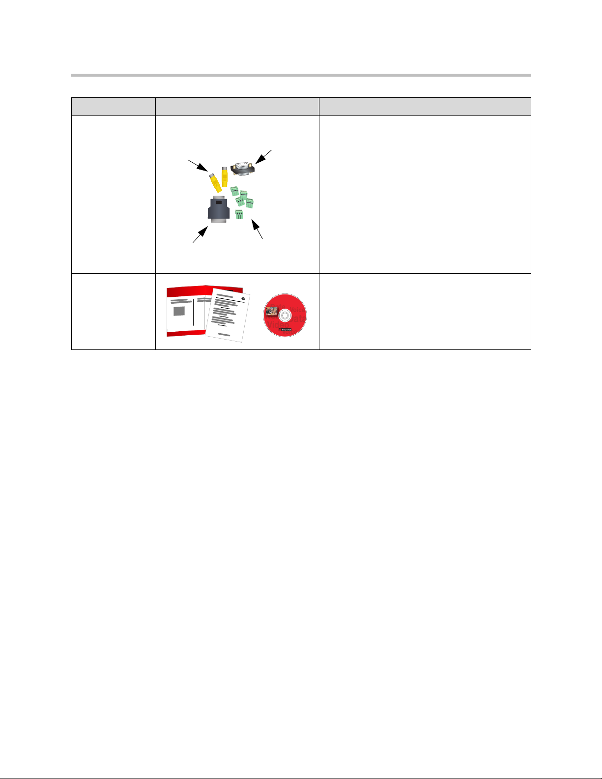
VSX 7000e Component System
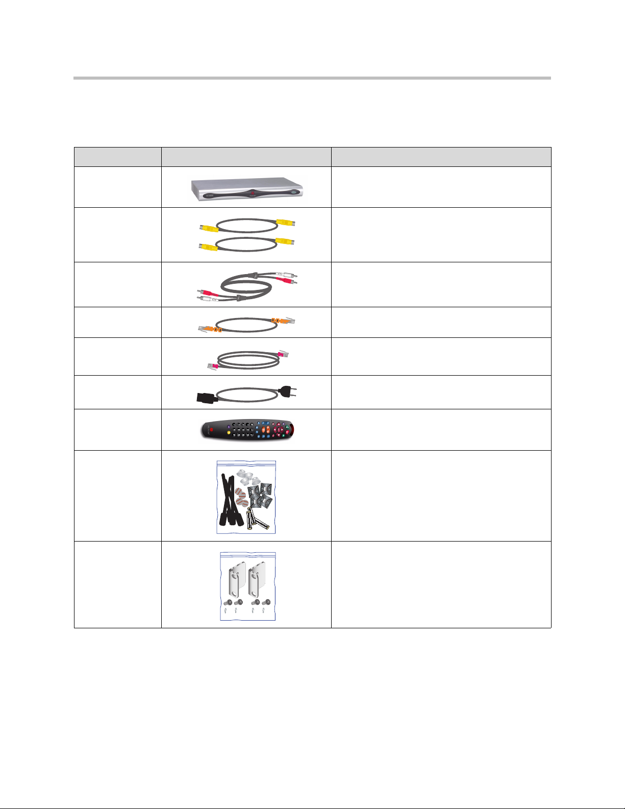
The VSX 7000e includes the following components.
Name Component Description
VSX 7000e The VSX 7000e is a video component system for
medium-sized conferencing rooms.
S-Video cables Connect monitors and third-party cameras with the
S-video cables.
Audio cable Connect the system’s audio output to the monitor
or to an external audio system.
LAN cable Connect the system to the IP network with the LAN
cable.
Telephone cable Connect the system to a telephone line.
Power cord Connect the system to a power source.
Remote Control The remote control is designed to make it easy to
set up and operate the system — color-coded
buttons correspond to system features.
Hardware kit The hardware kit includes:
• Reusable cable ties
• Cable tie mounts
• Disks of hook-and-loop material
• Vinyl feet
• Batteries for the remote control
Rack-mount
brackets and
screws
Attach the brackets to the system if you need to
mount it in a rack.
1 - 6
Page 17
Name Component Description
Introducing the VSX Series
Adapters Use the composite video adapters with VCR
Composite
video
adapters
Null-modem
adapters
cables.
Use the null-modem adapters with a serial cable
when connecting the VSX 7000e system to a
modem for closed captioning.
Use the DB-15 to DB-9 adapter to connect a
camera control cable to one of the VSX 7000e
system’s RS-232 ports.
DB-15 to
DB-9 adapter
Documentation • Read Me First
• Setting Up the VSX 7000e System
• VSX Documentation Library on CD
1 - 7
Page 18
Administrator’s Guide for the VSX Series
VSX 8000 Component System
The VSX 8000 system includes the following components.
Name Component Description
VSX 8000 The VSX 8000 system is a compact component
system for custom integration.
S-Video cable Connect a monitor with the S-video cable.
S-Video adapters Use with standard S-video cables to connect the
main camera and alternate main monitor to the
system’s BNC connectors.
Audio cable Connect the system’s audio output to the monitor
or to an external audio system.
LAN cable Connect the system to the IP network with the LAN
cable.
Telephone cable Connect the system to a telephone line.
Power cord Connect the system to a power source.
Remote Control The remote control is designed to make it easy to
set up and operate the system — color-coded
buttons correspond to system features.
Hardware kit The hardware kit includes:
• Reusable cable ties
• Cable tie mounts
• Disks of hook-and-loop material
• Vinyl feet
• Batteries for the remote control
Rack-mount
brackets and
screws
Attach the brackets to the system if you need to
mount it in a rack.
1 - 8
Page 19
Name Component Description
Introducing the VSX Series
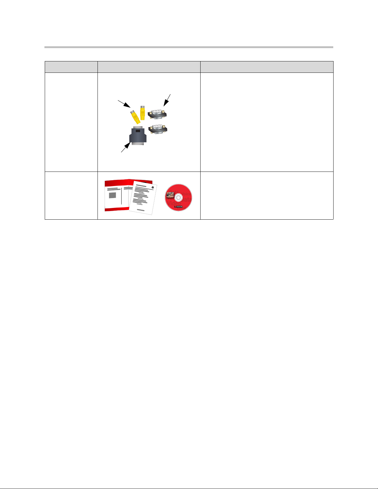
Adapters Use the composite video adapters with VCR
Documentation • Read Me First
Composite
video
adapters
DB-15 to
DB-9 adapter
Null-modem
adapter
Spring c age
connectors
cables.
The spring cage (Phoenix) connectors fit the
balanced audio inputs and outputs and infrared
sensor connectors on the system, and allow you to
re-terminate cables if necessary.
Use the null-modem adapter with a serial cable
when connecting the VSX 8000 system to a
modem for closed captioning.
Use the DB-15 to DB-9 adapter to connect a
camera control cable to one of the RS-232 ports, or
to connect a camera other than the PowerCam™ to
the main camera input.
• Setting Up the VSX 8000 System
• VSX Documentation Library on CD
Key Features
Breakthrough Video Quality
• Best for low bandwidth calls — The H.264 standard provides consistent,
high quality video at data rates up to 768kbps.
• Best for high bandwidth calls — Polycom’s own standards-based
Pro-Motion™ H.263 50/60 fields per second video provides television-like
quality for all VSX systems. In addition, the VSX 8000 supports
Pro-Motion H.264 for the highest quality video available at date rates from
256kbps to 2Mbps.
• Adjustable bandwidth for content — The call quality preference can be
set to Content (90% content, 10% people), People (10% content, 90%
people), or Both (50% content, 50% people).
1 - 9
Page 20

Administrator’s Guide for the VSX Series
Industry-Leading Audio Quality
• Polycom StereoSurround™ — StereoSurround is standard in VSX
systems. This feature enhances intelligibility by giving conference
participants a better spatial understanding of far site rooms.
• Integrated voice and video solution — Integrate the Polycom Vortex®
audio mixer with VSX set-top or component systems for custom-designed
integrated room audio systems that ensure the highest quality audio in all
VSX system video calls.
Rich Conference Experience
• Integrated video system and conference phone — Get the most out of
your conference room equipment by integrating your VSX video
conferencing system with the SoundStation VTX 1000® conference phone.
• High resolution content sharing — Conference participants can share
content easily from their computers with the Visual Concert™ VSX for
set-top systems, and the ImageShare™ II device for component systems.
People+Content™ IP, a software application, can also be used for sharing
content on any VSX system.
• Document camera and VCR/DVD as a content source — Specify a
document camera or VCR/DVD as a content source. In a dual monitor
configuration, the speaker will be on one monitor and the document
camera or VCR/DVD image will be on the second monitor.
• See more with single-monitor systems — Use Dual Monitor Emulation
(split-screen viewing) to see near-site people, far-site people, and content
on one monitor. Dual Monitor Emulation was designed for 16x9 displays,
but it can be used with standard 4x3 displays effectively.
• Single monitor VGA for VSX 5000, VSX 6000A, VSX 7000s, VSX 7000e,
or VSX 8000 — Connect a VGA monitor or projector as your primary
display device.
• Automatic camera tracking — Configure VSX systems with a Polycom
PowerCam™ Plus to track to the speaker’s voice or to camera presets.
• Multipoint capabilities — VSX 3000, VSX 3000A, VSX 7000, VSX 7000s,
and VSX 7000e systems with an internal MCU can host multipoint calls
that include up to four video sites, plus one audio site. The VSX 8000
provides multipoint support for calls that include up to six video sites,
plus one audio site.
1 - 10
Page 21

Enhanced User Experience
• Customizable home screen — Customize the home screen to support
different types of users:
— Novice users — Offer just a few options, so users need little or no
— Advanced users — Provide a wide range of video conferencing
• Customizable look and feel — Set up the workspace to suit your
environment.
— Screen colors and tones — Change the colors, ring tones, and error
— Camera names and icons — Name each video source and assign it an
— Support for ViewStation® users — Configure the workspace with
Introducing the VSX Series
training.
features.
tones to suit the décor and environment.
industry-specific icon so users can easily identify it during meetings.
the classic ViewStation look to build on users’ experience with
ViewStation video conferencing systems.
Easy Installation
• Call Scheduler — Use the calendar and call scheduling feature to schedule
video conferences. The system automatically calls the site you selected on
the date and time you specified. For recurring calls, you can indicate
whether you want the system to automatically make the call daily, weekly,
or monthly.
• Firewall (UPnP™) support — VSX systems offer support for routers that
support UPnP (Universal Plug and Play) NAT traversal, extending the
reach of video conferencing systems into homes and small businesses.
• Easy configuration wizard — The system setup wizard detects your
network connections and guides you through configuring the system to
work on an IP network or an ISDN.
1 - 11
Page 22

Administrator’s Guide for the VSX Series
Security
• Use AES encryption — Enable the AES encryption option to
• Connect encryption equipment to the system — Add the optional serial
• Use an optical dialing isolator — The serial V.35/RS-449/RS-530 network
• Control remote access — The local administrator can specify which
• Set the web access port — Enhance call security by specifying the web
• Enable Security Mode — Security Mode is based on Transport Layer
automatically encrypt calls to other AES-capable systems, without
external encryption equipment.
V.35/RS-449/RS-530 network interface module to the VSX 7000,
VSX 7000s, VSX 7000e, or VSX 8000 system.
interface module supports NSA-approved optical dialing isolators.
remote management interfaces can be used — FTP, Telnet, or the
VSX Web interface. The local administrator can configure a separate
password for remote management.
access port to be used by VSX systems.
Security (TLS) 1.0 using 168-bit Triple-DES. These protocols encrypt
management communication over IP, preventing access by unauthorized
users.
Remote Management
• Room monitoring — Administrators of VSX systems can monitor meeting
rooms in or out of a call using the Web Director feature in VSX Web.
• Language independence — Use VSX Web in your language to configure
and administer systems running in any other language.
• Secure remote management — The local administrator’s password on the
system prevents users from changing system configuration while
allowing you to manage the system remotely.
• Remote system configuration — Run the system setup wizard from your
web browser to get the system up and running remotely.
• Call Detail Reports — Access the system’s call history from VSX Web.
You can download the data to a spreadsheet application for sorting and
formatting.
• Remote diagnostics — Tools in VSX Web allow you to identify and
correct issues that affect the user’s experience.
• SNMP Reporting — VSX systems send SNMP reports to indicate
conditions.
1 - 12
Page 23
Setting Up Your System Hardware
This chapter provides information to supplement the setup sheets provided
with your system and its optional components. A printed copy of the system
setup sheet is provided with each VSX system. PDF versions of the system
setup sheets are available at www.polycom.com/videodocumentation.
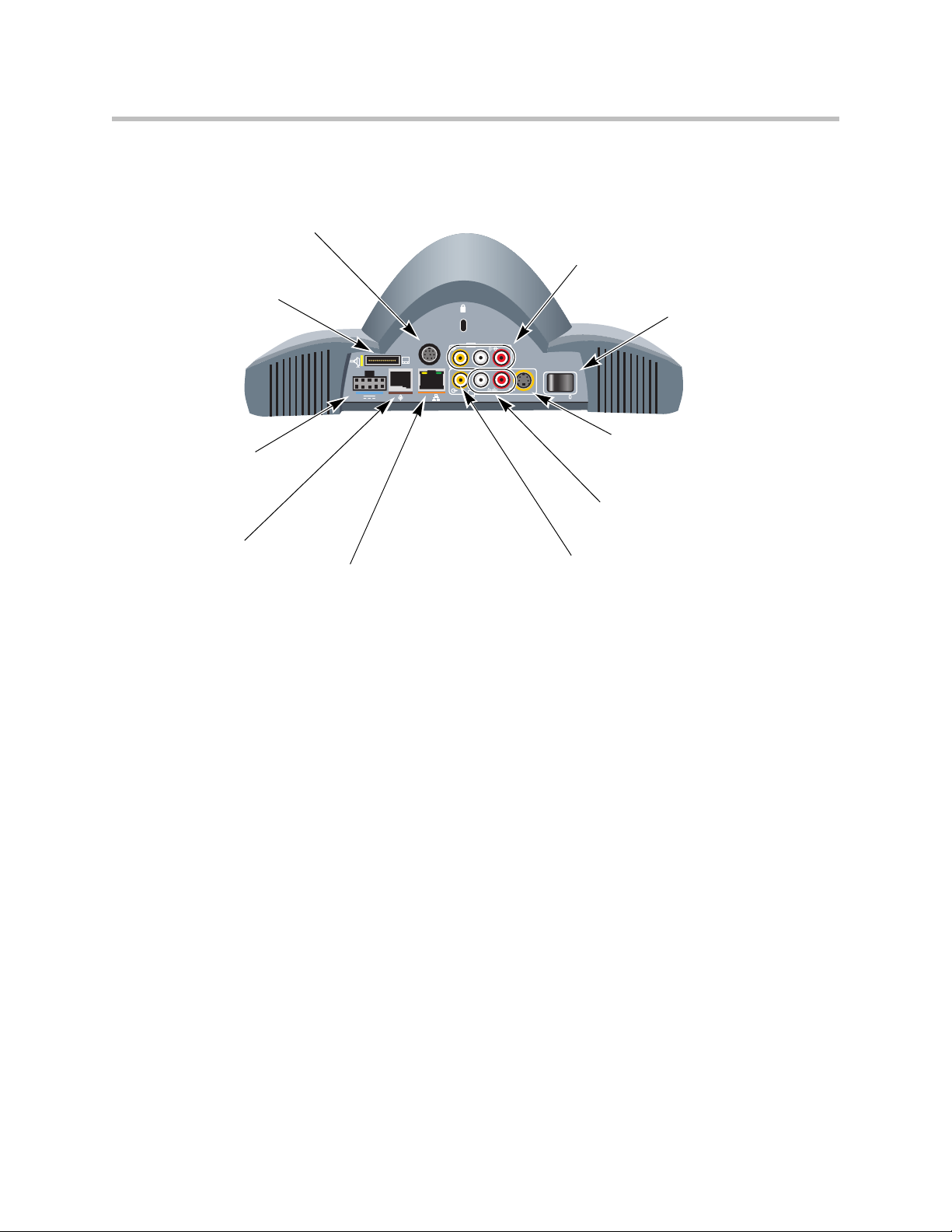
System Back Panel Views
These illustrations identify the systems’ back panel connectors.
2
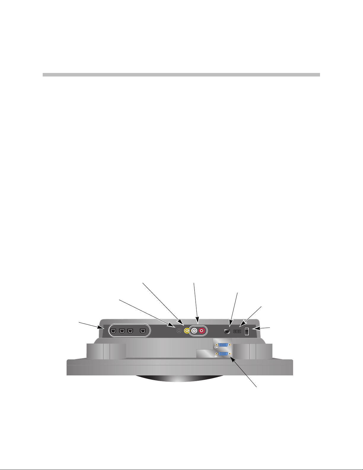
VSX 3000 and VSX 3000A Connector Panel
The connectors face downward on the VSX 3000 and VSX 3000A systems. This
is a view from underneath the system.
Composite video input to system
For video from camera or VCR/DVD
Stereo output from system
For desktop speakers
BRI ports
For ISDN calls
(Not present on
IP-only
systems)
Audio input to system
For audio from VCR/DVD
LAN port
For IP or SIP calls,
People+Content IP,
and VSX Web
Power connector
For power supply
Power switch
(one of three)
VGA input to system
For computer to use system as
a computer monitor
2 - 1
Page 24
Administrator’s Guide for the VSX Series
VSX 5000 Back Panel
Conference link
For Polycom microphone,
SoundStation VTX 1000, or
Visual Concert VSX
RS-232 serial port
For RS-232 device
VCR/DVD input to system
For VCR/DVD to play
content into calls
S-Video output from system
For second S-Video monitor
Power connector
For power supply
101010
24V 3A
LAN
LAN port
For IP or SIP calls,
People+Content IP,
and VSX Web
1
S-Video output
from system
For main monitor
2
VGA
Power switch
VGA output from system
For VGA monitor or projector
Audio output from system
For main monitor audio, or
for external speaker system
2 - 2
Page 25
VSX 6000 Back Panel
RS-232 serial port
For RS-232 device
Additional display connector
For additional display adapter to
connect a monitor or projector
Setting Up Your System Hardware
VCR/DVD input to system
For VCR/DVD to play
content into calls
Power switch
Power connector
For power supply
Conference link
For Polycom microphone,
SoundStation VTX 1000, or
Visual Concert VSX
VGA
3
0101
2
LAN
LAN port
For IP or SIP calls,
People+Content IP,
and VSX Web
1
S-Video output from system
For main monitor
Audio output from system
For VCR/DVD to record call
audio, or for external speaker
system
Composite video output
from system
For VCR/DVD to record
call video, or for
composite TV monitor
2 - 3
Page 26
Administrator’s Guide for the VSX Series
VSX 6000A Back Panel
RS-232 serial port
For RS-232 device
Power connector
For power supply
Conference link
For Polycom microphone,
SoundStation VTX 1000, or
Visual Concert VSX
101010
24V 3A
LAN
LAN port
For IP or SIP calls,
People+Content IP,
and VSX Web
VCR/DVD input to system
For VCR/DVD to play
content into calls
1
from system
For main monitor
S-Video output from system
For second S-Video monitor
Not enabled if monitor 1 is
VGA
2
VGA
Power switch
VGA output from system
For VGA monitor or projector
Audio output from system
For external speaker systemS-Video output
2 - 4
Page 27
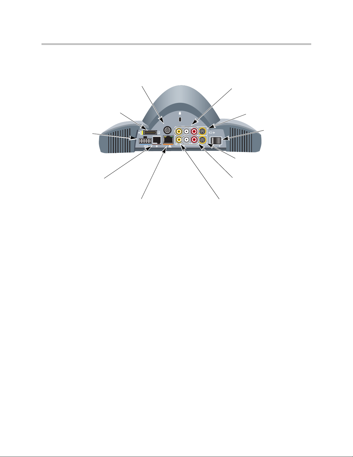
VSX 7000 Back Panel
RS-232 serial port
For touch panel, second camera
control, or other RS-232 device
Additional display connector
For additional display adapter to
connect a monitor or projector
Setting Up Your System Hardware
VCR/DVD input to system
For VCR/DVD to play content
into calls
S-Video input to system
For additional camera
Power connector
For subwoofer
(houses power
supply and optional
network interface
module)
Conference link
For Polycom microphone,
SoundStation VTX 1000, or
Visual Concert VSX
VGA
3
2
LAN port
For IP or SIP calls,
People+Content IP,
and VSX Web
0101
2
LAN
1
Power switch
S-Video output from system
For main monitor
Audio output from system
For VCR/DVD to record call
audio, or for external speaker
system
Composite video output from system
For VCR/DVD to record call video, or for
composite monitor
2 - 5
Page 28
Administrator’s Guide for the VSX Series
VSX 7000s Back Panel
Conference link
For Polycom microphone,
SoundStation VTX 1000, or
Visual Concert VSX
RS-232 serial port
For touch panel, second
camera control, or other
RS-232 device
Power connector
For subwoofer
(houses power
supply and optional
network interface
module)
LAN port
For IP or SIP calls,
People+Content IP,
and VSX Web
24V 3A
VCR/DVD input to system
For VCR/DVD to play content
into calls
101010
LAN
VCR/DVD output from system
For VCR/DVD to record calls
S-Video input to system
For additional camera
Audio output from system
For external speaker system
VGA output from system
For VGA monitor
or projector
2
2
1
VGA
Power switch
S-Video output from system
For second S-Video monitor
S-Video output from system
For main monitor
2 - 6
Page 29
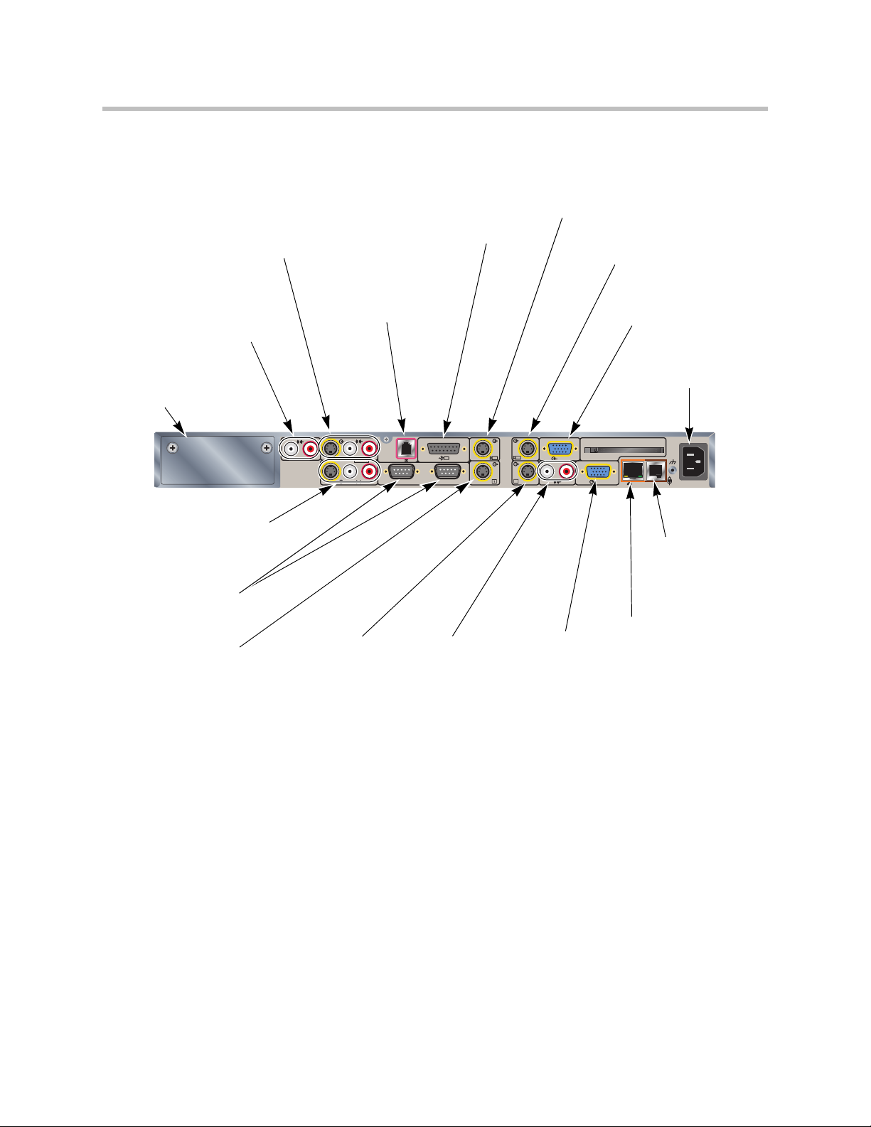
VSX 7000e Back Panel
Setting Up Your System Hardware
Line level audio
input to system
For ImageShare II,
computer, or other
audio source
Network interface
bay
For network
interface module
VCR/DVD output
from system
For VCR/DVD to
record
RS-232 serial ports
For touch panel,
camera control, or
other RS-232 device
S-Video output
from system
For main monitor
VCR/DVD input to
system
For VCR/DVD to
play content into
calls
S-Video output
from system
For additional
S-Video monitor
Analog phone
port
For analog
phone line
3
VCR/DVD
IOIOIO
Audio output
from system
For external
speaker system
Camera 1 control
connector
For camera 1 PTZ
control
2
1
1
2
VGA output
from system
For VGA monitor
or projector
S-Video input to system
For main camera
S-Video input to
system
For additional
camera
VGA input to system
For ImageShare II or
computer VGA output
Power connector
For power cord
90-250VAC 50/60Hz 4A
PC CARD
VGA
2
VGA 2
LAN
Conference link
For Polycom
microphone or
SoundStation
VTX 1000
LAN port
For IP or SIP calls,
People+Content IP,
and VSX Web
2 - 7
Page 30
Administrator’s Guide for the VSX Series
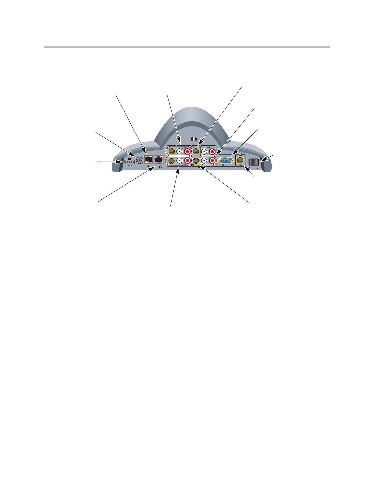
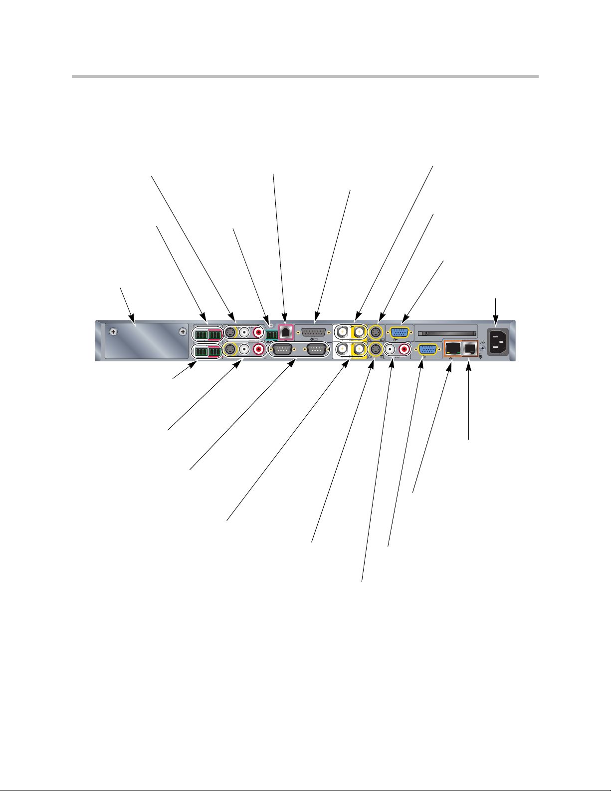
VSX 8000 Back Panel
VCR/DVD input
to system
For VCR/DVD to
play content into
calls
Balanced audio
input to system
For mixer or powered
microphones
Network interface
bay
For network interface
module
Balanced audio
output from system
For external audio
equipment
VCR/DVD output
from system
For VCR/DVD to
record
RS-232 serial ports
For touch panel,
camera control, or
other RS-232 device
Monitor 1 Y and C
output from system
For main monitor
IR sensor
input to
system
For external
IR sensor
3
VCR/DVD
Analog phone
port
For analog
phone line
IR
IOIOIO
1
S-Video output
from system
For additional
S-Video monitor
Camera 1 control
connector
For main camera
PTZ control
1
2
1
Camera 1 Y and C
input to system
For main camera
S-Video input to system
For a second camera
VGA input to system
For ImageShare II or
computer VGA output
Power connector
For power cord
90-250VAC 50/60Hz 4A
2
PC CARD
VGA
2
VGA
LAN
Conference link
For Polycom microphone
or
SoundStation VTX 1000
LAN port
For IP or SIP calls,
People+Content IP,
and VSX Web
VGA output from system
For VGA monitor or projector
2 - 8
Audio output from system
For external speaker system
Page 31

Positioning the System
Position the system so that the camera does not face toward a window or other
source of bright light.
Place the camera and display together so that people at your site face the
camera when they face the far site display.
Positioning Desktop Systems
The VSX 3000 and VSX 3000A systems are personal video conferencing
systems for the desktop. These systems include a video conferencing codec,
17-inch monitor, two microphones, and two speakers.
Setting Up Your System Hardware
To position the system:
¾ Place the VSX 3000 or VSX 3000A system on your desktop or on a table in
a small conference room, leaving enough space so that you can connect the
cables easily.
2 - 9
Page 32

Administrator’s Guide for the VSX Series
If you need to place the system face-down to connect the cables, make sure that
the camera does not touch the work surface. The weight of the system can damage
the camera mount.
Positioning Set-top Systems
The VSX 5000, VSX 6000, VSX 6000A, VSX 7000, and VSX 7000s systems are
designed to be placed on top of a monitor. You can order a shelf that can be
mounted on a wall or placed on top of a flat-panel monitor.
If you received a network interface module with your system, you may find it
convenient to install it before positioning the system. Refer to the installation
sheet that you received with the network interface module.
To position the system:
1. The hardware kit you received with the system includes a pair of
self-adhesive feet. If the monitor’s chassis slopes back sharply, install the
feet on the bottom of the system to stabilize it.
Feet
2. Place the system in the desired location, with the rounded front portion
hanging over the front of the monitor or shelf. Leave enough space to
work, so that you can connect the cables easily.
3. Remove the packaging collar from around the VSX system camera.
2 - 10
Page 33

Positioning Component Systems
The VSX 7000e and VSX 8000 systems are designed to be placed on a tabletop
or in an equipment rack.
If you received a network interface module with your system, you may find it
convenient to install it before positioning the system. Refer to the installation
sheet that you received with the network interface module.
To position the system:
1. Install the mounting brackets on the system if you need to mount it in an
equipment rack, or install the self-adhesive feet if you will place the
system on a table or shelf.
2. Place the system in the desired location. Leave enough space to work, so
that you can connect the cables easily.
Setting Up Your System Hardware
3. Place the camera on or near the monitor displaying the far site so that
people look towards the camera during calls.
Connecting to the LAN
All VSX systems can be connected to a LAN to make IP calls.
You must connect the system to a LAN to:
• Make IP or SIP calls
• Use the Global Directory Server
• Use VSX Web or People+Content IP
• Update system software using the Polycom Softupdate program
The back panel view for your system shows the location of the LAN connector.
Refer to the previous section, System Back Panel Views. The setup sheet for
your system also provides this information.
2 - 11
Page 34

Administrator’s Guide for the VSX Series
Connecting to Other Networks
The following network interface modules are available with some VSX
systems:
•BRI — Allows you to connect to an ISDN network using up to four BRI
lines.
•PRI — Allows you to connect to an ISDN network using a PRI line.
• V.35/RS-449/RS-530 — Allows you to connect to third-party network
equipment, including encryption equipment and RS-366 dialers.
The table below shows the network interfaces available for each model.
ISDN - BRI ISDN - PRI V.35/RS-449/RS-530
VSX 3000
VSX 3000A
VSX 5000 Available in a separate
VSX 6000
VSX 6000A
VSX 7000 Available Available Available
VSX 7000s Available Available Available
VSX 7000e Available Available Available
VSX 8000 Available Available Available
Built in to model with IP
and ISDN
housing
Not Available Not Available Not Available
Network interface modules fit into subwoofer housing
Network interface modules fit into subwoofer housing
Network interface modules fit into back panel
Network interface modules fit into back panel
Not Available Not Available
Not Available Not Available
When you purchase a network interface module, you receive a setup sheet that
shows how to install it in your system.
2 - 12
Page 35

Connecting Desktop Systems to the ISDN BRI Network
The VSX 3000 and VSX 3000A desktop systems are available with or without
the built-in Quad BRI network interface. The setup sheet for the IP with ISDN
system shows how to connect it to a BRI network.
If you purchased the VSX 3000 or VSX 3000A system with IP and ISDN, you
will need:
•NT-1 device, if the system will be connected to a network that provides a
U interface
• Up to 4 BRI lines that will not be shared with other equipment
If you connect fewer than four BRI ports on the system’s network interface
module, connect them in ascending order, starting with port 1.
The diagram below shows a general view of how to connect the VSX 3000 or
VSX 3000A system to the ISDN using the Quad BRI network interface.
Setting Up Your System Hardware
VSX 3000 or
VSX 3000A with
IP and ISDN
NT-1 device
(if not connecting
to a PBX)
ISDN
2 - 13
Page 36
Administrator’s Guide for the VSX Series
Connecting Set-top and Component Systems to ISDN or Other Networks
If you received a network interface module with your system, you may find it
convenient to install it before positioning the system. Refer to the setup sheet
that you received with the network interface module.
You will need the following network hardware:
If your network is... You will need
BRI • NT-1 device, if the system will be connected to a
network that provides a U interface. Do not use an
NT-1 device if your PBX network provides an S/T
interface.
• Up to 4 BRI lines that will not be shared with other
equipment.
If you connect fewer than four BRI ports on the
system’s network interface module, connect them in
ascending order, starting with port 1.
The diagram below shows a general view of how network interface modules
are connected in set-top and component VSX systems.
VSX system
PRI
(North America and
Japan)
PRI
(outside North America
and Japan)
Serial
V.35/RS-449/ RS-530
Network
interface
module
• PBX crossover cable, if required for your PBX.
• Channel Service Unit (CSU) — not required if you
connect the system to a PBX network.
• PRI line.
• 75 W coaxial adapter, if the network connection is
via a 75 W coaxial cable.
• PBX crossover cable, if required for your PBX.
• PRI line.
• Third-party network equipment and cables.
Contact your network equipment vendor to obtain the
appropriate cables for the equipment you connect to
this interface. If you use only one cable, connect it to
port 1 of the network interface module and to the
lowest-numbered port of the data communications
equipment.
Additional device
Examples:
Quad BRI — NT-1
PRI — CSU
V.35/RS-449/RS-530 —
encryption equipment
Network
2 - 14
Page 37

Connecting Cameras
All VSX systems allow you to connect a second camera or other video source.
The component systems require that you connect at least one camera so that
your site can send video.
Connecting Document Cameras to Desktop Systems
You can connect a document camera to show detailed close-up views of
printed documents or other small items. The VSX 3000 and VSX 3000A
systems provide one composite video input.
Refer to the system setup sheet for information about connecting a document
camera.
Connecting Cameras to Set-top Systems
VSX 7000 and VSX 7000s systems provide an S-Video input for a second
camera. You can connect a camera to the VCR video input on the VSX 5000,
VSX 6000, or VSX 6000A system. On the VSX 6000 and VSX 6000A systems,
the video input is for a composite video signal. Refer to the release notes for a
list of supported PTZ cameras.
Setting Up Your System Hardware
VSX 5000, VSX 6000, and VSX 6000A systems do not provide pan/tilt/zoom
(PTZ) control for a second camera.
You can use the RS-232 serial port on the VSX 7000 or VSX 7000s system for
camera control. Refer to your system’s setup sheet for connection details.
Connecting Cameras to Component Systems
If you have a component system, you need to connect a camera to the system
so that people at other sites can see your site. Refer to your system’s setup
sheet for connection details.
The component systems provide S-video connections for two cameras. The
VSX 8000 system provides the S-video signal to the main camera through BNC
connectors. Refer to the release notes for a list of supported PTZ cameras.
You can configure a VSX 7000e or VSX 8000 system with a Polycom
PowerCam Plus to track to the speaker’s voice or to camera presets.
2 - 15
Page 38

Administrator’s Guide for the VSX Series
Points to note about automatic camera tracking with the PowerCam Plus
camera:
• Automatic camera tracking works best at distances of 15 feet (4.6 m) or less.
• Automatic camera tracking works best if you face the camera when you speak.
• Leave at least one foot (0.3 m) of space above, behind, to the right, and to the
left of the camera. Echoes from nearby surfaces interfere with tracking.
• Automatic camera tracking works best in rooms with good acoustics.
• For information about user interface settings required for automatic camera
tracking, refer to Configuring Automatic Camera Tracking on page 4-4.
Using a Desktop System as the Monitor for a Computer
You can use the VSX 3000 or VSX 3000A system as a high-resolution XGA
display for your computer, as shown on the system setup sheet.
To use the VSX 3000 or VSX 3000A system as the monitor for a computer:
1. Connect the VGA cable from the VGA connector on the back of the
VSX 3000 or VSX 3000A system to the VGA connector on your computer.
2. To use the system’s built-in speakers for your computer’s audio, connect
an audio cable from your computer to the audio input connector on the
left side of the VSX 3000 or VSX 3000A system.
2 - 16
Page 39

Connecting Monitors and Projectors
If you have a set-top or component system, you need to connect a monitor to
the system to see the people at the far site. Refer to your system’s setup sheet
for connection details. The following table shows the different ways you can
connect monitors to a VSX system. The main monitor is the monitor that
displays the VSX system user interface.
VSX System Main Monitor Second Monitor
Setting Up Your System Hardware
VSX 5000, VSX 6000, VSX 6000A,
VSX 7000, VSX 7000s, VSX 7000e,
VSX 8000
VSX 5000, VSX 6000, VSX 6000A,
VSX 7000, VSX 7000s, VSX 7000e,
VSX 8000
VSX 5000, VSX 6000, VSX 6000A,
VSX 7000, VSX 7000s, VSX 7000e,
VSX 8000
VSX 5000, VSX 6000A, VSX 7000s,
VSX 7000e, VSX 8000
Make sure the settings on your monitor are appropriate for video conferencing
applications. For more information about configuring your monitor’s settings,
refer to Adjusting the Monitor’s Color Balance, Sharpness, and Brightness on
page 4-12.
Connecting Monitors to Set-Top Systems
If you have a VSX 5000, VSX 6000A, or VSX 7000s system, you can use a VGA
monitor instead of a TV monitor.
TV (NTSC or PAL) None
TV (NTSC or PAL) TV (NTSC or PAL)
TV (NTSC or PAL) VGA monitor
VGA monitor Not available
You can add the optional components described in the following sections.
Additional TV Monitor
The set-top systems provide a second S-Video output for a TV monitor. If you
have a VSX 6000 or VSX 7000 system, you need an additional display adapter
to connect a second monitor.
Because of their screen resolution, TV monitors are best for showing people
and for playing recorded material from VCR or DVD players.
2 - 17
Page 40

Administrator’s Guide for the VSX Series
VGA Monitor or Projector
The set-top systems provide a VGA output for a computer monitor or
projector. If you have a VSX 6000 or VSX 7000 system, you need an additional
display adapter to connect a VGA monitor or projector.
Because of their screen resolution, VGA monitors and projectors are best for
showing content from computers.
Connecting Monitors to Component Systems
You can connect either a TV monitor or a VGA monitor to your VSX system.
The component systems provide S-video connections for the main TV monitor.
On the VSX 8000 system, the main monitor uses BNC connectors.
You can add the optional components described in the following sections.
Additional TV Monitor
The component systems provide a second S-Video output for a TV monitor.
This uses a standard mini-DIN connector.
VGA Monitor or Projector
The component systems provide a VGA output for a computer monitor or
projector.
2 - 18
Page 41

Setting Up Your System Hardware
Connecting Microphones or a SoundStation VTX 1000
If you have a set-top system or a component system, you must connect at least
one microphone or a SoundStation VTX 1000 conference phone so that your
site can send audio.
About Polycom Microphones and the SoundStation VTX 1000
Polycom microphones each contain three microphone elements for 360°
coverage.
The SoundStation VTX 1000 conference phone uses a similar design, and
behaves the same way as a Polycom microphone.
Microphone elements in the
Polycom microphone
Microphone coverage shown from above
Monaural operation
Microphone elements in the
SoundStation VTX 1000
conference phone
Using StereoSurround
2 - 19
Page 42

Administrator’s Guide for the VSX Series
The microphone and the SoundStation VTX 1000 both pick up sound from the
sides.
For best audio, place the microphone or SoundStation VTX 1000:
• On a hard, flat surface (table, wall, or ceiling) away from obstructions, so
the sound will be directed into the microphone elements properly.
• Near the people closest to the monitor.
• In large conference rooms, you may need more than one microphone. If
you are using a SoundStation VTX 1000, you may need to connect its
extension microphones.
Connecting Polycom Microphones to Set-Top or Component Systems
To pick up audio from your site, you must connect a microphone or a
SoundStation VTX 1000 conference phone to the system. Refer to your
system’s setup sheet for connection details.
You can use a Polycom microphone or a SoundStation VTX 1000 with the system,
but the two may not be used together.
You may place the microphones on the table, or you may mount them to the
ceiling. A ceiling mount kit is available for Polycom microphones.
You can connect two additional Polycom microphones to a VSX 7000,
VSX 7000s, or component VSX system.
2 - 20
Page 43

The following diagram shows microphone connection options for VSX set-top
systems.
Any set-top or component system
VSX 7000 or any component system
VSX 7000 or any component system
Setting Up Your System Hardware
.
50 ft (15 m)
2457-20910-050
or 30 ft (9 m)
2457-20910-001
The ferrite bead
must be at the
end connected
to the system.
30 ft (9 m)
2457-20910-003
or 10 ft (3 m)
2457-20910-002
30 ft (9 m)
2457-20910-003
or 10 ft (3 m)
2457-20910-002
2 - 21
Page 44

Administrator’s Guide for the VSX Series
Placing Polycom Microphones to Send Stereo from Your Site
The VSX 7000, VSX 7000s, and component VSX systems allow you to send
stereo using any valid number of Polycom microphones.
If you use a single microphone to send stereo, one microphone element picks
up audio from the left side of the room, one picks up the right side of the room,
and the third is not used.
Stereo using one
microphone Stereo using two microphones Stereo using three microphones
not used
left right
left
left
right right
left
not used
left right
not used
left right
right
left
left
left right
left
not used
not used
left
not used
left
not used
left
right
right right
right
right
right
2 - 22
Page 45

Setting Up Your System Hardware
The following illustrations show microphone placement for different room
layouts.
One Microphone
Round Table
Square Table
Long Table
Wide Table
Place microphones so that:
Two Microphones
Three Microphones
• The logo on each microphone points toward the monitor.
• The microphone closest to the monitor is parallel with, or in front of, the
person nearest the monitor.
After you power on the system, you will need to configure the system to send
stereo as described in Configuring StereoSurround Settings on page 4-25.
2 - 23
Page 46

Administrator’s Guide for the VSX Series
Connecting a SoundStation VTX 1000 to a Set-top or Component System
You can connect a SoundStation VTX 1000 conference phone in place of a
Polycom microphone. In large rooms, you may also need to use the extension
microphones provided with the SoundStation VTX 1000. Refer to your
system’s setup sheet and the setup sheet provided with the
SoundStation VTX 1000 for connection details.
You can use a Polycom microphone or a SoundStation VTX 1000 with the
system, but the two may not be used together. The following table shows valid
and non-valid equipment configurations using the SoundStation VTX 1000
conference phone.
This is valid: This is not valid:
2 - 24
To take advantage of the latest integration features, the VSX system requires
version 8.0 or later software and the SoundStation VTX 1000 requires version
1.5 or later software.
Page 47

Setting Up Your System Hardware
Placing a SoundStation VTX 1000 Phone to Send Stereo from Your Site
The VSX set-top and component systems allow you to send stereo using a
SoundStation VTX 1000 conference phone, with or without extension
microphones.
The SoundStation VTX 1000 contains three microphone elements, just as
Polycom microphones do. When StereoSurround is enabled, one microphone
element picks up audio from the left side of the room, one picks up the right
side of the room, and the third is disabled, as shown in the following diagram.
Stereo using a
SoundStation VTX 1000
not used
left
right
Stereo using a
SoundStation VTX 1000 with
microphones
not used
left
left
right
right
The following illustrations show how to place the SoundStation VTX 1000
conference phone for different room layouts.
SoundStation
VTX 1000
Round Table
Square Table
SoundStation
VTX 1000 with
microphones
Long Table
Wide Table
Position the SoundStation VTX 1000 so that:
• The keypad should be pointing away from the monitor.
• The SoundStation VTX 1000 should be parallel with, or in front of, the
person nearest the monitor.
2 - 25
Page 48

Administrator’s Guide for the VSX Series
Connecting Powered Microphones or a Mixer to a VSX 8000 Component System
You can connect two powered microphones directly to the VSX 8000 system,
or you can connect several studio-type microphones to the VSX 8000 system
through an audio mixer.
The VSX 8000 is designed to work with Polycom Vortex mixers. For top
performance, you need Vortex firmware 2.5.2 or later, Conference
Composer™ version 2.7.0 or later, and VSX system software version 8.5 or
later. Refer to your system’s setup sheet for connection details.
Connecting Speakers
You can connect speakers to any VSX system. Some VSX systems have built-in
speakers.
Connecting Speakers or Headphones to Desktop Systems
You can connect desktop speakers to provide better audio for the VSX 3000 or
VSX 3000A system if you place it in a large room, or you can connect
headphones to listen to calls privately. The system’s speaker connector is on
the system’s right side panel, and the headphone connector is on the front of
the system.
Refer to your system’s setup sheet for connection details.
Connecting Speakers to Set-top Systems
If you have a VSX 5000, you must connect speakers to play audio from the far
site. You can use the speakers built into the main monitor.
The other set-top systems have built-in speakers. You can connect an external
speaker system such as the Polycom StereoSurround kit to provide more
volume and richer sound in large rooms. Refer to your system’s setup sheet for
connection details.
Connecting Speakers to Component Systems
You must connect at least one speaker to play audio from the far site. You can
use the speakers built into the main monitor, or you can connect an external
speaker system such as the Polycom StereoSurround kit to provide more
volume and richer sound in large rooms. Refer to your system’s setup sheet for
connection details.
2 - 26
Page 49
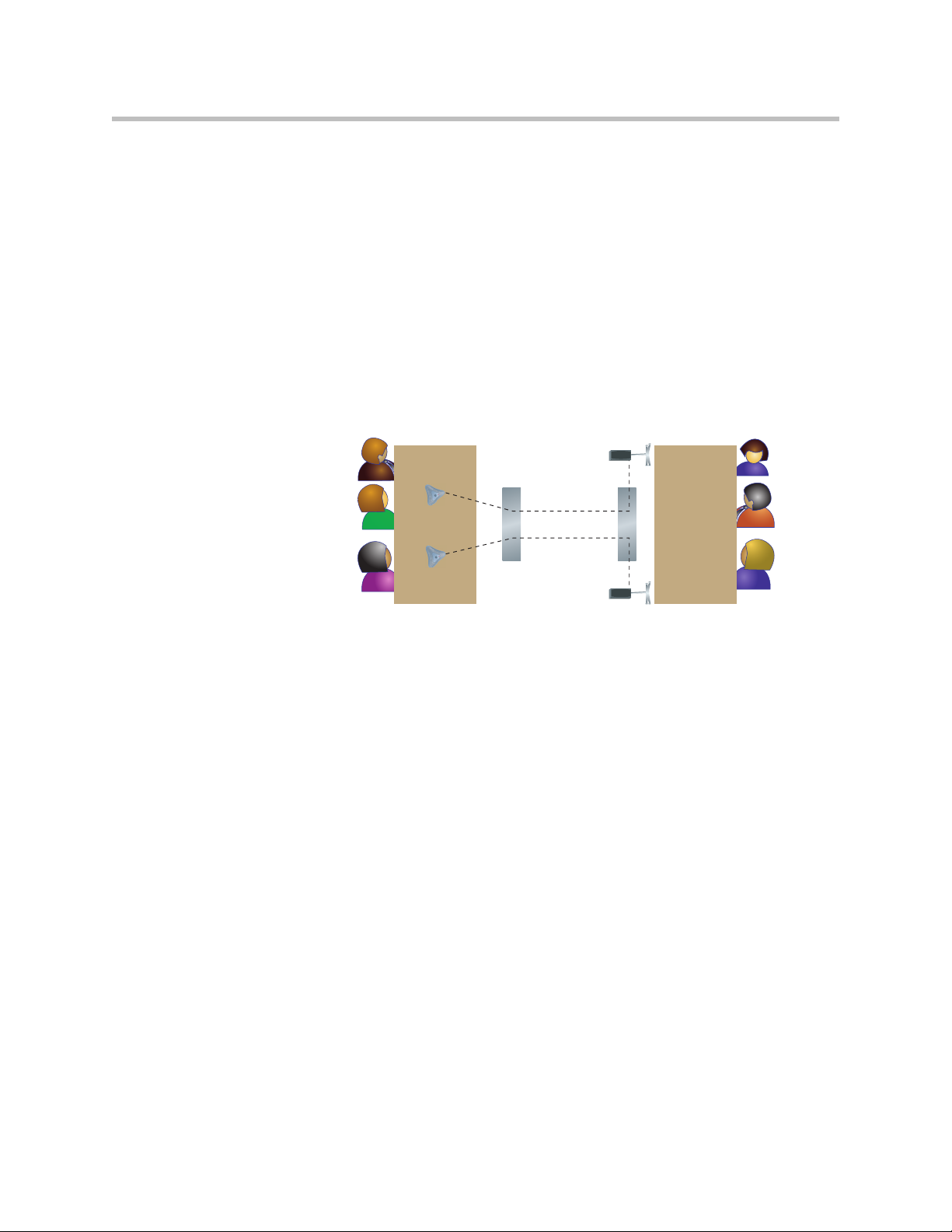
Placing Speakers to Play Stereo from Far Sites
The Polycom StereoSurround kit is designed for use with VSX systems. It
includes two speakers and a subwoofer. If you do not choose to connect
external speakers, you can use your monitor’s speakers to receive stereo.
You cannot receive stereo with a set-top VSX system using the system’s
built-in speaker.
When you set up the system for StereoSurround, the left microphone and
speaker should be on the left from the local room perspective. The system
reverses the left and right channels for the far site, as shown in the following
illustration. This ensures that the sound comes from the appropriate side of the
room.
Setting Up Your System Hardware
Left
Right Left
Sending stereo
Right
Receiving stereo
2 - 27
Page 50

Administrator’s Guide for the VSX Series
Place the speaker connected to the audio system’s right channel on the right
side of the system, and the other speaker on the left side. For best results, place
the speakers about 60° apart as seen from the center of the conference table.
Left speaker
Connect to left
audio output
(white)
60˚
If you are using a subwoofer, place it beside a wall or in a corner near the
speakers.
Connecting Content Sharing Equipment
All VSX systems can play VCR tapes or DVDs into calls. All set-top and
component VSX systems also provide ways to show material from your
computer.
Right speaker
Connect to right
audio output
(red)
Connecting VCR/DVDs
You can connect a VCR/DVD to any VSX system to play VCR tapes or DVDs
into calls. If your system is a VSX 6000, VSX 7000, VSX 7000s, or component
system, you can also connect a VCR/DVD to record your video conferences.
To set up a VCR or DVD to play:
¾ On the VCR/DVD, connect the outputs to the VCR/DVD inputs on the
The microphone inputs remain active while the VCR/DVD is playing. Call
participants may wish to mute the microphones while playing VCR/DVD
content.
2 - 28
VSX system. The system’s VCR/DVD inputs are on the top row of
connectors. Refer to your system’s setup sheet for connection details.
Page 51
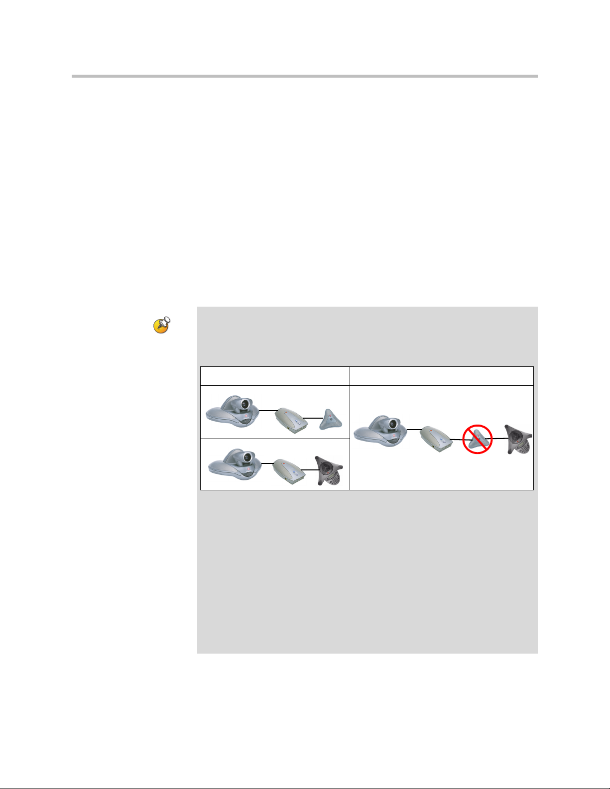
To connect a VCR or DVD to record:
¾ On the VCR/DVD, connect the inputs to the VCR/DVD outputs on the
VSX system. The system’s VCR/DVD outputs are on the bottom row of
connectors. Refer to your system’s setup sheet for connection details.
For information about configuring the VSX system to record video
conferences, refer to Recording a Call to Videotape or DVD on page 4-18.
Connecting a Visual Concert VSX to Set-top Systems
To show material from your computer, you may connect a Visual Concert VSX
unit to any set-top system in the VSX series. Refer to Setting up the Visual
Concert VSX for connection details.
The Quick Tips for Visual Concert VSX provides information for people using
the device in meetings.
Points to note about Visual Concert VSX:
• You can use Visual Concert VSX with a Polycom microphone or a
SoundStation VTX 1000 conference phone, but not with both.
Setting Up Your System Hardware
This is valid: This is not valid:
• You can use Visual Concert VSX with two Polycom microphones if you have a
VSX 7000 or VSX 7000s system.
• When you use Visual Concert VSX with a microphone or with two microphones,
the order in which you connect them does not matter.
• The Visual Concert VSX and the VSX system require separate LAN
connections. The Visual Concert VSX provides LAN connections for three
computers, including the one sharing content.
• You can connect a VGA monitor or projector directly to the Visual Concert VSX.
This lets the people at your site see content from your computer at its original
resolution. The resolution may be reduced if you display it on a VGA monitor
connected to the VSX system.
• You will need to set the computer’s screen resolution to match the VGA output
of the Visual Concert VSX.
2 - 29
Page 52
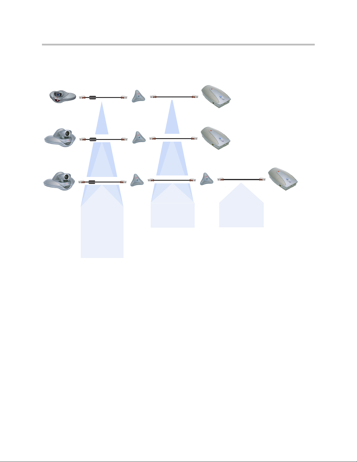
Administrator’s Guide for the VSX Series
The following diagram shows supported cable configurations for connecting
a Visual Concert VSX with one microphone or two microphones.
VSX 5000
VSX 6000
VSX 6000A
VSX 7000
VSX 7000s
.
The Visual Concert VSX
and microphones may be
connected in any order.
50 ft (15 m)
2457-20910-050
or 30 ft (9 m)
2457-20910-001
The ferrite bead
must be at the
end connected
to the system.
30 ft (9 m)
2457-20910-003
or 10 ft (3 m)
2457-20910-002
30 ft (9 m)
2457-20910-003
or 10 ft (3 m)
2457-20910-002
2 - 30
Page 53

VSX 5000
VSX 6000
VSX 6000A
VSX 7000
VSX 7000s
The following diagram shows supported cable configurations for connecting
a Visual Concert VSX with a SoundStation VTX 1000 conference phone.
50 ft (15 m)
2457-20910-050
or 30 ft (9 m)
2457-20910-001
The ferrite bead
must be at the end
connected to the
system.
10 ft (9 m)
2457-21624-001
or 3 ft (0.9 m)
2457-21625-001
Setting Up Your System Hardware
The Visual Concert VSX and
the SoundStation VTX 1000
must be connected in this
order.
Connecting an ImageShare II to Component Systems
To show material from your computer, you may connect an ImageShare II unit
to any component system in the VSX series. The ImageShare II gives you
control over whether others can see what is displayed on your computer.
Refer to your system’s setup sheet for connection details.
Connecting Computers to Component Systems
You can connect your computer directly to a VSX 7000e or VSX 8000 system.
When you do this, other call participants see everything that you see on your
computer.
Refer to your system’s setup sheet for connection details.
2 - 31
Page 54

Administrator’s Guide for the VSX Series
Connecting Control and Accessibility Equipment
The VSX 5000, VSX 7000, and VSX 7000s systems provide one RS-232 port; the
VSX 7000e and VSX 8000 systems provide two. You can use the RS-232 serial
ports to:
• Connect a modem and use a closed captioning service
• Pass data from a device connected to your system to a device connected to
the far site system
• Control the system through a touch-panel using the API
• Provide control signals for an additional camera
• Provide control signals for a Polycom Vortex mixer (VSX 8000)
You will need to configure the RS-232 equipment according to the manufacturer’s
instructions, and you will need to configure the RS-232 serial port on the system
exactly the same way.
Connecting Closed Captioning Equipment
The VSX system can receive closed captioning from equipment connected
directly to the RS-232 serial port, or from a captioning service via modem or
VSX Web.
To connect a modem to receive closed captioning:
1. Connect a null modem adapter to the RS-232 serial port.
2. Connect an RS-232 cable to the modem and to the null modem adapter.
3. Connect the modem to a phone line.
You may need to configure the modem to answer automatically. You may also
need to configure it to ignore DTR signals.
You must set the baud rate of the RS-232 serial port and the modem to the same
speed. You will also need to configure the RS-232 serial port for Closed
Caption. Refer to Configuring for Use with a Modem on page 4-30.
Connecting Touch-Panel Controls
You can connect an AMX or Crestron control panel to the system’s RS-232
serial port as part of a custom room installation. You will need to program the
control panel. Refer to the Integrator’s Reference Manual for the VSX Series for
information about the API commands.
2 - 32
Page 55

Connecting IR Sensors to VSX 8000 Systems
The VSX 8000 system provides a connector for an external IR sensor. Refer to
your system’s setup sheet for connection details.
The VSX 8000 system is compatible with the following IR sensors:
• Xantech® 480-00
• Xantech 490-90
• Xantech 780-80
• Xantech 780-90
The VSX 8000 system is not compatible with the external IR sensor for the
VS4000™ system.
Powering On
Setting Up Your System Hardware
Connect power and power on the system after you have connected the rest of
the equipment that you will use with it.
The VSX 3000, VSX 3000A, VSX 5000, VSX 6000, and VSX 6000A systems have
external power supplies.
The VSX 7000 and VSX 7000s systems come with a separate subwoofer. Power
to the system is supplied through the subwoofer.
Do not use any power supply other than the one supplied with your VSX system.
Using the wrong power supply will void the warranty and may damage your system.
Powering On the VSX 3000 or VSX 3000A Desktop System
The VSX 3000 and VSX 3000A systems have three power switches.
To power on the VSX 3000 or VSX 3000A:
1. Press the power switch near the connectors on the back of the system.
2. Press the power switch on the lower back corner of the monitor.
3. Press the power button on the front of the monitor.
2 - 33
Page 56

Administrator’s Guide for the VSX Series
Powering On Set-top and Component Systems
For set-top systems, the power switch is on the back panel.
For component systems, the power switch is on the front. The indicator light
in the switch provides this information:
• Light is green — system is powered on
• Light changes to from green to red, then to blue — system is powering off
• Light is blue — system is powered off
• Light is off — system is not connected to power
2 - 34
Page 57

Configuring Network Use
This chapter lists the information you need to get your network ready for
video conferencing. Once you’ve gathered that information, you can begin
configuring the system’s network options. Details on how to perform this
configuration are also included in this chapter.
When you power on your system for the first time, the setup wizard detects
the system’s IP and ISDN connections and leads you through the minimum
configuration steps required to place a call.
If you need to change any of the initial settings to accommodate your
organization’s environment, you can manually adjust them using the screens
described in this chapter.
3
Note that if you establish an administrator’s password during the setup
wizard, you will need to enter it each time you wish to change administrative
settings.
Getting the Network Ready
Before you begin configuring the network options, you must make sure your
network is ready for video conferencing.
To begin, refer to the Preparing Your Network for Collaboration document,
available at www.polycom.com/videodocumentation. This document
contains information you need to prepare your network, such as worksheets
that will help you order ISDN.
3 - 1
Page 58

Administrator’s Guide for the VSX Series
Network Connectivity Checklist
You will need this information to make and receive video calls at your site:
If... This information:
Should be provided by
your:
Your system is using a
static IP address
Your network uses a
gatekeeper
Your system is behind a
firewall
You are using BRI, PRI,
or V.35/RS-449/RS-530
You are using ISDN ISDN switch protocols ISDN Service Provider
You are using ISDN and
are in North America
IP address IP Network Service Provider
or system administrator
System name System administrator
Gatekeeper address IP Network Service Provider
or system administrator
Firewall information IP Network Service Provider
or system administrator
ISDN address (for BRI,
PRI or
V.35/RS-449/RS-530
capability)
SPIDs (North America
only)
ISDN Service Provider
ISDN Service Provider
3 - 2
Page 59

Configuring with the Setup Wizard
When you power on your system for the first time, the setup wizard detects
the system’s IP and ISDN connections and leads you through the minimum
configuration steps required to place a call. If you need more information
about these steps, refer to the corresponding sections in this chapter. This
guide covers network types used worldwide. Please note that not all network
types are available in all countries.
The setup wizard allows you to set a room password, which allows you to
limit access to the Admin Settings. The default room password is the 14-digit
system serial number.
Make sure you can recall the room password if you set one. If you forget the
password, you will have to reset the system, delete the system files, and run the
setup wizard again in order to access the Admin Settings and reset the password.
If Security Mode is enabled, the room password is required to access the Reset
System screen. If you forget the room password while the system is in Security
Mode, contact your Polycom distributor or Polycom Technical Support.
You can run the setup wizard or view the configuration screens in either of
these two ways.
Configuring Network Use
• In the room with the system — Use the remote control to navigate the
screens and enter information. You can use the number pad on the remote
control to enter text just like you can with a cell phone.
• From a remote location — Use a web browser to access VSX Web. For
more information about using VSX Web, refer to Managing the System
Remotely on page 5-1.
You can use VSX Web to configure all of the system settings except the remote
management settings. These settings must be configured on the local system
by an administrator. For more information about VSX Web, refer to Accessing
VSX Web on page 5-1.
3 - 3
Page 60

Administrator’s Guide for the VSX Series
Configuring LAN Properties
If your system is part of a LAN, use this section to configure the system to
work with the LAN.
To configure LAN properties:
1. Go to System > Admin Settings > LAN Properties.
2. Configure these settings:
Setting Description
Connect to my
LAN
Host Name Indicates the system’s DNS name.
IP Address Specifies how the system obtains an IP address.
Your IP Address
is
or
Use the Following
IP Address
Domain Name Displays the domain name currently assigned to the system.
Specifies whether the system is part of the LAN.
Changing this setting causes the system to restart.
Changing this setting causes the system to restart.
• Obtain IP address automatically — Select if the
system gets an IP address from the DHCP server on the
LAN.
• Enter IP address manually — Select if the IP address
will not be assigned automatically.
Changing this setting causes the system to restart.
If the system obtains its IP address automatically, this area
displays the IP address currently assigned to the system.
If you selected Enter IP Address Manually, enter the IP
address here. Changing the IP address causes the system
to restart.
If the system does not automatically obtain a domain name,
enter one here.
3 - 4
Page 61

Configuring Network Use
3. Select and configure these settings:
Setting Description
DNS Servers Displays the DNS servers currently assigned to the system.
If the system does not automatically obtain a DNS server address,
enter up to four DNS servers here.
Changing this setting causes the system to restart.
Default
Gateway
Displays the gateway currently assigned to the system.
If the system does not automatically obtain a gateway IP address,
enter one here.
Changing this setting causes the system to restart.
Subnet Mask Displays the subnet mask currently assigned to the system.
If the system does not automatically obtain a subnet mask, enter
one here.
Changing this setting causes the system to restart.
WINS Server Displays the WINS server currently assigned to the system.
If the system does not automatically obtain a WINS server IP
address, enter one here.
Changing this setting causes the system to restart.
WINS
Sends a request to the WINS server for WINS name resolution.
Resolution
LAN Speed Specify the LAN speed to use. Note that the speed you choose
must be supported by the switch.
Choose Auto to have the network switch negotiate the speed
automatically. If you choose 10 Mbps or 100 Mbps, you must also
select a duplex mode.
Note: Be sure that the device and the switch settings match.
Typically, selecting Auto for both is sufficient. The LAN Speed
setting for the VSX system and the switch must match. Polycom
strongly recommends that you do not select Auto for either just
the VSX system or just the switch; the settings for both must be
the same.
Changing this setting causes the system to restart.
Duplex Mode Specify the Duplex mode to use. Note that the Duplex mode you
choose must be supported by the switch.
Choose Auto to have the network switch negotiate the Duplex
mode automatically.
Changing this setting causes the system to restart.
3 - 5
Page 62

Administrator’s Guide for the VSX Series
Configuring IP Network Support
Use the following sections to configure the system so that users can place and
receive video calls using IP on your LAN or WAN:
• H.323 Settings, includes Gatekeeper and Gateway
• SIP Settings
• Quality of Service
• Firewall or NAT
• Streaming
Specifying H.323 Settings
If your network uses a gatekeeper, the system can automatically register its
H.323 name and extension. This allows others to call the system by entering
the H.323 name or extension instead of the IP address.
To specify H.323 settings:
1. Go to System > Admin Settings > Network > IP > H.323 Settings.
2. Configure these settings:
Setting Description
Display H.323
Extension
H.323 Name Specifies the name that gatekeepers and gateways use to
H.323 Extension
(E.164)
Lets users placing a gateway call enter the H.323 extension
separately from the gateway ID.
If you do not select this setting, users make gateway calls by
entering the call information in this format:
gateway ID + ## + extension
identify this system. You can make point-to-point calls using
H.323 names if both systems are registered to a gatekeeper.
The H.323 Name is the same as the System Name, unless
you change it. Your organization’s dial plan may define the
names you can use.
Lets users place point-to-point calls using the extension if both
systems are registered with a gatekeeper, and specifies the
extension that gatekeepers and gateways use to identify this
system.
The default H.323 Extension can be changed. Your
organization’s dial plan may define the extensions you can
use.
3 - 6
Page 63

Configuring Network Use
Configuring the System to Use a Gatekeeper
A gatekeeper is a “network administrator” that supervises network traffic and
manages functions such as bandwidth control and admission control. The
gatekeeper also handles address translation, which allows users to make calls
using static aliases instead of IP addresses that may change each day.
To configure the system to use a gatekeeper:
1. Go to System > Admin Settings > Network > IP > H.323 Settings.
2. Select and configure these settings:
Setting Description
Use Gatekeeper Specifies whether to use a gatekeeper. Gateways and
gatekeepers are required for calls between IP and ISDN.
• Off — Calls do not use a gatekeeper.
•Auto — System automatically finds an available
gatekeeper.
• Specify — Calls use the specified gatekeeper. Enter the
gatekeeper’s IP address or name (for example,
gatekeeper.companyname.usa.com, or 10.11.12.13).
• Specify with PIN — Calls use the specified E.164
address and require an Authentication PIN. This setting
is available only when the Avaya® option key is installed.
H.323 Name Specifies the name that gatekeepers and gateways use to
identify this system. You can make point-to-point calls using
H.323 names if both systems are registered to a gatekeeper.
The H.323 Name is the same as the System Name, unless
you change it. Your organization’s dial plan may define the
names you can use.
H.323 Extension
(E.164)
Gatekeeper IP
Address
Authentication
PIN
Lets users place point-to-point calls using the extension if
both systems are registered with a gatekeeper, and specifies
the extension that gatekeepers and gateways use to identify
this system.
The default H.323 Extension is based on the system serial
number, but it can be changed. Your organization’s dial plan
may define the extensions you can use.
If you chose to use an automatically selected gatekeeper,
this area displays the gatekeeper’s IP address.
If you chose to specify a gatekeeper, enter the IP address.
Specifies the password PIN to use for authentication with the
Avaya COMMUNICATIONS MANAGER®. This setting is
available when Use Gatekeeper is set to Specify with PIN.
3 - 7
Page 64

Administrator’s Guide for the VSX Series
Setting Description
Use
PathNavigator for
Multipoint Calls
VSX 3000
VSX 3000A
VSX 5000
VSX 7000
VSX 7000s
VSX 7000e
VSX 8000
Lets you specify whether multipoint calls use the system’s
internal multipoint capability or the PathNavigator™
Conference on Demand feature. This feature is available only
if the system is registered with a PathNavigator gatekeeper.
3. If you chose to specify a gatekeeper, select to specify Alternate
Gatekeepers that the system can use if the primary gatekeeper is not
available.
Points to note about PathNavigator’s Conference on Demand feature:
If your organization uses Polycom’s PathNavigator, you can use PathNavigator’s
Conference on Demand feature to place multipoint calls with up to 10 sites.
In order to place calls using PathNavigator, you need to:
• Register your VSX system with PathNavigator.
• Configure your VSX system to use PathNavigator for multipoint calls (see
Configuring the System to Use a Gatekeeper on page 3-7).
• Create a multi-site entry in the directory.
When using PathNavigator’s Conference on Demand:
• Once the call begins, users cannot add another site to the call — even if the site
was in the call originally.
• The MGC™ needs to have enough ports available to complete the call. If it does
not, the call disconnects.
3 - 8
Page 65

Configuring Network Use
Configuring Integration with Avaya Networks
VSX systems with an Avaya option key can use the following features on an
Avaya telephony network:
• Call forwarding (all, busy, no answer)—Configured by the Avaya
COMMUNICATIONS MANAGER (ACM) administrator and
implemented by the user
• Call coverage—Configured by the ACM administrator
• Transfer—Implemented via flash hook and dialing digits
• Audio conference—Implemented via flash hook and dialing digits
• Call park
• Answer back
• DTMF tones for Avaya functions
Refer to the Avaya documentation and Getting Started Guide for the VSX Series
for information about these features.
To use Avaya features, VSX systems must be configured as follows:
• Avaya option key installed
• Registered with the ACM
• H.239 enabled for content sharing
• Auto-answer modes disabled
To install the Avaya option key:
1. Obtain a license number from Avaya, then enter that online at the
Polycom Resource Center, along with your VSX system serial number.
This returns a key code for the Avaya option.
2. On the VSX system go to System > Admin Settings > General Settings >
Options and enter the key code for the Avaya option.
3 - 9
Page 66

Administrator’s Guide for the VSX Series
To configure the VSX system to use Avaya network features:
Go to this screen: Configure these settings:
Gatekeeper
System > Admin Settings > Network >
IP > H.323 Settings > Next
Call Preference
System > Admin Settings > Network >
IP > Call Preference
Call Settings
System > Admin Settings > General
Settings > System Settings > Call
Settings
Set Use Gatekeeper to Specify with
PIN.
Enter the H.323 Extension (E.164)
provided by the ACM administrator.
Enter the ACM IP address for
Gatekeeper IP Address.
Enter the Authentication PIN provided
by the ACM administrator.
Set Enable H.239.
Set Auto-Answer Point to Point and
Auto-Answer Multipoint to No.
Configuring the System to Use a Gateway
A gateway performs code and protocol conversion between H.323 (IP) and
H.320 (ISDN), so that users on different networks can call one another. If the
system is configured to use a gateway, you must also configure it to use a
gatekeeper.
3 - 10
To configure the system to use a gateway:
1. Go to System > Admin Settings > Network > IP > H.323 Settings.
2. Select two or three times and configure these settings:
Setting Description
Country Code Specifies the country code for the system’s location.
Area Code Specifies the area or city code for the system’s location.
Number Specifies the gateway’s number.
H.323 Extension
(E.164)
Specifies the extension that identifies this system for incoming
gateway calls.
The default H.323 Extension can be changed.
Page 67

Setting Description
Configuring Network Use
Gateway
Number Type
Number of
Digits in DID
Number
Number of
Digits in
Extension
Specifies the number type users enter to call this system:
• Direct Inward Dial — Users enter an internal extension to
call this system directly.
Note: If you choose this setting, you must also register
the number with the gatekeeper as an E.164 alias.
• Number + Extension — Users enter the gateway number
and the system’s extension to call this system.
Specifies the number of digits in the DID number.
The national or regional dialing plan for your location
determines the standard number of digits. For instance, the
US standard is 7 digits.
Specifies the number of digits in the extension used when
Direct Inward Dial is selected.
Your organization’s dial plan determines this number.
3. Select and enter a prefix or suffix for each bandwidth you want to
allow for gateway calls.
Associating prefixes and suffixes with particular bandwidths on your
gateway can optimize the use of bandwidth by your organization. Be sure
to configure the gateway to use the same prefixes and suffixes you define
for the system.
3 - 11
Page 68

Administrator’s Guide for the VSX Series
Specifying SIP Settings
If your network supports the Session Initiation Protocol (SIP), you can use SIP
to connect IP calls.
To specify SIP Settings:
1. Go to System > Admin Settings > Network > IP > SIP Settings.
2. Configure these settings:
Setting Description
Transport
Protocol
User Name Specifies the system’s SIP name. If you leave this field blank, the
Password Specifies the password that authenticates the system to the
Registrar
Server
Proxy Server Specifies the DNS name or IP address of the SIP Proxy Server. If
Indicates the protocol the system uses for SIP signaling.
The SIP network infrastructure in which your VSX system is
operating determines which protocol is required. For example, if
your VSX system is operating in a Microsoft® Live
Communication Server (LCS) SIP network, choose TCP. If your
VSX system is operating in a Nortel Multimedia Communication
Server (MCS) SIP network, choose UDP.
system’s IP address is the SIP user name.
Registrar Server.
Specifies the DNS name or IP address of the SIP Registrar
Server.
By default, the SIP signaling is sent to port 5060 on the registrar
server. To specify a different port, add it to the address as shown
here:
10.11.12.13:5070
you leave this field blank, no proxy server is used.
By default, the SIP signaling is sent to port 5060 on the proxy
server. To specify a different port, add it to the address as shown
here:
10.11.12.13:5070
3 - 12
Page 69
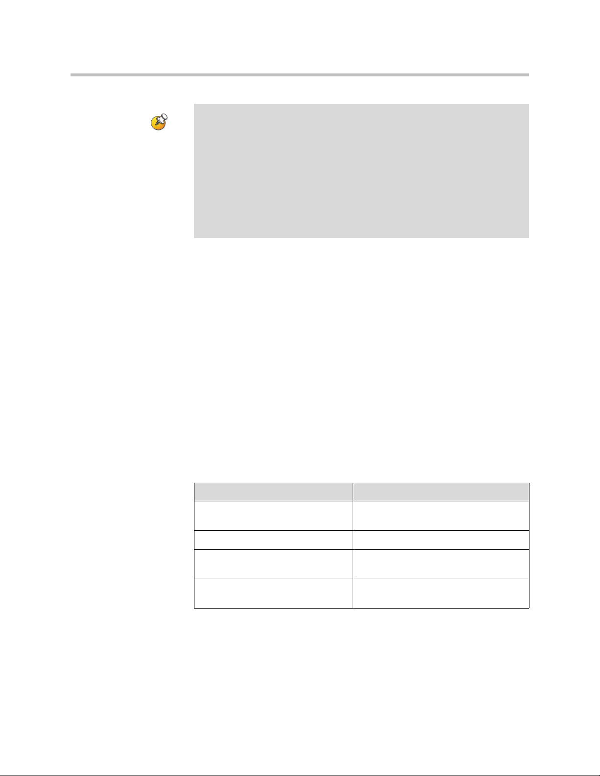
Configuring Network Use
Points to note about SIP:
The SIP protocol has been widely adapted for voice over IP communications and
basic video conferencing; however, many of the advanced video conferencing
capabilities are not yet standardized. Many capabilities also depend on the SIP
server.
Examples of features that are not supported using SIP are:
• Polycom Video and Audio Error Concealment
• Encryption
• People and Content (H.239 and Polycom People+Content)
• H.263 Pro-Motion
Integration with Microsoft Live Communications Server (LCS)
Integration with Microsoft LCS allows you to set up a list of LCS contacts, see
if the contacts are online, and call them without knowing or remembering their
addresses. Contacts appear in the directory and can also be displayed on the
home screen. For more information about the contact list home screen, refer to
Displaying Contacts on the Home Screen on page 4-50.
To configure a VSX system for use with Microsoft LCS:
1. Contact the LCS administrator to make sure that the VSX system has a
user account on the LCS server. Make a note of the account information.
2. Go to System > Admin Settings > Network > Call Preferences.
3. Select Enable SIP.
4. Go to System > Admin Settings > Network > IP > SIP Settings.
5. Configure these settings:
Setting Description
User Name Specifies the user name created for your
VSX system with the LCS server.
Password Specifies the password for this user name.
Registrar Server Specifies the location (IP or DNS) of the
LCS server.
Proxy Server Specifies the location (IP or DNS) of the
LCS server.
3 - 13
Page 70

Administrator’s Guide for the VSX Series
To view the status of the current LCS registration, do one of the following:
¾ Go to System > Admin Settings > Global Services > Directory Servers >
¾ Select the Microsoft LCS server icon at the top of the Directory screen.
Adding and Removing Microsoft LCS Contacts
To add or remove Microsoft LCS contacts that appear on the VSX system, you
must use Microsoft Office Communicator or Windows Messenger.
To add or remove LCS contacts for the VSX system:
1. Open the Microsoft Office Communicator or Windows® Messenger
2. Log in to the application using the account information from the SIP
3. Use the application to add or remove contacts for the VSX system.
Microsoft.
application on a computer.
Settings screen of the VSX system.
To configure display options for contact list information:
1. Go to System > Admin Settings > Global Services > Directory Servers >
Microsoft. You can also select the Microsoft LCS server icon at the top of
the Directory screen.
2. Configure these settings:
Setting Description
Display Contacts Specifies whether to display your contacts
on the contact list home screen and in the
directory. For more information, refer to
Displaying Contacts on the Home Screen
on page 4-50.
Show My Offline Contacts Specifies whether to include offline
contacts on the contact list home screen
or in the directory.
3 - 14
Page 71

Specifying Quality of Service
Set the Quality of Service options for the way your network handles IP packets
during video calls.
To specify Quality of Service:
1. Go to System > Admin Settings > Network > IP > Quality of Service.
2. Configure these settings:
Setting Description
Type of Service Specifies your service type and lets you choose how to set the
Configuring Network Use
priority of IP packets sent to the system for video, audio, and
far-end camera control:
• IP Precedence — Represents the priority of IP packets
sent to the system. The value can be between 0 and 5. If
this setting is selected, enter the value in the Ty pe of
Service Value field.
• DiffServ — Represents a priority level between 0 and 63. If
this setting is selected, enter the value in the Type of
Service Value field.
Type of Service
Value
Maximum
Transmission
Unit Size
Enable PVEC Allows the system to use PVEC (Polycom Video Error
Enable RSVP Allows the system to use Resource Reservation Setup Protocol
Specifies the IP Precedence or Diffserv value for Video, Audio,
and Far End Camera Control.
Specifies the Maximum Transmission Unit (MTU) size used in
IP calls. If the video becomes blocky or network errors occur,
packets may be too large; decrease the MTU. If the network is
burdened with unnecessary overhead, packets may be too
small; increase the MTU.
Concealment) if packet loss occurs.
(RSVP) to request that routers reserve bandwidth along an IP
connection path. Both the near site and far site must support
RSVP in order for reservation requests to be made to routers
on the connection path.
3 - 15
Page 72

Administrator’s Guide for the VSX Series
3. Select and configure these settings:
Setting Description
Dynamic
Bandwidth
Maximum
Transmit
Bandwidth
Maximum
Receive
Bandwidth
Specifies whether to let the system automatically find the
optimum line speed for a call.
Specifies the maximum transmit line speed between 64Kbps and
1920 Kbps.
Specifies the maximum receive line speed between 64Kbps and
1920 Kbps.
Configuring the System for Use with a Firewall or NAT
A firewall protects an organization’s IP network by controlling data traffic
from outside the network. Unless the firewall is designed to work with H.323
video conferencing equipment, you must configure the system and the
firewall to allow video conferencing traffic to pass in and out of the network.
Network Address Translation (NAT) network environments use private
internal IP addresses for devices within the network, while using one external
IP address to allow devices on the LAN to communicate with other devices
outside the LAN. If your system is connected to a LAN that uses a NAT, you
will need to enter the NAT Public (WAN) Address so that your system can
communicate outside the LAN.
3 - 16
To set up the system to work with a firewall or NAT:
1. Go to System > Admin Settings > Network > IP > Firewall.
2. Configure these settings:
Setting Description
Fixed Ports Lets you specify whether to define the TCP and UDP ports.
• If the firewall is not H.323 compatible, enable this
setting. The VSX system assigns a range of ports
starting with the TCP and UDP ports you specify. The
system defaults to a range beginning with port 3230 for
both TCP and UDP.
Note: You must open the corresponding ports in the
firewall. You must also open the firewall’s TCP port
1720 to allow H.323 traffic.
• If the firewall is H.323 compatible or the system is not
behind a firewall, disable this setting.
Page 73
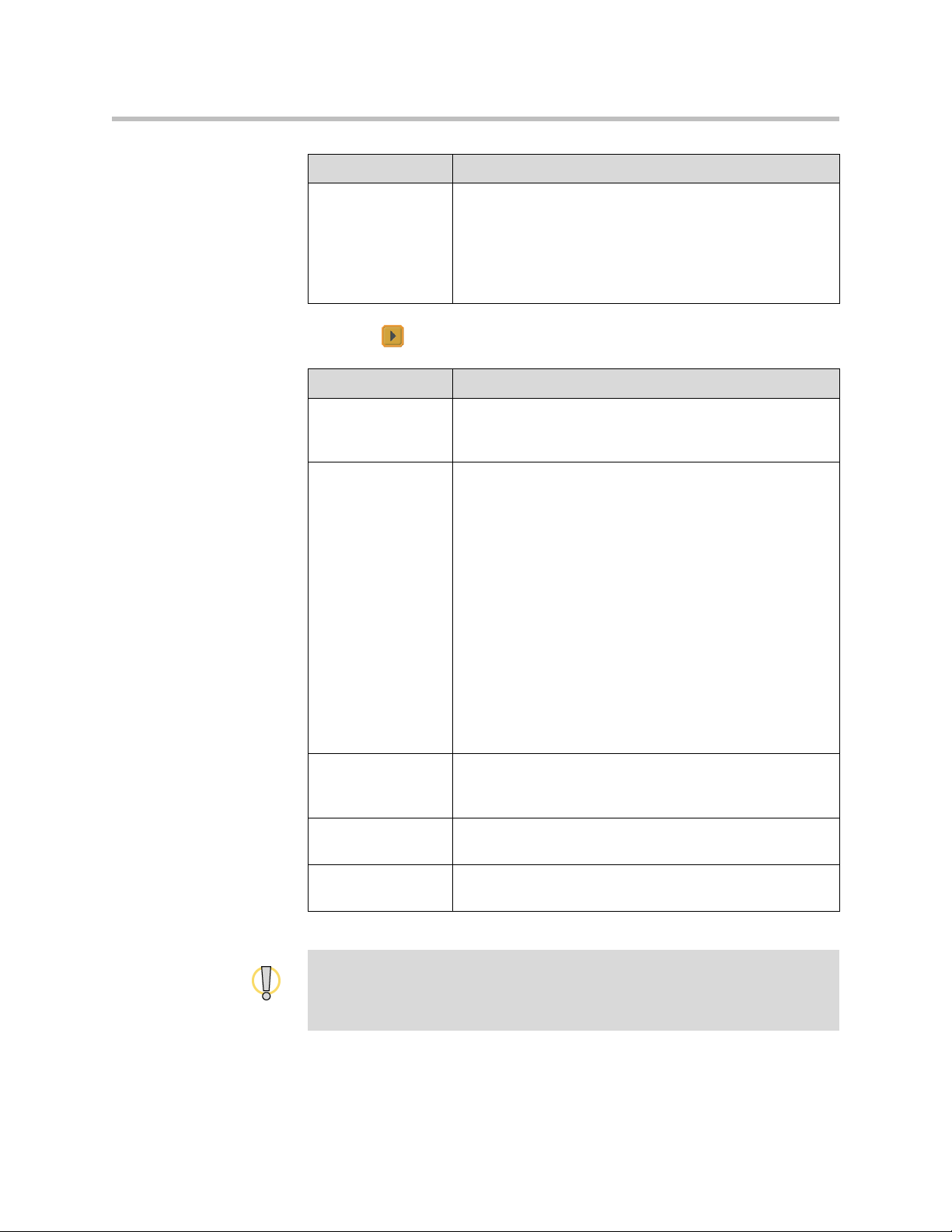
Setting Description
Configuring Network Use
TCP Ports
UDP Ports
Lets you specify the beginning value for the range of TCP
and UDP ports used by the system. The system
automatically sets the range of ports based on the
beginning value you set.
Note: You must also open the firewall’s TCP port 1720 to
allow H.323 traffic.
3. Select and configure these settings:
Setting Description
Enable
NAT/Firewall
Traversal
NAT Configuration Lets you specify whether the system should determine the
Allows the system to use H.460-based firewall traversal. For
more information, refer to H.460 NAT Firewall Traversal on
page 3-18.
NAT Public WAN Address automatically.
• If the system is behind a NAT that allows HTTP traffic,
select Auto.
• If the system is behind a NAT that does not allow HTTP
traffic, select Manual.
• If the system is not behind a NAT or is connected to the
IP network through a Virtual Private Network (VPN),
select Off.
• If the system is behind a firewalled NAT router that is
UPnP (Universal Plug and Play) certified, select UPnP.
Many routers used in homes and small businesses
support UPnP NAT traversal. If this is your situation, try
selecting UPnP first. If this selection does not work for
your router, select Auto or Manual.
NAT Public (WAN)
Address
Displays the address that callers from outside the LAN use
to call your system. If you chose to configure the NAT
manually, enter the NAT Public Address here.
NAT is H.323
Compatible
Address Displayed
in Global Directory
Specifies that the system is behind a NAT that is capable of
translating H.323 traffic.
Lets you choose whether to display this system’s public or
private address in the global directory.
Visit the Polycom Security Center at www.polycom.com for timely security
information. Systems deployed outside a firewall are potentially vulnerable to
unauthorized access. You can also register to receive periodic email updates and
advisories.
3 - 17
Page 74

Administrator’s Guide for the VSX Series
H.460 NAT Firewall Traversal
You can configure VSX systems to use standards-based H.460.18 and H.460.19
firewall traversal, which allows video systems to more easily establish IP
connections across firewalls.
The following illustration shows how a service provider might provide H.460
firewall traversal between two enterprise locations. In this example the V
2
IU™
traversal server gateway is on the edge of the service provider network and
facilitates IP calls between VSX systems behind different firewalls.
Service Provider
2
V
IU Server Gateway
that Supports H.460.18
and H.460.19
Enterprise Location A
IP Network
System with
Traversal Enabled
Gatekeeper
Enterprise Location B
System with
Traversal Enabled
To use this traversal, VSX systems and firewalls must be configured as follows:
3 - 18
• Enable firewall traversal on the VSX system.
• Register the VSX system to an external V
2
IU Traversal Server Gateway
that supports the H.460.18 and H.460.19 standards.
• Make sure that firewalls being traversed allow VSX systems behind them
to open outbound TCP and UDP connections.
— Firewalls with a stricter rule set should allow VSX systems to open at
least the following outbound TCP and UDP ports: 1720 (TCP),
14085-15084 (TCP) and 1719(UDP), 16386-25386 (UDP).
— Firewalls should permit inbound traffic to TCP and UDP ports that
have been opened earlier in the outbound direction.
• For best interoperability, make sure that H.323 protocol-aware features are
disabled on firewalls being traversed.
To enable firewall traversal on a VSX system:
1. Go to System > Admin Settings > Network > IP > Firewall > Next.
2. Select Enable NAT/Firewall Traversal.
Page 75

Configuring ISDN Support
You can add one optional network interface module to the VSX 5000,
VSX 7000, VSX 7000s, VSX 7000e, and VSX 8000 systems. This lets you extend
the functionality of the systems so that you can:
• Make ISDN calls over a BRI network.
• Make ISDN calls over a PRI/T1 network (in North America and Japan) or
PRI/E1 (outside of North America and Japan) with the VSX 7000,
VSX 7000s, VSX 7000e, or VSX 8000.
• Connect encryption or other third-party network equipment using a Serial
V.35/RS-449/RS-530 interface with the VSX 7000, VSX 7000s, VSX 7000e,
or VSX 8000.
The VSX 3000 or VSX 3000A (ISDN model) includes a BRI network interface
for ISDN calling.
The VSX 5000 with an optional BRI module supports ISDN calling.
This section describes the settings for all optional network interfaces and
identifies the settings that are available for specific network interfaces.
Configuring Network Use
You can configure a network interface option if the corresponding network
interface module is installed. The system automatically detects the type of
interface installed and displays only the required configuration screens.
Configuring the BRI Network Interface
To configure the ISDN network interface settings:
1. Go to System > Admin Settings > Network > ISDN.
2. Configure these settings:
Setting Description
Enable ISDN
H.320
Number of ISDN
Channels to
Dial in Parallel
Outside Line
Dialing Prefix
Numbering
Plan
Allows this system to make H.320 (ISDN) calls.
Specifies how many channels to dial at one time.
You can specify up to eight channels. If you experience
network problems, decrease the number.
Specifies the ISDN dialing prefix used to call outside the
network.
Select the appropriate numbering plan for your location, if it
differs from the default.
3 - 19
Page 76

Administrator’s Guide for the VSX Series
Setting Description
ISDN Switch
Protocol
ISDN Voice
Algorithm
Auto BRI
Configuration
Specifies the protocol used by your network’s switch.
Specifies which voice algorithm (aLaw or uLaw) is used for
ISDN voice calls.
Do not change this setting unless you experience audio issues
in all ISDN voice calls.
Allows the NI-1 switch to automatically configure the directory
numbers and SPIDs.
This setting is only available if you have selected the NI-1
switch protocol.
3. Select and configure these settings:
Setting Description
Area Code Specifies the area code for this system’s location.
Directory
Numbers
Enable Specifies whether to enable the associated ISDN line.
Specifies the numbers assigned to the B1 and B2 channels for
each BRI line.
The two numbers for a line may be the same or different,
depending on the switch protocol in use.
If you selected Standard ETSI Euro-ISDN protocol, you must
enable all BRI lines that you expect to be active, and you must
not enable lines that will not be connected.
You may want to disable a particular line if there are problems
with the line that generate continuing error messages.
3 - 20
The ISDN BRI Numbers screen also displays the country selected as the
system’s location and the country code used for international calls to the
system. To specify the system’s location, go to System > Admin Settings
> General Settings > Location. The system automatically supplies the
country code when you specify the country.
4. If you have configured the
ISDN switch protocol to be AT&T 5ESS
Multipoint, NI-1, or Nortel DMS-100, select and enter the ISDN BRI
SPIDs provided by your service provider.
After you enter the SPIDs, the system verifies them. If the system is unable
to verify the SPIDs, make sure the system is connected and that the ISDN
numbers you entered are correct.
If you do not have the SPIDs from your service provider, you can click
Start to Auto Detect SPIDs.
Page 77

Configuring the PRI Network Interface
To use the PRI network interface, you must configure the following:
• PRI network support
• PRI channels
• PRI information
Your ISDN service provider can tell you which protocol your network uses. If
you later change the Country setting, the PRI switch protocols available may
also change, and you may be prompted to configure a different PRI switch
protocol.
Points to note about fractional PRI:
• Assigned channels must begin with channel 1, and the channel numbers must
be consecutive.
• A D channel must be provided.
• Outbound call bandwidth must not exceed the available bandwidth.
Configuring Network Use
To configure the ISDN network interface settings:
1. Go to System > Admin Settings > Network > ISDN.
2. Configure these settings:
Setting Description
Enable ISDN
H.320
Area Code Specifies the area code for this system’s location.
PRI Video
Number
Outside Line
Dialing Prefix
BONDING:
Calling Endpoint
Uses the Original
ISDN Number
Allows this system to make H.320 (ISDN) calls.
Specifies the ISDN number assigned to this system.
Specifies the ISDN dialing prefix used to call outside the
network.
Specifies the use of a bonding standard. Incoming bonded
calls will use the original number received to connect all
remaining lines required for the call.
3 - 21
Page 78

Administrator’s Guide for the VSX Series
3. Select and configure these settings:
Setting Description
Line Signaling Specifies the framing format in use.
This setting is configurable for PRI E1, read-only for PRI T1.
External CSU
North America only
Line Build Out
PRI T1 only
Specifies whether this system uses an external or internal
Channel Service Unit (CSU).
For systems using an internal CSU, indicates the output
attenuation in dB. Your service provider can provide you with
these values.
For systems using an external CSU, indicates the length (in
feet) of the RJ-45 cable that connects the PRI network
interface module to the CSU.
Switch Protocol Specifies the Network switch protocol. The available choices
are determined by the system’s country settings.
This setting is read-only for PRI E1, configurable for PRI T1.
ISDN Voice
Algorithm
Specifies which voice algorithm (aLaw or uLaw) is used for
ISDN voice calls.
Do not change this setting unless you experience audio
issues in all ISDN voice calls.
4. Select and configure these settings:
Setting Description
Numbering Plan Select the appropriate numbering plan for your location, if it
differs from the default.
3 - 22
International
Specify the dialing prefix needed for international calls.
Dialing Prefix
Call-by-Call Specifies a code that the system sends to the telephone
company switch to request a special service, if such a code is
required.
Consult your telephone service provider to determine the
proper call-by-call value.
Number of ISDN
Channels to Dial
in Parallel
Specifies how many channels to dial at one time.
You can specify up to eight channels. If you experience
network problems, decrease the number.
Set this value to 1 for serial dialing. Serial dialing is not
recommended unless you have trouble connecting calls using
parallel dialing.
Restore Defaults Resets all values on this screen. This does not affect other
PRI settings.
Page 79

Configuring Network Use
To access PRI Information:
1. Go to System > Admin Settings > Network > ISDN.
2. Select three times to go to the ISDN PRI Info screen where you can
view the following read-only information:
Setting Description
PRI Line Type Displays read-only information about the system
Number of Active Channels
D Channel Location
Network Mode
Clock Source
Terminal Endpoint ID
TEI
Line Termination
PRI E1 only
and its configuration.
To configure the PRI channels:
1. Go to System > Admin Settings > Network > ISDN.
2. Select four times to go to the ISDN PRI Status screen.
3. Select a channel to activate or deactivate it. Active channels are
represented by a green icon, and inactive channels are represented by a
gray icon.
Make sure that channels are activated and deactivated only by a knowledgeable
network professional so that the system operates properly and can dial at the
desired rates.
3 - 23
Page 80
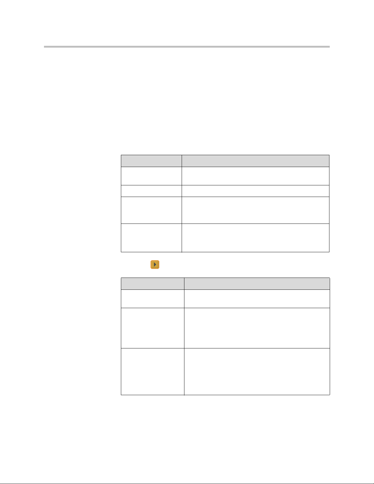
Administrator’s Guide for the VSX Series
Configuring the Serial V.35/RS-449/RS-530 Network Interface
If you have a VSX 7000, VSX 7000s, VSX 7000e, or VSX 8000 system, the
optional serial V.35/RS-449/RS-530 network interface allows you to connect
to data communications equipment using a V.35, RS-449, or RS-530 serial
interface.
To configure the V.35/RS-449/RS-530 network interface settings:
1. Go to System > Admin Settings > Network > V.35/RS-449/RS-530.
2. Configure these settings:
Setting Description
Enable
V.35/RS-449/RS-530
V.35 Ports Used Specifies whether one or two lines are connected.
RS-366 Dialing Allows users to dial calls from this system.
Area Code
Port 1
Port 2
Allows the system to connect to a terminal adapter using
a V.35, RS-449, or RS-530 connection.
Clear this setting if this is a dedicated connection or if
another device is used for dialing calls.
Specifies the area code and number(s) that other sites
dial to reach this system.
If this is a dedicated connection, leave these fields blank.
3. Select and configure these settings:
Setting Description
Prefix Lets you specify the dialing prefix required to reach an
outside line.
Calling Profile Lets you specify what data communications equipment is
connected to the network interface. The system
automatically displays the default prefixes, suffixes, and
calling speeds required by that device.
If your device is not listed, select Custom.
3 - 24
Speed Lets you define the prefixes or suffixes to use for each
speed used in a Custom Calling Profile. For information
about required prefixes and suffixes, see the
documentation that came with the device.
If you choose a predefined Calling Profile, this
information is supplied for you.
Page 81

Configuring Network Use
4. Select and configure these settings:
Setting Description
ST Lets you specify the signaling required by the external
RT
RTS
CTS If your system is connected to Ascend equipment, you
DSR
DCD
DTR
Answer on DSR Specifies that the system should begin the call when it
device connected to the system. Specify normal or
inverted, as appropriate. In most cases, normal signaling
is appropriate.
may need to set CTS to Ignore.
detects a DSR signal.
Delayed DCD
Hangup
DTR Pulse Duration
(secs)
Trigger Call on H.320
Data
Specifies how long the system waits to end the call after
a DCD signal is lost (for example, during a call via
satellite).
Specifies how long the DTR signal goes low after the far
site hangs up. When the pulse is too short, the call may
not clear.
If your system is connected to ADTRAN equipment, you
may need to adjust DTR pulse duration.
Specifies whether the call starts when H.320 data is
detected at the V.35 interface while set for direct
connect.
3 - 25
Page 82
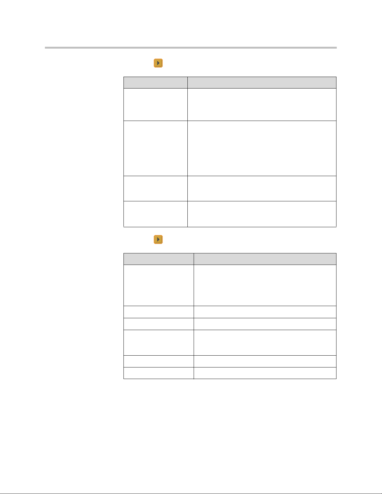
Administrator’s Guide for the VSX Series
5. Select and configure these settings:
Setting Description
Crypto Resync Allows a VSX system connected to cryptographic
equipment to signal when it loses video synchronization
during a call. The cryptographic equipment can then
resynchronize with the far site.
Use RTS Signal for
Resync Pulse
Allows the system to send the resynchronization pulse on
the RTS signal. Select this setting if your data
communications equipment uses the V.35 or RS-449
capability of the serial V.35/RS-449/RS-530 network
interface.
Note: When you select this setting, the RTS no longer
functions as the Request To Send signal.
Time Between
Pulses (sec)
Specifies whether the system should set the time
between resync pulses automatically or use the number
of seconds you enter.
Pulse Width
(millisec)
Specifies whether the system should set the pulse
duration automatically or use the number of milliseconds
you enter.
6. Select and configure these settings:
Setting Description
Enable Broadcast
Mode
Enables support for H.331 broadcast transmissions
from the VSX system.
Broadcast mode enables the system to send video
and audio to many other systems, such as large
satellite networks.
3 - 26
Enable People+Content Enables People+Content for broadcast mode.
Video Format Specifies the resolution at which video is transmitted.
Video Protocol Specifies the protocol used to transmit video. Choose
the lowest protocol supported by all systems in the
conference.
Audio Protocol Specifies the protocol used to transmit audio.
Frame Rate Specifies the frame rate to use.
Page 83

Configuring Telephony with the SoundStation VTX 1000
You can use a SoundStation VTX 1000 conference phone with set-top and
component systems to place, add, or redial video calls, or to add video to audio
calls. To take advantage of the latest integration features, the VSX system
requires version 7.5 or later software and the SoundStation VTX 1000 requires
version 1.5 or later software.
You can connect an analog phone line to the VSX 7000e or VSX 8000 to make
regular telephone calls with the system or to add audio-only participants to
video calls.
To configure telephony options:
1. Go to System > Admin Settings > Network > Telephony.
2. Configure these settings:
Setting Description
Configuring Network Use
Room Telephone
Number
System Telephone
Number
VSX 7000e
VSX 8000
VTX Telephone
Number
VSX 5000
VSX 6000
VSX 6000A
VSX 7000
VSX 7000s
VSX 7000e
VSX 8000
Outside Line
Dialing Prefix
Enter the telephone number of the room where the system
is located.
Specifies the analog phone number of the system, including
country and area codes for the system’s location.
Specifies the number of the SoundStation VTX 1000
conference phone that is connected to the system.
Specifies the dialing prefix used to call outside the network.
3 - 27
Page 84
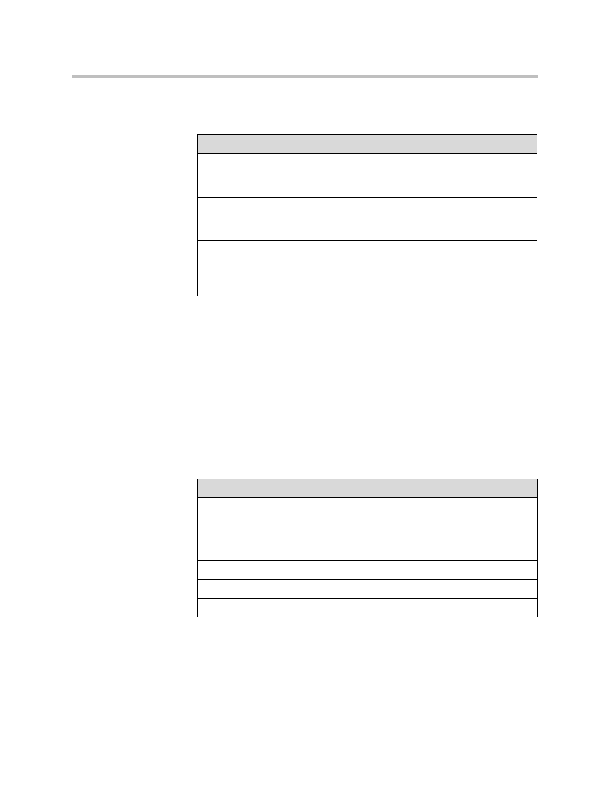
Administrator’s Guide for the VSX Series
To configure the analog phone line (POTS line) for the VSX 7000e or VSX 8000
system:
Go to this screen: Configure these settings:
Telephony
System > Admin Settings >
Network > Telephony
Call Preference
System > Admin Settings >
Network > Call Preference
Network Dialing
System > Admin Settings >
Network > Call Preference >
Next
Configuring Call Preferences
Call preferences help you manage the network bandwidth used for calls. You
can specify the default and optional call settings for outgoing calls. You can
also limit the call speeds of incoming calls.
To choose call preferences:
1. Go to System > Admin Settings > Network > Call Preference.
Enter the System Telephone Number for the
analog phone line.
Enable Analog Phone.
Add Analog Phone to the Dialing Order
3 - 28
2. Configure these settings:
Setting Description
Enable Basic
Mode
Enable H.239 Specifies standards-based People+Content data collaboration.
Enable IP H.323 Allows the system to make IP calls.
Enable SIP Allows the system to use SIP when connecting IP calls.
Enables a limited operating mode that uses H.261 for video
and G.711 for audio. This mode provides administrators with a
workaround for interoperability issues that cannot be solved
using other methods. The Basic Mode setting stays in effect
until you change it.
Page 85
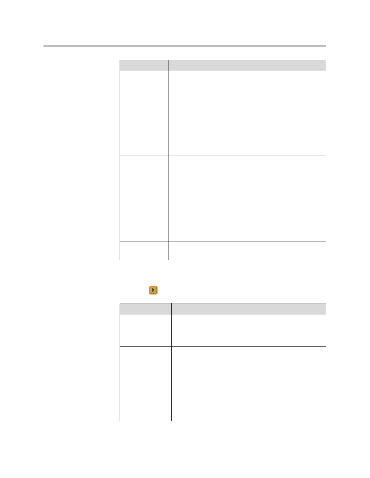
Setting Description
Configuring Network Use
Enable ISDN
H.320
VSX 3000
VSX 3000A
VSX 7000
VSX 7000s
VSX 7000e
VSX 8000
Enable Voice
Over ISDN
Enable
V.35/RS-449/
RS-530
VSX 7000
VSX 7000s
VSX 7000e
VSX 8000
Enable Analog
Phone
VSX 7000e
VSX 8000
Enable ISDN
Gateway
Allows the system to make ISDN calls.
This selection is only available when the system has ISDN
networking capability.
Allows the system to make voice-only calls to phones
connected to an ISDN network, such as an organization’s
PBX.
Allows the system to make calls through your third-party
network equipment.
This selection is only available when the system has a
V.35/RS-449/RS-530 network module installed.
Allows the system to make voice-only calls to any phone using
an analog phone line.
Disable this setting to remove a SoundStation VTX 1000
conference phone from the dialing order.
Allows users to choose whether to place IP-to-ISDN calls
through a gateway.
To make the enabled call types available on the Place a Call screen, you must
enable the Call Quality setting described on page 4-48.
1. Select and configure these settings:
Setting Description
Preferred Dialing
Method
Specifies the preferred method for dialing various call types. If
set to Auto, calls use the configured Dialing Order. If set to
Manual, the system prompts the user to select the call type
from a list when placing a call.
Dialing Order Specifies how the system places calls to directory entries that
have both IP and ISDN numbers. It also specifies how the
system places calls dialed manually, when the call type
selection is either unavailable on the home screen or set to
Auto. If a call attempt does not connect, the system tries to
place the call using the next call type in the Dialing Order.
This setting is available only when Preferred Dialing Method
is set to Auto.
For more information, refer to Configuring Dialing Order
Settings on page 3-30.
3 - 29
Page 86

Administrator’s Guide for the VSX Series
2. Select to go to the Preferred Speeds screens and configure these
settings:
Setting Description
Preferred Speed
for Placing Calls
Maximum Speed
for Receiving
Calls
3. Select to go to the Call Speeds screen and specify the call speeds to
make available to users, if you are allowing them to choose speeds on a
call-by-call basis.
Configuring Dialing Order Settings
If the call type on the home screen is set to a specific call type, the system does
not attempt to place the call using a different call type, even if other types are
listed in the Dialing Order.
Determines the speeds that will be used for calls from this
system when:
• Call Quality is set to Auto on the home screen and
Directory screen, or
• The Call Quality setting is not available for users.
If the far-site system does not support the selected speed, the
system automatically negotiates a lower speed.
Allows you to restrict the bandwidth used when receiving
calls.
If the far site attempts to call the system at a higher speed
than selected here, the call is re-negotiated at the speed
specified in this field.
3 - 30
You can configure the VSX system so that users can choose to place IP-to-ISDN
or ISDN-to-IP calls through a gateway.
To allow users to place an IP-to-ISDN call through a gateway:
1. Make sure the system is registered with a gatekeeper.
2. Go to System > Admin Settings > Network > Call Preference and select
Enable ISDN Gateway.
3. If you want to allow users to place IP-to-ISDN calls through a gateway
when calling from the directory, do one of the following:
— On the Network Dialing screen, set Preferred Dialing Method to
Auto and select ISDN Gateway as the first choice under Dialing
Order. With this configuration, calls placed from the directory will be
placed through a gateway first if an ISDN number exists.
— On the Network Dialing screen, set Preferred Dialing Method to
Manual. With this configuration, users can select ISDN Gateway
from the list of call types that appears when placing a call from the
directory.
Page 87

Configuring Network Use
To allow users to place an ISDN-to-IP call through a gateway:
1. If you want to allow users to place ISDN-to-IP calls through a gateway
when dialing manually:
a. Make sure Call Quality is enabled on the Home Screen Settings
screen. This setting displays the Call Type selection on the Place a Call
screen.
b. On the Network Dialing screen, select IP Gateway next to ISDN in the
Dialing Order.
With this configuration, users can enter the gateway address in the dialing
field, along with an extension in extension field, and select IP H323 in the
call type list.
2. If you want to allow users to place ISDN-to-IP calls through a gateway
when calling from the directory, do one of the following:
— On the Network Dialing screen, set Preferred Dialing Method to
Auto and select IP Gateway next to ISDN under Dialing Order. With
this configuration, calls placed from the directory will be placed
through a gateway first if a gateway address is present in the ISDN
number field and an extension is present in the Extension field.
— On the Network Dialing screen, set Preferred Dialing Method to
Manual. With this configuration, users can select IP Gateway from
the list of call types that appears when placing a call from the
directory.
Configuring the Global Directory
If your organization uses the Polycom Global Management System™, you can
configure your system to use the global directory. The global directory
provides a list of other systems that are registered with the Global Directory
Server and available for calls. The other systems appear in the directory,
allowing users to place calls to other users by selecting their names.
Configuring the Directory Server Settings
To configure the Directory Server settings:
1. Go to System > Admin Settings > Global Services > Directory Servers.
2. Configure these settings:
3 - 31
Page 88
Administrator’s Guide for the VSX Series
Setting Description
Global Directory
(GDS)
Password Lets you enter the global directory password, if there is one.
Register Registers this system with the Global Directory Server.
Display Global
Addresses
Display Name in
Global Directory
Save Global
Directory to
System
Group Name Specifies the group name used for global directory entries in
Setting the Dialing Rules
If your system is connected to your organization’s private network and also to
a public network, you may need to specify the codes and prefixes necessary for
dialing other systems.
Specifies the IP address or DNS address of the Global
Directory Server. You can enter up to five addresses.
Displays other registered systems in the global directory.
Specifies whether to display the system’s name in the Global
Directories of other registered systems.
Copies the global directory to this local system. When this
setting is disabled, the system can display no more than 1,000
global directory entries. When this setting is enabled, the
system can display up to 4,000 global directory entries.
the local directory. In the directory, entries from Global
Directory Servers are listed in the Polycom GDS group.
3 - 32
To set the dialing rules:
1. Go to System > Admin Settings > Global Services > Dialing Rules.
2. Configure these settings:
Setting Description
Always Dial Area
Code
Dial 1+ for all USA
calls
Specifies that calls to sites in the same area code must
include the area code.
Specifies that calls to systems in the United States must
include a “1” before the area code.
Note: Even if you have this setting enabled, you may need
to dial 1 and the area code when calling long distance over
ISDN within your same area code.
Page 89

Placing a Test Call
When you finish configuring the system, you can use one of the sample
numbers in the directory to test your setup.
To place a test call:
1. On the Place a Call screen, select Directory.
2. Select Group.
3. Select Sample Sites and highlight a location.
4. Press Call on the remote control.
You can also find a list of worldwide numbers that you can use to test your
VSX system at www.polycom.com/videotest.
If you have trouble making video calls:
• Make sure the number you dialed is correct, then try the call again. For
Configuring Network Use
example, you may need to dial 9 for an outside line or include a long
distance access code or country code.
• To find out if the problem exists in your system, ask the person you were
trying to reach to call you instead.
• Find out if the system you are calling has its power turned on and is
functioning properly.
• If you can make calls but not receive them, make sure that your system is
configured with the correct number.
Checking System Status
The System Status screen provides detailed information about system
settings, IP and ISDN connections, time server connections, and other
information that is important to the functioning of the system. For an
explanation of any of the status items, select the item and press on the
remote.
When there is a change in system status or a potential problem, you see an alert
at the bottom of the Place a Call screen.
To view System Status information:
¾ Go to System > Diagnostics > System Status.
3 - 33
Page 90

Administrator’s Guide for the VSX Series
To get information about a status message:
¾ Select the status message and press or on the remote control.
Keeping your Software Current
If you have Internet access and a software key, you can use the web-based
Softupdate application to update the VSX Series software. If you do not have
Internet access, your reseller can supply you with the VSX Series software
update on CD-ROM.
Do not power off the system during the software upgrade process. If the upgrade is
interrupted, the system may become unusable.
To update your software via the Internet:
1. Using a web browser, go to www.polycom.com/videosoftware and log
in to the Polycom Resource Center.
You will need to set up a PRC account, if you don’t already have one.
2. Navigate to your product page.
Refer to the Release Notes for information about the latest software version.
Refer to Upgrading Polycom Video Software for detailed information about
obtaining software key codes and using the SoftUpdate program.
3. Download the VSX Series software update file in .zip format.
4. Double-click the software.zip file to extract the file.
5. Double-click Softupdate.exe to run the update program.
If you install version 8.5 or later on a VSX system that has Security Mode enabled,
the system verifies that the software being installed is authentic Polycom software.
To install a version earlier than 8.5, you must disable Security Mode on the VSX
system.
3 - 34
Page 91

Customizing the VSX System
Every organization has users with different needs. With a VSX system, you can
design the video conferencing experience to meet the needs of everyone.
You can customize the look and behavior of the system, and then build in the
required access levels for your users, depending on how much or how little
you want them to change system behaviors.
When you set up the system for the first time, the system is configured with
the most commonly used settings. If you need to change any of these initial
settings, you can adjust the screen settings as described in this chapter.
If you established an administrator’s password during the initial
configuration, you must enter it each time you access advanced settings.
4
Designing Video Behaviors
You can configure the following video behaviors to accommodate your
environment:
• Camera Settings and Video Quality
• Monitors
• Content Display
• VCR/DVD Player Settings
4 - 1
Page 92

Administrator’s Guide for the VSX Series
Configuring Camera Settings and Video Quality Options
The Cameras and Video Quality screens let you specify camera and video
settings, as appropriate for the equipment you are using.
To configure camera and video settings:
1. Go to System > Admin Settings > Cameras.
2. Configure these settings:
Setting Description
Far Control of
Near Camera
VSX 5000
VSX 6000
VSX 6000A
VSX 7000
VSX 7000s
VSX 7000e
VSX 8000
Backlight
Compensation
Camera
Brightness
VSX 3000
VSX 3000A
VSX 5000
Primary Camera Specifies which camera is the main camera.
Camera Direction
VSX 5000
VSX 6000
VSX 6000A
VSX 7000
VSX 7000s
VSX 7000e
VSX 8000
Specifies whether the far site can control the position of the
near-site camera. When this option is selected, a user at the
far site can control the framing and angle of the camera for
the best view of the near site.
Specifies whether to have the camera automatically adjust
for a light background. Backlight compensation is best used
in situations where the subject appears darker than the
background.
Specifies how much light is let into the camera’s iris. A low
number allows in less light; a high number allows in more
light.
Specifies the direction the camera moves when using the
arrow buttons on the remote control.
4 - 2
Power
Frequency
VSX 3000
VSX 3000A
VSX 5000
Specifies the frequency of the electrical power used for the
camera.
• 50 Hz—Select if you have a PAL system.
• 60 Hz—Select if you have an NTSC system.
Page 93

Setting Description
Customizing the VSX System
VCR/DVD Audio
Out Always On
VSX 7000s
VSX 7000e
VSX 8000
Allows you to record a call using one VCR or DVD, while
playing recorded content into the call from a second VCR or
DVD.
Do not select this setting if you have only one VCR or DVD
player connected.
3. Select to go to Camera Settings:
— Specify the name, icon, and format for each video source.
— VSX 6000, VSX 7000, VSX 7000s, VSX 7000e, VSX 8000: Specify
whether secondary camera sources are People or Content. Camera
sources specified as Content are sent at a higher resolution and lower
frame rate.
4. Select to go to Video Quality.
5. Select Motion or Sharpness for the video inputs:
—Motion — This setting is for showing people or other video with
motion.
—Sharpness — The picture will be sharp and clear, but motion will not
be smooth. Choose this setting for document cameras. Sharpness is
available in point-to-point H.263 calls only.
6. Set Pro-Motion Video to specify when to use Pro-Motion for video
inputs set for motion. Pro-Motion provides 50/60 fields per second
interlaced video for TV-like quality at higher bandwidths.
— VSX 3000 and VSX 3000A systems send Pro-Motion video for the
DVD/VCR input only.
— VSX 5000, VSX 6000, and VSX 6000A systems can receive Pro-Motion
video but cannot transmit it.
7. Select to go to Camera Calibration. Only VSX 7000e and VSX 8000
systems with a PowerCam Plus camera can be calibrated for automatic
camera tracking. Follow the instructions on the screen to calibrate the
camera for automatic camera tracking if it consistently moves too far in
one direction when tracking is enabled. Press Near on the remote
control so that you can zoom the camera in on your mouth.
For the best calibration results, make sure the camera and system are set up as
described in Configuring Automatic Camera Tracking on page 4-4 and Connecting
Cameras to Component Systems on page 2-15.
4 - 3
Page 94

Administrator’s Guide for the VSX Series
To configure a second camera:
Go to this screen: Configure these settings:
Cameras
System > Admin Settings >
Cameras
Camera Settings
System > Admin Settings >
Cameras > Next
Video Quality
System > Admin Settings >
Cameras > Next > Next
Serial Port
VSX 7000,VSX 7000s,
VSX 7000e, VSX 8000
System > Admin Settings >
General Settings > Serial Port
• Designate this as the Primary Camera, if
desired.
• Set Camera Direction to specify which way
the camera moves when you control it with
the remote control. (VSX 5000, VSX 6000,
VSX 6000A, VSX 7000, VSX 7000s,
VSX 7000e, VSX 8000)
1. Name the camera.
2. Select a camera icon.
3. If you used an RCA to mini-DIN adapter to
connect the camera cable, change the Video
Format to Composite. (VSX 5000,
VSX 7000, VSX 7000s, VSX 7000e,
VSX 8000)
Set the video quality (Motion for people video or
Sharpness for still images).
If it is a PTZ camera:
1. Set the RS-232 Mode to Sony PTZ camera
control.
2. Specify which camera is associated with this
port.
4 - 4
Configuring Automatic Camera Tracking
You can configure a VSX 7000e or VSX 8000 with a Polycom PowerCam Plus
to track to the speaker’s voice or to camera presets. During a call, users can
press Auto on the remote control to toggle between Automatic Camera
Tracking, Automatic Camera Tracking to Presets, and Automatic Camera
Tracking Off.
When Automatic Camera Tracking to Presets is enabled and no one speaks for
30 seconds, the camera automatically moves to preset 0. When Automatic
Camera Tracking is enabled and no one speaks for 30 seconds, the camera
automatically moves to a position to include all of the people who have
spoken.
If the camera consistently moves too far in one direction when tracking is
enabled, follow the instructions on the Camera Calibration screen to calibrate
the camera for better tracking.
Page 95

Customizing the VSX System
Points to note about using automatic camera tracking:
• You must have a VSX 7000e or VSX 8000 with a Polycom PowerCam Plus
camera.
• If you are using Polycom microphones, make sure they are properly connected
and unmuted, and that the Enable Polycom Microphones and Echo
Canceller settings are selected.
• If you are using a Polycom Vortex, disable the Enable Polycom Microphones
and Echo Canceller settings.
• Disable the Enable Polycom StereoSurround setting.
For more information about setting up the PowerCam Plus for automatic
camera tracking, refer to the section Connecting Cameras to Component
Systems on page 2-15.
Configuring Camera Presets
Camera presets are stored camera positions that you can create ahead of time
or during a call.
Presets allow users to:
• Automatically point a camera at pre-defined locations in a room.
• Select a video source such as a VCR or DVD player, a document camera,
or an auxiliary camera.
If your system’s main camera supports electronic pan, tilt, and zoom
movement, you can create up to 100 preset camera positions for the near site.
Each preset stores the camera number, its zoom level, and the direction it
points (if appropriate). Near-site presets are available for VSX set-top and
component systems. They remain in effect until you delete or change them.
To store a preset:
1. If you are in a call, press Near or Far on the remote control to
choose a near-site or far-site camera or other video source.
2. If you selected a camera that supports electronic pan, tilt, and zoom, you
can adjust the camera’s position:
— Press the arrow buttons on the remote control to move the camera up,
down, to the left, or to the right.
— Press Zoom to zoom the camera out or in.
3. Press Preset on the remote control.
4 - 5
Page 96

Administrator’s Guide for the VSX Series
4. Press and hold a number to store the preset position.
To delete all presets:
1. If a call is connected, press Near to choose a near-site video source.
2. Press Preset on the remote control.
3. Press Delete to delete all presets.
Configuring Monitors
The VSX system allows you to customize displays to suit your room and
equipment configuration, including choosing the monitor for presenting
content.
To store a double-digit preset (10-99), hold the second number down.
Any existing preset stored at the number you enter is replaced.
If Automatic Camera Tracking to Presets will be used during calls, set
preset 0 to a wide shot of the room. When Automatic Camera Tracking to
Presets is enabled and no one speaks for 30 seconds, the camera
automatically moves to preset 0.
To configure monitors:
1. Go to System > Admin Settings > Monitors > Monitors.
2. Configure these settings:
4 - 6
Page 97

Setting Description
Customizing the VSX System
Monitor 1
VSX 5000
VSX 6000
VSX 6000A
VSX 7000
VSX 7000s
VSX 7000e
VSX 8000
Specifies the monitor’s aspect ratio:
•4:3 — Select if you are using a regular TV monitor.
•16:9 — Select if you are using a wide-screen monitor.
Specifies the monitor’s format:
•S-Video — Select if the main monitor is connected to a
VSX 8000 system using an S-Video cable.
• Composite — Select if the main monitor is connected to a
VSX 8000 system using a composite video cable and S-Video
to RCA adapter.
•VGA — Select if you are using a VGA monitor as the primary
display device for a VSX 5000, VSX 6000A, VSX 7000s,
VSX 7000e, or VSX 8000. If you select VGA, your VGA
monitor must be set to SVGA (800 x 600) or XGA (1024 x 768)
at 60 Hz, and Monitor 2 is disabled.
Note: If you select 16:9, you will also need to set up the monitor
for full-screen display. In the monitor’s setup menu, choose the
setting that stretches the picture uniformly without clipping the
edges, which is usually called Full, Wide screen, or 16x9.
Use this setting: Not this setting:
Output upon
Screen Saver
Activation
VSX 5000
VSX 6000
VSX 6000A
VSX 7000
VSX 7000s
VSX 7000e
VSX 8000
Specifies the screen saver output for Monitor 1:
Specifies whether black video or no signal is sent to the monitor
when the system goes to sleep and the screen saver activates.
Select Black if you want to display screen saver text or a screen
saver news feed. This is the recommended setting to prevent
burn-in for TV monitors.
Select No Signal if you want the display to react as if it is not
connected when the system goes to sleep. This is the
recommended setting for VGA monitors and projectors.
4 - 7
Page 98

Administrator’s Guide for the VSX Series
Setting Description
Monitor 2
VSX 5000
VSX 6000
VSX 6000A
VSX 7000
VSX 7000s
VSX 7000e
VSX 8000
Output upon
Screen Saver
Activation
VSX 5000
VSX 6000
VSX 6000A
VSX 7000
VSX 7000s
VSX 7000e
VSX 8000
Specifies the second monitor’s aspect ratio:
•Off — Select if you do not have a second monitor.
•4:3 — Select if you are using a regular TV monitor as the
second monitor.
•16:9—Select if you are using a wide-screen monitor as the
second monitor. On the monitor, select the display mode that
uniformly stretches the video from side to side, which is
usually called Full, Wide screen, or 16x9.
Specifies the second monitor’s format:
•S-Video — Select if you have a second monitor connected to
the system’s S-Video output using an S-Video cable.
• Composite — Select if you have a second monitor connected
to the system using a composite video cable.
•VGA — Select if you are using a VGA monitor as the second
display device.
Specifies the screen saver output for Monitor 2:
Specifies whether black video or no signal is sent to the monitor
when the system goes to sleep and the screen saver activates.
Select Black if you want to display screen saver text or a screen
saver news feed. This is the recommended setting to prevent
burn-in for TV monitors.
Select No Signal if you want the display to react as if it is not
connected when the system goes to sleep. This is the
recommended setting for VGA monitors and projectors.
4 - 8
VCR
VSX 7000s
VSX 7000e
VSX 8000
Specifies the VCR/DVD Player output format:
•S-Video — Select if you have a VCR or DVD player
connected to the system’s S-Video output using an S-Video
cable.
• Composite — Select if you have a VCR or DVD player
connected to the system output using a composite video
cable.
PIP Specifies PIP (Picture-in-Picture) behavior:
•Camera — The PIP window is displayed when the call is first
connected and when a user moves the camera, uses presets,
or switches to a different camera source.
•On — The PIP window stays on for the duration of the call.
• Off — The PIP window is not displayed during the call.
•Auto — The PIP window is displayed when a user picks up
the remote.
Note: PIP settings are also available in the User Settings screen.
Users can turn the PIP on or off and change its location on the
screen using
PIP on the remote control.
Page 99
Setting Description
Customizing the VSX System
Zoom Video
to Fit Screen
VSX 5000
VSX 6000
VSX 6000A
VSX 7000
VSX 7000s
VSX 7000e
VSX 8000
Display Icons
in a Call
Snapshot
Timeout
Dual Monitor
Emulation
Specifies whether the video image is displayed full screen on a
wide-screen monitor.
If this setting is enabled, video is shown full screen with a portion
of the top and bottom clipped off. If this setting is disabled, video
is centered with black margins on each side.
This setting applies to either Monitor 1 or Monitor 2, if they are set
to 16:9. This setting does not apply if Dual Monitor Emulation is
enabled.
Specifies whether to display all on-screen graphics, including
icons and help text, during calls.
Lets you choose whether to have slides and snapshots time out,
after a period of four minutes.
Specifies whether the system can show multiple views on a single
display. If content is being viewed, different views can be
displayed by pressing
PIP on the remote control.
For more information, refer to Using Dual Monitor Emulation on
page 4-11.
4 - 9
Page 100

Administrator’s Guide for the VSX Series
3. Select and configure these settings:
Setting Description
Monitor 1
VSX 5000
VSX 6000
VSX 6000A
VSX 7000
VSX 7000s
VSX 7000e
VSX 8000
Monitor 2
VSX 5000
VSX 6000
VSX 6000A
VSX 7000
VSX 7000s
VSX 7000e
VSX 8000
Visual
Concert VGA
Out
VSX 5000
VSX 6000
VSX 6000A
VSX 7000
VSX 7000s
Select the video source(s) to display on Monitor 1. For more
information about how this setting can affect your display, refer to
Video Source Output Examples for Multiple Monitors on page
Appendix-1.
Select the video source(s) to display on Monitor 2. For more
information about how this setting can affect your display, refer to
Video Source Output Examples for Multiple Monitors on page
Appendix-1.
Specifies whether to show content on the Visual Concert VSX
display.
4 - 10
VGA Out
VSX 7000e
VSX 8000
VCR Record
Source
VSX 7000s
VSX 7000e
VSX 8000
Specifies whether to show content on the display connected to
the system’s VGA output.
Specifies the video source to be recorded to videotape or DVD.
If Far is enabled, the recorded video will switch to the current far
site speaker. If both Near and Far are enabled, the recorded
video will switch between near and far sites depending on the
current speaker. This selection is available only when you are
using a single monitor.
 Loading...