

Page 1
Administrator’s Guide
for ViewStation EX,
ViewStation FX, and VS4000
Release 6.0
July 2004 Edition
3725-21650-002/A
Page 2

Trademark Information
Polycom®, the Polycom logo design, ViewStation®, and Vortex® are registered trademarks of Polycom, Inc.
Global Management System
Polycom, Inc. in the United States and various other countries. All other trademarks are the property of their
respective owners.
Patent Information
The accompanying product is protected by one or more U.S. and foreign patents and patents pending held by
Polycom, Inc.
™
, Siren™ 14, PowerCam™, Pro-Motion™, and Visual Concert™ are trademarks of
© 2004 Polycom, Inc. All rights reserved.
Polycom Inc.
4750 Willow Road
Pleasanton, CA 94588-2708
USA
No part of this document may be reproduced or transmitted in any form or by any means, electronic or mechanical, for
any purpose, without the express written permission of Polycom, Inc. Under the law, reproducing includes translating
into another language or format.
As between the parties, Polycom, Inc. retains title to, and ownership of, all proprietary rights with respect to the software
contained within its products. The software is protected by United States copyright laws and international treaty
provision. Therefore, you must treat the software like any other copyrighted material (e.g. a book or sound recording).
Every effort has been made to ensure that the information in this manual is accurate. Polycom, Inc. is not responsible
for printing or clerical errors. Information in this document is subject to change without notice.
ii www.polycom.com/videodocumentation
Page 3

Chapter 1 - Introducing the
ViewStation EX, ViewStation FX, and VS4000 Systems
Key Features ............................................................................................................................................1-2
Breakthrough Video Quality ..........................................................................................................1-2
Industry-Leading Audio Quality ..................................................................................................1-2
AES Encryption Support ................................................................................................................1-2
Additional Security Features .........................................................................................................1-3
Easy Calling ......................................................................................................................................1-3
Rich Conference Experience ...........................................................................................................1-3
Enhanced User Experience .............................................................................................................1-4
Network Flexibility .........................................................................................................................1-4
Remote Management ......................................................................................................................1-5
Easy Installation ...............................................................................................................................1-5
Standard System Components ..............................................................................................................1-6
Main System .....................................................................................................................................1-6
Remote Control ................................................................................................................................1-6
Main Camera ....................................................................................................................................1-7
Microphone ......................................................................................................................................1-7
Power Supply ...................................................................................................................................1-7
Hardware Kit ....................................................................................................................................1-8
Cables ................................................................................................................................................1-8
Documentation ...............................................................................................................................1-10
Optional System Components ............................................................................................................1-11
Network Interface Modules .........................................................................................................1-11
Additional Microphone Pod ........................................................................................................1-11
Visual Concert FX ..........................................................................................................................1-12
Document Camera or Other Additional Camera .....................................................................1-12
Additional Monitor .......................................................................................................................1-13
VCR ..................................................................................................................................................1-13
Projector ..........................................................................................................................................1-13
Other Optional Components .......................................................................................................1-14
Contents
Chapter 2 - Setting Up Your System Hardware
Standard System Set-up .........................................................................................................................2-2
Positioning the Main System .........................................................................................................2-2
Main Camera ....................................................................................................................................2-3
Main Monitor ...................................................................................................................................2-5
Microphone ......................................................................................................................................2-7
Power Supply ...................................................................................................................................2-8
Remote Control ................................................................................................................................2-9
Optional Equipment Set-up ................................................................................................................2-10
Network Interface Modules .........................................................................................................2-10
ISDN Network Hardware Checklist ....................................................................................2-11
Quad BRI Network Interface Module .................................................................................2-11
PRI Network Interface Module ............................................................................................2-13
© Polycom, Inc. iii
Page 4

V.35/RS-449/RS-530 Network Interface Module .............................................................2-15
Additional Microphone Pod ........................................................................................................ 2-16
Visual Concert FX .......................................................................................................................... 2-16
Document Camera or Other Additional Camera .....................................................................2-18
Additional Monitor .......................................................................................................................2-21
Projector .......................................................................................................................................... 2-23
VCR ................................................................................................................................................. 2-23
Other Optional Components .......................................................................................................2-25
Chapter 3 - Configuring Network Use
Getting the Network Ready ..................................................................................................................3-2
Network Connectivity Checklist .......................................................................................................... 3-2
Using the Setup Wizard .........................................................................................................................3-3
Configuring Video Call Preferences .................................................................................................... 3-4
Configuring IP Calling ...........................................................................................................................3-5
Configuring LAN Support .............................................................................................................3-5
Configuring the System for Use with a Firewall or NAT .......................................................... 3-7
Specifying H.323 Settings ...............................................................................................................3-9
Configuring Dialing Speeds ........................................................................................................3-10
Configuring the System to Use a Gatekeeper ........................................................................... 3-10
Configuring the System to Use a Gateway ................................................................................ 3-11
Specifying Quality of Service ....................................................................................................... 3-12
Configuring ISDN Support ................................................................................................................. 3-13
Configuring Inverse Multiplexer (IMUX) Settings .................................................................. 3-13
Configuring the Quad BRI Network Interface ..........................................................................3-15
Configuring the PRI Network Interface ..................................................................................... 3-15
Configuring the Serial V.35/RS-449/RS-530 Network Interface ........................................... 3-18
Configuring the Global Address Book .............................................................................................. 3-22
Configuring the Global Address Book Server Settings ...........................................................3-22
Setting Global Address Book Preferences ................................................................................. 3-23
Configuring the System for Use on a Private Network ........................................................... 3-24
Setting the Dialing Rules ..............................................................................................................3-25
Placing a Test Call ................................................................................................................................ 3-27
Keeping your Software Current ......................................................................................................... 3-28
Chapter 4 - Designing the User Experience
Managing User Access to Settings and Features ............................................................................... 4-2
Setting the Admin Password .........................................................................................................4-2
Screens that Require the Admin Password for Access .............................................................. 4-3
Letting Users Customize the Workspace .....................................................................................4-4
Limiting What Users Can Do With the System .......................................................................... 4-5
Designing Video and Audio Behaviors ............................................................................................... 4-5
Configuring Camera Settings ........................................................................................................ 4-6
Configuring TV Monitors ..............................................................................................................4-7
Configuring the Content Display ..................................................................................................4-8
Configuring a VCR to Record Calls ............................................................................................ 4-10
Configuring Telephone and Audio Settings ............................................................................. 4-11
Configuring for Use with a Touch Panel Control .................................................................... 4-11
Displaying Closed Captions ........................................................................................................ 4-12
iv www.polycom.com/videodocumentation
Page 5

Configuring Data Conferences and Streaming Calls .......................................................................4-13
Configuring Data Conferences ....................................................................................................4-13
Configuring and Starting Streaming Calls .................................................................................4-13
Designing General System Behaviors ................................................................................................4-16
Configuring General Setup ..........................................................................................................4-16
Configuring Multipoint Calling ..................................................................................................4-18
Entering a Multipoint Software Registration Key (ViewStation EX only) .....................4-18
Including More than Three Other Sites in a Cascaded Call .............................................4-19
Configuring Multipoint Settings ..........................................................................................4-20
Configuring with PathNavigator’s Conference on Demand feature ..............................4-21
Setting the Call Answering Mode ...............................................................................................4-21
Configuring AES Encryption .......................................................................................................4-22
Setting Passwords and Security Options ...................................................................................4-23
Setting System Time ......................................................................................................................4-24
Helping Users Get Started ...................................................................................................................4-25
Chapter 5 - Managing the System Remotely
Using the Web Interface .........................................................................................................................5-2
Using the PMAC Wizard .......................................................................................................................5-3
Using the Address Book Utility ............................................................................................................5-4
Adding or Editing Address Book Entries ....................................................................................5-4
Maintaining Address Book Entries on Systems ..........................................................................5-4
Maintaining Address Book Files on Your PC ..............................................................................5-5
Using the System with GMS .................................................................................................................5-6
Setting Up SNMP ....................................................................................................................................5-9
Chapter 6 - System Usage and Statistics
System Information ................................................................................................................................6-2
Network Statistics and Advanced Statistics .......................................................................................6-3
Call Status ................................................................................................................................................6-3
Call Log ....................................................................................................................................................6-5
Information in the CDR ..................................................................................................................6-5
Call Detail Report (CDR) Archives ...............................................................................................6-7
Chapter 7 - Diagnostics and General Troubleshooting
Sending a Message ..................................................................................................................................7-2
System Management Screens Quick Reference ..................................................................................7-2
Diagnostics Screens ................................................................................................................................7-3
Indicators .................................................................................................................................................7-8
System Lights ...................................................................................................................................7-8
Network Line Check Icons .............................................................................................................7-8
Network Interface Lights ................................................................................................................7-9
General Troubleshooting .....................................................................................................................7-11
Critical Problems ...........................................................................................................................7-11
Severe Problems .............................................................................................................................7-14
Moderate Issues .............................................................................................................................7-18
Minor Issues ...................................................................................................................................7-19
Normal System Behaviors ............................................................................................................7-24
© Polycom, Inc. v
Page 6

How to Contact Technical Support ....................................................................................................7-25
By Telephone ..........................................................................................................................7-25
By Internet ...............................................................................................................................7-25
Chapter A - Installation Notes
Predeployment Planning ......................................................................................................................A-2
ISDN Provisioning ................................................................................................................................A-3
ISDN PRI .........................................................................................................................................A-3
ISDN BRI .........................................................................................................................................A-4
Chapter B - Network Configuration Notes
Predeployment Worksheet ....................................................................................................................B-2
Chapter C - Troubleshooting Notes
Q.850 Cause Codes ................................................................................................................................ C-1
vi www.polycom.com/videodocumentation
Page 7

About this Guide
The Administrator’s Guide for ViewStation EX, ViewStation FX, and VS4000 is for
administrators who need to:
• Learn about and set up the system hardware
• Configure the system for use in your network environment
• Customize the behavior and appearance of the system for easy and
efficient use
• Obtain information about calls made by the system, and gather network
usage and performance data
• Troubleshoot any issues that occur with the system
Other available documents include:
• Setting Up the System, which describes how to install the hardware
• Quick Tips for ViewStation EX, FX, and VS4000, which is a quick reference
for use during calls
•The Getting Started Guide, which describes how to place calls and perform
other conferencing tasks
• Release Notes, Quick Tips Sheets, Setup Sheets for your optional hardware
For support or service, please contact your Polycom distributor or go to Polycom
Support at www.polycom.com/support.
Polycom recommends that you record the serial number of your system here for
future reference. The serial number for the system is printed on the unit.
System Serial Number: ____________________________________________
Option key:______________________________________________________
© Polycom, Inc. vii
Page 8

Administrator’s Guide for ViewStation EX, ViewStation FX, and VS4000
viii www.polycom.com/videodocumentation
Page 9
1
Introducing the
ViewStation EX, ViewStation FX,
and VS4000 Systems
Your Polycom video conferencing system is a state-of-the-art visual collaboration
tool. With crisp, clean video and crystal-clear sound, your system provides natural
videoconferencing interaction through the most advanced video communications
technology.
This chapter describes the standard and optional hardware components available
for your system and how to install them.
If you need additional information, refer to the document that was provided with
your system. Optional components also have setup guides.
To obtain additional copies of any of these documents, refer to the documentation
CD that came with the system or go to the Polycom web site,
www.polycom.com/videodocumentation.
What’s in this chapter? Page
Key Features 1-2
Standard System Components 1-6
Optional System Components 1-11
© Polycom, Inc. 1-1
Page 10

Administrator’s Guide for ViewStation EX, ViewStation FX, and VS4000
Key Features
Breakthrough Video Quality
❑ Best for low bandwidth calls — The newly-supported H.264 standard
provides twice the video quality of H.263 in calls that use lower line rates.
❑ Best for high bandwidth calls — Polycom’s own standards-based
Pro-Motion™ 50/60 fields per second video provides television-like quality in
high bandwidth calls.
Industry-Leading Audio Quality
❑ Customizable audio sources — You can connect an external audio system or
a mixer for additional control over what people hear at the far site.
❑ Better sound in large rooms — Improve the audio pick-up in larger rooms by
connecting a second omnidirectional microphone pod.
AES Encryption Support
❑ Standards-based encryption at all speeds up to 2Mbps
• The ViewStation EX, ViewStation FX, and VS4000 systems now offer an
Advanced Encryption Standard (AES) encryption option for secure
point-to-point and multipoint calling (IP and ISDN).
• The encryption option supports National Institute of Standards and
Technology (NIST) approved, FIPS 197 compliant 128-bit AES encryption
with extended Diffie-Hellman key distribution recommended by the
H.325 (version 3) standard.
❑ Encryption features include:
• Optional automatic encryption of point-to-point and multipoint calls.
• On-screen indicators that show whether encryption is in use during calls.
• Interoperability with other systems using the H.235 (version 3) standard
encryption implementation.
1-2 www.polycom.com/videodocumentation
Page 11
Additional Security Features
❑ Control remote access — The local administrator can specify which remote
management interfaces can be used — FTP, Telnet, SNMP, or the ViewStation
web interface.
The local administrator may choose not to allow remote management.
❑ Connect encryption equipment to the system — Add the optional Serial
V.35/RS-449/RS-530 Network Interface Module to support V.35, RS-449, and
RS-530 devices.
❑ Use an optical dialing isolator — The Serial V.35/RS-449/RS-530 Network
Interface Module supports NSA-approved optical dialing isolators.
Easy Calling
❑ Multipoint calling — You can place IP, ISDN, and mixed calls that include up
to three other sites at once using the internal multipoint capability. This is
standard on ViewStation FX and VS4000, and optional on the ViewStation EX.
Chapter 1 - Introducing the ViewStation EX, ViewStation FX, and VS4000 Systems
For information about purchasing the multipoint call option for ViewStation EX, please
contact your Polycom distributor.
❑ Cascaded multipoint calls — The sites that you call may also call other sites.
By calling up to three other sites, and allowing each of them to add one or two
more sites, you can connect up to ten sites in a call without using an external
bridge.
❑ Dial-in calling — Allow others to call your system (IP, ISDN, or analog
telephone line) while it is in a call, for additional flexibility in multipoint
calling.
Rich Conference Experience
❑ See more with single-monitor systems — Use the continuous presence
viewing mode to show all sites on a single monitor.
❑ Additional monitors — Connect an additional television monitor to show the
far site, and a VGA monitor or projector to show presentation material. The
ViewStation FX and VS4000 allow you to connect up to three additional
television monitors, for a total of four.
❑ Additional camera — Add a document camera to show printed documents
and other objects. The ViewStation FX and VS4000 also allow you to add an
auxiliary pan/tilt/zoom (PTZ) camera to provide a second view of your site.
© Polycom, Inc. 1-3
Page 12
Administrator’s Guide for ViewStation EX, ViewStation FX, and VS4000
❑ High resolution data collaboration — You can use the optional Visual
Concert FX to share content from your computer at up to 1280 x 1024
resolution, while your system continues to send live video from your site.
❑ Call streaming — Multicast your conference to additional viewers via the web
interface.
Enhanced User Experience
❑ New remote control design — Navigate through the configuration screens
and place calls easily using the new remote control.
•Go Back — Navigate back through the menus using the Back button.
•Go Home — Return to the main screen with one button press.
• Enter a dot — Enter addresses and names that include dots using the Dot
button.
• Color-coded buttons — Buttons for related features are color coded to
help you find them quickly.
The new remote control is compatible with older ViewStation EX, ViewStation FX, and
VS4000 systems. For information about purchasing a new remote control, please contact
your Polycom distributor.
❑ Improved control of content with Visual Concert FX — You can set the
Network Flexibility
❑ Built-in LAN connectivity — ViewStation EX, ViewStation FX, and VS4000
❑ Optional ISDN connectivity — Quad BRI and V.35/RS-449/RS-530 network
❑ Support for private networks — If you use an ISDN network interface, you
system to allow participants to share content as soon as the PC is connected, or
when they press the Play button on the Visual Concert FX unit.
systems include a dual 10/100 Ethernet port, providing connectivity for a PC
or other device in addition to allowing IP calls.
interfaces are available for ViewStation EX, ViewStation FX, and VS4000
systems. In addition, a PRI network interface is available for ViewStation FX
and VS4000 systems.
can configure your system for your organization’s private network.
1-4 www.polycom.com/videodocumentation
Page 13

❑ POTS connectivity — The ViewStation EX, ViewStation FX, and VS4000
systems can be connected to analog telephone networks.
❑ Mixed multipoint calling — ViewStation EX, ViewStation FX, and VS4000
systems can place multipoint calls that include both IP and ISDN sites.
Remote Management
❑ Address Book Utility — Maintain system address books easily with the
enhanced Address Book Utility. You can add entries and save them to your PC
and then transfer them to other ViewStation and VSX systems in your
organization.
❑ Secure remote management — The local administrator’s password on the
system prevents users from changing system configuration while allowing
you to manage the system remotely.
❑ Call Detail Reports — Access the system’s call history from the web interface.
You can download the data to a spreadsheet application for sorting and
formatting.
Chapter 1 - Introducing the ViewStation EX, ViewStation FX, and VS4000 Systems
Easy Installation
❑ Remote diagnostics — Tools in the web interface allow you to identify and
correct issues that affect the user’s experience.
❑ Simple setup, flexible room arrangement — The ViewStation EX and
ViewStation FX fit conveniently on top of a television monitor. The VS4000 is
easy t o install in an equipment rack, on top o f a desk, on a cre denza, or in a cart.
❑ IP or ISDN calling — The ViewStation EX, ViewStation FX, and VS4000
systems have a built-in 10/100 Mb Ethernet port for IP calls. Add the optional
Quad BRI or PRI (ViewStation FX and VS4000 only) network interface to make
calls over your ISDN telephone lines.
❑ Easy configuration wizard — The system setup wizard detects your network
connections and guides you through configuring the system to work on an IP
network or an ISDN network.
❑ Auto-sensing power supply — The system automatically adjusts for line
voltages from 90 to 264 V and line frequencies from 47 to 63 Hz.
© Polycom, Inc. 1-5
Page 14
Administrator’s Guide for ViewStation EX, ViewStation FX, and VS4000
Standard System Components
This section describes the standard components that come with ViewStation EX,
ViewStation FX, and VS4000 systems. The models differ somewhat in their
standard components, as noted in the descriptions of the components.
In addition to the standard components, you can connect optional items to
enhance your videoconferences. These are described in the next section, Optional
System Components on page 1-11.
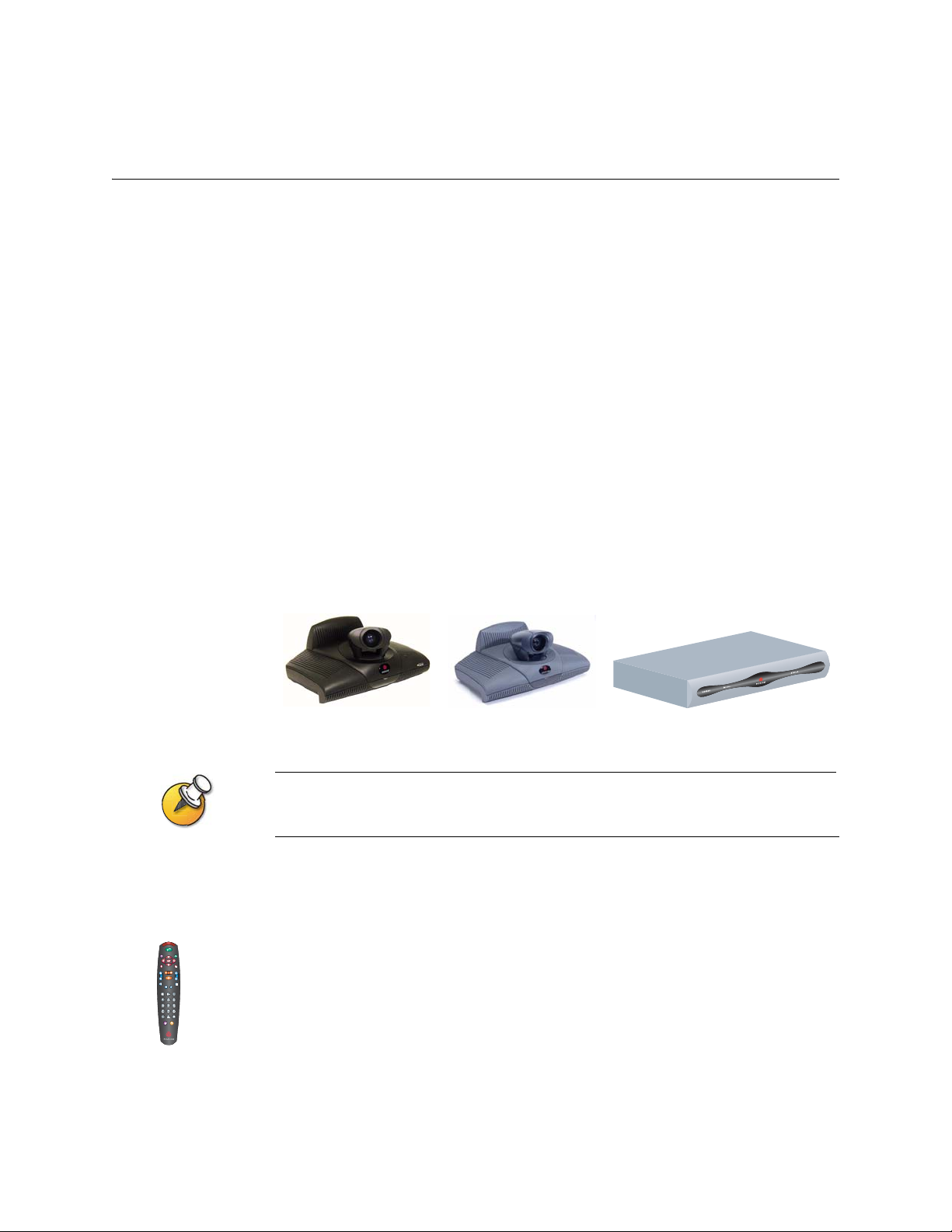
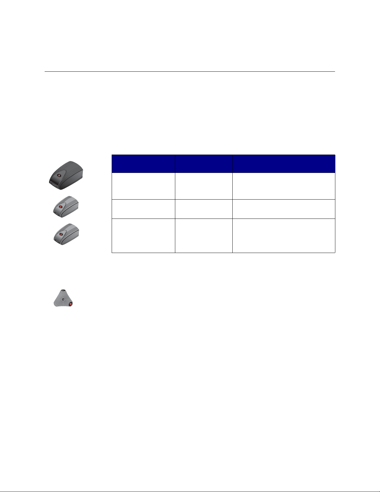
Main System
The ViewStation EX and ViewStation FX set-top systems provide cutting-edge
videoconferencing technology in a sleek design. The set-top contains the main
camera, system software, and internal hardware.
The VS4000 is a rack-mounted videoconferencing system that provides enhanced
videoconferencing capabilities including connections for up to three cameras and
a VCR or DVD, up to five monitors (four NTSC or PAL and one VGA), VCR inputs
and outputs, LAN connectivity for a computer, and connections for an external
audio system.
ViewStation EX
The original VS4000 uses 4-pin mini-DIN connectors for all S-Video connections; the
enhanced VS4000 uses dual BNC connectors.
ViewStation FX
VS4000
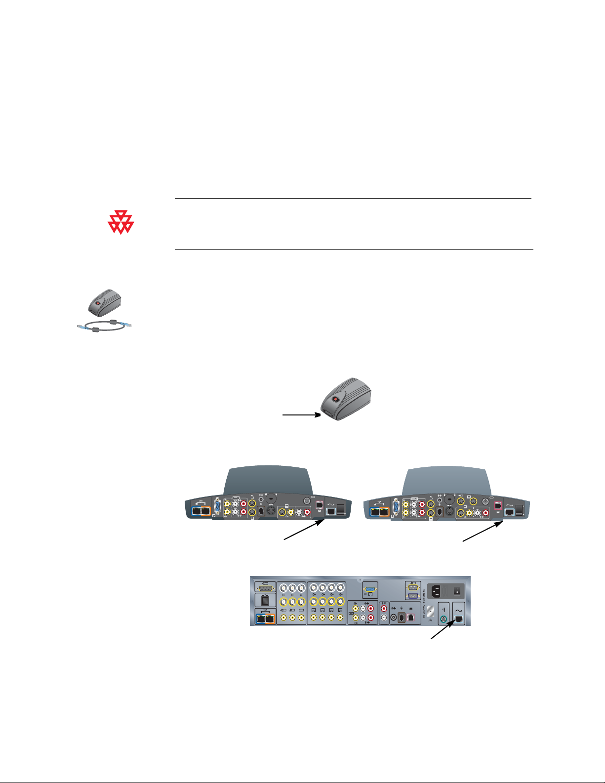
Remote Control
The remote control is designed to make it easy to set up and operate the system —
a clearly marked, color-coded button corresponds to each common user task.
For more information about how to use the remote control, refer to the Getting
Started Guide available in the Documentation Library on the CD that came with the
system or at the Polycom web site, www.polycom.com/videodocumentation.
1-6 www.polycom.com/videodocumentation
Page 15
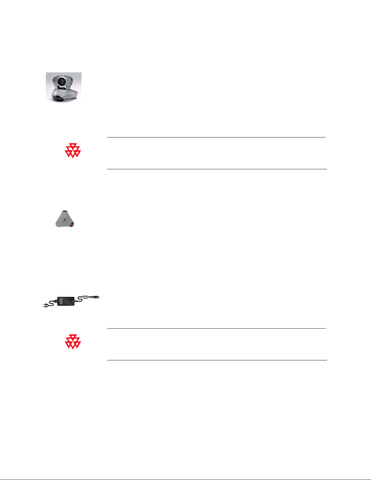
Main Camera
Chapter 1 - Introducing the ViewStation EX, ViewStation FX, and VS4000 Systems
Microphone
The ViewStation EX and ViewStation FX come with an integrated main camera.
Polycom recommends the Polycom PowerCam
™
as the main camera for the
VS4000 because the system uses a single connector for camera power and video,
camera control, and the camera’s integrated infrared remote control receiver.
The VS4000 system can also use a Sony EVI-D100 (NTSC) or EVI-D100P (PAL)
camera as its main camera.
The enhanced VS4000 is designed to be used with the PowerCam. Although it can use any
of the cameras supported by the original VS4000, the full Pan/Tilt/Zoom (PTZ) functionality
is available only with the PowerCam.
The microphone pod provides audio input to the system. Its advanced audio
technology focuses on the speaker so that the speaker’s voice does not have to
compete with background noises, such as the sound from an air conditioner, to be
heard. The microphone pod is designed to pick up voices from any direction.
The ViewStation EX comes standard with one microphone pod; the
ViewStation FX and VS4000 come with two.
Power Supply
The ViewStation EX and ViewStation FX set-top systems have an external power
supply; the VS4000 has an internal power supply. They all use line voltages
between 90V and 260V and line frequencies from 47 Hz to 63 Hz.
Do not use any power supply other than the one supplied with your ViewStation EX or
ViewStation FX system. Using the wrong power supply will void the warranty and may
damage your system.
© Polycom, Inc. 1-7
Page 16
Administrator’s Guide for ViewStation EX, ViewStation FX, and VS4000
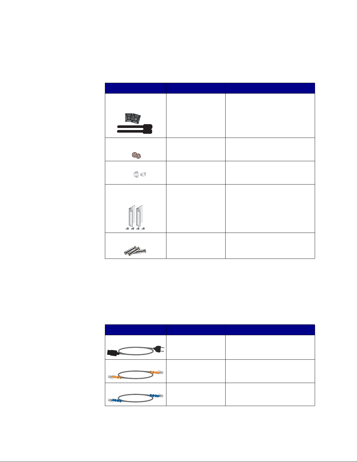
Hardware Kit
The hardware kit that comes with the system includes:
Item System Description
Cable ties and cable tie
mounts
Disks of hook-and-loop
material
Vinyl feet ViewStation EX
Rack-mount bracke ts
and screws
Batteries ViewStation EX (3)
ViewStation EX (2)
ViewStation FX (2)
VS4000 (4)
ViewStation EX
ViewStation FX
ViewStation FX
VS4000 For mounting the system in a rack
ViewStation FX (3)
VS4000 (6)
For keeping the system’s cables
from becoming entangled
For securing the ViewStation EX or
ViewStation FX set-top unit to the
top of a monitor
For stabilizing the set-top unit if the
top of your monitor slopes back
sharply
For the remote control
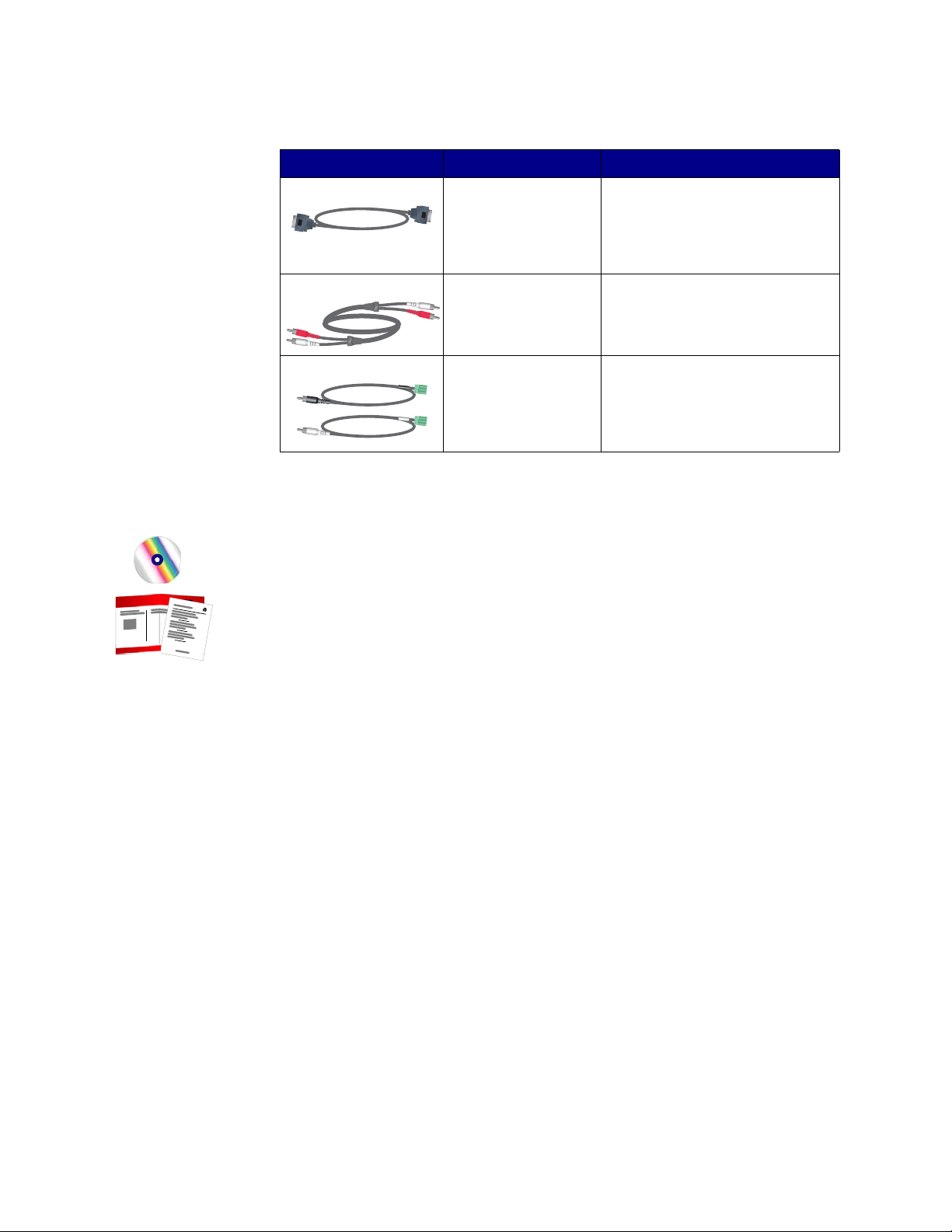
Cables
The following cables come with either the ViewStation EX, ViewStation FX, or
VS4000 system. For more information about which cables are standard and
optional with your particular system and how to connect them, refer to the system
setup card that was provided with your system.
Cable Name System Description
Power cord ViewStation EX,
ViewStation FX,
VS4000
LAN cable ViewStation EX,
ViewStation FX,
VS4000
PC LAN cable ViewStation FX,
VS4000
1-8 www.polycom.com/videodocumentation
Black cord that provides power to
the power supply or the system.
Cable with orange RJ-45
connectors that connects to the
LAN.
Cable with blue RJ-45 connectors
that connects to a PC.
Page 17
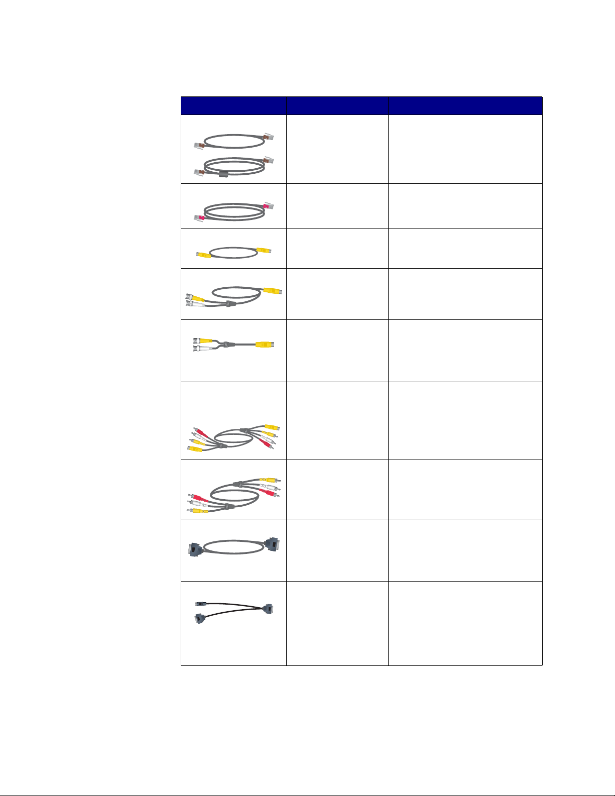
Chapter 1 - Introducing the ViewStation EX, ViewStation FX, and VS4000 Systems
Cable Name System Description
Microphone pod cables ViewStation EX,
ViewStation FX,
VS4000
Telephone cable ViewStation EX,
ViewStation FX,
VS4000
S-Video cables ViewStation EX,
ViewStation FX
Original VS4000
Cables with brown RJ-11
connectors that connect to
microphone pods.
Pink cable that connects to the
POTS line (in approved countries
only).
Cables with yellow 4-pin mini-DIN
connectors for connecting to
monitors and cameras.
S-Video cables Enhanced VS4000 Cables with yellow and white BNC
connectors and yellow 4-pin
mini-DIN connectors for connecting
to monitors and cameras.
S-Video adapters Enhanced VS4000 Short cables with yellow and white
BNC connectors and yellow 4-pin
mini-DIN connectors for connecting
standard S-video cables to the
system.
Combination S-Video,
audio, and composite
video cables
ViewStation EX,
ViewStation FX
Cables with yellow 4-pin mini-DIN
connectors and yellow, red, and
white RCA connectors for
connecting a monitor to provide
video and audio
VCR cables ViewStation FX,
VS4000
Cable with yellow, red, and white
RCA connectors that connect to a
VCR or DVD.
VGA cable ViewStation EX,
ViewStation FX,
VS4000
Cable with black (for
ViewStation EX and FX) or yellow
(for VS4000) DB-15 connectors that
connects to an additional monitor or
projector.
VGA adapter ViewStation FX Short cable with a single black
high-density subminiature D
connector at one end, and standard
VGA and S-Video connectors at the
other end to connect to the cables
for an S-Video monitor or a VGA
monitor or projector.
© Polycom, Inc. 1-9
Page 18
Administrator’s Guide for ViewStation EX, ViewStation FX, and VS4000
Cable Name System Description
Serial port cable VS4000 Cable with black (for
Audio cable VS4000 Cable with red and white RCA
Mixer cables Enhanced VS4000 Cables with mini-Phoenix
Documentation
ViewStation EX and FX) or purple
(for VS4000) DB-9 connectors that
connects to a touch panel or other
RS-232 device.
connectors for connecting to the
main monitor’s audio inputs or to an
external audio system.
connectors that connect to a
Polycom audio mixer. One cable
has a white RCA connector; the
other has a black one.
In addition to the documentation CD, you received the following hardcopy
documents with your system:
❑ Read Me First, which lists where to get the Release Notes, video-test call
numbers, and product support information.
❑ Setting up the System, which describes how to install the system.
You can find the latest documentation at the Polycom web site,
www.polycom.com/videodocumentation.
1-10 www.polycom.com/videodocumentation
Page 19
Chapter 1 - Introducing the ViewStation EX, ViewStation FX, and VS4000 Systems
Optional System Components
This section describes the components that you can purchase as an option with a
ViewStation EX, ViewStation FX, or VS4000 system.
Network Interface Modules
These network interface modules are available for the ViewStation EX,
ViewStation FX, or VS4000 system:
Network Interface
Module
System Description
Quad BRI ViewStation EX,
PRI
V.35/RS-449/RS-530 ViewStation EX,
Additional Microphone Pod
You can connect up to two microphone pods to the system or to a Visual
Concert FX unit.
If you install more than one microphone pod, ensure that all microphone pods are
at least 6 ft (1.8 m) apart.
ViewStation FX,
VS4000
ViewStation FX,
VS4000
ViewStation FX,
VS4000
Allows you to connect to an ISDN
network using up to four BRI lines.
Allows you to connect to an ISDN
network using a PRI line.
Allows you to connect to third-party
network equipment, including
encryption equipment and RS-366
dialers.
© Polycom, Inc. 1-11
Page 20

Administrator’s Guide for ViewStation EX, ViewStation FX, and VS4000
Visual Concert FX
The Visual Concert FX lets you share content from your computer during calls and,
if you need to make a presentation, it also lets you connect a projector or a VGA
monitor. You can use the Visual Concert FX with the ViewStation EX,
ViewStation FX, and VS4000 system.
The Visual Concert FX has dual stream capability, so you can display video and
graphics at both the near and far sites, with video on one monitor and the live
graphics on a second monitor. The Visual Concert FX provides VGA output at a
screen resolution of up to 1280 x 1024 pixels.
For more information about the Visual Concert FX, refer to the documentation that
came with your Visual Concert FX. You can obtain copies of the Visual Concert FX
documents at the Polycom web site, www.polycom.com/videodocumentation.
Document Camera or Other Additional Camera
Besides the main camera for your system, you can connect other cameras. You can
connect a document camera as well as an additional pan/tilt/zoom (PTZ) camera
to the ViewStation FX or VS4000; you can connect only a stationary second camera
to the ViewStation EX.
You can use any of the following PTZ cameras as an additional camera on a
ViewStation FX or VS4000 system:
❑ Sony
®
EVI-D30 (NTSC) or Sony EVI-D31 (PAL)
❑ Sony EVI-D70 (NTSC) or Sony EVI-D70P (PAL)
❑ Sony EVI-D100 (NTSC) or Sony EVI-D100P (PAL)
❑ Elmo PTC-100S (NTSC)
❑ Elmo PTC-110R (PAL)
1-12 www.polycom.com/videodocumentation
Page 21
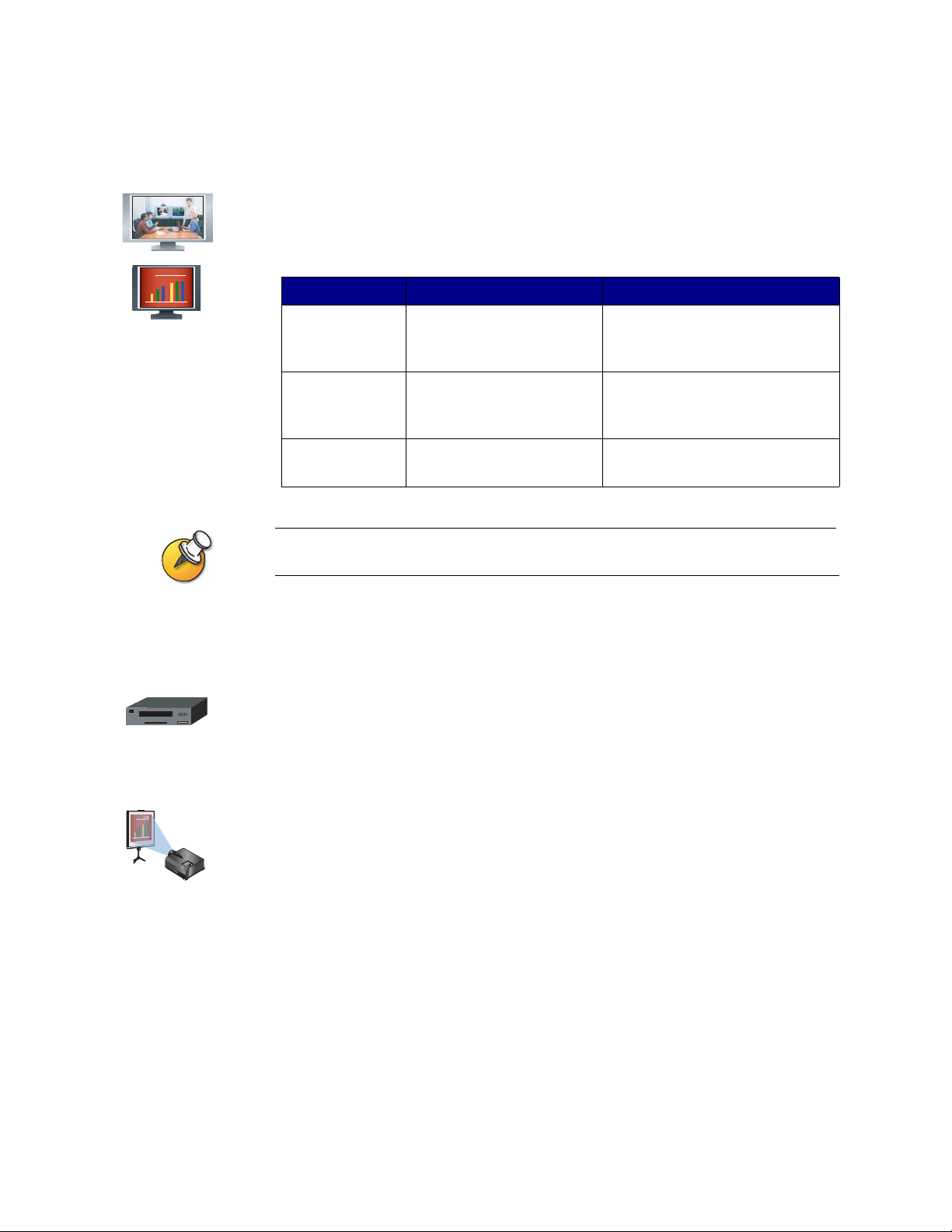
Additional Monitor
You can get more flexibility in how you view calls by connecting an additional
monitor, such as a VGA monitor, to your system. For example, an additional
monitor allows you to view the person you call at the same time as you view a
presentation.
System Number of Monitors Type of Monitors
Chapter 1 - Introducing the ViewStation EX, ViewStation FX, and VS4000 Systems
VCR
VCR/DVD
ViewStation EX Up to two television monitors
and a VGA monitor
ViewStation FX Up to four television monitors
and a VGA monitor
VS4000
For high-resolution presentations, Polycom recommends using a VGA (computer) monitor.
Up to four tele vision monitors
and a VGA monitor
Primary monitor can be S-video or
composite. The second television
monitor must be S-video.
Primary monitor can be S-video or
composite. Other three television
monitors must be S-video.
All four television monitors can be
S-video or composite.
You can connect a VCR or DVD to play recorded material during a call or to record
your videoconference. You can also connect two VCRs to play material and record
the conference at the same time.
Projector
You can connect a projector to your Polycom system. This can be very useful
during presentations in large rooms.
© Polycom, Inc. 1-13
Page 22

Administrator’s Guide for ViewStation EX, ViewStation FX, and VS4000
Other Optional Components
You can add several other optional components to your system, such as those
listed below. For more information, see your Polycom distributor.
❑ Touch panel — Allows you to operate the system with a touch panel rather
than the remote control.
❑ VS4000 only: External infrared (IR) sensor — Allows you to install the system
out of sight and use a camera that does not include a built-in IR sensor.
❑ Audio mixer — Lets you enhance the sound quality for calls in large rooms.
Polycom recommends using the Polycom Vortex line of products for installed audio.
1-14 www.polycom.com/videodocumentation
Page 23

2
Setting Up Your System Hardware
This chapter describes how to set up your system with the required components
and optional equipment. It also includes checklists to help you prepare the site,
including network connectivity, required network hardware, and room
assessment.
If you need additional installation information, refer to the system setup document
that was provided with your system.
For optional components, you can also refer to the setup sheet that was shipped
with the component.
To obtain additional copies of any of these documents, refer to the documentation
CD that came with the system or go to the Polycom web site,
www.polycom.com/videodocumentation.
What’s in this chapter? Page
Standard System Set-up 2-2
Optional Equipment Set-up 2-10
© Polycom, Inc. 2-1
Page 24
Administrator’s Guide for ViewStation EX, ViewStation FX, and VS4000
Standard System Set-up
This section describes how to connect the components that are required for the
basic system set-up. Procedures for connecting additional equipment are in the
next section, Optional Equipment Set-up on page 2-10.
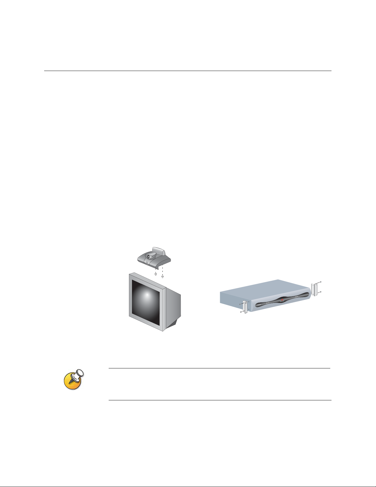
Positioning the Main System
The ViewStation EX and ViewStation FX systems are designed to be placed on top
of a monitor. If the monitor’s chassis slopes back sharply, you may need to install
feet on the bottom of the system to stabilize it. The hardware kit you received with
the unit includes a pair of self-adhesive feet.
The VS4000 system is designed as a tabletop or rack-mounted unit. To mount it in
an equipment rack, you will need to attach the mounting brackets provided with
the system.
To position the system:
1. If necessary, install feet (ViewStation EX or ViewStation FX) or mounting
brackets (VS4000) on the system.
2. Place the system in the desired location. Leave enough space to work, so that
you can connect the cables easily.
The original VS4000 uses 4-pin mini-DIN connectors for all S-Video connections; the
enhanced VS4000 uses dual BNC connectors. Because of this, installation procedures for
cameras and monitors are slightly different for the two.
2-2 www.polycom.com/videodocumentation
Page 25
Main Camera
Chapter 2 - Setting Up Your System Hardware
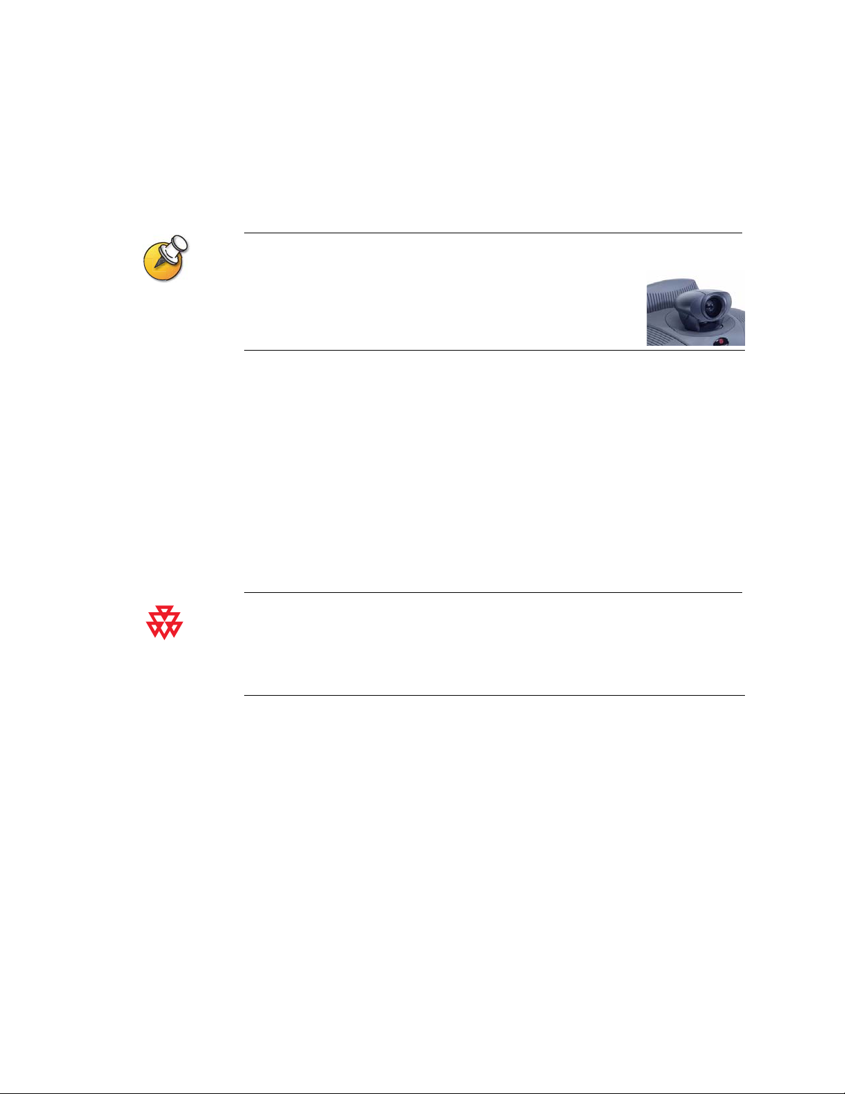
The ViewStation EX and ViewStation FX come with an integrated main camera,
which is designed with a wide-angle lens.
Some older models of the ViewStation EX and ViewStation FX use a
detachable wide-angle conversion lens. The detachable wide-angle lens
cannot be used on systems with the newer style of camera.
Do not install a wide-angle conversion lens if your system uses the type
of camera shown here.
The VS4000 uses a separate camera, which allows you to install the system in an
equipment room rather than the conference room. This section describes how to
install a Polycom PowerCam
™
or other camera as the main camera.
The camera you connect to the Camera 1 input determines whether your system is
an NTSC or PAL system. The VS4000 detects the camera type and provides the
appropriate video to the TV monitor. Because of this, you must connect a camera
to the Camera 1 input.
For best results, position cameras so that they do not normally point directly at a
window or other source of bright light.
The enhanced VS4000 system’s Camera 1 connections provide full PTZ functionality for the
Polycom PowerCam only.
The original VS4000 system’s Camera 1 connections provide this functionality for all
supported PTZ cameras.
© Polycom, Inc. 2-3
Page 26
Administrator’s Guide for ViewStation EX, ViewStation FX, and VS4000
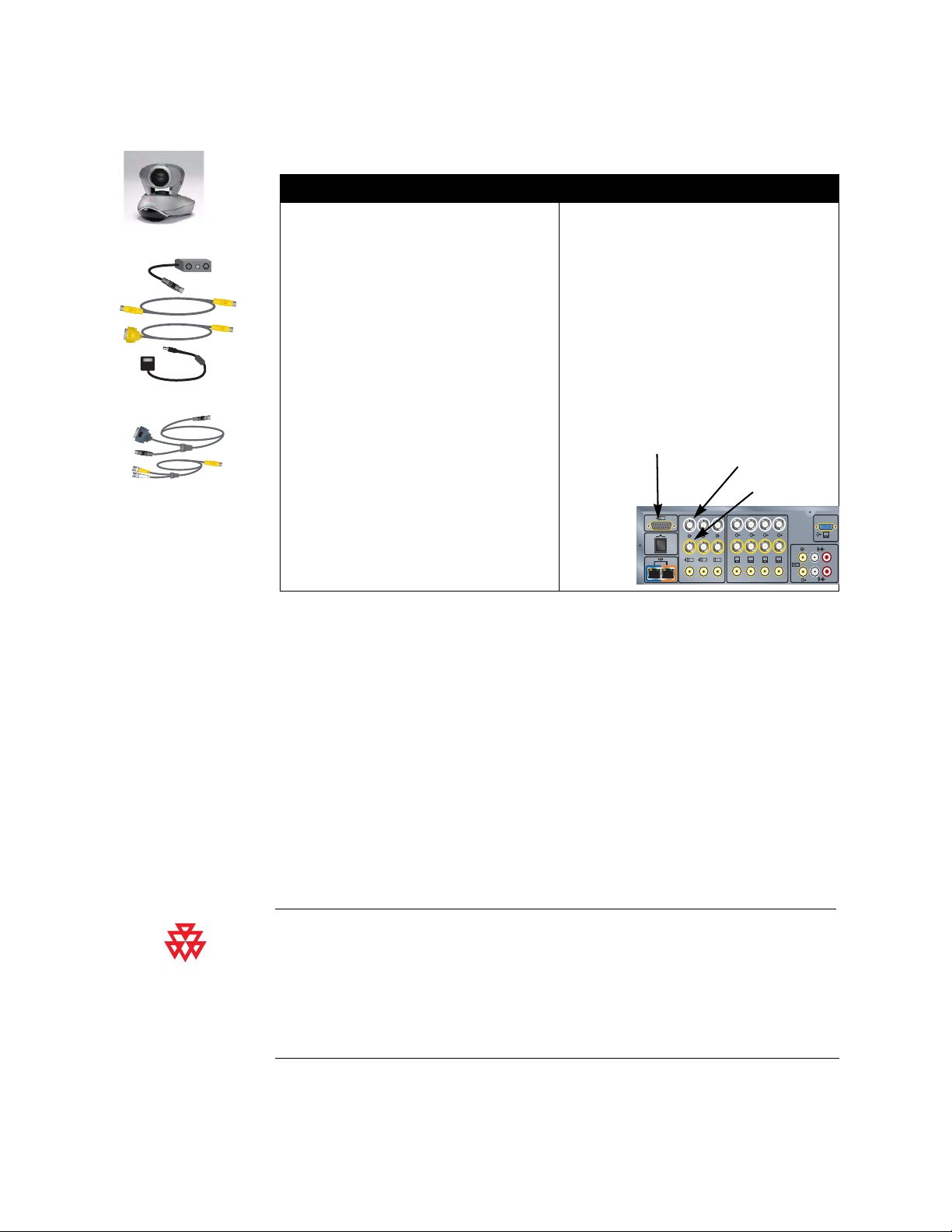
To connect a Polycom PowerCam to the VS4000:
Original VS4000: Enhanced VS4000:
Original VS4000
Enhanced VS4000
1. Connect the break-out cable to the
PowerCam.
2. Connect the S-video cable to the
system’s Camera 1 S-Video connector
and to the 4-pin mini-DIN connector on
the right side of the break-out cable’s
connector block.
3. Connect the VISCA cable to the
system’s DB-9 camera control
connector and to the 8-pin mini-DIN
connector on the break-out cable.
4. Be sure the camera’s power is switched
off.
1. Connect the single end of the video and
control cable to the PowerCam.
2. Connect the S-video cable connector to
an S-video to BNC adapter, and connect
the adapter’s yellow BNC connector to
the camera 1 C connector, and the white
connector to the camera 1 Y connector
on the VS4000 system’s rear panel.
3. Connect the camera cable’s yellow
DB-15 connector to the camera control 1
connector on the rear panel of the
system.
Camera Control
5. Connect the camera’ s powe r pack to the
center connector on the break-out
cable’s connector block, and to the
appropriate power cord.
6. Connect the power cord to a power
outlet.
1
Y
C
Y
C
4
1
2
To connect other types of main camera to the original VS4000:
Camera 1 Y
Camera 1 C
4321
3
XVGA
5
1. Connect an S-video cable to the camera’s S-video connector and the Camera 1
connector on the system.
2. Connect a camera control cable (8-pin mini-DIN to DB-9) to the camera’s
VISCA in connector and to the camera control 1 connector on the rear panel of
the system.
3. Connect the camera’s power pack or cord to a power outlet.
If you want to connect an additional camera to your system, such as a document
camera, see the Document Camera or Other Additional Camera section on page
2-18.
If you install an original VS4000 system out of the range of the remote control (for example,
in a separate equipment room), you will need to connect an external infrared (IR) sensor and
place it in the conference room. To order an external IR sensor, contact your Polycom
reseller.
The enhanced VS4000 system uses the IR sensor built into the Polycom PowerCam, and
does not require an external IR sensor.
2-4 www.polycom.com/videodocumentation
Page 27
Main Monitor
Chapter 2 - Setting Up Your System Hardware
You will need to connect a television monitor to the system. This may be an NTSC
or PAL monitor, depending on your system.
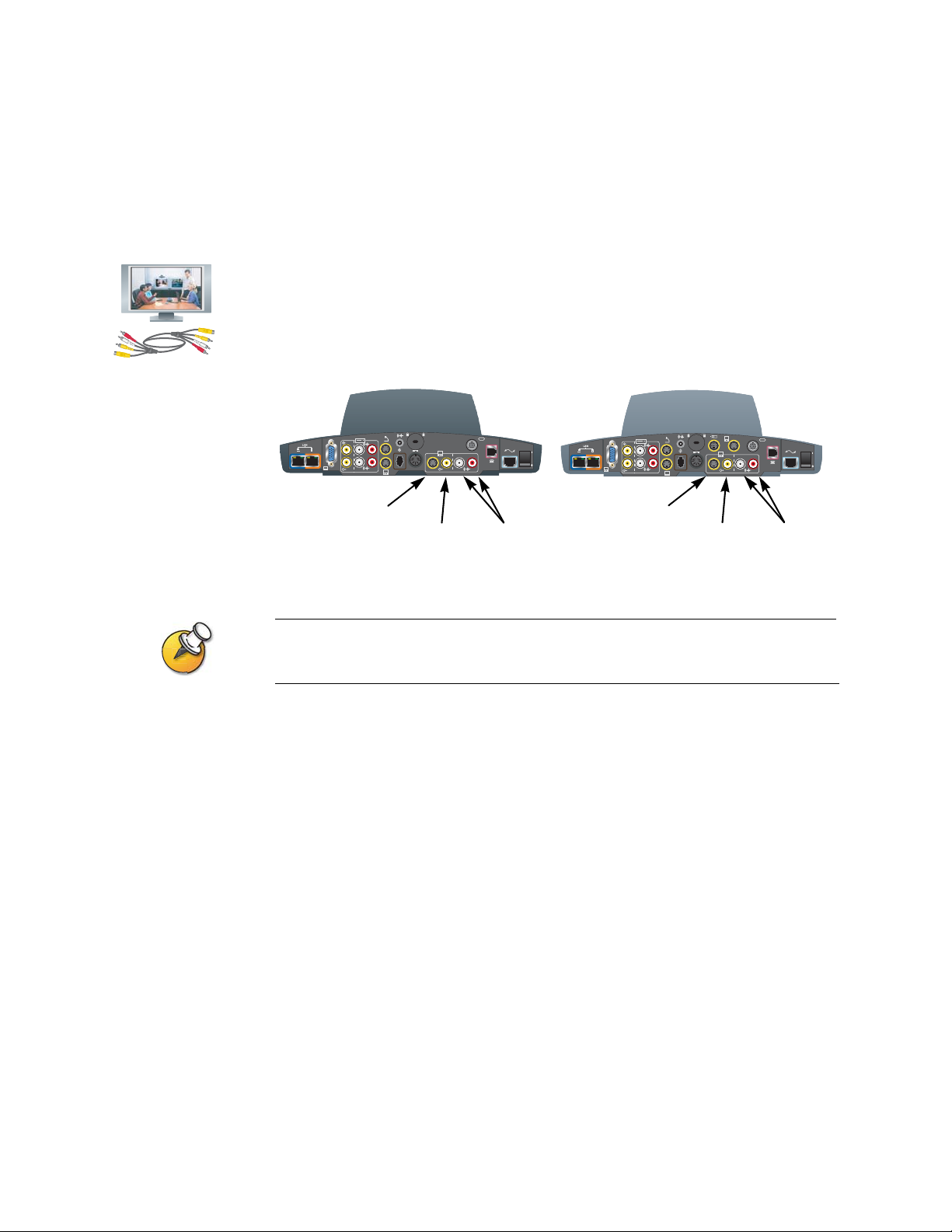
To connect a monitor to a ViewStation EX or ViewStation FX system:
>> Connect the monitor to the system’s Monitor 1 S-Video or composite video
output, and to the Monitor 1 audio outputs.
ViewStation EX
XVGA
4
Monitor 1
S-Video
2
3.3V
7A
12V 3A
2
Monitor 1
Composite
0101
1
Audio
Outputs
ViewStation FX
XVGA
4
Monitor 1
S-Video
2
3.3V
7A
12V 3A
2
Monitor 1
Composite
4
3
0101
1
Audio
Outputs
S-Video provides superior video quality, and is strongly recommended if the system is to be
configured to display Asian fonts.
© Polycom, Inc. 2-5
Page 28
Administrator’s Guide for ViewStation EX, ViewStation FX, and VS4000
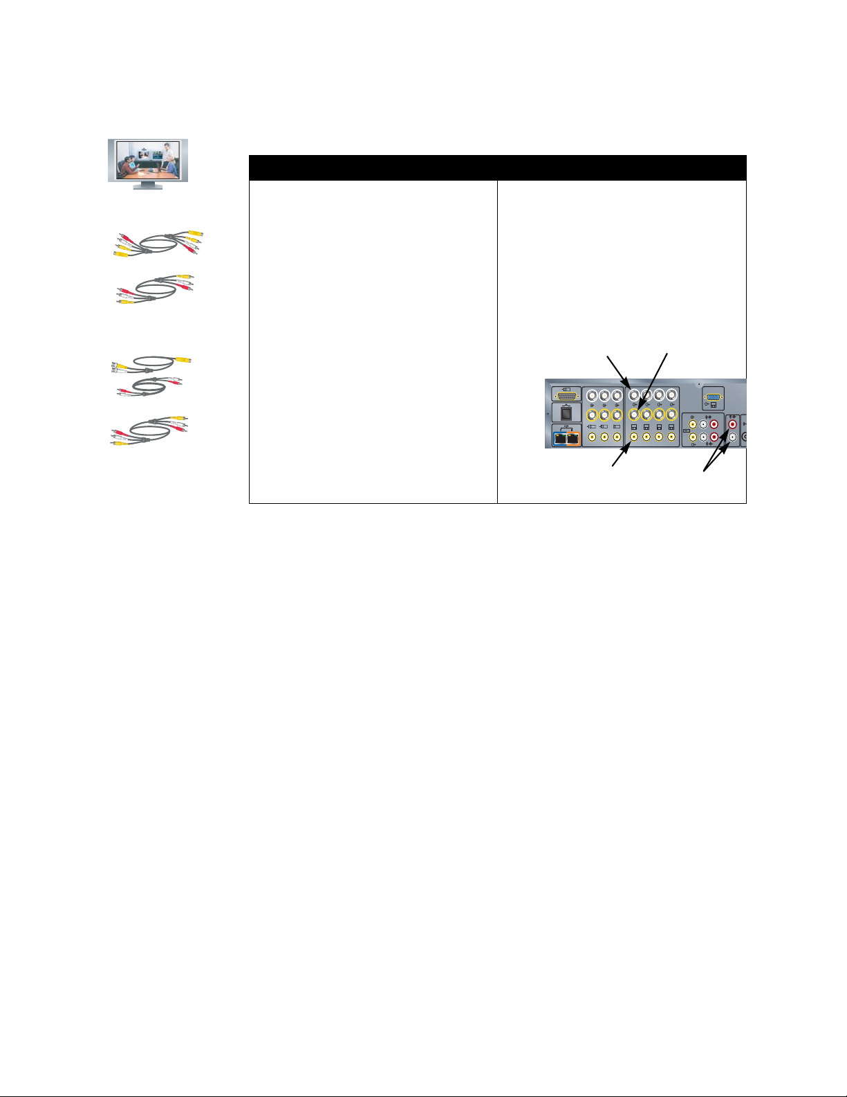
To connect a monitor to a VS4000 system:
Original VS4000: Enhanced VS4000:
Original VS4000
or
Enhanced VS4000
or
1. Connect the S-video/audio/composite
video cable to the system’s Monitor 1
S-Video or composite video connector
and to the monitor’s video input.
2. Use the audio cable or the red and white
connectors on the
S-video/audio/composite video cable to
connect the monitor’s audio inputs to the
system’s audio outputs.
1. Connect the S-video cable to the
monitor’s S-video input and to the
system’s Monitor 1 Y (white) and C
(yellow) connectors.
2. Use the audio cable or the red and white
connectors on the
S-video/audio/composite video cable to
connect the monitor’s audio inputs to the
system’s audio outputs.
Monitor 1 Y
1
Y
C
1
Monitor 1
Composite
Y
C
4
2
Monitor 1 C
XVGA
4321
3
Audio
Outputs
5
2-6 www.polycom.com/videodocumentation
Page 29
Microphone
Chapter 2 - Setting Up Your System Hardware
For best audio, place the microphone pod:
❑ on a flat surface (table, wall, or ceiling) away from obstructions, so the sound
will be directed into the microphone elements properly,
❑ at least 3 ft (0.9 m) from the system, to prevent audio feedback
❑ centered in the area where call participants will be.
If you have two microphone cables, use the longer one to connect the microphone to the
system. If you connect an additional microphone, use the shorter cable to connect it to the
first one. The cable between microphones must not be longer than the cable from the system
to the first microphone.
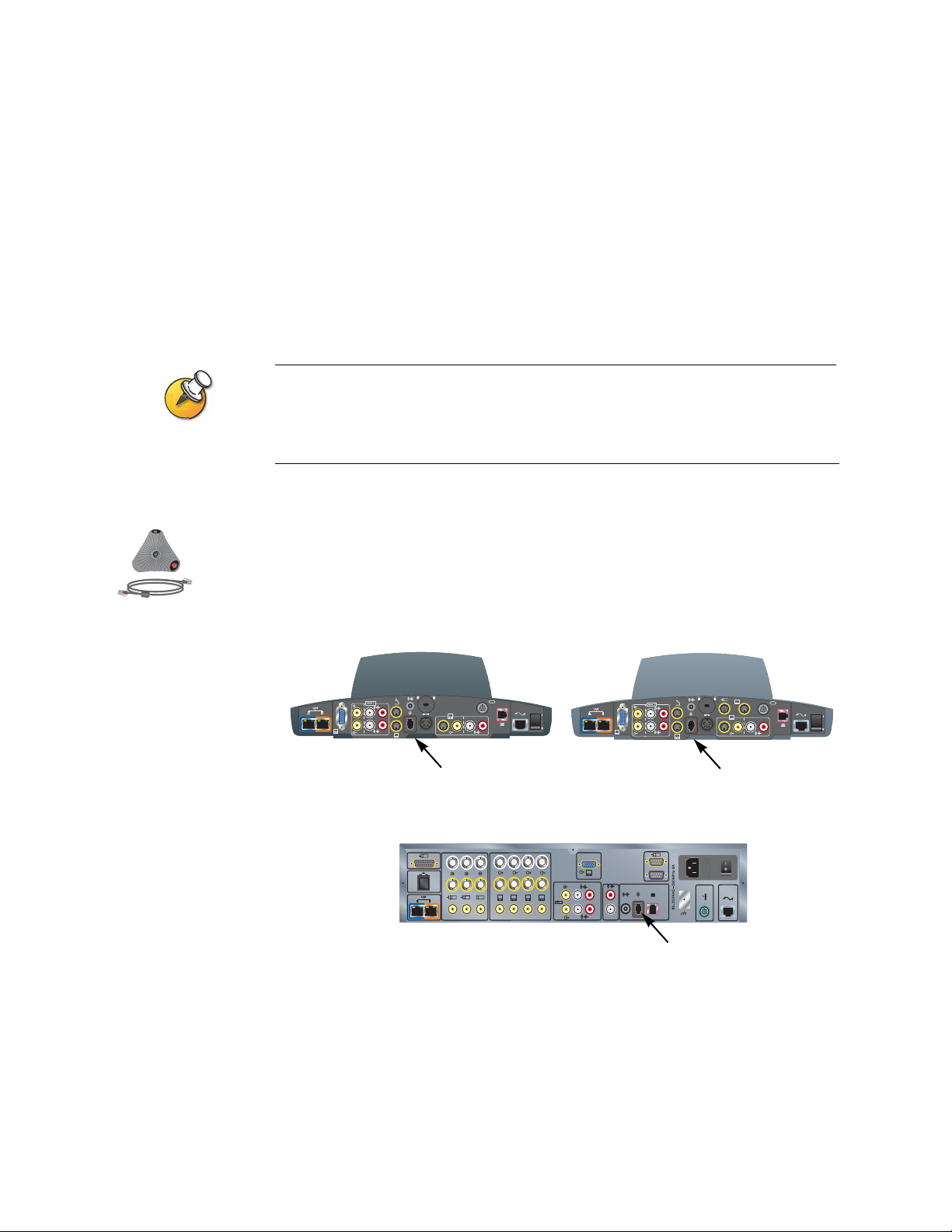
To connect a microphone pod:
>> Connect the microphone pod to the system’s microphone connector using the
brown RJ-9 microphone cable. Ensure that the ferrite bead is on the end that
connects to the system.
ViewStation EX
XVGA
4
2
3.3V
7A
12V 3A
2
0101
1
Microphone
VS4000
1
Y
C
Y
C
4
1
2
XVGA
5
4321
3
ViewStation FX
XVGA
4
4
0101
4
2
2
3
3.3V
7A
12V 3A
1
Microphone
Microphone
0101
© Polycom, Inc. 2-7
Page 30
Administrator’s Guide for ViewStation EX, ViewStation FX, and VS4000
Power Supply
The ViewStation EX and ViewStation FX set-top systems have an external power
supply.
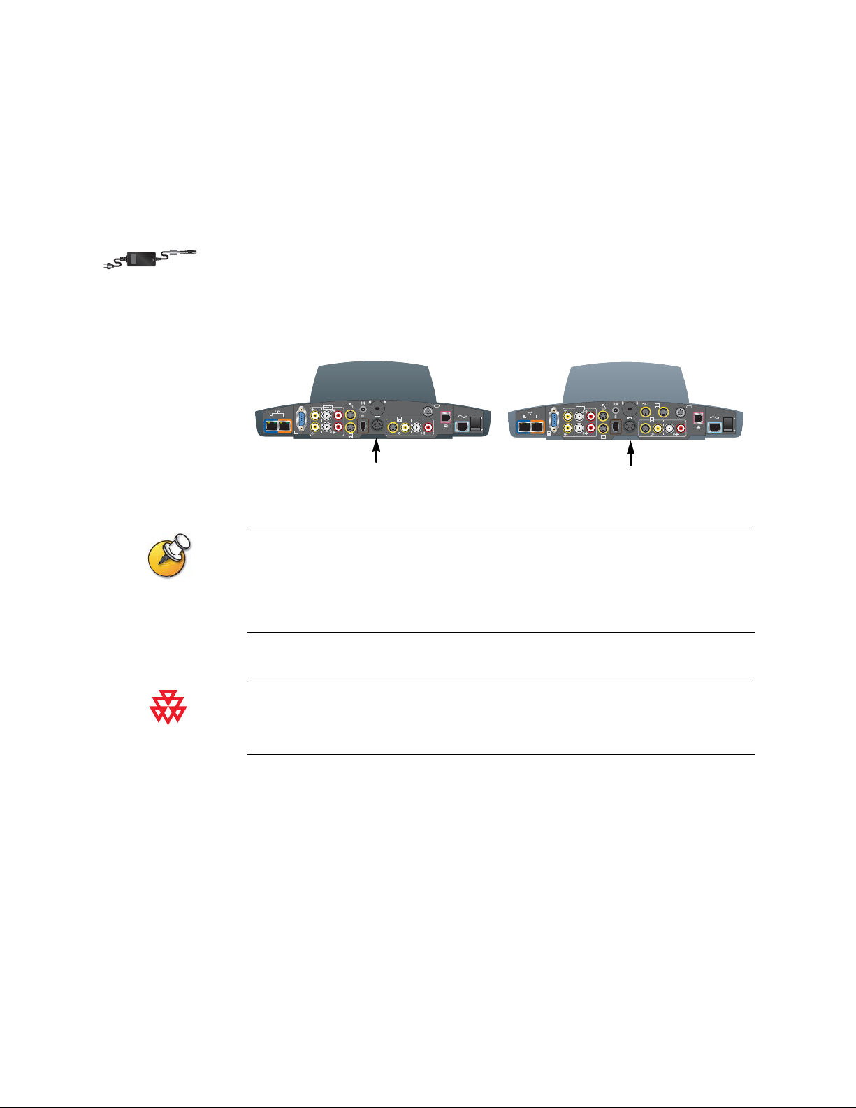
To connect the power supply
1. Connect the power supply to the power connector on the back of the system.
2. Connect the power cord to the power supply.
ViewStation EX
XVGA
4
2
3.3V
12V 3A
2
Power
7A
0101
1
ViewStation FX
XVGA
4
2
3.3V
2
Power
12V 3A
4
3
7A
0101
1
Leave the power cord unplugged until you have connected all standard and optional
equipment to the system.
Be sure to remove the packaging collar from around the ViewSt ation EX or ViewStation FX
system’s camera before powering on the system.
Do not use any power supply other than the one supplied with your ViewStation EX or
ViewStation FX system. Using the wrong power supply will void the warranty and may
damage your system.
2-8 www.polycom.com/videodocumentation
Page 31

Remote Control
Chapter 2 - Setting Up Your System Hardware
The remote control uses three AAA batteries, which are included in the hardware
kit.
To install batteries in the remote control:
1. Remove the battery cover from the back of the remote control.
2. Refer to the diagram inside the remote control, and install the batteries in the
orientation shown.
3. Reinstall the battery cover on the remote control.
© Polycom, Inc. 2-9
Page 32
Administrator’s Guide for ViewStation EX, ViewStation FX, and VS4000
Optional Equipment Set-up
This section describes how to connect optional components to theViewStation EX,
ViewStation FX, or VS4000 system.
Network Interface Modules
This section gives procedures for installing the following network interface
modules:
❑ Quad BRI — Allows you to connect to an ISDN network using up to four BRI
lines.
❑ PRI — A llow s you to co nnec t to a n ISD N network using a PRI line. This option
is available for the ViewStation FX and VS4000.
❑ V.35/RS-449/RS-530 — Allows you to connect to third-party network
equipment, including encryption equipment and RS-366 dialers.
ViewStation EX,
ViewStation FX,
or VS4000
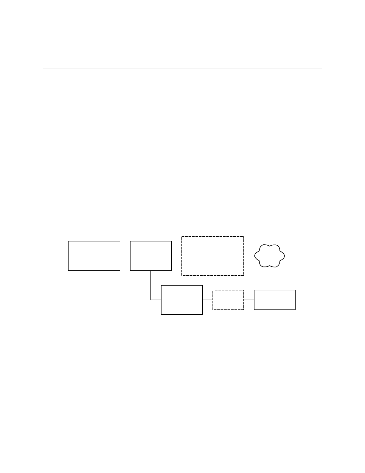
The diagram below shows a general view of how network interface modules are
installed.
Network
interface
module
power supply
(if using PRI)
Additional device such as
NT-1 if using Quad BRI,
CSU if using PRI,
encryption equipment if
using V.35/RS-449/RS-530
External
UPS
ISDN
network
Power source
2-10 www.polycom.com/videodocumentation
Page 33

ISDN Network Hardware Checklist
Depending on your network type, you will need the following hardware:
If your ISDN network is... You will need...
BRI • Quad BRI network interface module with cables
Chapter 2 - Setting Up Your System Hardware
• Up to 4 BRI lines that will not be shared with other
equipment
• NT-1 device, if the system will be connected to a PBX
network that does not provide an S/T interface
Note: If your Quad BRI system is connected to a PBX
that provides an S/T interface, do not use an NT-1 device.
PRI/T1
(commonly available in
North America)
PRI/E1
(commonly available
outside North America)
Serial
(V.35/RS-449/ RS-530)
Quad BRI Network Interface Module
The Quad BRI network interface module allows you to make ISDN calls using up
to four BRI lines.
In addition to the Quad BRI network interface module and the cables provided
with it, you will need an NT-1 device if your site does not use an internal telephone
system (PBX). A PBX or an NT-1 device provides the S/T interface that the Quad
BRI module requires.
• PRI network interface module with cable
• North America: Channel Service Unit (CSU), if the
system will not be connected to a PBX network
• PRI line
• PRI network interface module with cable
• PRI line
• Serial V.35/RS-449/RS-530 network interface module
• Third-party network equipment and cables
© Polycom, Inc. 2-11
Page 34
Administrator’s Guide for ViewStation EX, ViewStation FX, and VS4000
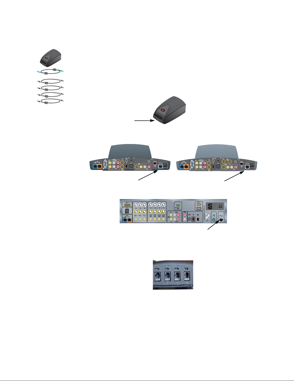
To install a Quad BRI network interface module:
1. Make sure your system is powered off.
2. Connect the system side of the Quad BRI network interface module to the
system using the network interface cable that is color-coded light blue on one
end, green on the other.
System
side
Quad BRI
ViewStation EX
2
3.3V
XVGA
4
12V 3A
2
Network interface
7A
0101
1
Network interface
ViewStation FX
XVGA
4
4
3
2
3.3V
7A
12V 3A
2
0101
1
VS4000
1
Y
C
Y
C
4
1
2
XVGA
5
4321
3
4
0101
Network interface
3. Connect the network side of the Quad BRI network interface module to the
NT-1 device or to the ISDN network, as appropriate. If you do not connect BRI
lines to all four ports, connect the ports in ascending order.
4. If you are using an NT-1 device, connect it to the ISDN network.
2-12 www.polycom.com/videodocumentation
Page 35

PRI Network Interface Module
The PRI network interface module allows you to make ISDN calls using a PRI line.
You may need one of these items in addition to the PRI network interface module
and the items provided with it:
❑ External Channel Service Unit (CSU) — If you connect a PRI T1 network
interface module outside a PBX, you may wish to connect it through a CSU.
The CSU isolates the PRI from the network, and continues to transmit a signal
to the network even if the PRI network interface module loses power or is
disconnected. This prevents the line from being deactivated. CSUs are used
only in North America.
❑ PBX crossover cable — An RJ-45 crossover cable may be required when
connecting the PRI network interface module to a PBX or other third-party
network access device.
❑ 75 Ω coaxial adapter — The PRI E1 line termination is 120 Ω. In some areas,
however, the E1 network connection is via a 75 Ω coaxial cable. The PRI
network interface module does not directly support this, but you can obtain
passive adapter devices from various vendors.
Chapter 2 - Setting Up Your System Hardware
© Polycom, Inc. 2-13
Page 36

Administrator’s Guide for ViewStation EX, ViewStation FX, and VS4000
To install the PRI network interface module:
1. Ensure that the system is powered off.
2. Connect peripheral side of the PRI network interface module to the system
using the network interface cable that is color-coded light blue on both ends.
System
side
PRI
ViewStation EX
2
3.3V
XVGA
4
12V 3A
2
Network interface
7A
0101
1
Network interface
ViewStation FX
XVGA
4
4
3
2
3.3V
7A
12V 3A
2
0101
1
VS4000
1
Y
C
Y
C
4
1
2
XVGA
5
4321
3
4
0101
Network interface
3. Connect the 12-volt DC power supply to the PRI network interface module
and then to the UPS or wall outlet.
The external 12-volt DC power supply is mandatory in European countries, and strongly
recommended in all installations.
If the PRI network interface module loses power, this creates an alarm condition that
may result in the service provider disabling the line. The external power keeps the PRI
network interface module from losing power when the system is powered off. Connect
the external power supply to an uninterruptable power supply (UPS) if possible.
4. Connect the PRI network interface module to the ISDN network or to the CSU
(North America only).
2-14 www.polycom.com/videodocumentation
Page 37
V.35/RS-449/RS-530 Network Interface Module
The V.35/RS-449/RS-530 network interface module allows you to connect the
system to third-party communication equipment such as encryption devices.
You will need to provide appropriate cables to connect the V.35/RS-449/RS-530
network interface module to your communication equipment.
Polycom only provides technical support for V.35, RS-449, and RS-530 cables built and
certified by Polycom. These cables are sold separately from the network interface module
and are available from P olycom.
To install a V.35/RS-449/RS-530 network interface module:
1. Ensure that the system is powered off.
2. Connect the peripheral side of the network interface module to the system
using the network interface cable that is color-coded light blue on both ends.
Chapter 2 - Setting Up Your System Hardware
System
side
ViewStation EX
2
3.3V
XVGA
4
12V 3A
2
Network interface
1
V.35/RS-449/RS-530
ViewStation FX
4
7A
0101
1
XVGA
4
2
2
3
3.3V
7A
12V 3A
0101
1
Network interface
VS4000
Y
C
Y
C
4
1
2
XVGA
5
4321
3
4
0101
Network interface
3. Connect the network side of the network interface module to the data
communications equipment.
© Polycom, Inc. 2-15
Page 38

Administrator’s Guide for ViewStation EX, ViewStation FX, and VS4000
• If you have only one cable, connect it to port 1 of the network interface
module and to the lowest-numbered port of the data communications
equipment.
• If the data communications equipment does not use dialing, do not
connect the cable connector marked RS366 Interface.
Additional Microphone Pod
You can connect an additional microphone pod to the system.
To connect an additional microphone pod:
1. Use the brown RJ-9 microphone cable to connect the additional microphone
pod to the available connector on the microphone pod already installed.
2. Place the microphone pods at least 6 ft (1.8 m) apart.
For more information about how to connect microphone pods, refer to the setup
sheet that came with your system.
Visual Concert FX
The Visual Concert FX uses the same connector on the system’s back panel as the
microphone pod. If you install aVisual Concert FX, you must use the connectors it
provides for the microphone pod or pods.
For more information about connecting the Visual Concert FX, refer to the Visual
Concert FX QuickStart card that came with your Visual Concert FX.
2-16 www.polycom.com/videodocumentation
Page 39

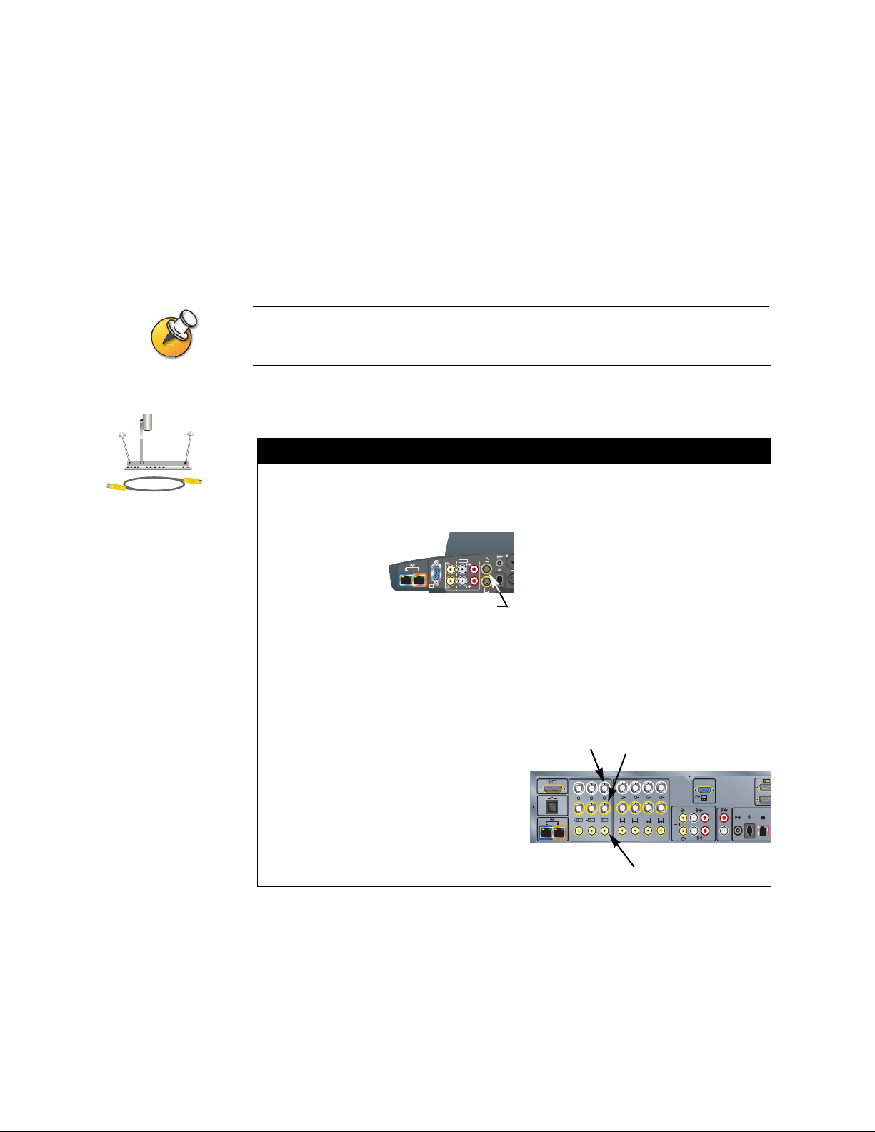
Chapter 2 - Setting Up Your System Hardware
To connect a Visual Concert FX:
1. Make sure the system is powered off.
2. Referring to the Visual Concert FX QuickStart, connect the single end of the
system cable to the system connector on the Visual Concert FX.
3. Connect the system cable’s LAN connector to the system’s blue LAN port,
which is at the left end of the back panel.
4. Connect the system cable’s microphone connector to the system’s microphone
cable connector.
Visual Concert FX
System
LAN
ViewStation EX
XVGA
4
2
3.3V
12V 3A
2
7A
0101
1
Microphone
LAN
ViewStation FX
XVGA
4
2
3.3V
12V 3A
2
4
3
7A
0101
1
Microphone
VS4000
4
0101
Microphone
LAN
1
Y
C
Y
C
4
1
2
XVGA
5
4321
3
5. Connect the microphone pod or pods to the Visual Concert FX using the
microphone pod cables included in the Visual Concert FX shipping box.
6. Connect the system cable’s power connector to the power supply.
7. Connect the power cord from the power supply to a power outlet.
You can connect a VGA monitor to the VGA output on the Visual Concert FX
instead of connecting the monitor directly to the rear panel of the system.
© Polycom, Inc. 2-17
Page 40
Administrator’s Guide for ViewStation EX, ViewStation FX, and VS4000
Document Camera or Other Additional Camera
Besides the main camera for your system, you can connect a document camera as
well as an additional pan/tilt/zoom (PTZ) camera to the ViewStation FX or
VS4000; you can connect only a stationary second camera to the ViewStation EX.
The enhanced VS4000 allows you to designate any camera input as the primary
camera.
Ensure that the system is powered off before you connect cameras. If you connect a PTZ
camera while the system is powered on, the system may not be able to control the camera.
To connect a document camera:
To a ViewStation EX or ViewStation FX: To a VS4000 system:
Connect an S-video cable to the document
camera and to the camera 2 connector on
the rear panel of the system.
2
XVGA
4
2
Camera 2
Original VS4000:
Connect an S-video cable to the document
camera and to the camera 2 connector on
the rear panel of the system.
Enhanced VS4000:
3.3V
12V
1. Connect one end of the yellow S-video
cable to the document camera.
2. Connect the other end of the S-video
cable to an S-video to BNC adapter.
3. Connect the adapter’s yellow BNC
connector to the camera 2 C connector,
and the white connector to the camera 2
Y connector on the VS4000 system’s
rear panel.
Camera 2 Y
1
Y
C
1
Y
C
4
2
Camera 2 C
4321
3
XVGA
5
Camera 2 Composite
4
0101
2-18 www.polycom.com/videodocumentation
Page 41

Chapter 2 - Setting Up Your System Hardware
To connect an additional PowerCam:
To a ViewStation FX system: To a VS4000 system:
Original VS4000
Enhanced VS4000
1. Connect the break-out cable to the
PowerCam.
2. Connect the 7-pin connector end of the
Y-shaped PTZ cable to the camera 4
port on the rear panel of the system.
Camera 4
4
2
XVGA
4
2
3
3.3V
7A
12V 3A
1
3. Connect the PTZ cable’s 8-pin VISCA
connector to the 8-pin mini-DIN
connector on the left side of the
break-out cable’s connector block.
4. Connect the PTZ cable’s 4-pin S-video
connector to the 4-pin mini-DIN
connector on the right side of the
break-out cable’s connector block.
5. Connect the camera’ s powe r pack to the
center connector on the break-out
cable’s connector block, and to the
appropriate power cord.
6. Connect the power cord to a power
outlet.
1. Connect the break-out cable to the
PowerCam.
2. Connect a mini-DIN to DB-9 VISCA
cable from the system’ s camera 4
control connector to the 8-pin mini-DIN
connector on the left side of the
break-out cable’s connector block.
3. Original VS4000:Connect an S-video
cable to the 4-pin mini-DIN connector on
the right side of the break-out cable’s
connector block, and to the Camera 4
S-video connector on the system.
Enhanced VS4000: Connect an
S-video cable to the 4-pin mini-DIN
connector on the right side of the
break-out cable’s connector block, and
to an S-video to BNC adapter.
Connect the adapter’s yellow BNC
connector to the camera 4 C connector,
and the white connector to the camera 4
Y connector on the VS4000 system’s
rear panel.
Camera 4 Y
Camera 4 C
1
Y
C
Y
C
4
1
2
XVGA
5
4321
3
4
0101
Camera 4 Control
4. Connect the camera’ s power pack to the
center connector on the break-out
cable’s connector block, and to the
appropriate power cord.
5. Connect the power cord to a power
outlet.
Be sure to remove the packaging collar from around the camera before powering on the
system.
© Polycom, Inc. 2-19
Page 42

Administrator’s Guide for ViewStation EX, ViewStation FX, and VS4000
To connect an additional PTZ camera other than PowerCam:
To a ViewStation FX system: To a VS4000 system:
1. Connect the 7-pin connector end of the
Y-shaped PTZ cable to the camera 4
port on the rear panel of the system.
Camera 4
4
2
XVGA
4
2
3
3.3V
7A
12V 3A
1
2. Connect the 4-pin end of the Y-shaped
PTZ cable to the S-video connector on
the camera.
3. Connect the 8-pin end of the Y-shaped
PTZ cable to the 8-pin VISCA IN port on
the camera.
4. Connect the camera’s power pack or
cord to a power outlet.
1. Original VS4000: Connect an S-video
cable to the camera’ s S-video connector
and to the system’s Camera 4 S-video
connector.
Enhanced VS4000: Connect an
S-video cable to the camera’s S-video
connector and to an S-video to BNC
adapter.
Connect the adapter’s yellow BNC
connector to the camera 4 C connector,
and the white connector to the camera 4
Y connector on the VS4000 system’s
rear panel.
2. Connect a mini-DIN to DB-9 VISCA
cable from the camera’s VISCA IN
connector to the system’s Camera 4
control connector.
Camera 4 Y
Camera 4 C
1
Y
C
Y
C
4
1
2
XVGA
5
4321
3
4
0101
Camera 4 Control
3. Be sure the camera’s power switch (if
any) is off.
4. Connect the camera’s power pack or
power cord.
5. Connect the power cord to a power
outlet.
For more information about how to connect an additional camera, refer to the
setup sheet that came with your system.
2-20 www.polycom.com/videodocumentation
Page 43

Additional Monitor
You can connect an additional television monitor to your system for another view
of call participants or other video, and you can connect a VGA monitor for viewing
material from a computer, such as high-resolution presentations.
Polycom recommends using television monitors to show people. For high-resolution
presentations, Polycom recommends using a VGA (computer) monitor or a projector.
To connect an additional TV monitor:
To a ViewStation EX or ViewStation FX: To a VS4000 system:
Chapter 2 - Setting Up Your System Hardware
ViewStation EX
ViewStation FX
VS4000
Connect a yellow S-video cable to S-video
connector on the monitor and to the
appropriate monitor connector on the rear
panel of the system. The ViewStation EX
system only provides one additional
television monitor output, the Monitor 2
output.
Monitor 3 S-Video
(ViewStation FX only)
4
3
2
3.3V
7A
XVGA
4
12V 3A
2
0101
1
Monitor 2
S-Video
Original VS4000: Connect an S-video or
composite video cable to the monitor’s
video input and to the appropriate S-video
or composite monitor output (monitor 2, 3,
or 4) on the system.
Enhanced VS4000: Connect an S-video
cable to the monitor’s S-video input and to
an S-video adapter, and connect the
adapter’s yellow and white BNC
connectors to the appropriate C and Y
connectors, respectively, on the system’s
rear panel (monitor 2, 3, or 4),
or
Connect a composite video cable to the
monitor’s composite video input and to the
appropriate composite output (2, 3, or 4).
Monitor 2, 3, 4 Y
Monitor 2, 3, 4 C
1
Y
C
Y
C
4
1
2
XVGA
5
4321
3
Monitor 2, 3, 4
Composite
Polycom recommends using S-video for television monitors. You may connect the monitor
using a composite video connection, if the monitor does not have an S-video connector.
© Polycom, Inc. 2-21
Page 44

Administrator’s Guide for ViewStation EX, ViewStation FX, and VS4000
To connect a VGA monitor to a ViewStation EX, ViewStation FX, or VS4000:
>> Connect a VGA cable from the monitor to the system’s XVGA monitor output.
If the system is a ViewStation FX, you may wish to use the VGA adapter cable
so that you can connect an additional S-Video TV monitor as well. The S-video
ViewStation EX
and VS4000
ViewStation FX
monitor is Monitor 4.
ViewStation EX
2
3.3V
7A
12V 3A
XVGA
4
2
1
0101
ViewStation FX
XVGA
4
4
3
2
3.3V
7A
12V 3A
2
0101
1
XVGA Monitor
XVGA Monitor
VS4000
1
Y
C
Y
C
4
1
2
XVGA
5
4321
3
XVGA Monitor
4
0101
2-22 www.polycom.com/videodocumentation
Page 45

Projector
ViewStation EX
VS4000
ViewStation FX
Chapter 2 - Setting Up Your System Hardware
You can connect a projector instead of a VGA monitor to display presentation
materials from a computer.
To connect a projector:
>> Connect a VGA cable from the projector to the system’s XVGA monitor
output. If the system is a ViewStation FX, you may wish to use the VGA
adapter cable so that you can connect an additional S-Video TV monitor as
well.
ViewStation EX
XVGA
4
2
3.3V
7A
12V 3A
2
0101
1
ViewStation FX
XVGA
4
4
3
2
3.3V
7A
12V 3A
2
0101
1
VCR
XVGA Monitor
VS4000
1
Y
C
Y
C
4
1
2
4321
3
XVGA Monitor
XVGA
5
XVGA Monitor
4
0101
For more information about how to connect a projector, refer to the setup sheet that
came with your system.
You can connect a VCR or DVD to play recorded material during a call or to record
your videoconference. You can also connect two VCRs to play material and record
the conference at the same time.
The VCR inputs are active when you select camera 3. You will need to configure the system
to work with the VCR or DVD.
© Polycom, Inc. 2-23
Page 46

Administrator’s Guide for ViewStation EX, ViewStation FX, and VS4000
To connect a VCR to play:
VCR/DVD
1. Connect the yellow, red, and white VCR audio and video line out cables to the
VCR inputs on the rear panel of the system.
2. Refer to the manufacturer’s instructions for configuring the VCR.
VCR
Inputs
ViewStation EX
XVGA
4
2
2
3.3V
7A
12V 3A
1
VCR
Outputs
VCR
Inputs
0101
ViewStation FX
XVGA
4
2
3.3V
2
VCR
Outputs
12V 3A
4
3
7A
0101
1
VS4000
1
Y
C
Y
C
4
1
2
XVGA
5
4321
3
VCR
Inputs
4
0101
VCR
Outputs
To connect a VCR to record:
1. Connect the yellow, red, and white VCR audio and video line in cables to the
VCR outputs on the rear panel of the system.
2. Refer to the manufacturer’s instructions for configuring the VCR.
For more information about how to connect a VCR, refer to the setup sheet that
came with your system.
2-24 www.polycom.com/videodocumentation
Page 47

Other Optional Components
You can add several other optional components to your system, such as those
listed below. For more information, see your Polycom distributor.
❑ Touch panel — Allows you to operate the system with a touch panel rather
than the remote control.
❑ VS4000 only: External infrared (IR) sensor — Allows you to install the system
out of sight and use a camera that does not include a built-in IR sensor.
❑ Audio mixer — Lets you enhance the sound quality for calls in large rooms.
Polycom recommends using the Polycom Vortex line of products for installed audio.
Chapter 2 - Setting Up Your System Hardware
© Polycom, Inc. 2-25
Page 48

Administrator’s Guide for ViewStation EX, ViewStation FX, and VS4000
2-26 www.polycom.com/videodocumentation
Page 49
3
Configuring Network Use
This chapter lists the information you need to get your network ready for
videoconferencing. Once you’ve gathered that information, you can begin
configuring the system’s network options. Details on how to perform this
configuration are also included in this chapter.
When you power on your system for the first time, the setup wizard detects the
system’s IP and ISDN connections and leads you through the minimum
configuration steps required to place a call.
If you need to change any of these initial settings to accommodate your
organization’s environment, you can manually adjust them using the screens
described in this chapter.
Note that if you establish an administrator’s password during the setup wizard,
you will need to enter it each time you wish to change the Admin settings.
What’s in this Chapter? Page
Getting the Network Ready 3-2
Network Connectivity Checklist 3-2
Using the Setup Wizard 3-3
Configuring Video Call Preferences 3-4
Configuring IP Calling 3-5
Configuring ISDN Support 3-13
Configuring the Global Address Book 3-22
Placing a Test Call 3-27
Keeping your Software Current 3-28
© Polycom, Inc. 3-1
Page 50

Administrator’s Guide for ViewStation EX, ViewStation FX, and VS4000
Getting the Network Ready
Before you begin configuring the network options, you must make sure your
network is ready for videoconferencing.
To begin, refer to the Preparing Your Network for Collaboration document, available
at www.polycom.com/videodocumentation. This document contains information
you need to prepare your network, such as worksheets that will help you order
ISDN.
Network Connectivity Checklist
You will need this information to make and receive video calls at your site:
This information... Should be provided by your...
IP address Internet Service Provider or system administrator
System name System administrator
Gatekeeper address IP Network Service Provider or system administrator
Firewall information IP Network Service Provider or system administrator
ISDN address (for BRI or serial
V.35/RS-449/RS-530 capability)
SPIDs (BRI - North America only) ISDN Network Service Provider
ISDN switch protocols ISDN Network Service Provider
ISDN Network Service Provider
3-2 www.polycom.com/videodocumentation
Page 51

Using the Setup Wizard
When you power on your system for the first time, the setup wizard detects the
system’s IP and ISDN connections and leads you through the minimum
configuration steps required to place a call. If you need more information about
these steps, refer to the corresponding sections in this chapter.
The setup wizard allows you to set an administrator password, which lets you
limit access to the Admin Settings. The administrator password may contain letters
and numbers, but no other characters.
If you set an administrator password, make sure that you remember it. If you forget the
password, you will have to reset the system, delete the system files, and run the setup wizard
again in order to access the Admin Settings and reset the password.
You cannot set the administrator password from a remote location.
Chapter 3 - Configuring Network Use
You can run the setup wizard or view the configuration screens in either of these
two ways:
❑ In the room with the system — Use the remote control to navigate the screens
and enter information.
❑ From a remote location — Use a web browser to access the system’s web
interface. To do this, you need to know the IP address of the system. Polycom
recommends using Microsoft
You can use the web interface to configure all of the system settings except the remote
management settings. These settings must be configured on the local system by an
administrator.
To access the system using the web interface:
1. On a PC, open a web browser.
2. In the browser address line, enter the system’s IP address, for example,
http://255.255.255.255, to go to the system’s web interface.
3. Enter admin as the user name, and the admin password, if a password has
been established.
®
Internet Explorer 6.0 or later.
© Polycom, Inc. 3-3
Page 52
Administrator’s Guide for ViewStation EX, ViewStation FX, and VS4000
Configuring Video Call Preferences
To configure video call preferences:
1. Go to System Info > Admin Setup > Video Network > Call Preferences.
2. Configure these settings:
Setting Description
ISDN Video Calls (H.320)
(Quad BRI or PRI)
V.35 Video Calls
(V.35/RS-449/RS-530)
LAN/Internet Calls (H.323) Allows users to place IP calls.
Display IP Dialing
Extension
Allow H.320 and H.323
Mixed Calls
Allows users to place IDSN calls.
Allows users to place V.35 calls.
Adds a field to the Video Phone screen so you can enter
the H.323 extension separately from the gateway ID.
If you choose not to add a field for the extension, users can
either append the extension to the gatewa y number or use
the Tone Pad to enter the extension when the gateway
requests it.
Allows users to place and receive multipoint calls that
include both IP and ISDN sites. This choice is available
only if you allow both ISDN and LAN calls on this system.
Unchecking this option provides extr a security for systems
requiring LAN connectivity while placing encrypted calls
over ISDN lines. If you clear this selection, IP endpoints
cannot join ISDN calls.
3. If you enabled both ISDN and IP calling, select Next and configure these
settings:
Setting Description
Primary Call Type Choice
Secondary call Type
Choice
3-4 www.polycom.com/videodocumentation
Allows you to specify how to place calls to Directory entries
containing multiple numbers. You can also specify a call
type to use when the primary call type is not available.
If you choose Manual, the system prompts the user to
choose a call type.
Page 53

Configuring IP Calling
Configuring LAN Support
If your system is part of a LAN, use this section to configure the system to work
with the LAN.
To configure LAN support:
1. Go to System Info > Admin Setup > LAN/H.323 > LAN/Intranet > LAN &
Intranet.
2. Configure these settings:
Setting Description
Host Name Indicates the system’s DNS name.
Chapter 3 - Configuring Network Use
The LAN Host Name:
• must begin with a letter and end with a letter or number
• may include up to 63 letters, numbers, and hyph ens
• is not case sensitive.
Note: If you change the Host Name, the system restarts.
WINS Resolution Sends a request to the WINS server for WINS name resolution.
DHCP Specifies how the system obtains an IP address.
•Client — The system gets an IP address from the DHCP server
on the LAN. The DHCP server also supplies the DNS server
address, default gateway, subne t mask, and WINS server
address. If the DHCP server is not av ailable , the system cannot
get an IP address.
• Off — The IP address will not be assigned automatically. You
must enter the IP address, DNS server address, default
gateway, subnet mask, and WINS server address manually.
• Server — The ViewStation FX or VS4000 system’s internal
DHCP server assigns up to 12 IP addresses to network devices.
Assigned IP addresses range from 1.1.1.2 to 1.1.1.14.
To use this option, you must enable it during a SoftUpdate. For
more information, see Keeping your Software Current on
page 3-28.
Note: Do not use this setting if the ViewStation FX or VS4000 is
connected to a LAN with a DHCP server.
The setting will not take effect if the system is on a LAN with an
active DHCP server.
If the system has previously been configured as a DHCP server, it
reverts to being a DHCP client when it is connected to a LAN and
restarted.
© Polycom, Inc. 3-5
Page 54
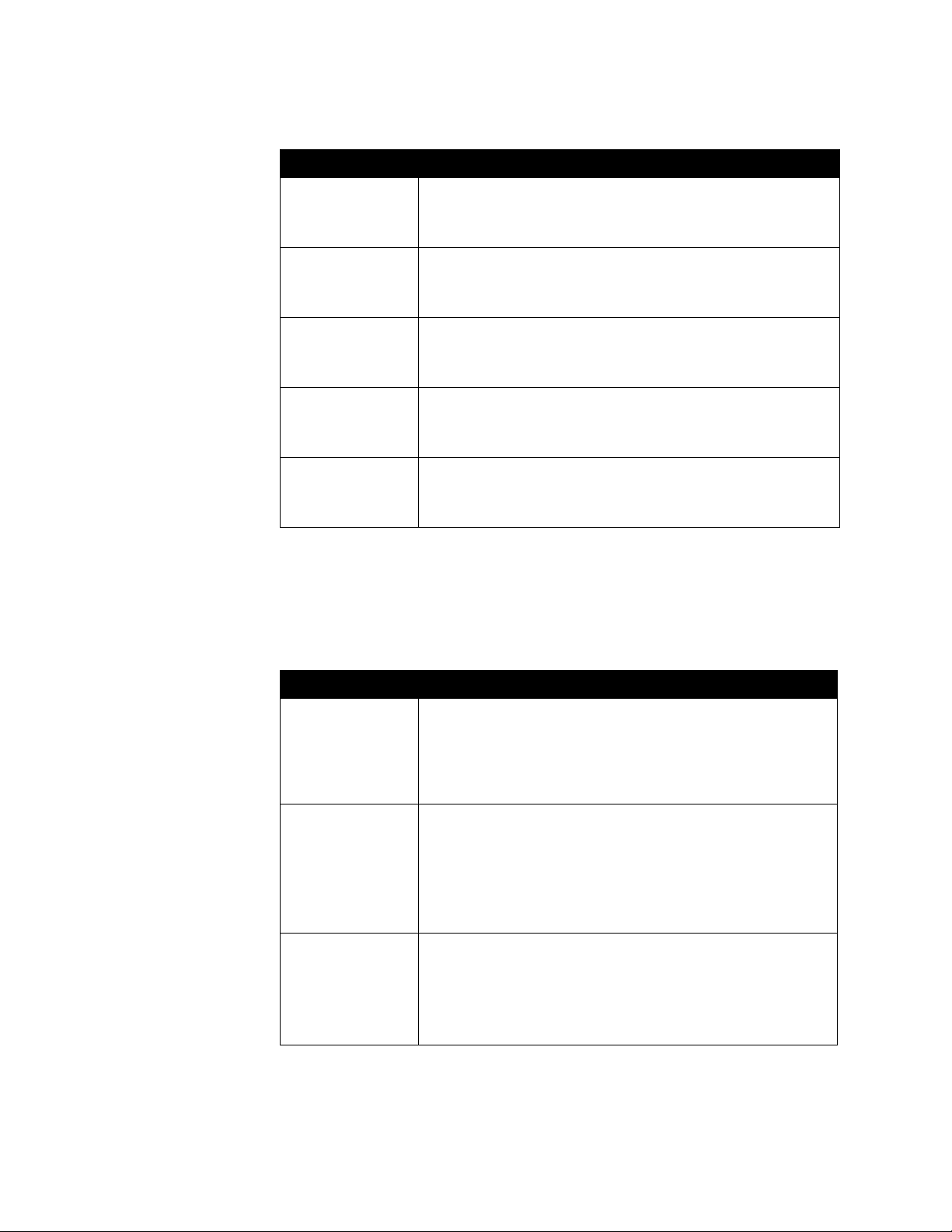
Administrator’s Guide for ViewStation EX, ViewStation FX, and VS4000
Setting Description
IP Address Displays the IP address currently assigned to the system.
If the system does not automatically obtain an IP Address, enter
the IP address here.
DNS Servers Displays the DNS servers currently assigned to the system.
If the system does not automatically obtain a DNS server addres s,
enter up to four DNS servers here.
Default Gateway Displays the gateway currently assigned to the system.
If the system does not automatically obtain a gateway IP address,
enter one here.
Subnet Mask Displays the subnet mask currently assigned to the system.
If the system does not automatically obtain a subnet mask, enter
one here.
WINS Server Displays the WINS server currently assigned to the system.
If the system does not automatically obtain a WINS server IP
address, enter one here.
To configure Advanced LAN properties:
1. Go to System Info > Admin Setup > LAN/H.323 > LAN/Intranet > Advanced
LAN Settings.
2. Configure these settings:
Setting Description
Select LAN Port Specifies whether a PC is connected to this system.
• LAN Port — No PC is connected to this system.
•PC Port — A PC is connected to this system. If the
videoconferencing system is connected to the LAN, the PC can
also access the network.
LAN Speed Specifies the LAN speed to use. Note that the speed you choose
must be supported by the switch.
Choose Auto to have the network switch negotiate the speed
automatically.
If you choose 10 Mbps or 100 Mbps, you must also select a
duplex mode.
Duplex Mode Specifies Half Duplex or Full Duplex. Note that the duplex mode
you choose must be supported by the switch.
Choose Auto to have the network switch negotiate the duplex
mode automatically.
The system restarts if you change this setting.
3-6 www.polycom.com/videodocumentation
Page 55

Chapter 3 - Configuring Network Use
Configuring the System for Use with a Firewall or NAT
A firewall protects an organization’s network by controlling data traffic from
outside the network. Unless your firewall is designed to work with H.323
videoconferencing equipment, you must configure the system and the firewall to
allow videoconferencing traffic to pass in and out of the network.
Network Address Translation (NAT) network environments use private internal IP
addresses for devices within the network, while using one external IP address to
allow devices on the LAN to communicate with other devices outside the LAN. If
your system uses a NAT, it must be assigned a public IP address to communicate
outside the LAN.
Systems deployed outside a firewall are potentially vulnerable to unauthorized access. Visit
the Polycom Security Center at www.polycom.com for timely security information. You can
also register to receive periodic email updates and advisories.
To set up the system to work with a firewall or NAT:
1. Go to System Info > Admin Setup > LAN/H.323 > LAN/Intranet >
Firewall/LAN Connection.
2. Configure these settings:
Setting Description
Use Fixed Ports Lets you specify whether to define the TCP and UDP ports.
This enables the ViewStation system to assign a range of ports
starting with the TCP and UDP ports you specify. In most cases,
the range begins with port 3230 for both TCP and UDP.
Note: You must also open the firewall’s TCP port 1720 to allow
H.323 traffic.
TCP Ports
UDP Ports
System is Behind a
NAT
NAT is H.323
Compatible
Lets you specify the beginning value for the range of TCP and
UDP Ports used by the system.
Note: You must also open the firewall’s TCP port 1720 to allow
H.323 traffic.
Lets you specify that the system obtains its IP address from the
NAT. If users connect to this system using a Virtual Private
Network (VPN), clear this field.
Lets you specify that the system is behind a NAT that allows
HTTP traffic.
Auto Discover NAT Lets you specify whether the system should determine the NAT
Public Address automatically.
The system restarts if you change this setting.
© Polycom, Inc. 3-7
Page 56

Administrator’s Guide for ViewStation EX, ViewStation FX, and VS4000
Setting Description
NAT Public (WAN)
Address
Address Displayed in
Global Address Book
Displays the address that callers from outside the LAN use to call
your system. If you chose to configure the NAT manually, enter
the NAT Public Address here.
The system restarts if you change this setting.
Lets you choose whether to display this system’s public or private
address in the Global Address Book.
3-8 www.polycom.com/videodocumentation
Page 57

Specifying H.323 Settings
If your network uses a gatekeeper, the system can automatically register its H.323
name and extension. This allows others to call the system by entering the H.323
name or extension instead of the IP address.
To specify H.323 Settings:
1. Go to System Info > Admin Setup > LAN/H.323 > H.323 > Setup.
2. Configure these settings:
Setting Description
Chapter 3 - Configuring Network Use
H.323 name when
calling this system
H.323 Extension
(E.164)
Auto H.323 Dialing Lets the system automatically detect the call type based on the
Display IP Dialing
Extension
Specifies the name that gatekeepers and gateways use to identify
this system. You can make point-to-point calls using H.323 names
if both systems are registered to a gatekeeper.
The H.323 Name is the same as the System Name, unless you
change it. Your organization’s dial plan may define the names you
can use. Each system’s name must be unique.
The system restarts if you change this setting.
Specifies the extension that gatekeepers and gateways use to
identify this system.
The default H.323 Extension is based on the system serial
number, but it can be changed. Your organization’s dial plan may
define the extensions you can use. Each system’ s extension must
be unique.
The system restarts if you change this setting.
format of the dialing information you enter. The ISDN and IP fields
are not displayed on the Video Phone screen.
Adds a field to the Video Phone screen so you can enter the H.323
extension separately from the gateway ID.
If you choose not to add a field for the extension, users can either
append the extension to the gateway number or use the Tone Pad
to enter the extension when the gateway requests it.
© Polycom, Inc. 3-9
Page 58

Administrator’s Guide for ViewStation EX, ViewStation FX, and VS4000
Configuring Dialing Speeds
Setting up dialing speeds lets you define the speeds users can choose when they
make calls or add Directory entries.
To configure the dialing speeds available to users:
1. Go to System Info > Admin Setup > LAN/H.323 > H.323 > Dialing Speeds.
2. Select the call rates that users can choose for making calls.
• Nx56 and Nx64 rates are available for ISDN calls.
• IPx56 and IPx64 rates are available for IP calls.
Configuring the System to Use a Gatekeeper
A gatekeeper supervises network traffic and manages functions such as
bandwidth control and admission control. The gatekeeper also handles address
translation, which allows users to make calls using static aliases instead of IP
addresses that may change each day.
To configure the system to use a gatekeeper:
1. Go to System Info > Admin Setup > LAN/H.323 > H.323 > Gatekeeper.
2. Configure these settings:
Setting Description
H.323 Name Specifies the name that gatekeepers and gatewa ys use to identify
this system. You can make point-to-point calls using H.323 names
if both systems are registered to a gatekeeper.
The H.323 Name is the same as the System Name, unless you
change it. Your organization’s dial plan may define the names you
can use. Each system’s name must be unique.
The system restarts if you change this setting.
H.323 Extension
(E.164)
Specifies the extension that gatekeepers and gateways use to
identify this system.
The default H.323 Extension is based on the system serial
number, but it can be changed. Your organization’s dial plan may
define the extensions you can use. Each system’s e xtension must
be unique.
The system restarts if you change this setting.
3-10 www.polycom.com/videodocumentation
Page 59

Chapter 3 - Configuring Network Use
Setting Description
Use Gatekeeper Specifies whether to use a gatekeeper. Gateways and
gatekeepers are required for calls between IP and ISDN networks.
• Off — Calls do not use a gatekeeper.
• Specify — Calls use the specified gatekeeper. Enter the
gatekeeper’s IP address or name (for example,
gatekeeper.companyname.usa.com, or
255.255.255.255).
•Auto — System automatically finds an available gatekeeper.
• The system restarts if you change this setting.
Gatekeeper IP
Address
Outbound Call
Route
Dial Multipoint Calls
from PathNavigator
Displays the gatekeeper’s IP address. If you chose to specify a
gatekeeper, enter the IP address here.
The system restarts if you change this setting.
For systems using a gatekeeper, specifies whether calls initiated
by this system should be handled as IP calls sent through a
gateway or as ISDN.
Lets you specify whether multipoint calls use the system’s internal
multipoint capability or the PathNavigator Conference on Demand
feature. This feature is available only if the system is:
• Configured for multipoint calling.
• Registered with a PathNavigator gatekeeper.
Configuring the System to Use a Gateway
A gateway performs protocol conversion between IP and ISDN networks, so that
users on different networks can call one another. If the system is configured to use
a gateway, you must also configure it to use a gatekeeper.
To configure the system to use a gateway:
1. Go to System Info > Admin Setup > LAN/H.323 > H.323 > Gateway.
2. Configure these settings:
Setting Description
Gateway Num ber
Type
Country Code Specifies the country code for the system’s location.
© Polycom, Inc. 3-11
Specifies the number type users enter to call this system:
• Direct Inward Dial (DID) — Users enter an internal extension
to call this system directly.
Note: If you choose this option, you must also register the
number with the gatekeeper as an E.164 alias.
• Number + Extension — Users enter the gateway n umber and
the system’s e x tension to call this system.
Page 60

Administrator’s Guide for ViewStation EX, ViewStation FX, and VS4000
Setting Description
Area Code Specifies the area or city code for the system’s location.
Number Specifies the gateway’s number.
Extension Specifies the extension that identifies this system for incoming
gateway calls.
The default H.323 Extension is initially based on the system serial
number, but it can be changed.
Number of Digits in
DID Number
Number of Digits in
Extension
3. Select Next and enter a prefix or suffix for each bandwidth you want to allow
for gateway calls.
Be sure to configure the gateway to use the same prefixes and suffixes you define for
the system.
Specifying Quality of Service
Set the Quality of Service options for the way your network handles IP packets
during video calls.
To specify the Quality of Service:
1. Go to System Info > Admin Setup > LAN/H.323 > QOS.
Specifies the number of digits configured by your network
administrator.
Specifies the number of digits configured by your network
administrator.
2. Configure these settings:
Setting Description
Type of Service
(ToS) Field
Type of Service
(ToS) Value
3-12 www.polycom.com/videodocumentation
Lets you choose your service type.
Specifies the value of the Type of Service (ToS) byte in the IP
packet header for video , audio, and f ar-end camera control. These
values are supported:
Type of Service Minimum Value Maximum Value
IP Precedence: 0 5
Diffserv: 0 63
Page 61

Setting Description
Chapter 3 - Configuring Network Use
Dynamic
Bandwidth
Enable PVEC Allows the system to use PVEC (Polycom Video Error
Specifies whether to let the system automatically find the optimum
line speed for a call if packet loss occurs.
Concealment) if packet loss occurs.
Configuring ISDN Support
You can add one optional network interface module to the system. This lets you
extend the functionality of the system so that you can:
❑ Make ISDN calls over a PRI/T1 network (in North America) or PRI/E1
(outside of North America).
❑ Make ISDN calls over a BRI network.
❑ Connect encryption or other third-party network equipment using a Serial
V.35/RS-449/RS-530 interface.
This section describes the settings for all optional network interfaces and identifies
the settings that are available only for specific network interfaces.
You can configure a network interface only if the corresponding network interface
module is installed. The system automatically detects the module and displays
only the required configuration screens.
Configuring Inverse Multiplexer (IMUX) Settings
You must configure the IMUX settings for Quad BRI and PRI only. If your system
uses the V.35/RS- 449/RS-530 network interface, skip this section.
© Polycom, Inc. 3-13
Page 62

Administrator’s Guide for ViewStation EX, ViewStation FX, and VS4000
To configure Inverse Multiplexer (IMUX) settings:
1. Go to System Info > Admin Setup > Video Network > IMUX.
2. Choose each icon and configure the settings on the corresponding screens:
Choose... Then do this...
Numbers 1. Specify the area code for this system’s location.
2. Specify the numbers assigned to the B1 and B2 channels for
each line.
The two numbers for a line may be the same or different,
depending on the switch protocol in use.
SPIDs
(for Quad BRI with
NT-1 device only)
Audio Quality Specify the minimum bandwidth allowed for calls using the G.722
Advanced Dialing Specify whether to dial the ISDN channels all at once or one at a
Dialing Speeds Select the call rates that users can choose for making calls.
1. If the system is on a PBX, select PBX. You will not need to do
any further configuration on this screen.
Note: The PBX selection is not available on the web interface. If
you are configuring the system from the web interface, and the
system is on a PBX, skip this screen.
2. If the system is not on a PBX, and you have configured ISDN
switch protocol to be AT&T 5ESS Multipoint, NI-1, or Nortel
DMS-100, specify the system’s SPIDs . The system then verifies
the numbers. If the system is unable to verify the SPIDs, mak e
sure the system is connected and that the ISDN numbers you
entered are correct.
If the system is located in the United States or Canada, you can
have the system detect the SPIDs automatically.
3. Select Start.
algorithm. All calls below this bandwidth use the G.728 algorithm.
time.
If you choose to dial channels one at a time, each channel is
dialed only after the previous channel connects Use this setting if
you experience problems dialing all channels at once.
• Nx56 and Nx64 rates are available for ISDN calls.
• IPx56 and IPx64 rates are available for IP calls.
3-14 www.polycom.com/videodocumentation
Page 63

Configuring the Quad BRI Network Interface
To configure the ISDN Network settings:
1. Go to System Info > Admin Setup > Video Network > ISDN Network.
2. Configure these settings:
Setting Description
Country Code Specifies the country code for this system’s location.
Area Code Specifies the area code or STD for this system’s location.
Chapter 3 - Configuring Network Use
Number A
Number B
ISDN Switch
Protocol
ISDN Dialing Prefix Specifies the number to dial to access numbers outside the PBX.
Specifies the primary and secondary ISDN numbers assigned to
this system.
Specifies the ISDN switch protocol used by the network. Contact
your ISDN network service provider for this information.
If the system is not located on a PBX, leave this field blank.
Configuring the PRI Network Interface
To use the PRI network interface, you must configure the following:
❑ PRI network support
❑ PRI channels
❑ PRI information
Your ISDN service provider can tell you which protocol your network uses. If you later
change the country setting, the PRI switch protocols available may also change, and you
may be prompted to configure a different PRI switch protocol.
© Polycom, Inc. 3-15
Page 64

Administrator’s Guide for ViewStation EX, ViewStation FX, and VS4000
To set up PRI network support:
1. Go to System Info > Admin Setup > Video Network > IMUX > PRI Network
> PRI Setup.
2. Configure these settings:
Setting Description
Line Signalling Specifies the framing format in use.
This setting is configurable for PRI E1, read-only for PRI T1.
CSU
(PRI T1 only)
Line Build Out
(PRI T1 only)
Switch Protocol Specifies the Network switch protocol. The available choices are
Specifies whether this system uses an external or internal
Channel Service Unit (CSU).
For systems using an internal CSU, indicates the output
attenuation in dB. Your service provider can provide you with
these values.
For systems using an external CSU, indicates the length (in feet)
of the RJ-45 cable that connects the PRI network interface module
to the CSU.
determined by the system’s country settings.
This setting is read-only for PRI E1, configurable for PRI T1.
3. Select Advanced PRI Setup and configure these settings:
Setting Description
Restore Default Resets all values on this screen. This does not affect other PRI
settings.
Numbering Plan Select the appropriate numbering plan for your location, if it differs
from the default.
International
Dialing Prefix
Call-by-Call Specifies a code that the system sends to the telephone company
Specify the dialing prefix needed for international calls.
switch to request a special service, if such a code is required.
Consult your telephone service provider to determine the proper
call-by-call value.
3-16 www.polycom.com/videodocumentation
Page 65
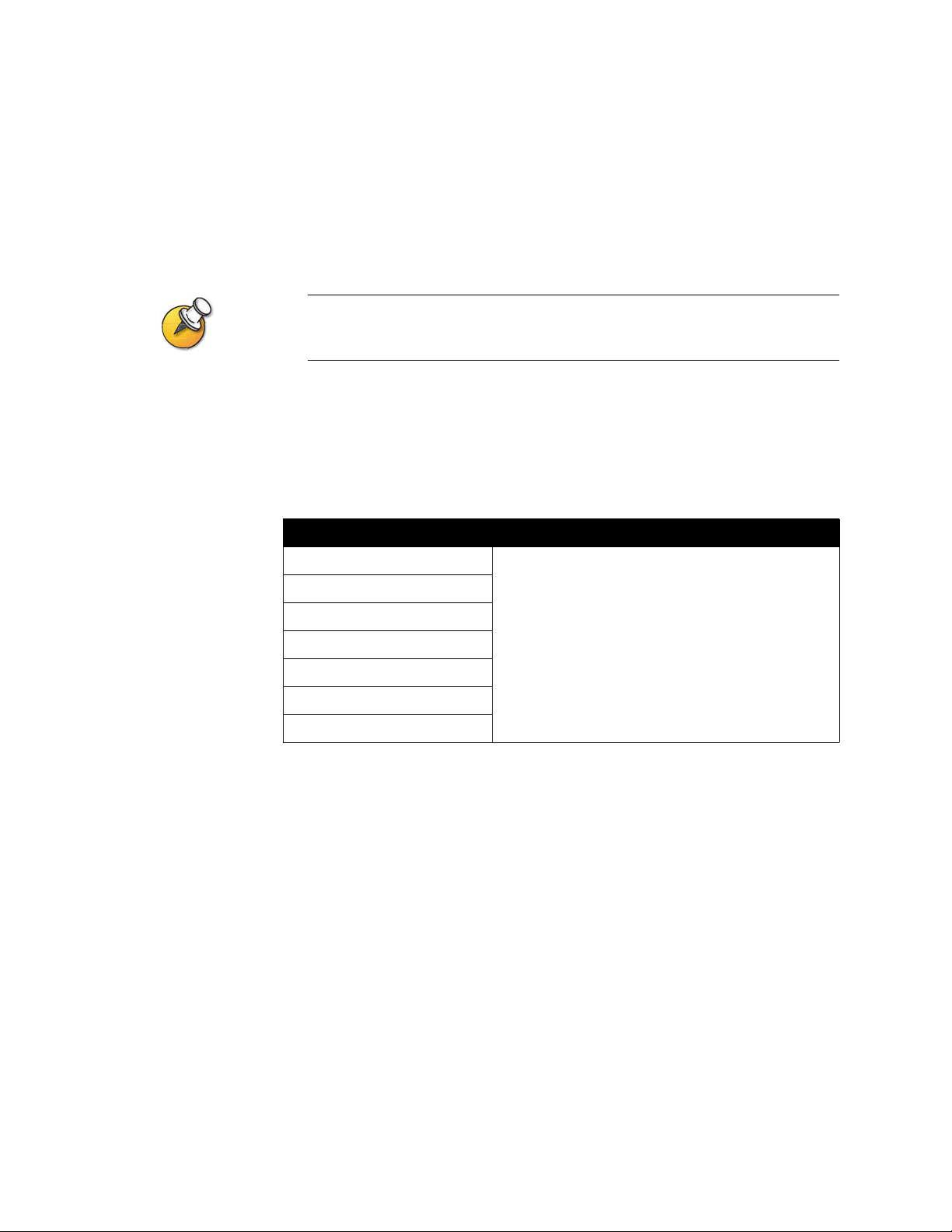
Chapter 3 - Configuring Network Use
To configure the PRI channels:
1. Go to System Info > Admin Setup > Video Network > IMUX > PRI Network
> PRI Status.
2. Select a channel to activate or deactivate it. Active channels are represented by
a green icon, and inactive channels are represented by a gray icon.
Channels should be activated and deactivated only by a knowledgeable network
professional.
To access PRI Information:
1. Go to System Info > Admin Setup > Video Network > IMUX> PRI Network
> PRI Information.
2. You can view the following read-only information:
Setting Description
PRI Line Type Displays read-only information about the system and
Number of Active Channels
D Channel Location
Network Mode
Clock Source
Termina l Endpoint ID (TEI)
Line Termination (PRI E1 only)
its configuration.
© Polycom, Inc. 3-17
Page 66

Administrator’s Guide for ViewStation EX, ViewStation FX, and VS4000
Configuring the Serial V.35/RS-449/RS-530 Network Interface
To use the serial network interface for the system, you may need to configure the
following:
❑ Video network settings
❑ Network control signals
❑ Calling profile
❑ Broadcast Mode
❑ Dialing speeds
❑ Crypto Resync
To configure serial video network settings:
1. Go to System Info > Admin Setup > Video Network > Video Network.
2. Configure these settings:
Setting Description
RS-366 Dialing Allows users to dial calls from this system.
Uncheck this box if this is a dedicated connection or if
another device is used for dialing calls.
V.35 Ports Used Specifies whether one or two lines are connected.
Dialing Protocol Specifies the protocol used by this system.
Broadcast Mode Enab les support for H.331 broadcast transmissions from
this system.
This enables the system to send video and audio to many
other system, such as large satellite networks.
3-18 www.polycom.com/videodocumentation
Page 67
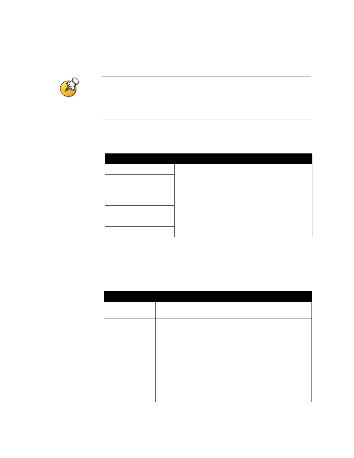
Chapter 3 - Configuring Network Use
To configure serial interface control signals:
The system can provide standard or inverted signal polarity. Refer to the documentation
supplied with the device you have connected to the V.35/RS-449/RS-530 network interface
module to determine whether you need to change signal polarity. Do not change signal
polarity unless your equipment requires it. Incorrect signal polarity settings will prevent the
equipment from working properly.
1. Go to System Info> Admin Settings > Video Network > Advanced V.35.
2. Configure these settings:
Setting Description
ST Lets you specify the signaling required by the external
RT
RTS
device connected to the system. Specify normal or
inverted, as appropriate. In most cases, normal signaling
is appropriate.
DCD
CTS
DTR
DSR
To choose a calling profile for the connected equipment:
1. Go to System Info > Admin Setup > Video Network and enable RS-366
Dialing.
2. Select Advanced Dialing and configure these settings:
Setting Description
Prefix Lets you specify the dialing prefix required to reach an outside
line.
Calling Profile Lets you specify what data communications equipment is
connected to the network interface. The system automatically
displays the default prefixes, suffix es, and calling speeds required
by that device.
If your device is not listed, choose Custom.
Speed Lets you define the prefixes or suffixes to use f or each speed used
in a Custom Calling Profile. For information about required
prefixes and suffixes, see the documentation that came with the
device.
If you choose a predefined Calling Profile, this information is
supplied for you.
© Polycom, Inc. 3-19
Page 68
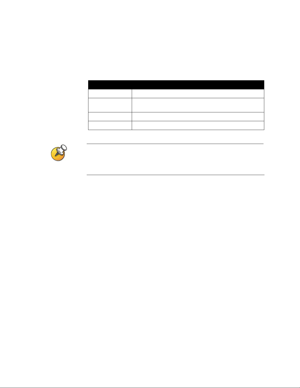
Administrator’s Guide for ViewStation EX, ViewStation FX, and VS4000
To configure Broadcast Mode settings:
1. Go to System Info > Admin Setup > Video Network > Video Network and
enable Broadcast Mode.
2. Select Broadcast Mode Setup and configure these settings:
Setting Description
Video Format Specifies the resolution at which video is transmitted.
Video Protocol Specifies the protocol used to transmit video. Choose the lowest
protocol supported by all systems in the conference.
Audio Mode Specifies the protocol used to transmit audio,
Fram e Ra te Specifies the frame rate to use.
In Broadcast Mode, the system sends and receives audio and video without handshaking
with the far end systems. This enables the system to send transmissions to many systems
at once, such as satellite networks. In this mode, the system does not receive audio and
video from all far site systems.
To select dialing speeds:
1. Go to System Info > Admin Setup > Video Network and enable RS-366
Dialing.
2. Select Dialing Speeds and select the call rates that users can choose for making
calls.
• Nx56 and Nx64 rates are available for ISDN calls.
• IPx56 and IPx64 rates are available for IP calls.
3-20 www.polycom.com/videodocumentation
Page 69
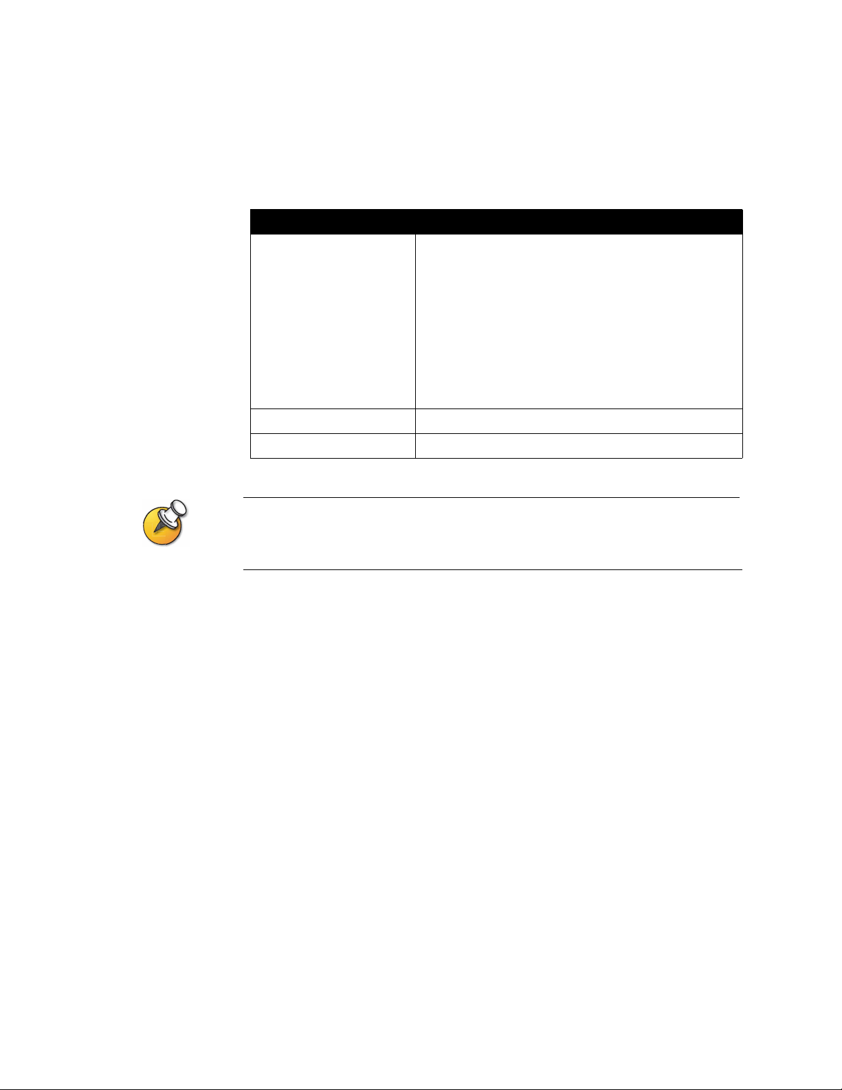
Chapter 3 - Configuring Network Use
To configure crypto resync:
1. Go to System Info > Admin Setup > Security > Crypto Resync.
2. Configure these settings:
Setting Description
Crypto Resync Allows a system connected to cryptographic equipment to
signal when it loses video synchronization during a call.
The cryptographic equipment can then resynchronize
with the far end.
When this option is enabled, the resynchronization pulses
are sent out on the RTS signal.
To use this option, the cable to your cryptographic
equipment should route the V .35/RS-449/RS-530 network
interface module’s RTS signal to the appropriate resync
input on the cryptographic equipment.
Time Between Pulses (sec) Specifies the time between resync pulses in seconds.
Pulse Width (millisec) Specifies the pulse duration in milliseconds.
You may need to use crypto resync when you connect a cryptographic coder/decoder
between the system and the network. This allows the system to signal the cryptographic
device when video synchronization is interrupted.
© Polycom, Inc. 3-21
Page 70

Administrator’s Guide for ViewStation EX, ViewStation FX, and VS4000
Configuring the Global Address Book
If your organization uses the Polycom Global Management System, you can
configure your system to use the Global Address Book. The Global Address Book
provides a list of other systems that are registered with the Global Directory Server,
and available for calls. The other systems appear in the Address Book, allowing
users to place calls to other users by selecting their names.
Configuring the Global Address Book Server Settings
To configure the Global Address Book Server settings:
1. Go to System Info > Admin Settings > LAN/H.323 > Global Address >
Server.
2. Configure these settings:
Setting Description
Server IP Address Specifies the IP address or DNS name of the Global Address
Book Server.
Server Password Lets you enter the Global Directory password, if there is one.
Connected Indicates whether the system is connected to the Global Address
Book Server.
OneDial Available Indicates whether the Polycom OneDial feature can be used.
Display Global
Addresses
Register This
System When
Power ed On
Displays other registered systems in this system’ s Global Address
Book.
Specifies whether to display this system’s name in the Global
Address Books of other registered systems.
3-22 www.polycom.com/videodocumentation
Page 71

Setting Global Address Book Preferences
The available display and dialing preferences are determined by the call types and
gatekeepers configured for this system. Depending on how your system is
configured, you may not see all of the settings described in this section.
To set the Global Address Book preferences:
1. Go to System Info > Admin Settings > LAN/H.323 > Global Address >
Preferences.
2. Configure these settings:
Setting Description
Chapter 3 - Configuring Network Use
Show Addresses in
Address Book
Maximum Line
Speed for Global
Addresses
Preferred Alias
(E.164)
Lets you specify whether to show IP addresses, ISDN addresses,
or both in the Address Book. You can choose from the call types
you specified on the Video Call Preferences screen.
Specifies the line speeds to use for calling the Global Address
Book numbers displayed in this system’s Address Book. You can
set a different speed for each type of address.
These settings do not apply to local entries you add to the Address
Book on this system.
Specifies the numeric extension or telephone number that you
want outside systems to use to reach this system. This option is
only available if you have registered your system with a
Gatekeeper and the Global Address Book server.
To select the Preferred Alias:
1. Select this field to display the Preferred Alias screen.
2. Select the alias you want to register with the Global Directory
Service.
Your choices are determined by the Gateway Number Type
configured for this system:
Gateway Number Type Possible Alias
Direct Inward Dial (DID) ISDN number (for native ISDN)
Full DID number
DID number provided by switch
DID extension
H.323 extension
Number + Extension ISDN number (for native ISDN)
H.323 extension
© Polycom, Inc. 3-23
Page 72
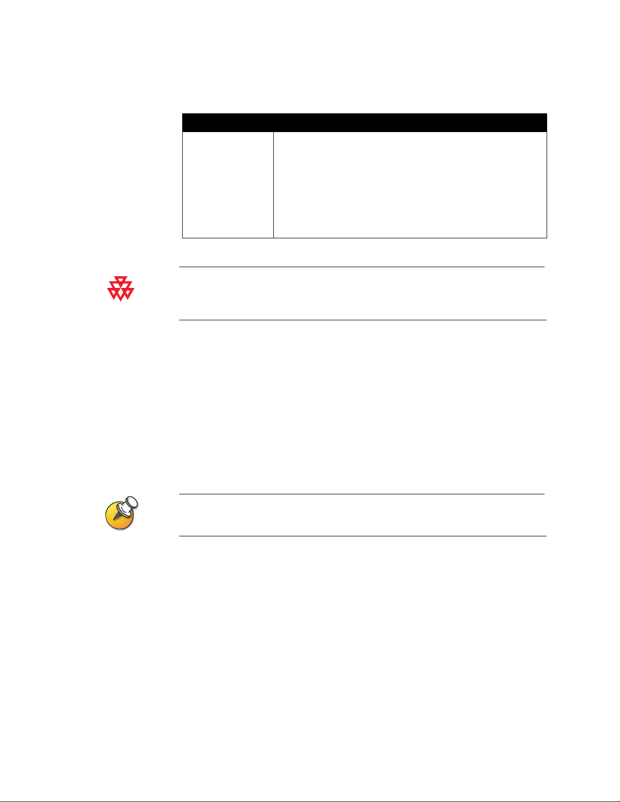
Administrator’s Guide for ViewStation EX, ViewStation FX, and VS4000
3. Select OneDial Preferences and configure these settings:
Setting Description
Primary Call Type
Choice
Secondary call
Type Choice
Polycom OneDial™ simplifies placing videoconferencing calls by negotiating bandwidths,
determining alternate routing, and allowing conference on demand. Your system must be
configured to use PathNavigator to use OneDial calling.
Allows you to specify how to place calls - IP or ISDN.
For Directory entries containing both IP and ISDN numbers, the
system places the type of call you have specified as the primary
call type. You can specify a call type to use when the primary call
type is not avai labl e, or y ou can specif y None if you wish users to
place calls only by IP or only by ISDN.
If you choose Manual for the primary call type, the system
prompts the user to choose a call type.
Configuring the System for Use on a Private Network
The Private Network ISDN Number provides a second number that can be used to
call the system. If an organization’s PBX has two different lines coming from
different network providers, the Private Network Number identifies the
additional lines needed after the first line connects.
The Private Network Number can also signal the PBX to route additional calls
through the PBX instead of going outside the PBX through the trunk line.
Some PBX systems signal the same called number regardless of the number used to call
an endpoint. In this situation, the private number method may not work.
To configure the system for a Private Network:
1. Go to System Info > Admin Setup > LAN/H.323 > Global Address > Private
Net.
2. Enter the Private Network Numbers for each line.
3-24 www.polycom.com/videodocumentation
Page 73
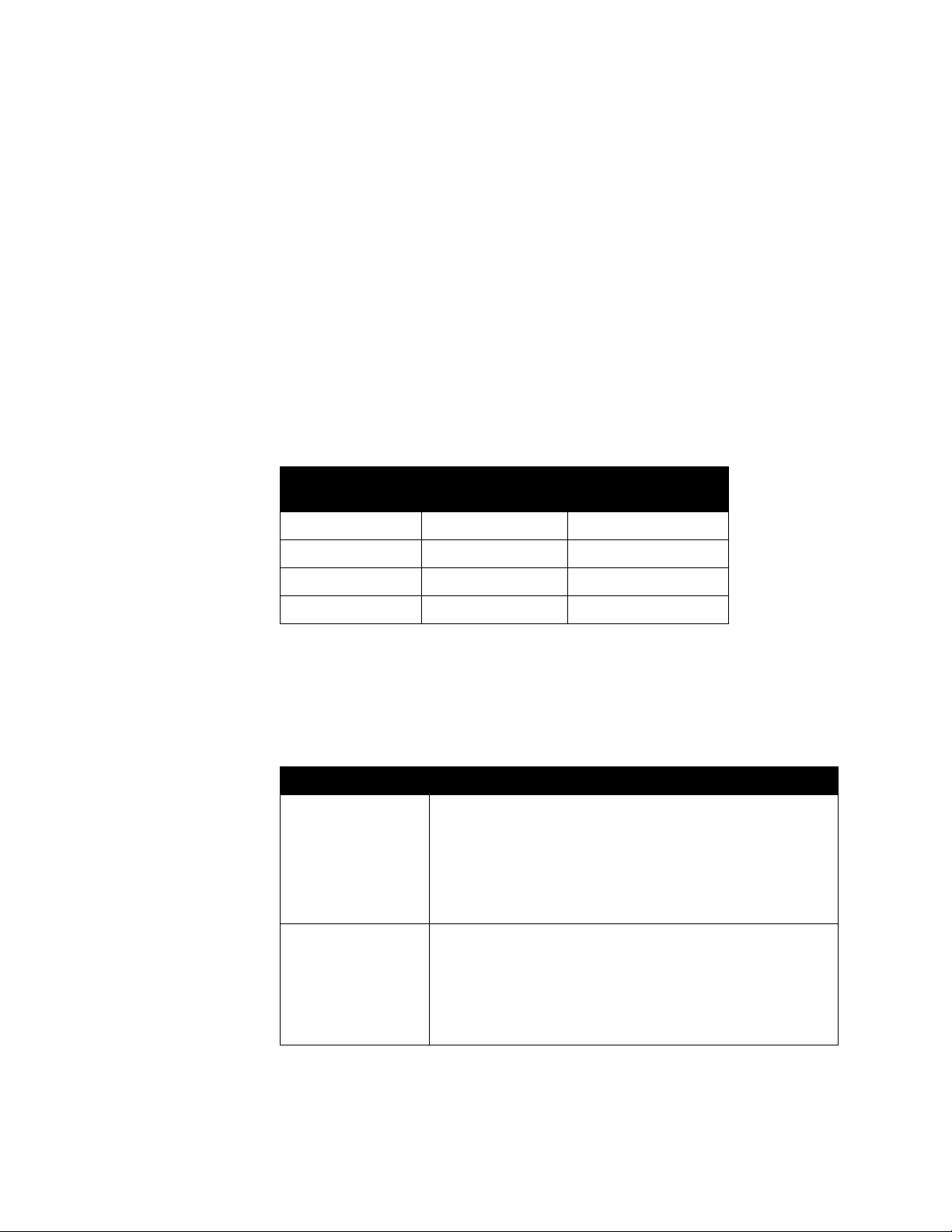
Setting the Dialing Rules
If your system is connected to your organization’s private network and also to a
public network, you may need to specify the codes and prefixes necessary for
dialing other systems. If your system is connected only to a public network, you
do not need to enter any dialing rules.
When you define dialing rules, your system’s Address Book can display dialing
information about other videoconferencing systems correctly, including all of the
numbers, area codes, country codes, and international dialing access codes
necessary for making calls from this system. For example, if your system is in
Melbourne, the Address Book displays the correct numbers and codes for dialing
systems in Paris, New York, and Cape Town, just as they should be dialed from
Melbourne.
When you place a call using the Global Address Book, your system chooses the call
type using these guidelines:
Chapter 3 - Configuring Network Use
If You Call From
This Network:
Public Network Public Network Public Network
Public Network Private Network Public Network
Private Network Public Network Public Network
Private Network Private Network Private Network
To This Network: Your System Places
the Call Using:
To set the dialing rules:
1. Go to System Info > Admin Setup > LAN/H.323 > Global Address > Dialing
Rules 1.
2. Configure these Dialing Rules:
Setting Description
Number of Digits in
Extension
Specifies the number of digits in the extension used to call other
systems with the same area code (or city code) and prefix.
For example, if your system’s number is 1-512-555-1212 and
you can call a system at 1-512-555-1214 by entering 51214,
your exten s i o n ha s 5 di g i ts.
Leave this field blank if the system is not connected to a PBX.
International Dialing
Prefix
© Polycom, Inc. 3-25
Specifies the prefix to use for placing international calls. This
prefix is automatically added to international calls made from the
Global Directory.
Note that this overrides the international dialing prefix for the
country specified in Syst em Info > Admin Setup > General
Settings > Country.
Page 74

Administrator’s Guide for ViewStation EX, ViewStation FX, and VS4000
Setting Description
Public Network
Allows your system to use a public network for making calls.
Access
Public Network
Dialing Prefix
Specifies the prefix required by your PBX for calls that use the
public network.
This prefix is automatically inserted before dialing public network
numbers from the Global Directory.
Public Network
(same area code)
Specifies the prefix to use for public network calls between
systems in the same area code.
Prefix
Private Network
Access
Allows this system to use a private network for making calls.
When you enable private network access, the Global Address
Book displays private network numbers f or all systems that also
allow private network access.
Private Network
Dialing Prefix
Specifies the prefix to use to call another system on the same
private network.
3. Go to System Info > Admin Setup > LAN/H.323 > Global Address > Dialing
Rules 2:
Setting Description
If Area Code = ___ Dial Prefix ___ Lists the prefix to use in place of the area code
specified.
Always Dial Area Code Specifies that calls to sites in the same area code
must include the area code.
Dial 1+ for all USA calls Specifies that calls to systems in the United States
must include a “1” before the area code.
3-26 www.polycom.com/videodocumentation
Page 75

Placing a Test Call
When you finish configuring the system, you may wish to place a call to test your
setup.
You can find a list of worldwide numbers that you can use to test your system at
www.polycom.com/videotest.
To place a test call:
1. Select Video Call from the main screen.
2. Enter the ISDN number, system name or IP address.
To enter text, press Keyboard to access the onscreen keyboard.
Chapter 3 - Configuring Network Use
3. Enter a second ISDN number, if necessary.
4. Select the call type.
5. Select the call speed.
6. Press Call-Hang Up on the remote control.
If you have trouble making video calls:
❑ Make sure the number you dialed is correct, then try the call again. For
example, you may need to dial 9 for an outside line or include a long distance
access code or country code.
❑ To find out if the problem exists in your system, ask the person you were trying
to reach to call you instead.
❑ Find out if the system you are calling has its power turned on and is
functioning properly.
❑ If you can make calls but not receive them, make sure that your system is
configured with the correct number.
© Polycom, Inc. 3-27
Page 76

Administrator’s Guide for ViewStation EX, ViewStation FX, and VS4000
Keeping your Software Current
If you have Internet access, you can use the web-based Softupdate application to
upgrade the system software. If you do not have Internet access, your reseller can
supply you with the updated software on CD-ROM.
Before you begin, read the Release Notes, available at www.polycom.com/videosoftware,
for the latest information about your software version.
The following diagram shows the overall process of updating software.
Update your system
www.polycom.com
softupdate.exe
Update additional systems
ISDN
The following table describes how to update your system.
To complete this task... In this way... Do this:
Install the software update
application on a computer
From the software CD Place the CD in your computer’s CD drive.
From the web 1. Open a browser and go to www.polycom.com.
2. Go to the Software Downloads area and
navigate to your product.
3. Select the appropriate Release Code.
4. Log in to the Polycom Resource Center.
5. Navigate to the ViewStation EX, FX, and
VS4000 Downloads and select the current
software release.
6. When the system prompts you to open or save
the file, click Save.
7. In the Save As window, clic k Sa ve to place the
.zip file on your desktop, or specify where to
save it.
8. Open the .zip file and extract softupdate.exe.
3-28 www.polycom.com/videodocumentation
Page 77

Chapter 3 - Configuring Network Use
V
To complete this task... In this way... Do this:
Connect to the system From your organization’s LAN Verify that the computer and the system are both
connected to the LAN - for example, b y opening a
command line on the computer to ping the
system.
Directly to a system on a LAN Connect a LAN cable from the computer’s LAN
port to the system’s PC LAN connector, shown at
the left.
PC LAN
Directly to a system that is not
on a LAN, configuring static IP
addresses manually
X
Directly to a system that is not
on a LAN, configuring the
system to provide the
computer’s IP address
T o use this method, the system
must have been configured as
a DHCP server during the
previous software update.
1. Connect a LAN cable from the computer’s LAN
port to the system’s PC LAN connector , shown
at the left.
2. On the system, select System Info >
Admin Setup > LAN/H.323 > LAN/Intranet >
LAN & Intranet.
3. In the DHCP field, select Off.
4. Enter the following:
IP Address: 1.1.1.2
Default Gateway: 1.1.1.1
Subnet Mask: 255.255.255.0
5. Configure your computer to use a static IP
address:
IP Address: 1.1.1.3
Subnet Mask: 255.255.255.0
1. Connect a LAN cable from the computer’s LAN
port to the system’s PC LAN connector , shown
at the left.
2. On the system, select System Info >
Admin Setup > LAN/H.323 > LAN/Intranet >
LAN & Intranet.
3. In the DHCP field, select Server. When the
system displays the confirmation message,
select Yes.
4. When you navigate out of this screen, the
system displays a message asking if you want
to save the changes. Select Yes to sa ve the
changes and restart the system.
Note: Do not use this setting if the ViewStation
FX or VS4000 is connected to a LAN with a
DHCP server.
The setting will not take effect if the system is
on a LAN with an active DHCP server.
If the system has previously been configured
as a DHCP server, it reverts to being a DHCP
client when it is connected to a LAN and
restarted.
© Polycom, Inc. 3-29
Page 78

Administrator’s Guide for ViewStation EX, ViewStation FX, and VS4000
To complete this task... In this way... Do this:
Update the system’s
software
Update ISDN systems at
other sites
From the computer 1. Start the Softupdate.exe application.
2. Enter the system’s IP address.
3. If necessary, enter the system’s administrator
password.
4. If you wish to delete the system’s Address
Book, select Remove Address Book Entries.
5. If you wish to restore the factory settings during
the update, select Remove System Files. This
clears information such as the system name
and network configuration settings.
6. If the system is not connected to a LAN and you
wish to allow it to issue an IP address to the
computer, select Allow System to be a DHCP
Server.
Note: Do not use this setting if the
ViewStation FX or VS4000 is connected to a
LAN with a DHCP server.
The setting will not take effect if the system
is on a LAN with an active DHCP server.
If the system has previously been
configured as a DHCP server, it reverts to
being a DHCP client when it is connected to
a LAN and restarted.
From the updated system
Note: You will need the
administrator password and
the software update
password for each system
that you update.
1. From the updated system, place an ISDN call
to another ViewStation EX, ViewStation FX, or
VS4000 system.
2. After the call connects, go to the main screen
and select System Info > Admin Setup.
3. Enter the administrator password (if any) and
select Software/Hardware > Update.
4. Select Start. If the system prompts you for the
far site’s password, enter it and select Start
again.
The call ends when the data transfer is complete.
The far-site system takes about four minutes to
rewrite its system files and restart.
Do not power off the system during the software upgrade process. If the upgrade is
interrupted, the system may lose its system files. If this happens, you will need to do the
software upgrade again and run the setup wizard to configure the system.
3-30 www.polycom.com/videodocumentation
Page 79

4
Designing the User Experience
Every organization has users with different needs. You can customize the behavior
of the system and build in various access levels for your users, depending on how
much or how little you want them to change system behaviors.
When you set up the system for the first time, the system is configured with the
most commonly used settings. If you need to change any of these initial settings,
you can adjust the screen settings as described in this chapter.
If you established an administrator’s password during the initial configuration,
you must enter it each time you change advanced settings.
What’s in this Chapter? Page
Managing User Access to Settings and Features 4-2
Designing Video and Audio Behaviors 4-5
Configuring Data Conferences and Streaming Calls 4-13
Designing General System Behaviors 4-16
Helping Users Get Started 4-25
© Polycom, Inc. 4-1
Page 80

Administrator’s Guide for ViewStation EX, ViewStation FX, and VS4000
Managing User Access to Settings and Features
You can manage user access to settings and features by using passwords and by
configuring the system to show only those options you want your users to see.
To maintain this
security level... You can allow users to...
High Call only the numbers you specify in the Address Book.
Medium Make changes to common user preferences by allowing access
to the User Setup screen. See Letting Users Customize the
Workspace on page 4-4.
Place calls using the restrictions you specify for length of call,
type of call, and use of the Address Book. See Limiting What
Users Can Do With the System on page 4-5.
Low Configure all system settings. If you choose not to set an Admin
Pass w o rd, users will ha ve access to all system settings.
Setting the Admin Password
You set an administrator’s password to restrict who can:
❑ Make changes other than those in the User Settings screen
❑ Update the software
❑ Perform remote management using the web interface
To set or change the Admin Password:
1. Go to System Info > Admin Setup > Security.
2. Enter or change the admin password.
To reset a forgotten Admin Password:
1. Get the system’s serial number from the system or from the System
Information screen.
2. Go to System Info > Diagnostics > Reset System.
3. Enter the system’s serial number and select Delete System Files.
4. Select Reset System.
When the system completes the reset, it leads you through the setup wizard. You
can enter a new Admin Password when you set up the system.
4-2 www.polycom.com/videodocumentation
Page 81

Chapter 4 - Designing the User Experience
Screens that Require the Admin Password for Access
The following diagram shows top-level system screens for the ViewStation system.
All screens within Admin Setup require the administrator’s password.
Admin Setup Diagnostics
General
- Numbers
- SPIDS
- Audio Quality
- Advanced
Video
IMUX
Call
Multipoint
ISDN
LAN/H.3
LAN/Intran
H.323
Streaming
NTP
SNMP
Global
Global
Data
- LAN & Intranet
- Advanced LAN
- Setup
- Dialing
Speeds
- Server
- Preferences
- Private Net
- Dialing
- Setup
- Info 1
User Setup
Phone/Au
Video/Came
TV Monitors
Graphics
Cameras
VCR
Securit
Software/
RS-23
Software
Hardware
System
Quality of
© Polycom, Inc. 4-3
Page 82

Administrator’s Guide for ViewStation EX, ViewStation FX, and VS4000
Letting Users Customize the Workspace
You can allow users to change common user preferences by providing access to the
User Setup screen.
1. Go to System Info > Admin Setup > General Setup, then select .
2. Check the Allow User Setup option to make the User Setup option available
to users on the System Info screen.
User Setup includes the following options:
❑ Auto-Answer Point to Point
❑ Auto-Answer Multipoint
❑ Mute Auto-Answer Calls
❑ PIP adjustment
❑ Far Control of Near Camera
❑ Backlight Compensation
❑ Allow Remote Monitoring
❑ Meeting Password
❑ Far Site Name Display Time
❑ Multipoint Mode
Some of these options are also available to administrators on the Admin Settings screens.
4-4 www.polycom.com/videodocumentation
Page 83

Limiting What Users Can Do With the System
You can limit what you allow users to do with the system by configuring the
following:
❑ Maximum time in call — Go to System Info > Admin Setup > General Setup
and specify the maximum call length allowed.
❑ Allow Dialing — You can prevent users from making calls to destinations
other than those listed in the Address Book. Go to System Info > Admin
Setup > General Setup and clear the Allow Dialing option. Users can make
calls from the Address Book but cannot access the Video Phone screen to enter
other video numbers.
❑ Allow H.320 and H.323 Mixed Calls — If you do not want to allow mixed
protocol calls on your system, go to System Info > Admin Setup > Video
Network > Call Preferences, and clear this option.
❑ Allow Address Book changes — If you do not want users to save changes to
the local address book of the system, go to System Info > Admin Setup >
General Setup and clear this option.
Chapter 4 - Designing the User Experience
❑ Allow Modifications to Camera Presets — If you have set presets on the
sytem and you do not want users to change or delete them, go to System
Info > Admin Setup > General Setup and clear this option.
Designing Video and Audio Behaviors
You can configure the following video and audio behaviors to accommodate your
environment:
❑ Camera Settings
❑ TV Monitors
❑ Content Display
❑ VCR Options
❑ Telephone and Audio Settings
❑ Touch Panel Control Settings
❑ Displaying Closed Captions
© Polycom, Inc. 4-5
Page 84

Administrator’s Guide for ViewStation EX, ViewStation FX, and VS4000
Configuring Camera Settings
The Cameras screen lets you specify camera settings, as appropriate for the
equipment you are using.
To configure camera settings:
1. Go to System Info > Admin Setup > Video/Cameras > Cameras.
2. Configure these settings:
Setting Description
Far Control of Near
Camera
Backlight
Compensation
Enable Snapshot Allows users to take snapshots, using the remote control, during
Snapshot Camera Lets you specify the camera that is used to take snapshots during
Camera Direction Specifies the direction the camera moves when using the arrow
Primary Camera Specifies whi ch came ra is the main camera.
High Resolution
Cameras
Specifies whether the far site can control the position of the
near-site camera. When this option is selected, a user at the far
site can control the framing and angle of the camera for the best
view of the near site.
Specifies whether to have the camera automatically adjust for a
light background. Backlight compensation is best used in
situations where the subject appears darker than the background.
calls.
calls.
buttons on the remote control.
Lets you specify which cameras are high resolution cameras. If
you are using a document camera or a VCR, choose high
resolution for crisper images.
To set up cameras (VS4000 only):
1. Go to System Info > Admin Setup > Video/Cameras > Cameras > VS4000
Camera Setup.
2. Specify the following camera settings for each camera you are connecting to
the VS4000:
• Camera number
• S-video or composite connection
• Pan/Tilt/Zoom capability
4-6 www.polycom.com/videodocumentation
Page 85

You can connect four cameras to your VS4000 system. Up to three cameras can use
S-video. Two cameras can be set for pan/tilt/zoom capability.
Configuring TV Monitors
The system allows you to customize displays to suit your room and equipment
configuration, including choosing the monitor for presenting content.
To configure TV monitors:
1. Go to System Info > Admin Setup > Video/Cameras > TV Monitors.
2. Configure these settings:
Setting Description
Chapter 4 - Designing the User Experience
Display Icons in a
Call
Snapshot Timeout Lets you choose whether to have snapshots and slides time out,
Number of
Monitors
PIP Specify PIP (Picture-in-Picture) behavior:
60 fields/sec at
>=512Kbps:
(Wide Screen
Video)
Specifies whether to display all on-screen graphics, including
icons and help text, during calls.
after a period of four minutes, and return to live video.
Do not select this option if you want the user to control the return
to live video by pressing the Near button on the remote control.
Specifies the number of monitors connected to the system.
•On — The PIP window stays on for the duration of the call.
•Off — The PIP window is not displayed during the call.
•Auto — The PIP is displayed when a use r pi cks up the remote.
Note: PIP settings are also available in the User Settings screen.
Specify whether to use the wide screen video option for calls using
bandwidth of 512Kbps or more.
© Polycom, Inc. 4-7
Page 86

Administrator’s Guide for ViewStation EX, ViewStation FX, and VS4000
Configuring the Content Display
You can configure the ViewStation system to display content on a TV monitor or a
high-resolution display.
To configure the content display:
1. Go to System Info > Admin Setup > Video/Cameras > Graphics Monitor.
2. Configure these settings:
Setting Description
TV Monitor Specify that video and content is displayed on the main TV monitor
connected to the system.
FX VGA Specify the following settings f or high-resolution content displa y if
you have a VGA monitor or projector connected to the system:
• VGA Output with No Graphics — Specify screen appearance
when there is no content to display.
•VGA Resolution — Specify the VGA resolution for your monitor.
The system allows you to specify up to 1280 x 1024 resolution.
Select the maximum VGA resolution that your monitor or
projector can support. Consult the user manual provided with
the VGA monitor or projector for this information.
VCFX VGA Display Specify the required behavior if you have a VGA monitor or
projector connected directly to the Visual Concert FX unit:
• Send content when PC connected — Specifies whether to
send content automatically when the PC is connected to the
Visual Concert FX unit.
If this option is not selected, the presenter sends content to all
sites by pressing the Play button on the Visual Concert FX unit.
• View with VCFX VGA Display — Specifies whether to display
the content locally on a VGA display device connected to the
Visual Concert FX unit.
Presenters can use to this option to view content locally for the
duration of the call.
If you change Graphics Monitor settings during a call while content is being sent, you will not
see the content at the local site unless you stop and restart the content stream by pressing
Play on the Visual Concert FX unit.
4-8 www.polycom.com/videodocumentation
Page 87

Chapter 4 - Designing the User Experience
To configure VGA Input Calibration:
1. Go to System Info > Admin Setup > Video/Cameras > VGA Input.
2. Configure these settings:
Setting Description
Phase Lets you calibrate the VGA input by increasing or decreasing the
phase.
Horizontal Position Allows you to adjust the horizontal position of the frame.
V e rtical Position Allows you to adjust the vertical position of the frame.
This screen is only available when the Visual Concert FX unit is connected to the system.
© Polycom, Inc. 4-9
Page 88
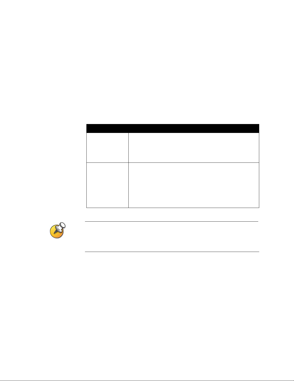
Administrator’s Guide for ViewStation EX, ViewStation FX, and VS4000
Configuring a VCR to Record Calls
You can connect a VCR or DVD to play recorded material during a call or to record
your videoconference. You can also connect two VCRs to play material and record
the conference at the same time.
No system configuration is required before playing a VCR into a call.
To configure call recording with a VCR:
1. Go to System Info > Admin Setup > Video/Cameras > VCR.
2. Configure these settings:
Setting Description
VCR Record
Source
VCR Audio Out
Always On
For information about connecting a VCR to play or record, please refer to Optional
Equipment Setup for VCR on page 2-23.
The VCR inputs are active when you select camera 3.
•Auto — Automatically records the current speaker.
•Near — Records the near site video only.
•Far — Records the far site video only.
Note: Audio from all sites is always recorded.
Species how the audio output behaves.
When this setting is disabled, the system supplies audio to the
VCR audio outputs only when the system is receiving audio from
the far site.
If you use a VCR to record the conference, enable this setting so
that the audio from the near-site microphone pods and data
collaboration control are recorded along with the far-site audio.
4-10 www.polycom.com/videodocumentation
Page 89
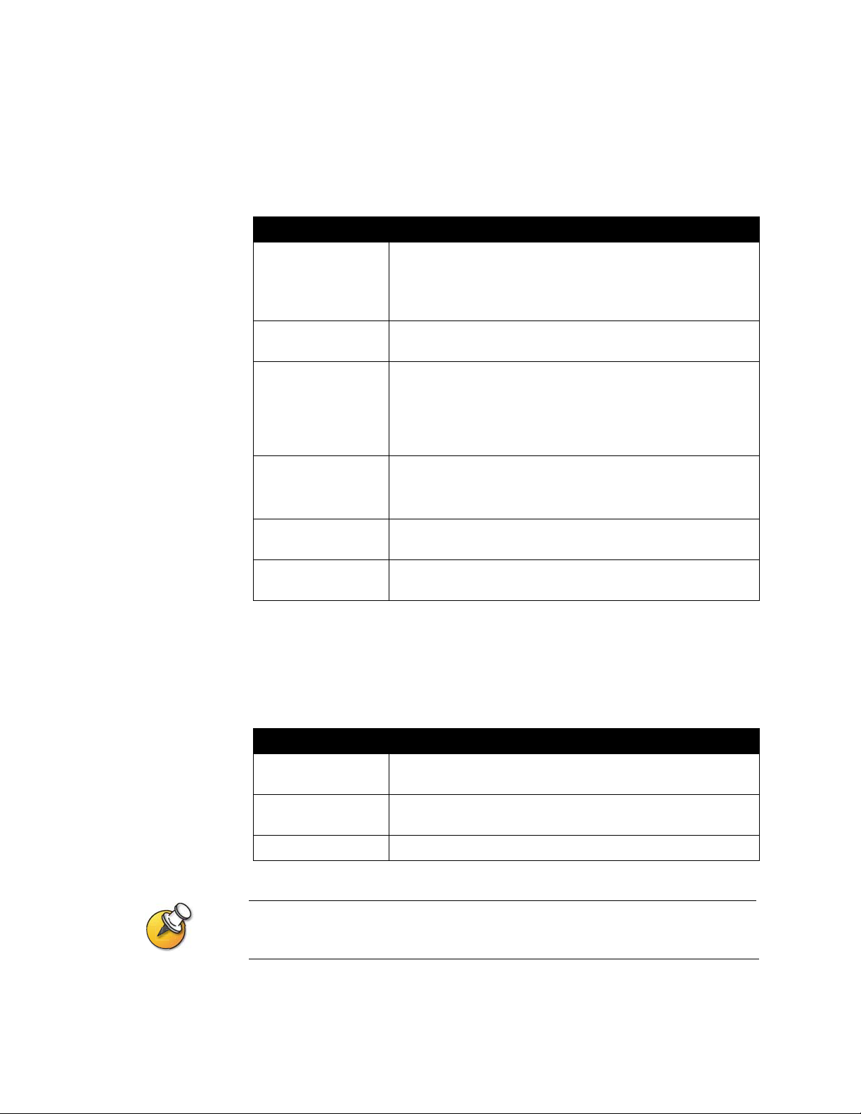
Configuring Telephone and Audio Settings
1. Go to System Info > Admin Setup > Phone/Audio.
2. Configure these settings:
Setting Description
Chapter 4 - Designing the User Experience
System Telephone
Number
Room Phone
Number
Echo Canceller Lets you specify whether to use the system’s built-in echo
Mute Auto-Answer
Calls
Sound Effects
Volume
Audio Quality Specifies the audio quality preference depending on call
Specifies the phone number of the system, including country
and area codes for the system’s location.
If you do not select System Telephone Number, the Telephone
selection is not available from the main screen.
Enter the telephone number of the room where the system is
located.
canceller.
Note: If you are using a Polycom Vortex® system with your
ViewStation system, and you want to use to the Polycom V ortex
echo cancellation feature, clear this selection.
Selects whether to mute incoming calls.
Incoming calls are muted by default until you press the mute
button on the microphone pod or the remote control.
Sets the volume level of the ring tone and user alert tones.
bandwidth.
Configuring for Use with a Touch Panel Control
1. Go to System Info > Admin Setup > Software/Hardware > RS-232.
2. Configure these settings:
Setting Description
Baud Rate Set the baud rate to the same value that it is set on the touch
panel control.
RS-232 Mode Select Control. This allows any device connected to the RS-232
port to control the system.
Flow Control Set this to match the touch panel control.
For a list of all available API commands, see the API Guide for ViewStation EX,
ViewStation FX, and VS4000, available at www.polycom.com/videodocumentation.
© Polycom, Inc. 4-11
Page 90

Administrator’s Guide for ViewStation EX, ViewStation FX, and VS4000
Displaying Closed Captions
You can provide real-time text transcriptions or language translations of the video
conference by displaying closed captions on your system. When you provide
captions for a conference, the captioner uses a web browser to listen to the
conference audio and enter the caption text in the system’s web interface. When
the captioner sends a unit of text, all sites see it on the main monitor for 15 seconds.
The text then disappears automatically.
Closed captions are supported for IP or ISDN point-to-point calls between these
systems:
❑ ViewStation SP, MP, V.35/RS-449/RS-530 systems with software version 6.5 or
later
❑ ViewStation FX or VS4000 with software version 2.5 or later
To supply closed captions for a conference:
1. On a PC, open a web browser.
2. In the browser address line, enter the IP address of the system, for example,
http://255.255.255.255, to go to the system’s web interface.
3. Click Show Closed Caption.
4. Log in using this information:
User Name: Your na me.
Password: Meeting password defined for your video conferencing system.
5. In the Closed Captioning screen, type the caption text into the Current field.
You can enter up to 250 characters per line.
6. Press Enter to send the text to the sites in the conference.
The text is also added to the History field of the Closed Captioning screen.
4-12 www.polycom.com/videodocumentation
Page 91

Chapter 4 - Designing the User Experience
Configuring Data Conferences and Streaming Calls
Configuring Data Conferences
ViewStation systems support data conferencing for:
❑ point-to-point ISDN calls, and
❑ multipoint calls using external H.320 bridges that support this feature.
You can configure your ViewStation system to work with other data conferencing
devices, such as ShowStation, WebStation, and StreamStation. You can also
configure the ViewStation system to work with Microsoft NetMeeting.
To configure a data conference:
1. Go to System Info > Admin Setup > Data Conference.
2. Enter the IP address of the data conferencing device, or the IP address of the
PC on which NetMeeting is running.
For detailed instructions on setting up NetMeeting for calls, please refer to the Getting
Started Guide for ViewStation EX, FX, and VS4000.
Configuring and Starting Streaming Calls
You can stream audio and video from one to many viewers with your ViewStation
system, both in and out of a call. Viewers watch your presentation or meeting, via
the system’s web interface, from their PC.
To configure a stream:
1. Go to System Info > Admin Setup > LAN/H.323 > Streaming.
2. Configure these settings:
Setting Description
Speed Specifies the speed used for the streaming call.
IP Multicast Address Specifies the multicast address used for the stream. The default
address is based on your system serial number but can be
changed, if required.
© Polycom, Inc. 4-13
Page 92

Administrator’s Guide for ViewStation EX, ViewStation FX, and VS4000
Setting Description
Number of Router
Hops
Audio Port Specifies the fixed port used for audio. This can be changed if
Video Port Specifies the fixed port used for video. This can be changed if
Allow Streaming Adds the Call Type icon to the main screen.
Enable Streaming
Announcement
Restore Defaults Restores to original settings.
Specifies the number of routers the data can traverse before it is
no longer passed on. For example, when set to 1, the data stays
within a subnet.
you need to go through a firewall.
you need to go through a firewall.
By selecting Call Type > Streaming Call from the main scre en,
users can start streaming calls.
Specifies whether the names of users logged on to the
streaming system are displayed on screen.
To stream a conference:
1. On the main screen, select Call Type > Streaming Call.
2. Enter the password users must enter to view the streamed call from a browser.
Give this password to users who need to access the stream.
3. Select Start to begin streaming.
4. Place the video call to other participants.
You can also start streaming after you place the call.
To stop streaming a conference:
1. Press Call • Hang Up on the remote control.
2. Select Call Type.
3. Select Stop Streaming.
4-14 www.polycom.com/videodocumentation
Page 93

Chapter 4 - Designing the User Experience
To stream a conference using the web interface:
1. On a PC, open a web browser.
2. In the browser address line, enter the system’s IP address, for example,
http://255.255.255.255, to go to the system’s web interface.
3. Enter admin as the user name, and the admin password, if a password has
been established.
4. Go to Set Up System > Admin Setup > LAN, H.323 and Global Services >
Streaming.
5. Click Click here to go to Start Streaming page.
6. Click Start Stream.
To view a streamed conference:
1. On a PC, open a web browser.
2. In the browser address line, enter the system’s IP address, for example,
http://255.255.255.255, to go to the system’s web interface.
3. Click View a Meeting.
4. Log in using this information:
• User name: Your name
• Password: Password defined for the streamed conference. For more
information, contact the person who initiated the call.
5. Click View Streaming Video.
Instructions for viewing streams are also available in the Getting Started Guide for
ViewStation EX, ViewStation FX, and VS4000.
© Polycom, Inc. 4-15
Page 94

Administrator’s Guide for ViewStation EX, ViewStation FX, and VS4000
Designing General System Behaviors
You can configure the following general system behaviors to accommodate the
needs of your organization.
❑ General Setup
❑ Multipoint Calling
❑ Call Answer Mode
❑ Passwords and Security Options
❑ Date, Time, and System Location
For information about... See...
Setting video network
usage preferences for
calls
Setting call speeds for
users
Configuring General Setup
The General Setup screen provides access to high-level options for the entire
system. For convenience, some of the User Setup options are repeated on these
screens.
1. Go to System Info > Admin Setup > General Setup.
2. Configure these settings:
Setting Description
Language Sets the language for the user interface.
Country Specifies the country where the system is located.
System Name Enter or change the system name in this field. This name appears
Configuring Video Call Preferences on page 3-4.
Configuring Dialing Speeds on page 3-10.
Changing the country automatically adjusts the country code
associated with your system number .
on the screen for the far site when you are making calls.
Auto-Answer Point
to Point
Auto-Answer
Multipoint
4-16 www.polycom.com/videodocumentation
Specifies whether to answer incoming point-to-point calls
automatically.
Specifies whether to accept incoming multipoint calls
automatically.
Page 95

Chapter 4 - Designing the User Experience
Setting Description
Allow Dialing Specifies whether to allow users to place calls to destinations
other than those listed in the Address Book.
Display My IP or
ISDN Information
Maximum Time in
Call
Specifies whether to display the system’s IP address, ISDN
number, or both on the main screen.
Enter the maximum number of minutes allowed for call length.
When that time has expired, you see a message asking you if you
want to hang up or stay in the call. If you do not answer within one
minute, the call automatically disconnects. If you choose to stay
in the call at this time, you will not be prompted again.
3. Select and configure these settings:
Setting Description
Allow User Setup Specifies whether the User Setup scre e n is accessible to users
via the System Info screen.
Uncheck this option if you do not want users to change
environmental settings.
Allow Address Book
Changes
Keypad Audio
Confirmation
Display Speed Dial Specifies whether to display the Speed Dial list via the Address
Allow Modifications
to Camera Presets
Specifies whether users can save changes they make to the
system’s local address book.
Specifies whether to play a voice confirmation of numbers
selected with the remote control.
Book option.
Specifies whether to allow users to set or change camera preset
positions.
Screen Saver Wait
Time
© Polycom, Inc. 4-17
Specifies how long the system remains awake during periods of
inactivity.
Page 96
Administrator’s Guide for ViewStation EX, ViewStation FX, and VS4000
Configuring Multipoint Calling
You can use the ViewStation systems to participate in multipoint conferences.
Multipoint conferences include multiple video sites (IP and ISDN) and can also
include voice-only calls. During a multipoint conference, a multipoint
conferencing unit (MCU) enables the video to switch to the various sites so that
you can see and hear the other conference participants.
You can use the internal MCU or the Conference-on-Demand feature of Polycom’s
PathNavigator for multipoint calling.
The ViewStation FX and VS4000 are automatically enabled for multipoint calling.
If you are using a ViewStation EX, you need to enter a multipoint option key to
enable multipoint calling.
Entering a multipoint software registration key (ViewStation EX only)
Before placing multipoint calls with your ViewStation EX, you must enter a
multipoint software registration key.
1. Go to System Info > Admin Settings > Software/Hardware > System
Options.
2. Enter the multipoint key provided.
For information about purchasing the multipoint call option, please contact your Polycom
distributor.
4-18 www.polycom.com/videodocumentation
Page 97
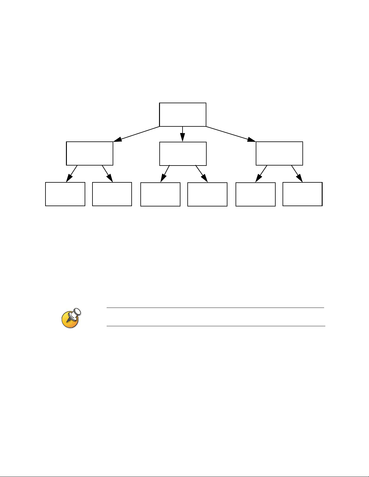
Including more than three other sites in a cascaded call
You can include up to ten sites in a call if the sites you call have the internal MCU
capability. The diagram below shows how to do this.
Originating system (site 1)
ViewStation EX,
ViewStation FX,
or VS4000
Chapter 4 - Designing the User Experience
Site
Any videoconferencing
system
ViewStation EX,
ViewStation FX,
2
or VS4000
Site
5
4
Site
9
ViewStation EX,
ViewStation FX,
or VS4000
Any videoconferencing
system
Any videoconferencing
system
Site
6
Site
Any videoconferencing
system
ViewStation EX,
ViewStation FX,
3
or VS4000
Site
7
Any videoconferencing
system
Site
8
Site
Any videoconferencing
system
To place a cascaded call:
1. In the Address Book, create and call a multi-site entry, or place calls to up to
three other sites.
2. Ask each far site to call up to two additional sites. Along with these two sites,
each far site in the original multipoint call can add an audio-only site.
Calls through PathNavigator cannot be cascaded.
Site
10
© Polycom, Inc. 4-19
Page 98

Administrator’s Guide for ViewStation EX, ViewStation FX, and VS4000
Configuring multipoint settings
You can customize the way video is handled in multipoint calls to best support the
types of calls your organization is making.
To configure multipoint video:
1. Go to System Info > Admin Setup > Video Network > Multipoint Setup.
2. Configure these settings:
Setting Description
Multipoint Mode •Auto — The view switches between Full Screen mode and
Discussion mode, depending on the interaction between the
sites.
If multiple sites are talking at the same time, Discussion mode
is used. If one site is talking uninterrupted for at least 15
seconds, the speaker appears full screen.
•Discussion — All sites are displayed at the same time in
separate windows on the display. This mode is also called
continuous presence.
• Presentation — The speaker sees all other sites in discussion
mode while the other sites see the speaker in full screen mode.
•Full Screen — The site that is speaking is shown in full screen
to all other sites. This mode is also called voice-activated
switching.
Auto-Answer
Multipoint
Specifies whether to accept incoming multipoint calls
automatically.
4-20 www.polycom.com/videodocumentation
Page 99

Chapter 4 - Designing the User Experience
Configuring with PathNavigator’s Conference on Demand feature
If your organization uses Polycom’s PathNavigator, you can use PathNavigator’s
Conference on Demand feature to place multipoint calls with up to 10 sites,
including the site that places the call.
In order to place calls using PathNavigator, you need to:
❑ register your ViewStation system with PathNavigator,
❑ configure your ViewStation system to use PathNavigator for multipoint calls
(see Configuring the System to Use a Gatekeeper on page 3-10), and
❑ create a multi-site entry in the Address Book that can be used to place the
multipoint call.
Things to note when using PathNavigator’s Conference on Demand:
❑ Once the call begins, users cannot add another site to the call — even if the site
was in the call originally and is attempting to rejoin. Because of this, you
cannot place cascaded multipoint calls through PathNavigator.
❑ The MGC needs to have enough ports available to complete the call. The
system displays a message if the MGC does not have enough ports available
to connect all the sites.
Setting the Call Answering Mode
You can set up the system to answer calls automatically or manually or to refuse
incoming calls.
To set the call answer mode:
1. Go to System Info > Admin Setup > General Setup.
2. Select Auto-Answer Point to Point to set the answer mode for calls with one
site, or select Auto-Answer Multipoint to set the mode for calls with two or
more other sites.
3. Choose from the following:
•Yes — To answer calls automatically
•No — To answer calls manually
• Do Not Disturb — To refuse incoming calls automatically. The caller
receives a message that the site is unavailable.
© Polycom, Inc. 4-21
Page 100

Administrator’s Guide for ViewStation EX, ViewStation FX, and VS4000
Configuring AES Encryption
Before you can make encrypted calls, you may be required to enter an AES
encryption software registration key.
1. Go to System Info > Admin Setup > Software/Hardware > System Options.
2. Enter the AES encryption key provided.
3. Go to System Info > Admin Setup > Security.
4. Under Encryption, configure these settings:
Setting Description
Required Specifies that all calls must be encrypted. If the far site does not
support encryption, calls will not be connected.
Disabled Specifies that the encryption option is not required for calls.
When available Specifies that encryption will be used when it is available on far
site systems, however unencrypted calls will still be connected
successfully.
For information about purchasing the AES encryption option, please contact your Polycom
distributor.
4-22 www.polycom.com/videodocumentation
 Loading...