

Page 1

ViewStation® EX User
Guide
VS4000 User’s Guide
March 2003 Edition
March 2003 Edition
MarchMarch
3725-21086-001A
3725-21086-001A
Page 2

Trademark Information
e
Polycom®, the Polycom logo design, and ViewStation® are registered trademarks of Polycom Inc. ARENA™, Global
Management System™, PathNavigator™, Polycom OneDial™, and Visual Concert™ are trademarks of Polycom,
Inc. in the United States and various other countries.
Internet Explorer™, NetMeeting®, Windows®, and Windows NT® are either registered trademarks or trademarks of
Microsoft Corporation in the United States and/or other countries.
Intel®, Pentium®, and Celeron® are registered trademarks and TeamStation™ is a trademark of Intel Corporation.
Adobe® Acrobat® is a registered trademark of Adobe Systems Incorporated.
ADTRAN® is a registered trademark of ADTRAN, Inc.
QuickTime™ is a trademark of Apple Computer, Inc.
Netscape® Navigator® is a registered trademark of Netscape Communications Corporation.
IP/TV® is a registered trademark of Cisco Systems, Inc.
All other trademarks are the property of their respective owners. Every effort has been made to ensure that the
information in this manual is accurate. Polycom, Inc. is not responsible for printing or clerical errors. Information in
this document is subject to change without notice.
Patent Information
The accompanying product is protected by one or more U.S. and foreign patents and patents pending held by
Polycom, Inc.
© 2003 Polycom, Inc. All rights reserved.
Polycom Inc.
4750 Willow Road
Pleasanton, CA 94588-2708
USA
No part of this document may be reproduced or transmitted in any form or by any means, electronic or mechanical,
for any purpose, without the express written permission of Polycom, Inc. Under the law, reproducing includes
translating into another language or format.
As between the parties, Polycom, Inc. retains title to, and ownership of, all proprietary rights with respect to the
software contained within its products. The software is protected by United States copyright laws and international
treaty provision. Therefore, you must treat the software like any other copyrighted material (e.g. a book or sound
recording).
Every effort has been made to ensure that the information in this manual is accurate. Polycom, Inc. is not responsibl
for printing or clerical errors. Information in this document is subject to change without notice.
Page 3

Chapter 1 - Welcome to the ViewStation EX
Feature Highlights .....................................................................................................18
What is in the Box? ....................................................................................................20
ViewStation EX ....................................................................................................20
Network Interface Module.................................................................................20
Additional Information.......................................................................................21
Remote Control.............................................................................................21
Microphone Pod ...........................................................................................21
Power Supply................................................................................................22
Help and Technical Support .....................................................................................23
Using Help............................................................................................................23
Help Topics...........................................................................................................24
Troubleshooting...................................................................................................24
General...........................................................................................................24
Audio..............................................................................................................26
Video ..............................................................................................................27
How to Contact Technical Support...................................................................27
By Phone ........................................................................................................27
By Internet .....................................................................................................28
Contents
Chapter 2 - Installing the ViewStation EX
What you Need to Install the ViewStation EX System..........................................30
Television Monitors.............................................................................................30
Network Interfaces ..............................................................................................30
Ethernet..........................................................................................................30
ISDN ...............................................................................................................30
Power Source........................................................................................................31
Integrated Cameras .............................................................................................32
Sony EVI-10 Camera ....................................................................................32
NT-1 Device..........................................................................................................32
Required Information..........................................................................................33
Equipment Installation...............................................................................................33
Setting up the ViewStation EX...........................................................................34
ISDN Network Interface Modules ....................................................................35
Setting up the V.35/RS-449/RS-530 Network Interface.........................35
Setting up the Quad BRI Network Interface.............................................38
© Polycom, Inc. 2003 i
Page 4

ViewStation EX User Guide
Optional Equipment ...........................................................................................41
Second Monitor ............................................................................................41
VCR ................................................................................................................41
Document Camera ....................................................................................... 41
Visual Concert DC .......................................................................................42
Visual Concert FX......................................................................................... 42
ShowStation IP.............................................................................................. 43
Upgrading Software ..................................................................................................45
Upgrading Software over IP..............................................................................45
Upgrading Software over ISDN (H.320)..........................................................47
Updating System Software From a PC on a LAN...................................48
Updating System Software Directly From a PC ...................................... 49
Updating a System Already Loaded With the Current System Software52
Updating System Software Remotely ....................................................... 54
Upgrading the System for Multipoint Calls...........................................................55
Chapter 3 - Initial System Setup
First System Screens .................................................................................................. 59
Selecting the Language....................................................................................... 59
Selecting Menu Items with the Remote Control.............................................60
Setting up System Name and Country............................................................. 61
System Name ................................................................................................61
Country.......................................................................................................... 62
Setting your Call Preference ..............................................................................62
Initial Setup for IP (H.323) Calls .............................................................................. 64
Setup for IP (H.323) Calls................................................................................... 64
Setting up a Gatekeeper .....................................................................................66
Initial Setup for ISDN (H.320) Calls ........................................................................ 67
Setup for the V.35/RS-449/RS-530 Network Interface..................................67
Setting Video Network Options................................................................. 68
Selecting Dialing Speeds .............................................................................69
Setting Broadcast Mode Options ............................................................... 69
Setting Advanced Dialing Preferences......................................................70
Entering V.35/RS-449/RS-530 Video Numbers ...................................... 72
Setup for the Quad BRI Network Interface ..................................................... 73
Entering ISDN Video Numbers .................................................................73
Entering Service Profile Ids Manually ...................................................... 74
Selecting the ISDN Switch Protocol...........................................................75
Final Out-of-Box System Setup Screens .................................................................76
Configuring for Outside Line Calls ..................................................................76
Adding a Telephone Number............................................................................77
Setting the Administrator Password ................................................................77
ii www.polycom.com
Page 5

Setting up the Firewall ...............................................................................................79
Verifying Initial Setup ...............................................................................................80
Placing a Test Call................................................................................................80
Checking the Network Connectivity Indicators on the Main Screen...........80
Network Line Check Indicators .................................................................81
ISDN Line Check Indicators .......................................................................81
Gatekeeper Status Indicators ......................................................................82
Chapter 4 - Advanced Configuration for your Network
Environment
Configuration of the LAN Settings .........................................................................85
Configuring LAN and Intranet Settings...........................................................85
Selecting Advanced LAN Settings ....................................................................89
Configuring Firewall and LAN Connection Settings ....................................91
Configuration for IP (H.323) Calls ...........................................................................93
Configuring H.323 Name and Extension .........................................................94
Selecting Dialing Speeds.....................................................................................95
Configuring the Gateway and Gatekeeper......................................................96
Overview .......................................................................................................96
About Polycom OneDial..............................................................................97
Setting the Gateway and Gatekeeper ........................................................98
Configuring the Gateway Number............................................................100
Selecting your Gateway Prefix and Suffix ................................................101
Configuration for ISDN (H.320) Calls .....................................................................103
Advanced V.35/RS-449/RS-530 Network Interface Configuration.............103
Configuring the V.35/RS-449/RS-530 Serial Interface Control Signals104
Setting up Satellite (H.331) Broadcast Mode............................................105
Selecting Dialing Speeds..............................................................................106
Setting the Calling Profile............................................................................108
Enabling Crypto Resync..............................................................................110
Advanced Quad BRI Network Interface Configuration ...............................111
Entering ISDN Video Numbers..................................................................112
Entering or Detecting Service Profile Ids..................................................113
Setting Audio Quality Preference ..............................................................114
Setting Channel Dialing Preferences .........................................................116
Selecting Dialing Speeds..............................................................................116
Modifying ISDN Video Network Information.........................................117
Configuration of the Global Address Book ...........................................................119
Overview...............................................................................................................119
About the Global Address Book........................................................................120
Configuring Settings for the Global Address Book Server............................120
Setting the Global Address Book Preferences .................................................121
Contents
© Polycom, Inc. 2003 iii
Page 6

ViewStation EX User Guide
Selecting your Preferred Alias...........................................................................123
Selecting the Call Type Order for OneDial Address Book Entries ..............124
Entering the Private Network Number............................................................125
Establishing Dialing Rules .................................................................................125
Dialing Rules 1.............................................................................................. 125
Dialing Rules 2.............................................................................................. 128
Configuration for the Global Management System ..............................................130
Overview ..............................................................................................................130
About Global Management System.................................................................. 130
Setting Global Management Preferences.........................................................132
Accessing Global Management Server URLs..................................................133
Adding Global Management Technical Support Contact Information....... 134
Configuring Streaming Preferences ........................................................................ 136
Configuring SNMP Preferences ...............................................................................138
Configuring Quality of Service ...............................................................................140
Chapter 5 - Using the ViewStation EX
Remote Control...........................................................................................................144
Video Calls ..................................................................................................................148
Placing a Call Manually...................................................................................... 148
Using One Number......................................................................................148
Using Two Numbers....................................................................................151
Placing a Call from the Address Book..............................................................153
Placing a Speed-Dial Call ...................................................................................154
Placing a Call from the Web Interface..............................................................155
Placing a Call Using the Application Programming Interface .....................155
Answering a Video Call Manually ................................................................... 155
Answering a Video Call Automatically...........................................................156
Setting the System to Do Not Disturb..............................................................156
Ending a Video Call ............................................................................................157
Analog Telephone Calls ............................................................................................ 158
Placing a Telephone Call....................................................................................158
Adding a Telephone Call to a Video Call........................................................159
Disconnecting a Telephone Call........................................................................ 159
Adding a Video Call to a Telephone Call........................................................160
Address Book ............................................................................................................. 161
Adding an Entry to the Address Book.............................................................162
Editing an Existing Entry in the Address Book..............................................163
Deleting Entries in the Address Book ..............................................................164
Transferring the Address Book ......................................................................... 164
Using the Global Address Book........................................................................ 165
Creating Multipoint Address Book Entries..................................................... 166
iv www.polycom.com
Page 7

Contents
Cameras and Sound ...................................................................................................167
Controlling Cameras ...........................................................................................167
Selecting a Near-Site Camera......................................................................167
Selecting a Far-Site Camera.........................................................................168
Controlling the Near-Site Camera..............................................................168
Controlling the Far-Site Camera.................................................................169
Adjusting Camera Settings..........................................................................170
Setting Camera Presets ................................................................................170
Enabling Automatic Voice Tracking..........................................................171
Enabling Automatic Tracking to Camera Presets....................................172
Controlling Sound ...............................................................................................173
Setting the Volume.......................................................................................173
Using the Mute Button.................................................................................173
Controlling Sound Effects Volume ............................................................174
Snapshots ....................................................................................................................175
Sending Snapshots...............................................................................................175
Snapshot Timeout................................................................................................175
Picture-In-Picture (PIP) .............................................................................................177
Graphics Cursor .........................................................................................................178
General Information............................................................................................178
Using the Graphics Cursor.................................................................................179
Chapter 6 - Using Advanced System Features
Multipoint Calls (Optional).......................................................................................182
Before you Begin..................................................................................................182
Multipoint Dialing Speed Table .................................................................182
Mixed Protocol Dialing Speed Table .........................................................183
Multipoint Downspeeding..........................................................................184
Multipoint Calls and Firewall Information ..............................................185
Placing Multipoint Video Calls..........................................................................186
Using the Manual Dialer (Video Phone)...................................................186
Using an Address Book Meeting Entry.....................................................188
Using the Address Book..............................................................................190
Using the Manual Dialer and the Address Book.....................................190
Mixed Protocol Dialing.......................................................................................191
Different Ways to Place a Mixed Protocol Call........................................191
Additional Information ...............................................................................192
Multipoint Viewing Modes................................................................................193
Mode Description.........................................................................................194
Switching Modes ..........................................................................................196
Multipoint Conference Password......................................................................196
Setting Up the Meeting Password..............................................................197
© Polycom, Inc. 2003 v
Page 8

ViewStation EX User Guide
Using the Meeting Password......................................................................197
MCU Meeting Password Protection in Multipoint Dial-In Calls.......... 198
Multipoint Cascading Capabilities ...................................................................200
Chair Control ....................................................................................................... 201
General Information ....................................................................................201
Actions Available to All Sites..................................................................... 202
Actions Only Available to the Chair Controller......................................203
Dial-In Calling (Optional) ........................................................................................204
Dial-In Calling Scenarios....................................................................................204
With an Existing Point-to-Point Call.........................................................204
With no Existing Point-to-Point Call......................................................... 205
Auto Answer Multipoint Mode Configuration ..............................................206
Setting the Auto Answer Multipoint Mode.............................................206
Streaming Video ........................................................................................................ 208
Enabling Streaming.............................................................................................208
Configuring Streaming Options........................................................................ 209
Configuring Streaming for Apple QuickTime................................................210
Enabling and Starting Streaming on the ViewStation EX...................... 210
Viewing Streaming with Apple QuickTime on the PC ..........................210
Data Conferencing ..................................................................................................... 212
Enabling Data Conferencing on your System.......................................... 213
Using a ShowStation IP...............................................................................213
Using Microsoft NetMeeting......................................................................213
Chapter 7 - Using the System with a PC
Before you Begin......................................................................................................... 216
PC Requirements................................................................................................. 216
Connecting the PC and the ViewStation EX to the LAN...............................216
Connecting the PC Directly to a ViewStation EX not on the LAN .............. 219
Configuring your Web Browser........................................................................ 221
Internet Explorer Configuration ................................................................221
Netscape Configuration ..............................................................................222
Accessing the Web Interface .................................................................................... 224
Basic Features of the Web Interface ........................................................................225
Placing a Call........................................................................................................225
Placing a Call from the Address Book ...................................................... 227
Placing a Call from the Global Address Book.......................................... 227
Placing a Call Using the Manual Dialer....................................................227
Loading and Selecting a Slide Presentation.....................................................228
Loading a Slide Presentation on the PC....................................................229
Selecting a Slide Presentation on the ViewStation EX............................ 232
Slide Display Information...........................................................................234
vi www.polycom.com
Page 9

Viewing a Slide Presentation .............................................................................234
Viewing a Meeting...............................................................................................236
Advanced Features of the Web Interface ...............................................................237
Closed Caption.....................................................................................................237
Accessing and Using Closed Caption........................................................237
Additional Information About Closed Caption.......................................238
PolycomSnap........................................................................................................239
Address Book Utility...........................................................................................240
NetMeeting ...........................................................................................................241
Enabling NetMeeting on the ViewStation EX ..........................................242
Accessing NetMeeting .................................................................................242
Information About Placing an IP Video Calls with NetMeeting...........243
System Setup and Remote Management ................................................................245
Admin Setup/General Setup.............................................................................246
System Diagnostics..............................................................................................247
System Diagnostics.......................................................................................248
Virtual Remote Control ...............................................................................248
Send a Message.............................................................................................249
Streaming ....................................................................................................................250
Chapter 8 - Troubleshooting
Contents
General .........................................................................................................................252
Audio ...........................................................................................................................253
Video ............................................................................................................................255
Network and Communications ...............................................................................257
IMUX ............................................................................................................................259
LAN/Intranet .............................................................................................................260
Presentations ...............................................................................................................261
Remote Control ..........................................................................................................263
Appendix A - Screen Reference
System Information Reference..................................................................................266
Diagnostics Screen Reference ...................................................................................268
Network Statistics................................................................................................268
Advanced Network Statistics.............................................................................269
About Polycom Video Error Concealment™ (PVEC).............................270
Call Status .............................................................................................................271
Color Bars..............................................................................................................271
Audio.....................................................................................................................272
Generate Tone ...............................................................................................272
© Polycom, Inc. 2003 vii
Page 10

ViewStation EX User Guide
Audio Meter..................................................................................................273
Near End Loop.....................................................................................................273
Far End Loop........................................................................................................274
Reset System.........................................................................................................274
User Setup Screen Reference ....................................................................................275
Admin Setup Screen Reference ...............................................................................279
General Setup....................................................................................................... 280
V.35/RS-449/RS-530 Video Network Screens................................................282
Multipoint Setup .......................................................................................... 282
Call Preference..............................................................................................283
Video Network .............................................................................................283
Dialing Speeds..............................................................................................283
Broadcast Mode............................................................................................283
Advanced Dialing ........................................................................................ 283
Video Numbers ............................................................................................ 283
Advanced V.35..............................................................................................284
BRI Video Network Screens...............................................................................284
IMUX (Inverse Multiplexer)....................................................................... 284
ISDN Video Numbers.................................................................................. 284
Auto Detect SPIDs........................................................................................284
Audio Quality............................................................................................... 284
Advanced Dialing ........................................................................................ 284
Dialing Speeds..............................................................................................285
Call Preference..............................................................................................285
Multipoint Setup .......................................................................................... 285
ISDN Video Network ..................................................................................285
LAN Setup Screens.............................................................................................. 285
LAN & Intranet (main)................................................................................ 285
LAN & Intranet (Configuration)................................................................ 285
Advanced LAN Settings .............................................................................286
Firewall & LAN Connection....................................................................... 286
H.323 Setup (main).......................................................................................286
H.323 Setup (configuration)........................................................................286
Dialing Speeds..............................................................................................286
Gateway & Gatekeeper................................................................................ 286
Gateway Number.........................................................................................286
Gateway Setup.............................................................................................. 286
Streaming.......................................................................................................287
SNMP Setup..................................................................................................287
Global Address (Main)................................................................................287
Global Address (Server)..............................................................................287
Global Address Book Preferences..............................................................287
Preferred Alias..............................................................................................287
Advanced Address Book Preferences.......................................................287
viii www.polycom.com
Page 11

Contents
Private Network ISDN Number.................................................................288
Dialing Rules 1..............................................................................................288
Dialing Rules 2..............................................................................................288
Global Management (Main)........................................................................288
Global Management (Configuration) ........................................................288
Global Management URLs..........................................................................288
Global Management Info.............................................................................288
Quality of Service .........................................................................................288
Data Conference...................................................................................................289
Telephone & Audio .............................................................................................291
Video and Cameras Screens...............................................................................292
Monitors.........................................................................................................292
TV Monitors...................................................................................................293
Graphics Monitor..........................................................................................294
EX VGA Monitor ..........................................................................................295
Cameras..........................................................................................................295
VCR Setup......................................................................................................297
VGA Input Calibration ................................................................................298
Security..................................................................................................................299
Crypto Resync Pulse............................................................................................300
Software and Hardware Screens .......................................................................300
Software .........................................................................................................300
RS-232.............................................................................................................301
Hardware Information.................................................................................301
Send Address Book ......................................................................................302
Far Site Software Update.............................................................................302
System Options.............................................................................................302
Appendix B - Interoperability Information
H.320 Endpoint Interoperability...............................................................................306
H.323 Endpoint Interoperability...............................................................................307
MCU H.320 Interoperability......................................................................................308
MCU H.323 Interoperability......................................................................................308
Gateway/Gatekeeper/T120 Server Interoperability .............................................309
Firewall/NAT Interoperability.................................................................................310
Appendix C - ViewStation EX Technical Specifications
ViewStation EX Technical Specifications ................................................................311
© Polycom, Inc. 2003 ix
Page 12

ViewStation EX User Guide
x www.polycom.com
Page 13

List of Figures
Figure 1-1.Help Screen (Main)............................................................................................. 23
Figure 1-2.Help Screen (Topics) .......................................................................................... 24
Figure 2-1.ViewStation EX with Sony EVI-10 Camera .................................................... 32
Figure 2-2.V.35/RS-449/RS-530 Network Interface Module (P-LINK side) ................ 36
Figure 2-3.V.35/RS-449/RS-530 Network Interface Module (NETWORK side)......... 37
Figure 2-4.Quad BRI Network Interface Module (P-LINK side).................................... 39
Figure 2-5.Quad BRI Network Interface Module (Network side).................................. 40
Figure 2-6.Softupdate Screen............................................................................................... 46
Figure 2-7.Softupdate System Info Screen......................................................................... 47
Figure 3-1.Welcome (Language) Screen............................................................................. 59
Figure 3-2.How to Select Menu Items Screen.................................................................... 60
Figure 3-3.System Name Screen.......................................................................................... 61
Figure 3-4.Country Screen.................................................................................................... 62
Figure 3-5.Call Preference Screens...................................................................................... 63
Figure 3-6.H.323 Setup Screen............................................................................................. 64
Figure 3-7.Gatekeeper Screen .............................................................................................. 66
Figure 3-8.Video Network Screen....................................................................................... 68
Figure 3-9.Dialing Speeds Screen........................................................................................ 69
Figure 3-10.Advanced Dialing Screen................................................................................ 70
Figure 3-11.Advanced Dialing Screen (Calling Profile List) ........................................... 71
Figure 3-12.Video Numbers Screen.................................................................................... 72
Figure 3-13.ISDN Video Numbers Screen ......................................................................... 74
Figure 3-14.Auto Detect SPIDs Screen ............................................................................... 74
Figure 3-15.ISDN Switch Protocol Screen.......................................................................... 75
Figure 3-16.Outside Line Calls Screen................................................................................ 76
Figure 3-17.Telephone Numbers Screen............................................................................ 77
Figure 3-18.Administrator Password Screen..................................................................... 78
Figure 3-19.ViewStation EX Main Screen .......................................................................... 81
Figure 3-20.Main Screen (showing network conditions)................................................. 82
Figure 4-1.LAN & Intranet Screen ...................................................................................... 86
Figure 4-2.Advanced LAN Settings Screen ....................................................................... 89
Figure 4-3.Firewall & LAN Connection Screen................................................................. 91
Figure 4-4.H.323 Setup Screen (configuration) ................................................................. 94
Figure 4-5.Dialing Speeds Screen........................................................................................ 95
Figure 4-6.Gateway & Gatekeeper Screen ......................................................................... 98
Figure 4-7.Gateway Number Screen................................................................................. 100
Figure 4-8.Gateway Screen................................................................................................. 101
Figure 4-9.Advanced V.35 Screen ..................................................................................... 104
© Polycom, Inc. 2003 xi
Page 14

ViewStation EX User Guide
Figure 4-10.Video Network Screen and Broadcast Mode Screens................................106
Figure 4-11.Dialing Speeds Screen ....................................................................................107
Figure 4-12.Advanced Dialing Screen (Page 1) ...............................................................109
Figure 4-13.Advanced Dialing Screen (Calling Profile List)..........................................109
Figure 4-14.Crypto Resync Pulse Screen ..........................................................................110
Figure 4-15.ISDN Video Numbers Screen........................................................................112
Figure 4-16.Auto Detect SPIDs Screen..............................................................................113
Figure 4-17.Audio Quality Preference Screen..................................................................115
Figure 4-18.Advanced Dialing Screen...............................................................................116
Figure 4-19.Dialing Speeds Screen ....................................................................................117
Figure 4-20.Global Address (Server) Screen ....................................................................121
Figure 4-21.Global Address Book Preferences Screen (for IP and ISDN Calls)..........122
Figure 4-22.Dialing Rules 1 Screen....................................................................................127
Figure 4-23.Dialing Rules 2 Screen....................................................................................128
Figure 4-24.Global Management (Setup) Screen.............................................................132
Figure 4-25.Global Management URLs Screen................................................................134
Figure 4-26.Global Management Info Screen...................................................................135
Figure 4-27.Streaming Screen.............................................................................................136
Figure 4-28.SNMP Setup Screen ........................................................................................138
Figure 4-29.Quality of Service Screen ...............................................................................140
Figure 5-1.Remote Control..................................................................................................145
Figure 5-2.Video Phone Screen ..........................................................................................148
Figure 5-3.Call Progress Indicators ...................................................................................150
Figure 5-4.Call Hangup Choices Screen ...........................................................................150
Figure 5-5.Address Book Screen........................................................................................153
Figure 5-6.Speed Dial Screen..............................................................................................154
Figure 5-7.Telephone Screen ..............................................................................................158
Figure 5-8.Address Book Screen........................................................................................161
Figure 5-9.Add/Change Entry Screen..............................................................................162
Figure 5-10.............................................................................................................................167
Figure 5-11.Camera Control Button on Remote Control................................................169
Figure 6-1.Cascading 10 Sites in a Multipoint Call .........................................................200
Figure 6-2.Chair Control Screen.........................................................................................202
Figure 6-3.Streaming Screen...............................................................................................208
Figure 6-4.Data Conference Screen....................................................................................212
Figure 7-1.LAN & Intranet Screen.....................................................................................217
Figure 7-2.Placing a Video Call Web Screen....................................................................226
Figure 7-3.Select a Presentation for Viewing Web Screen .............................................229
Figure 7-4.pcPresent Screen................................................................................................230
Figure 7-5.pcPresent: File Open Screen ............................................................................231
Figure 7-6.Available Presentations Screen .......................................................................232
Figure 7-7.Presentation Password Screen.........................................................................232
Figure 7-8.Presentation Directory (showing Loaded Slides) Screen ............................233
Figure 7-9.View a Meeting Web Screen ...........................................................................236
xii www.polycom.com
Page 15

Figure 7-10.PolycomSnap Interface .................................................................................. 239
Figure 7-11.Address Book Utility Screen......................................................................... 240
Figure 7-12.General Setup Web Screen ............................................................................ 246
Figure 7-13.System Diagnostics Web Screen................................................................... 248
Figure 7-14.Streaming Web Screen................................................................................... 250
Figure A-1.User Setup Screen............................................................................................ 275
Figure A-2.Admin Setup Screen........................................................................................ 279
Figure A-3.General Setup Screen ...................................................................................... 280
Figure A-4.Data Conference Screen.................................................................................. 289
Figure A-5.Telephone & Audio Screen ............................................................................ 291
Figure A-6.Graphics Monitor Screen................................................................................ 294
Figure A-7.VCR Setup Screen............................................................................................ 297
Figure A-8.VGA Input Calibration Screen....................................................................... 298
© Polycom, Inc. 2003 xiii
Page 16

ViewStation EX User Guide
xiv www.polycom.com
Page 17

List of Tables
Table 1-1.Key features of the ViewStation EX system ..................................................... 18
Table 4-1.Dialing rules used by the Global Address Book............................................ 126
Table 5-1.Remote Control Functionality .......................................................................... 145
Table 5-2.Graphic cursor function and remote control.................................................. 179
Table 6-1.Multipoint Dialing Speeds................................................................................ 183
Table 6-2.Mixed Protocol Dialing Speeds........................................................................ 184
Table 6-3.Firewall TCP/UDP Ports in Multipoint Calls................................................ 186
Table 6-4.MCU Meeting Password Protection................................................................ 198
Table 6-5.Dial-In Calling with an Existing Point-to-Point Call..................................... 205
Table 6-6.Dial-In Calling with no Existing Point-to-Point Call .................................... 205
Table B-1.H.320 Endpoint Interoperability...................................................................... 306
Table B-2H.323 Endpoint Interoperability....................................................................... 307
Table B-3.MCU H.320 Interoperability............................................................................. 308
Table B-4.MCU H.323 Interoperability............................................................................. 308
Table B-5.Gateway/Gatekeeper/T120 Server Interoperability.................................... 309
Table B-6.Firewall/NAT Interoperability........................................................................ 310
Table C-1.ViewStation EX Technical Specifications....................................................... 311
© Polycom, Inc. 2003 xv
Page 18

ViewStation EX User Guide
xvi www.polycom.com
Page 19
1
Welcome to the ViewStation EX
The ViewStation EX system is an easy-to-use, yet powerful set-top,
network appliance that provides the clearest audio and video in the
videoconferencing industry. The ViewStation EX system is a
mid-range conference room product that was designed to deliver
quality video and audio communications to mid-size conference
rooms, boardrooms, classrooms and custom conferencing facilities.
Note
Throughout this manual, the word “system” refers to the ViewStation
EX system.
Topics in This Chapter
The following topics are included in this chapter.
Topic Description Page
Feature
Highlights
What is in the
Box?
Help and
Te c hn i c a l
Support
© Polycom, Inc. 2003 17
This is an overview of the ViewStation EX
system’s main features and benefits.
This section lists the contents of the
ViewStation EX shipping container.
This section describes how to use the
system Help screen and how to contact
Technical Support.
18
20
23
Page 20

ViewStation EX User Guide
Feature Highlights
The following table provides a summary of the ViewStation EX
system’s main features and benefits. Refer also to the ViewStation
EX Technical Specifications in Appendix D for additional
information.
Table 1-1. Key features of the ViewStation EX system
Feature Description
Video The ViewStation EX system delivers TV quality
Audio The system provides clear 360 degree, full-duplex,
video for lifelike conferencing interaction while fully
supporting the H.263 video standard and the new 60
fields/ second ITU standard.
digital audio with noise suppression, switchable
echo cancellation and automatic gain control, as well
as customized audio—extended audio flexibility via
dual microphone pods and line-level audio input for
custom microphones/mixers.
Camera Support Supports a pan-tilt-zoom camera, a VCR and
document camera input, including support for the
Visual Concert™ DC.
Network Flexibility The system supports the Quad BRI,
V.35/RS-449/RS-530, and Ethernet network
interfaces up to 768 Kbps.
Multipoint
Videoconferencing
Mixed Protocol Dialing Mixed Protocol Dialing enables up to four sites over
Dial-In Calling While in a video call, other endpoints (IP, ISDN, or
18 www.polycom.com
The ViewStation EX can be upgraded using a
special key to support MultiPoint Plus as an option.
The system contains an embedded four-port MCU
for easy, on-demand, multipoint conferencing.
Up to four sites can participate (over IP and ISDN in
the same call) at 128 Kbps for ISDN and 256 Kbps
for IP for a continuous presence, voice activated, or
a chair control call using the one-button address
book dialing.
IP and ISDN in the same call.
POTS) can dial into the call or easily be added by a
call from the host.
Page 21

Chapter 1 - Welcome to the ViewStation EX
Table 1-1. Key features of the ViewStation EX system
Cascading The Cascading feature allows you to add more video
and audio participants to a multipoint video call,
without the need for a bridge. Each of the
second-level system in a four-site multipoint
videoconference can call up two more video and one
audio site. Up to ten total video sites and four total
audio sites can participate in the call using the
built-in MCU.
Two-Monitor Support Two-monitor support allows to simultaneously
display full-screen video from up to four endpoints,
plus PC content on a separate SGA projector.
High-resolution Graphics The system supports high-resolution XGA live
graphics with Visual Concert ™ FX.
Streaming The streaming feature allows the system to multicast
the videoconference to viewers over IP.
Public and Private Networks The system supports both public and private
networks through ISDN BRI, V.35/RS-449/RS-530,
and Ethernet networks.
Web Management With embedded Web capabilities and remote
management, IT managers can perform diagnostics
and software upgrades.
Dual 10/100 Mbps Ethernet
Ports
Through the dual 10/100 Mbps Ethernet por t you can
make IP calls, connect PCs, and allow Global
Management System™ access and management.
© Polycom, Inc. 2003 19
Page 22

ViewStation EX User Guide
What is in the Box?
The following section describes the contents of the ViewStation EX
shipping container.
ViewStation EX
The following items are included in the ViewStation EX box:
❑ ViewStation EX unit
❑ Documentation
• Read Me First
• ViewStation EX QuickStart
• Documentation CD
❑ 1 microphone pod
❑ 1 power supply and cord
❑ 1 remote control
❑ Cable kit with:
• 1 RJ-9 microphone cords (brown)
• 1 S-video/triple RCA monitor cable (yellow, white, and
red)
• 1 RJ-45 keyed cable for connection to the network interface
module (light blue)
• 1 RJ-45 cable for connection to the LAN (orange)
• 1 DB-9 serial port cable for connection to a touch panel
Network Interface Module
The system may also include one of the following network interface
equipment(s) (as specified by the user):
20 www.polycom.com
Page 23

❑ V.35/RS-449/RS-530 network interface:
• V.35/RS-449/RS-530 module
❑ Quad BRI network interface:
• Quad BRI Inverse Multiplexer (IMUX)
• 4 RJ-45 cables
• 1 RJ-45 cable with a keyed connector
Additional Information
The following provides important information about essential
components of the system: the remote control, the microphone
pods, and the power supply.
Remote Control
The remote control is an integral part of the system. You can use the
remote control to configure and operate your system. Once you
have the system set up and running, press the yellow INFO button
on the remote control for a basic description of the remote control
buttons.
Chapter 1 - Welcome to the ViewStation EX
For more information about the remote control, refer to Remote
Control on page 144.
Microphone Pod
The microphone pod provides digital audio input to the system.
The microphone pod has an audio range of approximately 30 feet
(9-meters) and provides automatic gain control, noise suppression,
and echo cancellation. You can press the MUTE button on the
microphone to silence your end of the call. When the MUTE button
is lighted, your end of the call is muted.
An optional microphone pod provides enhanced audio pickup.
Your system supports a maximum of two microphone pods
daisy-chained together.
© Polycom, Inc. 2003 21
Page 24

ViewStation EX User Guide
Power Supply
To connect the microphone pods to the system:
1. Connect the 30-foot (9-meter) cable to the system and one of the
microphones pods.
2. Connect the 10-foot (3-meter) cable between the two
microphone pods.
Note
Connecting and disconnecting the microphones does not require a
reboot of the system.
The ViewStation EX system has an external power supply. It
supports line voltages between 100V and 240V and line frequencies
from 47 Hz to 63 Hz.
Note
You void the warranty and may possibly damage your system if
you do not use the provided power supply.
22 www.polycom.com
Page 25
Help and Technical Support
This section provides information about using the on-screen help,
basic troubleshooting, and contacting Polycom Technical support
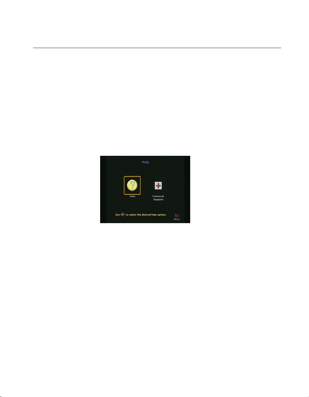
Using Help
To access the Help screen:
Press the INFO button on the remote control. If your system is
registered with a Global Management System, the following Help
screen appears.
Chapter 1 - Welcome to the ViewStation EX
Figure 1-1. Help Screen (Main)
© Polycom, Inc. 2003 23
Page 26
ViewStation EX User Guide
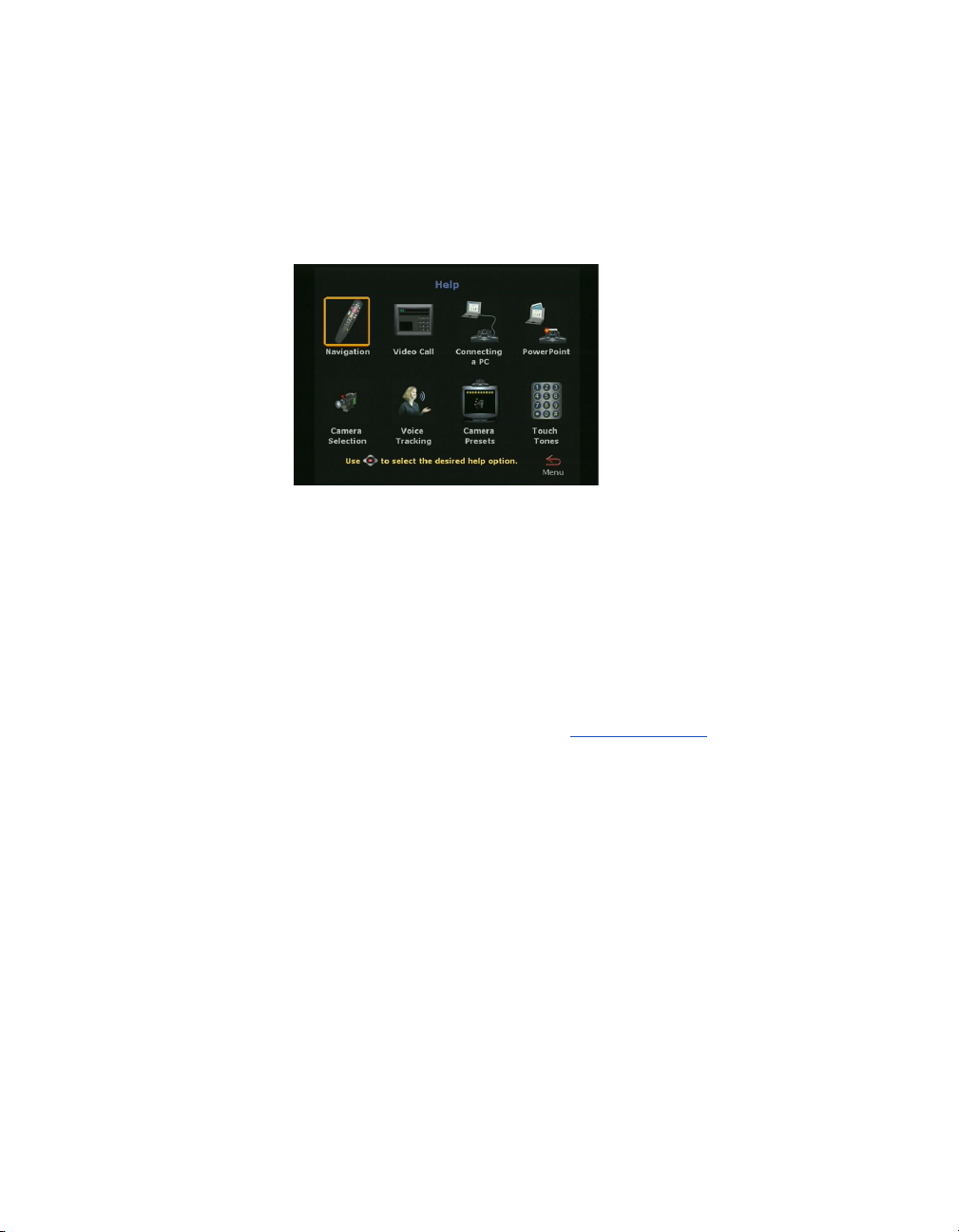
Help Topics
To access the Help screen:
Click the Help icon.
Figure 1-2. Help Screen (Topics)
Select the appropriate help topic from this screen. The topics
provide assistance with basic system usage.
Troubleshooting
This section contains basic troubleshooting information. For more
detailed information, refer to the Troubleshooting
General
Following are the most-often encountered problems and their
solutions.
Remote control is not working.
Make sure the batteries are installed. Make sure you are pointing the
remote control at the system’s IR detector. If battery power is low, a
low battery icon appears on the main screen.
24 www.polycom.com
chapter.
Page 27

Chapter 1 - Welcome to the ViewStation EX
Software Update appears when you power on the ViewStation
EX system.
The system software is corrupt or not loaded properly. Load system
software on the system from your PC. For instructions on how to do
this, refer to Upgrading Software
equipment provider.
A lightning bolt indicator appears on the left side of your far or
near-site screen.
The lightning bolt is only a visual indicator that informs you about
WAN or LAN network problems. It does not indicate performance
problems with your system.
If you are in an H.320 call, the lightning bolt most likely indicates
that the telephone company is experiencing bit errors on the line.
Contact and inform your telephone company of the existing
problem.
If you are in an H.323 call, the lightning bolt may signify that your
LAN network is experiencing packet loss, accompanied by video
and audio degradation. Contact your network manager.
, or consult your network
The lightning bolt works differently in H.320 and H.323 calls for
software version 2.5 and above:
❑ In H.320 calls, the lightning bolt appears if there are 3 or more
CRC (Cyclic Redundancy Check) errors within a period of one
second, or if there are 10 or more FEC (Forward Error
Correction) errors in a period of one second.
❑ In H.323 calls, the lightning bolt appears if more than 100 audio
and video packets are lost. The display counter is reset each time
the lightning bolt appears.
The lightning bolt is triggered when your system detects a certain
level of packet loss on the network. The frequency of the packet loss
rate can be adjusted using the remote control shell (either via RS-232
or via Ethernet/Telnet). .Refer to the ViewStat ion EX, ViewStation
FX, and VS4000 ARENA API Programmer’s Guide.
© Polycom, Inc. 2003 25
Page 28

ViewStation EX User Guide
Audio
Following are the most-often encountered audio problems and their
solutions.
No audio in a call.
❑ The system is connected to the wrong audio input on the
monitor. Make sure the monitor cables are connected as shown
in the QuickStart color cable diagrams.
❑ Far site is muted. If the far site is muted, a far site Mute icon
appears in the lower left corner of the monitor. Ask the far site
to press the MUTE button on the remote control to check if it is
muted or is not connected properly.
❑ Use the Generate Tone test on the ViewStation EX system to
help diagnose the problem.
❑ Make sure that the microphone pod is positioned correctly for
the meeting configuration. If the microphone pod is behind the
meeting participants, you may not be able to hear them speak.
For the best audio, always position the microphone pod
between the monitor and the person closest to the monitor. As
most people face the monitor during a call, following this rule
ensures that the meeting participants are also facing the
microphone pod.
You can also daisy-chain microphone pods along the conference
table. Additional microphone pods can be purchased from the
Polycom Web store. Follow the same rule for multiple
microphone pods and do not position the pods behind the
meeting participants.
You hear echoes when speaking.
Echoes are always caused by the far site in a call. Have the far site
turn down the volume and make sure that their microphones are
placed away from the system and monitor speakers.
Not enough volume in a call.
The volume is set too low on either the system or the television
monitor. For best results, set the volume on the television monitor to
26 www.polycom.com
Page 29

Video
Chapter 1 - Welcome to the ViewStation EX
one-half its maximum volume and set the volume on the system to
a comfortable level.
Following are the most-often encountered video problems and their
solutions.
No picture on the main monitor.
The system enters sleep mode after 3 minutes of inactivity. In sleep
mode, the system appears to be powered off. To “wake up” the
system, pick up the remote control, or press the button on the front
of the system.
Same picture on first and second monitors.
❑ You pressed the SNAPSHOT button. The second monitor is
previewing the video on the primary monitor for the snapshot.
Press SNAPSHOT to send a snapshot and then press
SNAPSHOT again to return to live video.
❑ You may have connected your second composite monitor to the
VCR out port on the back of the system.
How to Contact Technical Support
By Phone
Before calling Polycom technical support, have the following
information ready:
❑ Description of the issue
❑ The ViewStation’s 14-digit serial number on the label located on
the bottom of the unit.
Contact Polycom Technical Support at 1-800-POLYCOM. Listen for
the product support prompt.
© Polycom, Inc. 2003 27
Page 30

ViewStation EX User Guide
By Internet
To contact Polycom technical support, go to the Polycom Global
Services Web page at http://esupport1.polycom.com/cgi/top.asp.
This page allows you to enter your contact information as well as a
question or a description of the problem. Including the following
information will decrease the amount of time needed to assess your
situation:
❑ The ViewStation’s 14-digit serial number on the label located on
the bottom of the unit.
❑ Software revision of the product
❑ Network information
❑ Troubleshooting steps you tried to implement
Response time to technical support inquiries will not exceed two
business days. Response time on basic or technical information
requests about Polycom products and their capabilities may vary
with the complexity of the question.
28 www.polycom.com
Page 31

2
Installing the ViewStation EX
This chapter provides all of the instructions you need to install the
ViewStation EX system successfully. It also covers the optional
network interface installation if you are using ISDN for your video
calls.
You should read this chapter in conjunction with the QuickStart
card. This card was shipped in the system box.
Topics in This Chapter
The following topics are included in this chapter.
Top ic Description Page
What you Need
to Install the
ViewStation EX
System
Equipment
Installation
Upgrading
Software
Upgrading the
System for
Multipoint Calls
© Polycom, Inc. 2003 29
This section lists the additional items that
you need to install your ViewStation EX
system.
This section gives step-by-step
instructions needed to install the system
and, if applicable, the appropriate network
interface.
This section describes how to update
software over an IP or ISDN network.
This section describes how to add the
multipoint key to enable multipoint calling
on the ViewStation EX system.
30
33
45
55
Page 32

ViewStation EX User Guide
What you Need to Install the ViewStation EX System
This section lists the additional items you need to install the
ViewStation EX system. It also provides a checklist of information
you should have on hand during the installation process.
For details about the system components, see the QuickStart card
provided with each system.
Television Monitors
You can use the ViewStation EX with two television monitors and a
VGA monitor that operates at 75 Hz or higher with a resolution of
800 x 600, 1024 x 768, or 1280 x 1024.
The ViewStation EX system can use any S-video or composite
television monitor as the primary monitor. The other monitor has to
be S-video.
The size of the monitor should be proportional to the size of the
room where video conferences take place.
Network Interfaces
Ethernet
A Local Area Network (LAN) Ethernet connection is needed if you
plan to use IP.
ISDN
If you are using one of the following ISDN network interfaces with
your system, you will need the appropriate network equipment and
access to services for the specified network interface:
30 www.polycom.com
Page 33

Chapter 2 - Installing the ViewStation EX
❑ V.35/RS-449/RS-530 network interface:
• V.35/RS-449/RS-530 module
• Optional cables used to connect the V.35/RS-449/RS-530
module to the DCE:
– (V.35 “Y” cable (HD-44M to DB-25M/RS-366 and M34
“Winchester” V.35 )
– RS-449/422 “Y” cable (HD-44M to DB-25M/RS-366 and
DB-37M/RS-449/422)
– Ascend cable (HD-44M to HD-44M)
Note
These cables are available from the Polycom Web store.
• Access to your Data Communications Equipment (DCE) or
Data Service Unit (DSU).
❑ Quad BRI network interface:
• Quad BRI Inverse Multiplexer (IMUX)
• 4 RJ-45 cables
– 1 RJ-45 cable with a keyed connector
– BRI line ordered from your service provider
Power Source
The ViewStation EX system has an external power supply. It
supports line voltages between 100V and 240V and line frequencies
from 47 Hz to 63 Hz.
Warning
You void the warranty and may possibly damage your system if
you do not use the provided power supply.
© Polycom, Inc. 2003 31
Page 34

ViewStation EX User Guide
Integrated Cameras
Sony EVI-10 Camera
The ViewStation EX system supports the Sony EVI-10 camera. This
camera has a built-in wide-angle lens and has a new form factor.
Figure 2-1. ViewStation EX with Sony EVI-10 Camera
Caution
Attaching a third-party vendor wide-angle lens will cause damage
that is not covered by your product warranty. Third-party lenses
will rub against the system’s enclosure when the camera is reset.
Note
The camera is controlled with the remote control that is shipped
with the system. Manually adjusting the camera can damage the
unit.
NT-1 Device
An ISDN network termination (NT-1) device may be required
between your ISDN line and the system. If your system is not
connected to an internal switchboard, such as a PBX, it may require
an ISDN termination resistor to be installed.
32 www.polycom.com
Page 35

Required Information
Before you start installing the equipment, obtain the following
information:
❑ IP address of the ViewStation EX system: to be provided by
your Internet Service Provider or system administrator.
❑ ISDN numbers: to be provided by your Network Service
Provider.
❑ SPIDs: to be provided by your Network Service Provider.
❑ Switch protocols: to be provided by your Network Service
Provider.
❑ Gatekeeper address: to be provided by your Network Service
Provider or system administrator.
❑ Firewall information: to be provided by your Network Service
Provider or system administrator.
❑ Telephone numbers: to be provided by your system
administrator.
Chapter 2 - Installing the ViewStation EX
Equipment Installation
This section describes how to set up the following equipment:
❑ ViewStation EX. See Setting up the ViewStation EX.
❑ Network interface modules (V.35/RS-449/RS-530, and BRI).
See ISDN Network Interface Modules
© Polycom, Inc. 2003 33
.
Page 36

ViewStation EX User Guide
Setting up the ViewStation EX
To connect your cables and equipment to the back of the
ViewStation EX system:
1. Place the system on top of the television monitor with the front
lip overhanging the top of the television monitor.
2. Place the microphone pod on a flat surface between the meeting
participants and the television monitors. Do not place the
microphone pod near the television monitor speakers.
Connecting and disconnecting the microphone off the system does
not require a reboot of the system.
3. Connect the required equipment and cables to the back of your
system as shown in the QuickStart.
Note
4. Connect any optional equipment to the back of your system as
shown in the QuickStart. Optional equipment can include a PC,
VCR, telephone, audio mixer, document camera, XGA projector
or monitor, Visual Concert FX, or additional television
monitors.
Note
The colors on the cables match the colors on the back of the
system panel.
5. To prevent cable entanglement, wrap the enclosed cable tie
around all of the cables.
6. Put the batteries in the remote control.
You are now ready to set up your network interface. See ISDN
Network Interface Modules, on page 35 for additional information.
34 www.polycom.com
Page 37

ISDN Network Interface Modules
This section explains how to install the following ISDN network
interfaces:
❑ V.35/RS-449/RS-530. See Setting up the V.35/RS-449/RS-530
Network Interface on page 35.
❑ BRI. See Setting up the Quad BRI Network Interface on page 38.
Setting up the V.35/RS-449/RS-530 Network Interface
This section explains how to install and connect the
V.35/RS-449/RS-530 network interface module so that you can
make calls over ISDN with the system.
The V.35/RS-449/RS-530 network interface supports the V.35,
RS-449, or RS-530 protocol depending on the cable you use to
connect your equipment.
Chapter 2 - Installing the ViewStation EX
Connecting a V.35/RS-449/RS-530 network interface module to
your system:
1. Make sure your system is turned off.
2. Insert one end of the light blue keyed cable into the light blue
port on the back of the system. The cable has special RJ-45
connectors that are not interchangeable with normal RJ-45
connectors.
3. Insert the other end of the light blue RJ-45 cable into the input
port labeled xon the network interface module.
© Polycom, Inc. 2003 35
Page 38

ViewStation EX User Guide
Figure 2-2 shows the peripheral link (P-LINK) side of the network
interface module that connects to the EX system.
12 VDC Connector
(not used)
Port (not used)
Input Port
LEDs
Figure 2-2. V.35/RS-449/RS-530 Network Interface Module (P-LINK side)
To connect the V.35/RS-449/RS-530 network interface module
to the DCE:
The V.35/RS-449/RS-530 network interface module contains two
HD-44 female ports (labeled 1 and 2) that connect to the data
communications equipment (DCE).
1. Connect the HD-44 male cable ends to ports 1 and 2 on the
network interface module. If you want to connect only one
cable, connect to port 1 on the interface module.
2. Tighten the screws on the connectors.
3. Connect the remaining cable ends to the DCE's
V.35/RS-449/RS-530 port and the DB-25 RS-366 dialing port, if
used. If you are connecting only one cable, connect to the lowest
ordered port on your DCE.
4. Tighten the screws on the connectors.
5. Power on the television monitor.
6. Power on the system. Once you power up the system, there is a
20-second delay before you see the Polycom logo.
7. Once your interface is properly connected, you are ready to
configure your system. Proceed to chapter 3.
36 www.polycom.com
Page 39

Chapter 2 - Installing the ViewStation EX
Figure 2-3 shows the network side of the network interface module
that connects to the DCE.
LEDs
Figure 2-3. V.35/RS-449/RS-530 Network Interface Module (NETWORK
side)
Special Information
V.35/RS-449/RS-530 Module Interchangeability. This system only
operates with the V.35 module that is compatible with the
ViewStation FX. It is not compatible with the V.35 module that
operates with the ViewStation H.323 system. The new module uses
HD-44F connectors (ports 1 and 2), and uses a keyed RJ-45 connector
for the serial link to the back panel of the ViewStation EX system. An
HD-44M to DB-25F adapter cable is available as an option to connect
existing V.35/RS-449/RS-530 network cables, if necessary.
Cable Information. The following optional cables used to connect
the V.35/RS-449/RS-530 module to the DCE are available from the
Polycom Web store:
❑ V.35 “Y” cable—HD-44M to DB-25M/RS-366 and M34
“Winchester” V.35
❑ RS-449/422 “Y” cable—HD-44M to DB-25M/RS-366 and
DB-37M/RS-449/422
❑ Ascend cable—HD-44M to HD-44M
Cable drawings and pinout information is available in the “V.35
Technical Information” section of the Integrators’ Reference Manual
for ViewStation EX, ViewStation FX, and VS4000.
© Polycom, Inc. 2003 37
Page 40

ViewStation EX User Guide
V.35/RS-449/RS-530 Cable Adapter Kit. You can also purchase an
additional cable adapter kit (available through your reseller) to
extend the distance between your system and the
V.35/RS-449/RS-530 network interface module.
V.35/RS-44/RS-530 and RS-366 Connections. The
V.35/RS-449/RS-530 connection on the V.35 cable is used for data
and the RS-366 connection is used for dialing. If you plan to place 2
x 56 Kbps or 2 x 64 Kbps calls, use one cable for each port.
Note
If your DCE does not use dialing, do not use the RS-366 (DB-25M)
connector.
LED Information. Refer to the V.35/RS-449/RS-530 Technical
Information section of the Integrators’ Reference Manual for
ViewStation EX, ViewStation FX, and VS4000.
Setting up the Quad BRI Network Interface
This section explains how to install and connect the Quad BRI
network interface module so that you can make calls over ISDN
with the ViewStation EX system.
To connect the Quad BRI network interface module to the
system:
1. Make sure your system is turned off.
2. Find the cable with the light blue RJ-45 keyed connector on one
end and the green RJ-45 (non-keyed) connector on the other
end.
3. Insert the light blue RJ-45 keyed connector into the light blue
RJ-45 keyed port on the back of the system.
4. Insert the green (non-keyed) RJ-45 connector into the green
RJ-45 port labeled xon the network interface module.
38 www.polycom.com
Page 41

Chapter 2 - Installing the ViewStation EX
Figure 2-4 shows the peripheral link (P-LINK) side of the Quad BRI
network interface module that connects to the ViewStation EX
system.
Figure 2-4. Quad BRI Network Interface Module (P-LINK side)
To connect the Quad BRI network interface module to the BRI
network:
1. Attach your RJ-45 network cable(s) from port 1 on your ISDN
BRI network to the connector labeled ISDN S/T on the Quad
BRI network interface module.
2. Power on the television monitor.
3. Power on the system. Once you power up the system, there is a
20-second delay before you see the Polycom logo.
4. Once your interface is properly connected, you are ready to
configure your system. Proceed to chapter 3, Initial System
Setup.
© Polycom, Inc. 2003 39
Page 42

ViewStation EX User Guide
Figure 2-5 shows the network side of the Quad BRI network
interface module that connects to the ISDN BRI network.
Figure 2-5. Quad BRI Network Interface Module (Network side)
Special Information
Quad BRI/IMUX. The Quad BRI is also called IMUX (for Inverse
Multiplexer). With the Quad BRI, you can connect up to four ISDN
lines to the video conferencing unit. The Quad BRI allows multi-line
ISDN connections to be “muxed” together to create a higher
bandwidth connection to the far-site device. Each ISDN line adds
128 Kbps to the possible operating line.
ISDN Lines. The system can use up to four ISDN lines. Note that the
system only require a single functioning ISDN line to operate, but
speeds greater than 128 Kbps require the use of additional ISDN
lines.
NT-1. If you are not connected to an internal phone system, called a
PBX, you will need to connect the ISDN cables from your system to
the Quad BRI module, to the network termination (NT-1) device,
which is connected to the ISDN wall jack.
For more information about ISDN, refer to the Integrators’ Reference
Manual for ViewStation EX, ViewStation FX, and VS4000.
LED Information. Refer to the BRI Technical Information section of
the Integrators’ Reference Manual for ViewStation EX, ViewStation FX,
and VS4000.
40 www.polycom.com
Page 43

Optional Equipment
You can enhance your videoconferences by using optional
equipment. Refer to the ViewStation EX QuickStart for color cable
diagrams that show how to connect optional equipment to the
system.
Second Monitor
The second monitor displays what would otherwise be displayed in
the smaller picture-in-picture window of a single-monitor system.
To install a second monitor:
1. Insert the monitor cable in the monitor 2 output jack.
2. Connect the other end to the monitor 2 output jack.
VCR
Chapter 2 - Installing the ViewStation EX
You can use a video cassette recorder (VCR) to record your
videoconference or to present recorded material as part of your
videoconference. The VCR records video from the near site’s main
television monitor and audio from both the near and far sites. When
playing tapes, the VCR provides audio and video to all participants
in a call.
1. To play a tape in the VCR, press the NEAR button on the remote
control twice.
2. Use the ARROW buttons to highlight the VCR icon on the
screen. Press the SELECT button on the remote control.
3. Use the VCR remote control to play the tape.
Document Camera
You can use a document camera to take pictures of an object or
document and send them to a far site.
© Polycom, Inc. 2003 41
Page 44

ViewStation EX User Guide
Visual Concert DC
1. To use a document camera with your system, press the NEAR
button on the remote control twice.
2. Then use the ARROW buttons to highlight the Document
Camera icon on the screen. Press the SELECT button on the
remote control.
Visual Concert™ DC is part of the Visual Concert series of
collaboration products designed to maximize video conferencing.
This is a custom-integrated document camera that has the ability to
send images at SXGA (1280 x 1024) resolution with full motion
capture during a video call. It lets you save images from the glass
onto a PCMCIA card, annotate images with a virtual drawing pen,
view transparent material using backlighting or send a
high-resolution preview with the SNAPSHOT button.
For more information about installing Visual Concert DC, consult
Visual Concert DC User Guide and Visual Concert DC QuickStart.
Visual Concert FX
The ViewStation EX system supports the use of Visual Concert™
FX. Visual Concert™ FX is a collaborative product with the
capability of transmitting a high-resolution graphics stream with
high-quality audio in any conference, including multipoint calls. It
is transmitted to the other site in a conference in tandem with your
live video stream. It works with your laptop, desktop, or Macintosh
at resolutions up to and including 1280 x 1024.
The video and graphic images can be displayed at both the near and
far ends in dual stream mode, video on one monitor and the live
graphics on a second monitor (for example, the far site can see you
and your presentation live at the same time).
The live images can be from virtually any source on the laptop or
desktop such as PowerPoint, Excel, a Web page or proprietary
software applications. Visual Concert FX is designed to transmit
graphics at SXGA resolution (1280 x 1024), but will auto-sync to
match the resolution of the laptop and scale to match the best
resolution at the far end. A VGA-out port on the unit allows the
42 www.polycom.com
Page 45

Chapter 2 - Installing the ViewStation EX
flexibility of connecting a high-resolution projection system or
monitor for in-room displays.
Dual Stream Compatibility
Visual Concert FX dual stream is compatible with the Polycom
Accord MCU version 3.01 in ISDN multipoint calls. All sites are able
to see the presenter and the PC at the same time.
Limitations
If the far site cannot support dual streams, the system reverts to
sending the live computer screen as the main video stream.
Note
For more information about installing Visual Concert FX, consult
the Visual Concert FX User Guide and Visual Concert FX QuickStart.
ShowStation IP
The ShowStation® IP allows you to project any type of document or
Microsoft Office file in big-screen format and share it with any
location instantly.
The ShowStation IP works best when you have two ViewStation EX
systems, two ShowStations with LAN cards, and an RJ-45 cable. For
information about installing ShowStation IP refer to the ShowStation
User Guide.
To connect and use the ShowStation IP:
1. Use the provided blue RJ-45 cable to connect the ShowStation
2. Find the LAN name of the ShowStation. Click the To ol ba r icon
3. Power on your system.
LAN card to the blue LAN port on the back of the system. You
can also connect the ShowStation and the system to the same
LAN.
on the main menu of the ShowStation. The Site Name is under
the Preferences tab.
© Polycom, Inc. 2003 43
Page 46

ViewStation EX User Guide
4. Select System Info>Admin Setup>Data Conference and enter
the name of the ShowStation on the Data Conference screen.
5. Place a video call between the two ViewStation EX systems.
When the systems connect, the ShowStations synchronize with
one another automatically.
Once the systems have connected, a whiteboard appears on the
ShowStations’ LCD displays. It takes approximately 30 seconds for
the whiteboard to appear once the video call is placed. You are now
ready to use your ShowStation.
44 www.polycom.com
Page 47

Upgrading Software
The Softupdate application will update all versions of ViewStation
software. To update the software, your system must be on local area
network (LAN) or directly connected to a PC via Ethernet.
Before you begin, print the Read Me First file that is provided with
the system software. It contains updated information that may not
be included in this guide.
Do not power off your system during the software update process.
If you turn off your system during the download process, your
system reverts to its original software version.
Upgrading Software over IP
Chapter 2 - Installing the ViewStation EX
Caution
You can upgrade the software on your system with the Softupdate
application available from the Software Download Center on the
Polycom Web site at www.polycom.com.
If you do not have Internet access, your reseller can supply you with
the application on CD-ROM.
To upgrade your system software over IP:
1. Double-click the software zip file and extract the files to a
directory on your PC.
2. Double-click the Softupdate.exe file to open the Softupdate
application.
© Polycom, Inc. 2003 45
Page 48

ViewStation EX User Guide
Figure 2-6. Softupdate Screen
3. Click the Softupdate button, as shown in Figure 2-6.
4. Enter the IP address of the system and the administrator
password, if required, then click OK.
5. In the System Info screen, specify whether to delete the address
book and system files during the update.
6. Determine whether you want to make your system a DHCP
server. Selecting the Allow System to be a DHCP Server option
will make the Server button visible on the LAN & Intranet
screen in the user interface (System Info>Admin
Setup>LAN/H.323>LAN/Intranet>LAN&Intranet).
Warning
Do not select the Server option if your system is on a LAN with
other computers. If you do, the system provides IP addresses to the
other computers on the LAN even though the LAN already has a
46 www.polycom.com
Page 49

Chapter 2 - Installing the ViewStation EX
DHCP server. Your system administrators may have to repair any
network problems this causes.
Figure 2-7. Softupdate System Info Screen
7. Click Continue to start the upgrade process.
8. When the upgrade has finished, click OK to close the dialog
box.
Upgrading Software over ISDN (H.320)
The software on your ViewStation EX system can be upgraded
through an ISDN (H.320) video call from any other ViewStation EX
system.
You can perform a software update to the far site over your
V.35/RS-449/RS-530, or BRI line during a call. Updating works best
at speeds of 512 Kbps and below.
To upgrade your system over ISDN:
1. Place a video call to the system you want to upgrade.
© Polycom, Inc. 2003 47
Page 50

ViewStation EX User Guide
Updating System Software From a PC on a LAN
2. Select System Info > Admin Setup > Security and write down
the passwords that appear on the Security screen of the site you
want to upgrade.
3. On the site sending the software, select System Info>Admin
Setup > Software/Hardware > Update to access the Far Site
Software Update screen.
4. Highlight the Start icon and press the SELECT button on the
remote control.
5. Enter the passwords, highlight the Start icon, and press the
SELECT button on the remote control to begin the upgrade
process.
Once the software upgrade process is complete, your system
automatically restarts.
To update your system software from a PC on the LAN:
1. Access the Sofupdate.exe file, as follows:
• From the Update CD
• From the Polycom Web site
: Insert the Update CD into your drive.
: 1. Go to the software download
center at www.polycom.com. 2. Locate your product name
and provide the required information. 3. Run the
Softupdate application to download the latest software and
update your system. Note that you need to decompress the
file before you can run the Softupdate application.
2. Double-click the Softupdate.exe icon to open the application.
3. When the application opens, click the Softupdate button.
4. Enter the IP address of your videoconferencing system in the
dialog box that appears. If the system has an administrator
password, enter it here and click OK. If it does not have a
password, leave it blank and click OK.
5. Softupdate will locate your system and provide basic
information. To retain your existing address book and files,
48 www.polycom.com
Page 51

Chapter 2 - Installing the ViewStation EX
select the appropriate options on the Softupdate screen. Then
click the Continue button.
6. As the software is being upgraded, you will be informed of its
progress. When it is finished, click the OK button. Your system
will automatically reboot.
7. If you have purchased an MP upgrade key for multipoint calls,
please refer to Upgrading the System for Multipoint Calls
page 55 for instructions on entering the key.
Updating System Software Directly From a PC
Updating your System Software to a Higher Version
To update your system software to a higher version than the one
currently on the system, follow these steps:
1. Connect one end of the blue-tipped RJ-45 cable to the blue LAN
connector on the back of your system. Connect the other end of
the blue-tipped RJ-45 cable to the Ethernet PC card of your
computer. Then turn on your system.
on
2. To connect to your desktop or laptop computer, you need to set
your system as a DHCP server. To do so, follow these
instructions:
a. Select System Info > Admin Setup > LAN/H.323 >
LAN/Intranet > LAN & Intranet.
Note
The Server button is visible on the LAN & Intranet screen only if the
option Allow System to be a DHCP Server has been previously
enabled in the System Info screen of the Softupdate application. For
more information about enabling the option Allow System to be a
DHCP Server, refer to Upgrading Software over IP.
b. In the DHCP field, select Server. The following message
will appear: “The system will now issue IP addresses to
other PCs on the LAN. Continue?”
© Polycom, Inc. 2003 49
Page 52

ViewStation EX User Guide
Caution
Do not use this setting if your system is on a LAN with other
computers. If you do, your system will provide IP addresses to the
other computers even though the LAN already has a DHCP server.
Your IT personnel and system administrators will have to repair
any network problems this causes.
c. Select Yes if you are absolutely certain you want to set your
system as a DHCP server.
d. Press Menu. The following message will appear: “Power
must be reset to save changes. Continue?” Select Yes.
e. Your system will automatically restart. It will now act as a
DHCP server and will provide IP addresses to one or more
PCs.
3. Go to the System Information screen. You should see the IP
address 1.1.1.2, which is the IP address of your system.
4. Once you get an IP address, go to your PC and follow these
instructions:
For Windows 95 and 98
:
a. Right-click the Network Neighborhood icon, and then
right-click Properties.
b. When the Network box appears, select the Configuration
tab, then double-click TCP/IP.
c. Select the IP Address tab. Make sure the Obtain an IP
Address Automatically button is selected. Then click OK.
For Windows NT 4.0
:
a. Right-click the Network Neighborhood icon, and then
right-click Properties.
b. When the Network screen appears, select the Protocols tab,
then double-click TCP/IP Protocol.
c. Select the IP Address tab. Make sure the Obtain an IP
Address Automatically button is selected. Then click OK.
50 www.polycom.com
Page 53

Chapter 2 - Installing the ViewStation EX
For Windows 2000:
a. Right-click the My Network Places icon, and then
right-click Properties.
b. In the Network and Dial-up Connections window,
right-click Local Area Connection, and select Properties.
c. In the Local Area Connection Properties window,
double-click Internet Protocol (TCP/IP).
d. In the Internet Protocol (TCP/IP) Properties window, make
sure the Obtain an IP Address Automatically button is
selected. Then click OK.
5. Restart your PC and insert the update CD into your drive. Or
access the Softupdate.exe file from the Polycom Web site
: 1. Go
to the software download center at www.polycom.com. 2.
Locate your product name and provide the required
information. 3. Run the Softupdate application to download the
latest software and update your system. Note that you need to
decompress the file before you can run the Softupdate
application.
6. Double-click the Softupdate.exe icon to open the application.
7. When the application opens, click the Softupdate button.
8. Enter the IP address of your system in the dialog box that
appears. If you have an administrative password, enter it here
and click OK. If you don’t have a password, leave it blank and
click OK.
9. Softupdate will locate your system and provide basic
configuration information. To delete your existing address book
and files, check the appropriate boxes.
10. Check the box Allow System to be a DHCP Server. Then click
the Continue button.
11. As the software is being upgraded, you will be informed of its
progress. When it is finished, click the OK button. The system
will automatically reboot. Your system software has been
loaded.
12. If you have purchased an MP upgrade key for multipoint calls,
please refer to Upgrading the System for Multipoint Calls
on
page 55 for instructions on entering the key.
© Polycom, Inc. 2003 51
Page 54

ViewStation EX User Guide
Updating a System Already Loaded With the Current System Software
To update your system software from the most-current version to
the same current version or higher, follow these steps:
1. Connect one end of the blue-tipped RJ-45 cable to the blue LAN
connector on the back of your system. Connect the other end of
the blue-tipped RJ-45 cable to the Ethernet PC card of your
computer. Then turn on the system.
2. To connect to your desktop or laptop computer, you need to set
your system as follows:
a. Select System Info > Admin Setup > LAN/H.323 >
LAN/Intranet > LAN & Intranet.
b. Press the Up arrow on the remote control to go to the DHCP
field and set it to Off.
c. In the IP Address field, enter the IP address 1.1.1.2.
d. Press Menu. The following message will appear: “Power
must be reset to save changes. Continue?” Select Yes.
e. Your system will automatically restart.
3. Go to the System Information screen. You should see the IP
address 1.1.1.2, which is the IP address of your system.
4. Go to your PC and follow these instructions:
For Windows 95/98
:
a. Right-click the Network Neighborhood icon, and then
right-click Properties.
b. When the Network box appears, select the Configuration
tab, then TCP/IP, and then select the IP Address tab. Make
sure the Specify an IP address button is selected.
c. Enter the following information:
– IP address = 1.1.1.3
– Subnet mask = 255.255.255.0
d. Then click OK.
52 www.polycom.com
Page 55

Chapter 2 - Installing the ViewStation EX
For Windows NT 4.0:
a. Right-click the Network Neighborhood icon, and then
right-click Properties.
b. When the Network screen appears, select the Protocols tab,
then double-click TCP/IP Protocol.
c. Select the IP Address tab. Make sure the Specify and IP
Address button is selected.
d. Enter the following information:
– IP address = 1.1.1.3
– Subnet mask = 255.255.255.0
e. Then click OK.
For Windows 2000
:
a. Right-click the My Network Places icon, and then
right-click Properties.
b. In the Network and Dial-up Connections window,
right-click Local Area Connection, and select Properties.
c. In the Local Area Connection Properties window,
double-click Internet Protocol (TCP/IP).
d. In the Internet Protocol (TCP/IP) Properties window, make
sure the Use the following IP address button is selected.
e. Enter the following information:
– IP address = 1.1.1.3
– Subnet mask = 255.255.255.0
f. Then click OK.
5. Restart your PC and insert the update CD into your drive.
Access the Sofupdate.exe file, as follows:
• From the Update CD:
• From the Polycom Web site
Insert the update CD into your drive.
: 1. Go to the software download
center at www.polycom.com. 2. Locate your product name
and provide the required information. 3. Run the
Softupdate application to download the latest software and
© Polycom, Inc. 2003 53
Page 56

ViewStation EX User Guide
update your system. Note that you need to decompress the
file before you can run the Softupdate application.
6. Double-click the Softupdate.exe icon to open the application.
7. When the application opens, click the Softupdate button.
8. Enter the IP address of your system in the dialog box that
appears. If you have an administrative password, enter it here
and click OK. If you don’t have a password, leave it blank and
click OK.
9. Softupdate will locate your system and provide basic
configuration information. To delete your existing address book
and files, check the appropriate boxes.
10. Click the Continue button.
11. As the software is being upgraded, you will be informed of its
progress. When it is finished, click the OK button. The system
will automatically reboot. Your system software has been
loaded.
12. If you have purchased an MP upgrade key for multipoint calls,
please refer to Upgrading the System for Multipoint Calls
on
page 55 for instructions on entering the key.
Updating System Software Remotely
Your reseller can update your system software remotely by calling
your system and downloading the new version to your system. The
process takes approximately 10 to 15 minutes in a 2 x 64 kbps call.
Follow these steps to remotely upgrade your system:
1. Contact your reseller to have the software update transmitted to
your system.
2. Give the reseller your Software Update Password and the
Admin Password (if entered) for your system. These passwords
can be found on the System Info > Admin Setup > Security
screen. They are implemented to prevent unauthorized access to
your system.
3. The reseller will place a call to your system and download the
software to your system. You will see a Remote Software
Update screen on your system. This screen will keep you
54 www.polycom.com
Page 57

Chapter 2 - Installing the ViewStation EX
informed of the progress of your update. Do not turn your
system off during this process.
Note
The software update application will terminate if there are too many
errors on the communication line. The system you are updating will
revert back to the previous software version. If your software does
not update, try using a lower data rate.
4. Once the software upgrade process completes, your system will
automatically restart and the main calling screen will appear.
5. If you have purchased an MP upgrade key for multipoint calls,
please refer to Upgrading the System for Multipoint Calls
page 55 for instructions on entering the key.
on
Upgrading the System for Multipoint Calls
If you have purchased an MP upgrade key from Polycom, you can
upgrade your ViewStation EX to support multipoint calls.
For more information about making multipoint calls, please refer to
Multipoint Calls (Optional)
To enter the MP key:
1. From the main calling screen, go to System Info>Admin
Setup>Software/Hardware>System Options.
2. Enter your multipoint key.
When MP is enabled, the Multipoint field changes from
Disabled to Enabled.
Press Select on the remote to make the keyboard appear. Your
key will be 20 characters long. Enter five characters in each box.
© Polycom, Inc. 2003 55
.
Note
Page 58

ViewStation EX User Guide
The cursor will move automatically to the next box as you add
characters. When you are finished, select Save and then Menu
to return to the main calling screen.
3. You are now ready to place a multipoint call with your
ViewStation EX system.
56 www.polycom.com
Page 59

3
Initial System Setup
This chapter describes the initial system configuration screens that
you see when you power on your ViewStation EX for the first time.
Topics in This Chapter
The following topics are included in this chapter.
Top ic Description Page
First System
Screens
Initial Setup
for IP (H.323)
Calls
Initial Setup
for ISDN
(H.320) Calls
Final
Out-of-Box
System Setup
Screens
Setting up the
Firewall
Verifying
Initial Setup
© Polycom, Inc. 2003 57
This section describes the first system
screens that are displayed during the initial
out-of-box configuration.
This section describes the initial
IP-specific screens needed to configure
basic network settings.
This sections describes the initial screens
used to configure your ISDN connection
(V.35/RS-449/RS-530 or BRI)
The screens that complete the initial
configuration sequence are covered in this
section.
This section indicates where to find the
appropriate firewall configuration
information, if you need to set up a firewall.
This section provides information about
placing a test call and checking network
connectivity.
59
64
67
76
79
80
Page 60

ViewStation EX User Guide
Once you have powered on the ViewStation EX system, a series of
setup screens appear on your television monitor, leading you
through the initial configuration process, which is described in the
following sections.
Note
All procedures detailed in these sections must be followed in order
to minimize system failures.
For the latest information about the software on your system, refer
to your system’s Read Me First and Release Notes.
58 www.polycom.com
Page 61

First System Screens
The first system screens include the following:
❑ Welcome/Language. See Selecting the Language on page 59.
❑ How to Select Menu Items. See Selecting Menu Items with the
Remote Control on page 60.
❑ System Name. See Setting up System Name and Country on
page 61.
❑ Country. See Setting up System Name and Country on page 61.
❑ Call Preference. See Setting your Call Preference on page 62.
Selecting the Language
The first setup screen to appear on your television monitor is the
Welc om e screen.
Chapter 3 - Initial System Setup
Figure 3-1. Welcome (Language) Screen
To select the language you would like to see on the
ViewStation EX system:
1. Press the arrow buttons on the remote control to highlight a
language.
© Polycom, Inc. 2003 59
Page 62

ViewStation EX User Guide
2. Then press the SELECT button on the remote control to go to the
next screen.
Note
To make selections with the remote control, aim the remote
control at the remote control IR detector or at the Clarity by
Polycom logo on the front of the system.
Selecting Menu Items with the Remote Control
The following screen explains how to select ViewStation EX items
on your television monitor. Press the SELECT button on the remote
control to proceed to the next screen.
Figure 3-2. How to Select Menu Items Screen
Tip
To return to a previous screen, press the MENU button on the
remote control or use the arrow buttons on the remote control to
highlight the Menu icon and press the SELECT button on the
remote control.
60 www.polycom.com
Page 63

Setting up System Name and Country
System Name
Use the System Name screen to name your system. Naming your
system makes it easy to find your ViewStation EX on the LAN when
it is connected.
System names can be up to 34 characters in length. The first
character has to be numeric or alphabetic, including foreign
language characters.
Chapter 3 - Initial System Setup
Figure 3-3. System Name Screen
To enter the System Name, you need to access the on-screen
keyboard.
To access the on-screen keyboard:
1. Press the SELECT button on the remote control.
2. Use the arrow buttons to move around the keyboard and press
the SELECT button to select a letter.
3. When you have finished making your entries on this screen,
review the entries for accuracy, then select the key on the
on-screen keyboard.
4. Highlight the Save icon and press the SELECT button on the
remote control to save the system name.
© Polycom, Inc. 2003 61
Page 64

ViewStation EX User Guide
Country
On the Country screen, select the country in which your system is
installed.
Figure 3-4. Country Screen
Setting your Call Preference
On the Call Preference screen, select the types of calls you can place:
❑ V.35/RS-449/RS-530 Video Calls or ISDN Video Calls:
• V.35 Video Calls—This option is available (see left picture
below) when your system is connected to a
V.35/RS-449/RS-530 network.
• ISDN Video Calls (H.320)—This option is available (see
right picture below) when your system is connected to a BRI
network.
❑ LAN/Internet Calls (H.323)—Select this option if you plan to
place IP calls.
Note
If you enable this option later (after this initial system setup),
your system resets itself automatically and takes you through
the initial setup screens described in this section. Existing
system information is not erased during this process.
62 www.polycom.com
Page 65

Chapter 3 - Initial System Setup
❑ Display IP Dialing Extension—This extension is needed when
you place a call through a Gateway. When this option is
selected, the Extension field is visible in the Video Call screen.
For more information about Gateway configuration, refer to the
section Configuring the Gateway and Gatekeeper
Figure 3-5. Call Preference Screens
When you have finished, review your selection, then highlight the
Save icon and press the SELECT button on the remote control.
on page 96.
© Polycom, Inc. 2003 63
Page 66

ViewStation EX User Guide
Initial Setup for IP (H.323) Calls
The initial IP configuration screens include the following:
❑ H.323 Setup. See Setup for IP (H.323) Calls on page 64.
❑ Gatekeeper. See Setting up a Gatekeeper on page 66.
Setup for IP (H.323) Calls
The H.323 Setup screen appears if you have previously checked the
LAN/Internet Calls (H.323) option on the previous screen (Call
Preference).
The H.323 option allows you to place video calls using IP on your
local area network (LAN) or wide area network (WAN). The H.323
Setup screen allows you to configure the H.323 name and extension
that can be used to dial your system.
Figure 3-6. H.323 Setup Screen
❑ H.323 Name when calling this system—Your system name
(previously configured in the System Name screen) is used to
initialized your H.323 name. However, you can change it on this
screen. There are no format restrictions for the H.323 name.
❑ H.323 Extension (E.164)—You can also change the extension to
a number that is easy to remember. Your administrator might
have specific names and extensions. If you have a Gatekeeper
installed on your network, other parties can call you by using
64 www.polycom.com
Page 67

Chapter 3 - Initial System Setup
the H.323 name or extension. The H.323 name and extension are
registered with your Gatekeeper. The Gatekeeper directs the
call to your system IP address.
❑ Auto H.323 Dialing—This option is enabled by default to let the
system auto-detect the type of call you are placing (IP or ISDN)
based on the video number format. If this option is enabled, the
ISDN and H.323 fields are not visible on the Video Phone
screen.
❑ Display IP Dialing Extension—This option was previously
configured in the Call Preference screen. For more information,
refer to Setting your Call Preference
Note
For additional information about H.323, see Configuration for IP
(H.323) Calls on page 93.
When you have finished, review your entries for accuracy, then
highlight the Save icon and press the SELECT button on the remote
control.
, on page 62.
© Polycom, Inc. 2003 65
Page 68

ViewStation EX User Guide
Setting up a Gatekeeper
Use the Gatekeeper screen to configure an IP (H.323) Gatekeeper.
For more detailed information about the Gatekeeper, refer to
Configuring the Gateway and Gatekeeper
Figure 3-7. Gatekeeper Screen
A Gatekeeper is not required to make an IP-to-IP LAN call. In these
situations, select the Off option.
on page 96.
Note
❑ Use Gatekeeper. This option can be set to Off, Specify, or Auto.
•Off—If you do not want to access a Gatekeeper, select this
option.
•Specify—To specify a Gatekeeper, select this option and
enter the Gatekeeper’s IP address in the Gatekeeper IP
Address field. This information is available from your
network administrator.
•Auto—To have your system automatically find an available
Gatekeeper, select the Auto option.
❑ Gatekeeper IP Address—This address is provided by your
network administrator.
When you have finished, review your entry for accuracy, then
highlight the Save icon and press the SELECT button on the remote
control.
66 www.polycom.com
Page 69

Chapter 3 - Initial System Setup
Initial Setup for ISDN (H.320) Calls
If you have an ISDN connection, you will need to configure the
appropriate interface (V.35/RS-449/RS-530, or BRI). Refer to the
appropriate ISDN network interface section:
❑ V.35/RS-449/RS-530. See Setup for the V.35/RS-449/RS-530
Network Interface on page 67.
❑ BRI. See Setup for the Quad BRI Network Interface on page 73.
Setup for the V.35/RS-449/RS-530 Network Interface
If you have a V.35/RS-449/RS-530 network interface module, the
following screens are designed to help you with your
V.35/RS-449/RS-530 network configuration:
❑ Video Network. See Setting Video Network Options on
page 68.
❑ Dialing Speeds. See Selecting Dialing Speeds on page 69.
❑ Broadcast Mode. See Setting Broadcast Mode Options on
page 69.
❑ Advanced Dialing. See Setting Advanced Dialing Preferences
on page 70.
❑ Video Numbers. See Entering V.35/RS-449/RS-530 Video
Numbers on page 72.
© Polycom, Inc. 2003 67
Page 70

ViewStation EX User Guide
Setting Video Network Options
Use the Video Network screen to set the parameters for your
V.35/RS-449/RS-530 video network.
Figure 3-8. Video Network Screen
You can set the following options on this screen:
❑ RS-366 Dialing—Enable this option if you want to call from the
system through the DCE connection to the far-end
videoconferencing system. Disable this option if you are using
your DCE to dial the call or if you have a dedicated connection
to the far site.
Note
If the RS-366 Dialing option is enabled, you need to select
Dialing Speeds on this screen (see the following Selecting
Dialing Speeds section).
❑ V.35 Ports Used—Select 1 if you are placing only 1-channel
calls. Select 1+2 if you are placing 2 x 56 Kbps or 2 x 64 Kbps
channel calls.
❑ Dialing Protocol—RS-366 appears as the dialing protocol if the
RS-366 Dialing option is enabled. If the RS-366 Dialing option
is disabled, the Dialing Protocol does not appear.
❑ Broadcast Mode—Enable or disable H.331 Broadcast Mode if
the system is connected to the network via satellite.
68 www.polycom.com
Page 71

When you have finished, highlight the Save icon and press the
SELECT button on the remote control.
Selecting Dialing Speeds
If you enabled RS-366 Dialing, select the Dialing Speeds icon in the
Video Network screen.
1. Select the dialing speeds on this screen. The default speeds are
2 x 64 Kbps, 256 Kbps, 384 Kbps, 512 Kbps, and 768 Kbps.
2. To add or remove speeds, scroll through the data rates and
press the SELECT button on the remote control to select your
preferred dialing speeds; a red check appears when a dialing
speed is selected.
Chapter 3 - Initial System Setup
Figure 3-9. Dialing Speeds Screen
Note
The selected dialing speeds apply only to RS-366 calls. Nx56 and
Nx64 are for H.320 calls, while IPx56 and IPx64 are for H.323 calls.
For non-dialed calls, the call speed is determined by the DCE.
Setting Broadcast Mode Options
If you enabled the Broadcast Mode option on the Video Network
screen, the Broadcast Mode Setup icon appears. Selecting this icon
takes you to the Broadcast Mode screen. For more information on
© Polycom, Inc. 2003 69
Page 72

ViewStation EX User Guide
Setting Advanced Dialing Preferences
the Broadcast Mode screen, refer to Setting up Satellite (H.331)
Broadcast Mode on page 105.
If you enabled RS-366 Dialing, the dialing prefixes and suffixes are
set for calls from the system on the Advanced Dialing screen.
The Advanced Dialing screen lets you select the Calling Profile
associated with dialing through a DCE.
Figure 3-10. Advanced Dialing Screen
Calling profiles for several manufacturers are included in your
system.
70 www.polycom.com
Page 73

Chapter 3 - Initial System Setup
To select and modify the calling profiles:
1. Select the Calling Profile field. The following calling profile list
appears.
Figure 3-11. Advanced Dialing Screen (Calling Profile List)
2. Select the appropriate equipment/manufacturer from the
drop-down list and press the SELECT button on the remote
control.
3. When you have finished, review your entry. The Prefix or Suffix
information (depending on the equipment name that you
selected) is now visible on the Advanced Dialing screen.
4. Highlight the Save icon and press the SELECT button on the
remote control.
Note
You have to enter the information only once on the Advanced
Dialing screen. When you place a call, there is no need to enter
the prefix again—simply select the preferred dialing speed, and
your system enters the proper prefix.
Dialing Prefix and Suffix Information. Dialing prefixes are
numbers and characters that are sent to your DCE equipment before
sending the number dialed.
Dialing suffixes define the dialing speed of the DCE equipment.
This provides the users with the ability to select the dialing speed
when placing a call.
© Polycom, Inc. 2003 71
Page 74

ViewStation EX User Guide
Entering V.35/RS-449/RS-530 Video Numbers
Prefixes and suffixes are a function of your DCE. Please consult the
DCE user guide for additional information on setting dialing
profiles.
If you enabled RS-366 Dialing, the Video Numbers screen appears.
Figure 3-12. Video Numbers Screen
To enter video numbers:
1. Enter the numbers that other sites can dial to call your system.
2. When you have finished, review your entry, then highlight the
Save icon and press the SELECT button on the remote control.
For additional information about V.35/RS-449/RS-530
configuration, see Advanced V.35/RS-449/RS-530 Network
Interface Configuration on page 103.
The initial configuration process specific to the V.35/RS-449/RS-530
network interface is complete. To continue with the initial
configuration process, skip to Final Out-of-Box System Setup
Screens on page 76.
Note
If you disabled RS-366 Dialing, you are operating in direct connect
mode and the Video Numbers screen will not be displayed.
72 www.polycom.com
Page 75

The initial configuration process specific to the V.35/RS-449/RS-530
network interface is complete. To continue with the initial
configuration process, skip to Final Out-of-Box System Setup
Screens on page 76.
Setup for the Quad BRI Network Interface
If you have a Quad BRI network interface connected to your system,
the following initial BRI configuration screens are displayed:
❑ ISDN Video Numbers. See Entering ISDN Video Numbers on
page 73.
❑ Auto Detect SPIDs. See Entering Service Profile Ids Manually
on page 74.
❑ ISDN Switch Protocol. See Selecting the ISDN Switch Protocol
on page 75.
Chapter 3 - Initial System Setup
Entering ISDN Video Numbers
On the ISDN Video Numbers screen, enter the area code or the STD
code and ISDN number assigned to your system. Your service
provider should have given you this number when you purchased
your ISDN line.
© Polycom, Inc. 2003 73
Page 76
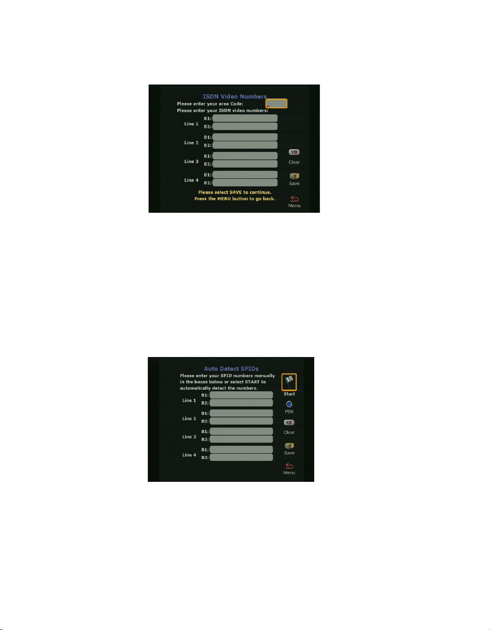
ViewStation EX User Guide
Entering Service Profile Ids Manually
When you are finished, highlight the Save icon and press the
SELECT button on the remote control.
Figure 3-13. ISDN Video Numbers Screen
On the Auto-Detect SPIDs screen, enter the Service Profile ID
numbers for your system. If you are connected to an internal phone
system (PBX), you may not need to enter SPIDs.
If the system is unable to find your SPIDs, make sure you are
connected and that you entered your ISDN numbers correctly.
Figure 3-14. Auto Detect SPIDs Screen
74 www.polycom.com
Page 77

Selecting the ISDN Switch Protocol
Select the ISDN switch protocol according to the ISDN switch type
used with the ISDN network.
Figure 3-15. ISDN Switch Protocol Screen
For more information about advanced BRI setup, see Advanced
Quad BRI Network Interface Configuration on page 111.
Chapter 3 - Initial System Setup
Note
The initial configuration process specific to the BRI network
interface is complete. To continue with the initial configuration
process, skip to Final Out-of-Box System Setup Screens
© Polycom, Inc. 2003 75
on page 76.
Page 78

ViewStation EX User Guide
Final Out-of-Box System Setup Screens
The following screens complete the initial system configuration of
your system.
Outside Line Calls. See Configuring for Outside Line Calls
page 76.
Telephone Numbers. See Adding a Telephone Number
Administrator Password. See Setting the Administrator Password
on page 77.
Configuring for Outside Line Calls
If your system is on a PBX, enter the number to dial for outside line
access on the Outside Line Calls screen.
on
on page 77.
Figure 3-16. Outside Line Calls Screen
This number is usually 9 or 0. The system automatically dials this
number before your video numbers.
Leave this screen blank if you do not need to dial a number to access
an outside line. When you have finished, highlight the Save icon
and press the SELECT button on the remote control.
76 www.polycom.com
Page 79

Adding a Telephone Number
On the Telephone Numbers screen, enter the number of the analog
telephone line that is connected to your system.
Figure 3-17. Telephone Numbers Screen
You can enter the number of another telephone in the same room as
the ViewStation EX system. When you have finished, highlight the
Save icon and press the SELECT button on the remote control.
Chapter 3 - Initial System Setup
Setting the Administrator Password
The Administrator Password screen contains an initial
administrator password, which is your system’s serial number.
The administrator password allows access to all the Admin Setup
screens using the user interface or the Web interface.
© Polycom, Inc. 2003 77
Page 80

ViewStation EX User Guide
You can change, remove, or keep the initial password.
Figure 3-18. Administrator Password Screen
To change the administrator password:
1. Highlight the password field using the remote control.
2. Backspace over the initial password (the system’s serial
number) using the left arrow key on the remote control.
3. When the field is empty, start entering your new password as
follows:
Enter numbers using the remote control’s keypad.
Enter letters and characters as directed below:
a. Press the SELECT button on the remote control: the
on-screen keyboard appears.
b. Highlight each letter and/or character from the keyboard
using the remote control arrow keys.
c. Select the letter or character by pressing the SELECT button
on the remote control.
d. When you are done with your selection, select the Enter key
(bottom right-most key) on the on-screen keyboard using
the remote control.
4. Select the on-screen Save icon to save your changes.
78 www.polycom.com
Page 81

Setting up the Firewall
If your system is behind a firewall, please refer to the appropriate
section in the Integrators’ Reference Manual for ViewStation EX,
ViewStation FX, and VS4000 to find out how to configure your
system and your router.
Chapter 3 - Initial System Setup
© Polycom, Inc. 2003 79
Page 82

ViewStation EX User Guide
Verifying Initial Setup
After the initial system configuration is complete, the system
returns to the main menu.
The main screen is the starting point for everything you do on the
ViewStation EX. From the main screen you can access the Video
Phone screen (by selecting the Video Call icon), the Address Book,
all the System Info screens, and the Tel e p ho n e .
The following information explains how to place a test call, and how
to interpret the main screen’s network connectivity indicators.
Placing a Test Call
Once you have configured your ViewStation EX, you can place a test
call to one of the numbers that have been pre-programmed into the
Address Book of your ViewStation EX.
To place a test call:
1. Highlight the Address Book icon on the main screen and press
the SELECT button on the remote control.
2. Highlight the Address Book icon again and press the SELECT
button on the remote control.
3. Use the arrow buttons on the remote control to select a location
and press the SELECT button on the remote control to place the
call.
Checking the Network Connectivity Indicators on the Main Screen
Network connectivity indicators are also displayed on the main
screen (see the following section for more information).
80 www.polycom.com
Page 83

IP Address and ISDN Number. If you press down the feet on the
remote control, the IP address and/or the ISDN number of the
system appear at the bottom of the main page. This is a fast and
convenient way to view your IP address or ISDN number.
Network Line Check Indicators
Every time you power on your system, a numbered yellow indicator
appears for every network line below the Video Call icon. If it is
yellow, it indicates that the system is checking to see if the network
lines are connected.
If the indicator changes to a green up arrow, system has found the
network line.
If the indicator changes to a red down arrow, the system was unable
to find the network line. In this case, check your network connection
and verify that you entered the numbers correctly.
Chapter 3 - Initial System Setup
Note
Figure 3-19. ViewStation EX Main Screen
ISDN Line Check Indicators
The system checks the configuration of the ISDN lines every time
you power them on. As the system confirms each line, another line
© Polycom, Inc. 2003 81
Page 84

ViewStation EX User Guide
indicator appears on the ISDN check icon. Once the first ISDN line
(line 1) connects, you can make a call.
Once the check is complete, and if the ISDN lines are properly
configured, the indicator disappears. If it does not disappear, you
should check the physical connections and the configuration of the
ISDN lines.
Figure 3-20. Main Screen (showing network conditions)
Gatekeeper Status Indicators
Depending on the option selected on the Gatekeeper screen, one of
the following status indicators will appear on the main screen every
time you power on your system:
❑ Yellow Icon—The system cannot find the Gatekeeper.
❑ Red Icon—The system has detected the Gatekeeper, but it is not
allowed to register with the Gatekeeper.
❑ Green Icon—The system has found the Gatekeeper and it is
registered with the Gatekeeper.
❑ No Icon—No Gatekeeper was specified or set to Off in the
Gateway & Gatekeeper screen (System Info > Admin Setup >
LAN/H.323 > H.323 > Gateway & Gatekeeper).
82 www.polycom.com
Page 85
4
Advanced Configuration for
your Network Environment
In this chapter, you will find advanced network configuration
information which can be used to enhance your videoconferencing
and network environment, or to change specific options set up
during the ViewStation EX system’s initial out-of-box configuration.
Topics in This Chapter
The following topics are included in this chapter.
Top ic Description Page
Configuration
of the LAN
Settings
Configuration
for IP (H.323)
Calls
Configuration
for ISDN
(H.320) Calls
© Polycom, Inc. 2003 83
This topic explains how to configure the
LAN and Intranet settings, how to set
advanced LAN options, and how to
configure the firewall and LAN connection.
This topic contains advanced
configuration information needed to set up
your ViewStation EX for IP calls. It
describes how to configure the Gateway
and Gatekeeper information within the
frame of OneDial.
The advanced configuration screens for
the V.35/RS-449/RS-530 and BRI network
interfaces are explained in this topic.
85
93
103
Page 86

ViewStation EX User Guide
Top ic Description Page
Configuration
of the Global
Address Book
Configuration
for the Global
Management
System
Configuring
Streaming
Preferences
Configuring
SNMP
Preferences
Configuring
Quality of
Service
This topic describes how to configure the
Global Address server, Global Address
Book preferences, ISDN private numbers,
and dialing rules.
This topic describes how to set up your
system to be managed remotely by the
Global Management System.
This topic covers the configuration options
needed to set up your system for
streaming.
This section contains information about
the different SNMP options.
This topic contains information about type
of service and dynamic bandwidth.
119
130
136
138
140
84 www.polycom.com
Page 87

Chapter 4 - Advanced Configuration for your Network Environment
Configuration of the LAN Settings
This section contains advanced configuration information needed to
set up the LAN options of your ViewStation EX system.
The following LAN and Intranet configuration screens are
described in detail in this section:
❑ LAN & Intranet. See Configuring LAN and Intranet Settings.
❑ LAN Settings. See Selecting Advanced LAN Settings.
❑ Firewall & LAN Connection. See Configuring Firewall and
LAN Connection Settings.
Tip
When you have finished editing the information on a screen, you
can save your changes and return to the previous screen in one of
two ways: press the MENU button on the remote control or
highlight the Menu icon and press the SELECT button on the
remote control.
Configuring LAN and Intranet Settings
The LAN & Intranet screen allows you to view LAN settings
information and to enter or modify information needed to access
your LAN.
To access the LAN & Intranet screen:
Select System Info > Admin Setup > LAN/H.323 > LAN/Intranet >
LAN & Intranet.
© Polycom, Inc. 2003 85
Page 88

ViewStation EX User Guide
Figure 4-1. LAN & Intranet Screen
On this screen, you can configure the following options:
❑ LAN Host Name—The host name is the DNS name given to
your system by the network administrator. This name can be
used in place of an IP address when dialing IP calls.
A LAN host name is required. It cannot be deleted or left blank.
When the LAN host name is changed, the system prompts the
user for a reboot.
The LAN host name follows these format rules:
• It starts and ends with an English letter (A-a to Z-z). It is not
case sensitive.
• It ends with an English letter (A-a to Z-z) or a number (0 to
9).
• The characters inside the LAN host name can be English
letters, numbers, and hyphen.
• It cannot be longer than 63 characters.
The initial LAN host name is initialized as follows during the
out-of-box setup sequence:
• If the system name is a valid LAN host name (meaning that
it follows the preceding format rules), then the LAN host
name is the same as the system name.
• If the system name is not a valid LAN host name (meaning
that it does not follow the preceding format rules), the
invalid characters are removed from the system name to
86 www.polycom.com
Page 89

Chapter 4 - Advanced Configuration for your Network Environment
obtain a valid LAN host name. If the resulting string is
empty, the default LAN host name is Admin.
❑ WINS Resolution—WINS resolution (Windows Internet Name
Service) allows a network device name (the name of your
ViewStation EX system) to be resolved to an IP address in a
routed environment.
When this option is selected, the system sends requests to the
WINS server for WINS name resolution.
❑ DHCP—The Dynamic Host Configuration Protocol allows a
server to dynamically assign IP addresses to devices on a LAN.
You can set the DHCP option to Off, Client, or Server.
•Off: When Off is selected, the IP address, DNS servers,
default gateway, subnet mask, and WINS server
information must be entered as static addresses. These
addresses are permanent until they are manually changed.
• Client: If your system is connected to a LAN, enable the
Client option. When this option is selected, your company’s
DHCP server automatically assigns an IP address, a DNS
server address, a default gateway, a subnet mask, and a
WINS server address. When Client is enabled, the options
IP Address, DNS Servers, Default Gateway, Subnet
Mask, and WINS Server cannot be changed.
• Server: If you are connecting the system directly to a PC
that is not connected to the network, enable the Server
option. When this option is selected, the system’s DHCP
server can assign up to 12 IP addresses ranging from 1.1.1.3
to 1.1.1.14 to network devices on your LAN.
The Server button is visible on the LAN & Intranet screen
only if the option Allow System to be a DHCP Server has
been previously enabled in the System Info screen of the
Softupdate application.
For more information about enabling the option Allow
System to be a DHCP Server, refer to Upgrading Software
on page 45.
© Polycom, Inc. 2003 87
Page 90

ViewStation EX User Guide
Warning
Do not select the Server option if your system is on a LAN with
other computers. If you do, the system provides IP addresses to the
other computers on the LAN even though the LAN already has a
DHCP server. Your system administrators may have to repair any
network problems this causes.
❑ IP Address—If the DHCP Client option is selected, an IP
address is automatically assigned to the system from your
network server and you cannot make any change to this field. If
the DHCP Off option is selected, you need to enter a static IP
address for your system. The IP address can be obtained from
your network administrator or your IT department.
❑ DNS Servers—DNS servers are computers which translate
domain names (example: www.polycom.com) into IP
addresses.
If the DHCP Client option is selected, the DNS server addresses
are automatically filled in and you cannot make any change to
this field. If the DHCP Off option is selected, you need to enter
the DNS server addresses manually. These addresses can be
obtained from your network administrator or your IT
department.
❑ Default Gateway—The default Gateway is a router on the local
network. Its main task it to act as an interpreter between two
systems that do not use the same communications protocol,
data formatting, and other network functions. Your system
must go through this router to access destinations outside of its
network.
If the DHCP Client option is selected, the Default Gateway
address is automatically filled in and you cannot make any
change to this field. If the DHCP Off option is selected, you
need to enter the address manually. This information can be
obtained from your network administrator or your IT
department.
❑ Subnet Mask—A subnet mask is a number that identifies a
subnetwork so that an IP address can be shared on a local
88 www.polycom.com
Page 91

Chapter 4 - Advanced Configuration for your Network Environment
network. This is the subnet mask of the LAN to which your
system is connected.
If the DHCP Client option is selected, the subnet mask address
is automatically filled in and you cannot make any change to
this field. If the DHCP Off option is selected, you need to enter
the address manually. The subnet mask can be obtained from
your network administrator or your IT department.
❑ WINS Server—This is a Windows NT computer that resolves
computer names to IP addresses in a routed environment. Find
out from your network administrator or your IT department
whether you need a WINS Server IP address or not.
Selecting Advanced LAN Settings
You can select the LAN port on your system and set or change its
LAN speed and duplex mode on the Advanced LAN Settings
screen.
To access the Advanced LAN Settings screen:
Select System Info > Admin Setup > LAN/H.323 > LAN/Intranet >
Advanced LAN Settings.
Figure 4-2. Advanced LAN Settings Screen
On the Advanced LAN Settings screen, you can select a LAN port
and a LAN speed as described below:
© Polycom, Inc. 2003 89
Page 92

ViewStation EX User Guide
Note
Before you select a LAN speed and duplex mode, find out from your
network administrator what speed and duplex mode are supported
by the switch to which your system is connected.
❑ Select LAN Port—The ViewStation supports a LAN port and a
PC port:
• The LAN Port option represents the LAN port on the back
of your system. This port is used to directly connect your
system to your LAN network.
• The other port, the PC Port, can be used to connect a device
to the LAN network through your system (which, in this
case, acts as a hub), or to directly connect a device such as a
PC to a system not on the LAN network.
❑ LAN Speed—This option can be set to Auto, 10 MBps, or 100
MBps (megabits per second).
•Auto: When this option is selected, the network switch to
which the system is connected automatically negotiates the
LAN speed and duplex mode.
• 10 MBps or 100 MBps: When one of these LAN speeds is
selected, a duplex mode must be selected (see Duplex
Mode below).
❑ Duplex Mode—This option can be set to Auto, Full, or Half.
•Auto: When this option is selected, the network switch to
which the system is connected automatically negotiates the
duplex mode.
•Full: This duplex mode allows for bi-directional,
simultaneous, two-way communications.
•Half: This duplex mode allows for bi-directional data
transmission, but not at the same time.
90 www.polycom.com
Page 93

Chapter 4 - Advanced Configuration for your Network Environment
Configuring Firewall and LAN Connection Settings
The Firewall & LAN Connection screen allows the LAN manager
to configure firewall options.
To access the Firewall & LAN Connection screen:
Select System Info > Admin Setup > LAN/H.323 > LAN/Intranet >
Firewall/LAN Connection. The following screen appears:
Figure 4-3. Firewall & LAN Connection Screen
In this screen, you can configure the following options:
❑ Use Fixed Ports—Specify the fixed ports assigned to the system
when working with a firewall. For information on port
assignments in multipoint calls, refer to Multipoint Calls and
Firewall Information on page 185.
❑ System is Behind a NAT—This option instructs the system to
use the IP address that appears in the NAT Outside (WAN)
Address field as its external IP address. When using a Virtual
Private Network (VPN) for your network connection, make
sure that System is Behind a NAT is not selected.
❑ Auto Discover NAT—When this option is selected, the system
can get its IP address from the NAT device.
❑ NAT Outside (WAN) Address—Specify the external IP address
used by your NAT. If the system is unable to discover your
external IP address automatically, you can enter it here.
© Polycom, Inc. 2003 91
Page 94

ViewStation EX User Guide
Note
For more information about configuring your system to operate
behind a NAT (Network Address Translation) device, refer to the
Integrators’ Reference Manual for ViewStation EX, ViewStation FX, and
VS4000.
92 www.polycom.com
Page 95

Chapter 4 - Advanced Configuration for your Network Environment
Configuration for IP (H.323) Calls
This section contains advanced configuration information needed to
set up your ViewStation EX system for IP calls.
The following IP configuration screens are described in detail in this
section:
❑ H.323 Setup. See Configuration for IP (H.323) Calls.
❑ Dialing Speed. See Selecting Dialing Speeds.
❑ Gateway & Gatekeeper. See Setting the Gateway and
Gatekeeper.
❑ Gateway Number. See Configuring the Gateway Number.
❑ Gateway. See Selecting your Gateway Prefix and Suffix.
To access the system’s IP (H.323) configuration screens:
Select System Info > Admin Setup > LAN/H.323.
Note
When your IP configuration is complete, you may want to place a
test call. For information about placing a call, refer to Video Calls
page 148.
© Polycom, Inc. 2003 93
on
Page 96

ViewStation EX User Guide
Configuring H.323 Name and Extension
The H.323 name and extension that can be used to dial your system
are configured in the H.323 Setup screen.
To access the H.323 Setup configuration screen:
Select System Info > Admin Setup > LAN/H.323 > H.323 > Setup.
The H.323 Setup screen appears.
Figure 4-4. H.323 Setup Screen (configuration)
Following is a description of the options displayed on the screen:
❑ H.323 Name when calling this system—Your system name
appears as your H.323 name, but you can change it on this
screen.
❑ H.323 Extension (E.164)—This is the number that is needed to
access a specific LAN device for incoming calls. You can change
the extension to a number that is easy to remember. Your
administrator might have specific names and extensions. If you
have a Gatekeeper installed on your network, other parties can
call you by using the H.323 name or extension. The H.323 name
and extension are registered with your Gatekeeper.
❑ Auto H.323 Dialing—When this option is enabled, the system
is able to automatically detect the type of call you are placing (IP
or ISDN) based on the video number format. Consequently, the
ISDN (or V. 3 5 ) and IP fields are not visible on the Video Phone
screen. This option is enabled by default.
94 www.polycom.com
Page 97

❑ Display IP Dialing Extension—This extension is needed when
placing a call through a Gateway. When this option is selected,
the Extension field is visible in the Video Phone screen.
It is a good idea to consult your network administrators before
changing your H.323 name and extension; they might have
specific names and extensions they want you to use.
Selecting Dialing Speeds
The Dialing Speeds lets you limit the choices that appear as speed
selections. Offering a minimum number of speeds is a way to lower
network traffic. The speeds that are selected in this screen will be
displayed as dialing speed selections in the Video Phone and in the
Address Book screens.
Chapter 4 - Advanced Configuration for your Network Environment
Note
To access the Dialing Speeds screen:
Select System Info > Admin Setup > LAN/H.323 > H.323 > Dialing
Speeds. The Dialing Speeds screen appears.
Figure 4-5. Dialing Speeds Screen
© Polycom, Inc. 2003 95
Page 98

ViewStation EX User Guide
To select dialing speeds:
1. Choose the appropriate dialing speeds. The default dialing
speeds are 2 x 64 Kbps, 128 Kbps, 256 Kbps, 384 Kbps, 512 Kbps,
and 768 Kbps.
2. To add or remove speeds, scroll through the data rates and
press the SELECT button on the remote control to select your
preferred dialing speeds; a red check appears when a dialing
speed is selected.
The Nx56 and Nx64 columns list the dialing speeds available for
ISDN calls.
The IPx56 and IPx64 columns list the dialing speeds available
for IP calls.
Configuring the Gateway and Gatekeeper
Overview
Gateway and Gatekeeper settings are configured in several screens:
❑ Gateway & Gatekeeper. See Setting the Gateway and
Gatekeeper.
❑ Gateway Number. See Configuring the Gateway Number.
❑ Gateway. See Selecting your Gateway Prefix and Suffix.
These screens let users enter advanced Gateway and Gatekeeper
information that is part of Polycom OneDial, a Polycom-proprietary
feature.
Note
The configuration screens described in this section require an
excellent understanding of Gateways and Gatekeepers. Configuring
these options should be best handled by knowledgeable network
administrators. Additionally, configuring settings in this screen has
no effect if you are not using a Gatekeeper or Gateway.
96 www.polycom.com
Page 99

A Gatekeeper is a “network administrator” that supervises the
network traffic going through it. It manages functions such as
address resolution, bandwidth control, admission control, etc. If
your system is not registered with a Gatekeeper, it may not be
authorized to place IP calls. In particular, the Gatekeeper provides
address translation between aliases and IP addresses, allowing
users to maintain the same telephone numbers or alias addresses
regardless of changes to their network addresses.
A Gateway is a node on two networks that connects two otherwise
incompatible networks. It usually performs code and protocol
conversion processes. In short, it translates between IP and ISDN
protocols.
About Polycom OneDial
Polycom OneDial greatly simplifies videoconferencing dialing by
taking care of a number of dialing and network processes in the
background. All the user has to do is select a name in the Address
Book directory or enter the simplified phone number to initiate a
call. This name hides complex configuration information and
processes: for example, complicated numbers, prefixes, codes,
network choices (IP or ISDN) and gateway and gatekeeper
operations. OneDial also takes care of bandwidth renegotiation
(downspeeding), alternate routing (if IP routing does not work,
OneDial will attempt to do ISDN), and Conference on Demand™.
Chapter 4 - Advanced Configuration for your Network Environment
OneDial lets users from any video endpoint create instant
multipoint conferences without network administrator or IT
assistance by clicking a name in the Address Book. This service is
provided by a combination of Polycom’s products PathNavigator™
(a call processing server) and the MGC-110 or MGC-50 (multipoint
control unit).
OneDial is part of PathNavigator, a call processing server that
performs Gateway, Gatekeeper, and name resolution operations in
the background.
For more in-depth descriptions and configuration information
about OneDial and PathNavigator, refer to the Integrators’ Reference
Manual for ViewStation EX, ViewStation FX, and VS4000.
© Polycom, Inc. 2003 97
Page 100

ViewStation EX User Guide
Setting the Gateway and Gatekeeper
The Gateway & Gatekeeper screen allows you to enter advanced
H.323 information, a Gatekeeper IP address if needed, and select a
route for your outbound calls.
To access the Gateway & Gatekeeper screen:
Select System Info > Admin Setup > LAN/H.323 > H.323 >
Gateway & Gatekeeper.
Changes made in the Gateway & Gatekeeper screen will cause the
system to automatically reset itself in order to enable the new
configuration and properly register with the Gatekeeper.
Figure 4-6. Gateway & Gatekeeper Screen
On this screen, you can set the following options:
❑ H.323 Name—If you are registered with the Gatekeeper, this is
the name that can be used to call your system.
❑ H.323 Extension (E.164)—H.323 extensions are needed for
inbound calls going through a Gateway. This extension number
is associated with a specific LAN device. Incoming callers are
prompted to enter the H.323 extension to access a specific LAN
device behind the Gateway. This number may be assigned by
the telephone company or by your network administrator.
❑ Use Gatekeeper—The options are Off, Specify, and Auto.
•Off: If you do not want to access a Gatekeeper, select the
Off option.
98 www.polycom.com
 Loading...