

Page 1

Polycom® VBP™ System
Configuration Guide
9.1.5.3 | January 2011 | 3725-78301-001B
Page 2

VBP Series Configuration Guide
A
Trademark Information
Polycom ®, the Polycom logo design, [and others that appear in your document] are registered trademarks of Polycom, Inc.™ are trademarks of Polycom, Inc. in
the United States and various other countries. All other trademarks are the property of their respective owners.
© 2009 Polycom, Inc. All rights reserved.
Polycom Inc.
4750 Willow Road
Pleasanton, CA 94588-2708
USA
No part of this document may be reproduced or transmitted in any form or by any means, electronic or mechanical, for any purpose, without the express written
permission of Polycom, Inc. Under the law, reproducing includes translating into another language or format.
s between the parties, Polycom, Inc. retains title to, and ownership of, all proprietary rights with respect to the software contained within its products. The software
is protected by United States copyright laws and international treaty provision. Therefore, you must treat the software like any other copyrighted material (e.g. a book
or sound recording).
Every effort has been made to ensure that the information in this manual is accurate. Polycom, Inc. is not responsible for printing or clerical errors. Information in this
document is subject to change without notice.
Export Notice
This product, software and related technology is subject to U.S. export control and may be subject to export or import regulations in other countries. Purchaser must
strictly comply with all such laws and regulations. A license to export or re-export may be required by the U.S. Department of Commerce.
Regulatory Compliance
This product was tested to comply with FCC standards for home and office use. It also meets the applicable Industry Canada Terminal Equipment Technical
Specifications an VCCI standards.
Licensing
Use of this product is subject to Edgewater Networks Software License Agreement. Portions of this product include software sponsored by the Free Software
Foundation and are covered by the GNU GENERAL PUBLIC LICENSE.
Release Date:
January 19, 2011
2
Page 3

VBP Series Configuration Guide
Feature Summary .......................................................................................................................................................................................................... 7
System Configuration................................................................................................................................................................................................... 10
Configuring VBP-E Network Settings ...................................................................................................................................................................... 11
Configure WAN settings ...................................................................................................................................................................................... 11
Configure WAN ADSL-PPPoE ............................................................................................................................................................................ 11
Configure WAN DHCP ........................................................................................................................................................................................ 12
Configure WAN Static IP Address....................................................................................................................................................................... 13
Configuring VBP-ST Network Settings .................................................................................................................................................................... 14
Configure Subscriber and Provider settings........................................................................................................................................................ 14
Subscriber Interface Settings .............................................................................................................................................................................. 14
Provider Interface Settings .................................................................................................................................................................................. 15
Configuring LAN Settings ........................................................................................................................................................................................ 16
Configure LAN network settings without VLANs................................................................................................................................................. 16
Configure LAN network settings with VLANs ...................................................................................................................................................... 16
Configuring VLANs .................................................................................................................................................................................................. 16
Set up VLANs on the 4350.................................................................................................................................................................................. 17
Set up VLANs on the 5300-E and 6400-E series................................................................................................................................................ 17
Delete a VLAN..................................................................................................................................................................................................... 17
Configuring Ethernet Interface Link Settings....................................................................................................................................................... 17
SNMP Overview....................................................................................................................................................................................................... 18
Configure SNMP.................................................................................................................................................................................................. 19
Disable SNMP ..................................................................................................................................................................................................... 20
Delete an SNMP trap........................................................................................................................................................................................... 20
Configuring DHCP Services .................................................................................................................................................................................... 20
DHCP Relay ........................................................................................................................................................................................................ 20
DHCP Server....................................................................................................................................................................................................... 21
Configuring DHCP Server ................................................................................................................................................................................... 22
Configuring DHCP With VLANs .......................................................................................................................................................................... 23
DHCP Leases...................................................................................................................................................................................................... 24
Configuring DNS for ANNEX O support....................................................................................................................................................................... 25
Diagnose your DNS settings ............................................................................................................................................................................... 28
Firewall rules for securing the network ........................................................................................................................................................................ 29
VBP Firewall Basics................................................................................................................................................................................................. 29
Configure the VBP-E Whitelist/Blacklist .............................................................................................................................................................. 30
VBP-E or VBP-S and ST blocking management ports........................................................................................................................................ 31
VBP-E management ports................................................................................................................................................................................... 31
Trusted Management Addresses ........................................................................................................................................................................ 32
VBP-S or ST management ports......................................................................................................................................................................... 33
CERT Advisory CA-2004-01.................................................................................................................................................................................... 35
Implementing Polycom VBP with a Third-Party Firewall.............................................................................................................................................. 36
Describing the Issue Between H.323 Communications and NAT ........................................................................................................................... 36
3
Page 4

VBP Series Configuration Guide
Resolving the Issue Without VBP ............................................................................................................................................................................ 36
Using a 1-1 NAT ...................................................................................................................................................................................................... 36
Using an H.323-Compliant Firewall ......................................................................................................................................................................... 37
Resolving the Issue with VBP.................................................................................................................................................................................. 37
Implementing a VBP with a Third-Party Firewall ..................................................................................................................................................... 38
Implementing a DMZ with a Public IP Space .......................................................................................................................................................... 38
Implementing a DMZ with a Private IP Space ......................................................................................................................................................... 39
Required Ports......................................................................................................................................................................................................... 40
VBP-E DMZ required ports to and from the WAN interface................................................................................................................................ 42
VBP-E DMZ required ports inbound to the LAN interface................................................................................................................................... 43
VBP-E DMZ required ports outbound from the LAN interface ............................................................................................................................ 44
VBP-ST DMZ required ports inbound from the Internet to the VBP (H.460 support) ......................................................................................... 45
VBP-ST DMZ required ports outbound from the VBP to the Internet (H.460 support) ....................................................................................... 46
VBP-ST DMZ required ports inbound from the Internet to the VBP (H.460 and Access Proxy)......................................................................... 47
VBP-ST DMZ required ports outbound from the VBP to the Internet (H.460 and Access Proxy) ...................................................................... 49
VBP-ST DMZ required ports inbound from the LAN gatekeeper (H.323 and Access Proxy)............................................................................. 50
VBP-ST DMZ required ports outbound to the LAN gatekeeper (H.323 and Access Proxy)............................................................................... 52
VBP Topologies ........................................................................................................................................................................................................... 53
Overview .................................................................................................................................................................................................................. 53
Centralized Gatekeeper Diagram ............................................................................................................................................................................ 54
Distributed Gatekeeper Diagram - 1.................................................................................................................................................................... 55
Distributed Gatekeeper Diagram - 2.................................................................................................................................................................... 56
Configuring the VBP E-Series Appliance for LAN-side Gatekeeper Mode ............................................................................................................. 57
Alias Manipulation ............................................................................................................................................................................................... 60
Configuring the VBP E-Series Appliance for Embedded Gatekeeper Mode........................................................................................................... 61
Example for prefix routing to simplify dialing using the DST E.164 as a prefix................................................................................................... 64
Peering Proxy Overview .......................................................................................................................................................................................... 66
How Peering Proxy Works .................................................................................................................................................................................. 66
Configuring the VBP E-Series Appliance for Peering-Proxy Mode..................................................................................................................... 69
Regular Expressions ........................................................................................................................................................................................... 71
Centralized Gatekeeper Configuration................................................................................................................................................................ 73
Centralized Gatekeeper DiagramConfiguring the VBP S and ST-Series Appliance for Provider-side gatekeeper mode.................................. 74
Configuring the VBP S and ST-Series Appliance for Provider-side gatekeeper mode....................................................................................... 75
Configuring the VBP E-Series Appliance for WAN-side Gatekeeper Mode........................................................................................................ 77
Access Proxy Summary and Configuration ............................................................................................................................................................. 78
Access Proxy Diagram ........................................................................................................................................................................................ 79
NAT routers tested .............................................................................................................................................................................................. 80
Software requirements for Interoperability .......................................................................................................................................................... 80
Prerequisites........................................................................................................................................................................................................ 81
Configuration steps for the CMA server .............................................................................................................................................................. 82
CMA Setup for Sites............................................................................................................................................................................................ 85
Configuration steps for the VBP-ST .................................................................................................................................................................... 87
4
Page 5

VBP Series Configuration Guide
Configure the VBP-ST VoIP ALG H.323 settings................................................................................................................................................ 88
CMA Desktop Configuration................................................................................................................................................................................ 91
HDX Configuration............................................................................................................................................................................................... 93
Troubleshooting Access Proxy............................................................................................................................................................................ 95
VVX 1500 D Configuration for Premise SIP Voice and H.323 Video ........................................................................................................................ 103
Configuring the VBP-ST Headquarters H.323 Video Settings .............................................................................................................................. 105
Configuring the VBP-ST Headquarters SIP Voice Settings .................................................................................................................................. 106
Configuring the VBP SoHo-2 H.323 Video Settings.......................................................................................................................................... 107
Configuring the VBP SoHo-2 SIP Voice Settings.............................................................................................................................................. 108
Configuring the VVX 1500 D for H.323 Video and SIP Voice Services................................................................................................................. 109
Sample SIP Voice and H.323 Video Signaling Flows ....................................................................................................................................... 117
Sample H.323 Video Call and RTP Flows ........................................................................................................................................................ 118
Sample SIP Voice Call and RTP Flows............................................................................................................................................................. 119
Optional VBP-E at the Headquarters Location...................................................................................................................................................... 120
Configuring the VBP H.323 Video Settings....................................................................................................................................................... 120
Configuring the VBP SIP Voice Settings........................................................................................................................................................... 121
Optional VBP-E at the Headquarters Location - CMA Settings ........................................................................................................................ 123
Sample H.323 Video Inbound Call and RTP Flows ..........................................................................................................................................126
Sample SIP Voice Inbound Call and RTP Flows .............................................................................................................................................. 127
Using the VBP to Diagnose Issues ...................................................................................................................................................................128
Traffic Shaper Configuration ...................................................................................................................................................................................... 133
Configuring the Traffic Shaper ..........................................................................................................................................................................133
Diagnostics and Troubleshooting............................................................................................................................................................................... 135
Viewing Version, Hardware Platform and LAN MAC Address .......................................................................................................................... 135
Viewing the ALG Registration Code.................................................................................................................................................................. 135
Entering the Registration Code ......................................................................................................................................................................... 135
Viewing Networking Information........................................................................................................................................................................ 136
Link Status......................................................................................................................................................................................................... 136
Interface Information ......................................................................................................................................................................................... 136
Using Troubleshooting Tools................................................................................................................................................................................. 137
Ping and Traceroute Tests ................................................................................................................................................................................ 137
Networking Restart............................................................................................................................................................................................ 138
Rebooting the System ....................................................................................................................................................................................... 138
Reboot the system............................................................................................................................................................................................. 138
Using T1 Diagnostics............................................................................................................................................................................................. 139
Perform T1 diagnostics ..................................................................................................................................................................................... 139
View T1 Statistics .............................................................................................................................................................................................. 139
View advanced T1 diagnostics.......................................................................................................................................................................... 139
Device Configuration Management............................................................................................................................................................................ 140
Overview ................................................................................................................................................................................................................ 140
Using the configuration backup command ........................................................................................................................................................ 140
Creating a backup file and save to local flash................................................................................................................................................... 141
5
Page 6

VBP Series Configuration Guide
Copy a backup file to a remote TFTP server .................................................................................................................................................... 141
Download a backup file from a remote TFTP server......................................................................................................................................... 141
List available backup files.................................................................................................................................................................................. 141
Delete a backup file........................................................................................................................................................................................... 141
Loading a backup file to become the running configuration.............................................................................................................................. 142
Regulatory Notices..................................................................................................................................................................................................... 143
END-USER LICENSE AGREEMENT FOR POLYCOM® SOFTWARE................................................................................................................ 143
Appendix A. Compliance and Compatibility for the VBP 200EW Converged Network Appliance............................................................................. 151
WIRELESS ............................................................................................................................................................................................................151
INDUSTRY CANADA (IC) NOTICE....................................................................................................................................................................... 151
Appendix B. Compliance and Compatibility for the VBP 4350 Converged Network Appliance ................................................................................153
JAPAN EMC COMPATIBILITY.............................................................................................................................................................................. 153
FCC PART 68 NOTICE TO USERS OF DIGITAL SERVICE................................................................................................................................ 153
Appendix C. Compliance and Compatibility for the VBP 4350W Converged Network Appliance............................................................................. 155
WIRELESS ............................................................................................................................................................................................................155
INDUSTRY CANADA (IC) NOTICE....................................................................................................................................................................... 155
Appendix D. Compliance and Compatibility for the VBP 5300S Converged Network Appliance.............................................................................. 157
FCC PART 15 NOTICE ......................................................................................................................................................................................... 157
Industry Canada NOTICE...................................................................................................................................................................................... 157
Appendix E. Compliance and Compatibility for the VBP 5300E Converged Network Appliance.............................................................................. 158
FCC PART 15 NOTICE ......................................................................................................................................................................................... 158
Industry Canada NOTICE...................................................................................................................................................................................... 158
Appendix F. Compliance and Compatibility for the VBP 6400S Converged Network Appliance .............................................................................. 159
Appendix G. Compliance and Compatibility for the VBP 6400E Converged Network Appliance.............................................................................. 162
6
Page 7

VBP Series Configuration Guide
Feature Summary
The Video Border Proxy (VBP) Series features intelligent, all-in-one networking solutions for enterprises and service providers. These solutions
reduce costs by simplifying the deployment, management and security of converged voice, video and data networks. The following table lists the
important functions provided by each model of the VBP Series:
Function 200 EW 4350 and 4350EW 5300-E 5300-S & ST 6400-E 6400-S & ST
Resolves NAT/firewall traversal
problems by providing an
application layer gateway (ALG)
that supports voice and H.323
protocols
Protects the enterprise LAN
using a stateful packet
inspection (SPI) firewall for both
H.323 and data traffic
Protects the enterprise LAN
using a stateful packet
inspection (SPI) firewall for
H.323 traffic
Application aware firewall
dynamically provisions and
closes UDP ports used for
H.323 calls
Provides NAT and PAT for data
that hides enterprise LAN
topology
Provides NAT and PAT for
H323 that hides enterprise LAN
topology
Provides integrated tools to
facilitate problem isolation
Uses a simple web based GUI
for configuration
Site-to-site networking using
IPSec: 3DES, SHA-1
X X X X X X
X X X X
X X
X X X X X X
X X X X
X X X X X X
X X X X X X
X X X X X X
X X
Performs static IP routing
Supports logging to external
syslog servers
X X X X X X
X X X X X X
7
Page 8

VBP Series Configuration Guide
Function 200 EW 4350 and 4350EW 5300-E 5300-S & ST 6400-E 6400-S & ST
Provides a DHCP server for
enterprise PCs and video
devices
Supports Access Proxy –
requires H.460 traversal “ST” S systems will need to be
upgraded
Provides H.460-based traversal
support (1)
Supports up to 1 Mbps of H.323
traffic - or up to 35 Mbps data
traffic
Supports up to 3 Mbps of H.323
traffic - or up to line rate for data
traffic
Supports up to 10 Mbps of
H.323 traffic - or up to line rate
for data traffic
Supports up to 25 Mbps of
H.323 traffic - or up to line rate
for data traffic
Supports up to 25 Mbps of
H.323 traffic (2)
Supports up to 85 Mbps of
H.323 traffic - or up to line rate
for data traffic
Supports up to 200 Mbps of
H.323 traffic (2)
Supports up to 85 Mbps of
H.323 traffic (2)
Supports up to 200 Mbps of
H.323 traffic (2)
Supports T1 and Ethernet WAN
types
Supports Ethernet WAN types
Supports WAN protocols,
DHCP, ADSL-PPPoE, Static IP
X X X X
X X
X X
X
X
X
X
X
X
X
X
X
X
X X X X X X
X X
8
Page 9

VBP Series Configuration Guide
Supports WAN protocols,
DHCP, Static IP
Supports up to 16 VLAN’s
X X X X
X X X X
(1) ST models only
(2) ST models do not support data NAT related features
9
Page 10

VBP Series Configuration Guide
System Configuration
You can configure the Video Border Proxy (VBP) series appliance to support a wide range of network services and enable or disable specific
services based on the requirements of your network.
This chapter explains how to configure the VBP series appliance to function in your IP network. You will configure the Ethernet interfaces, network
addresses, DNS settings, default gateway, SNMP settings, DHCP services, firewall settings, and change the administrative password.
10
Page 11
VBP Series Configuration Guide
Configuring VBP-E Network Settings
Note: Ask your ISP to assign an IP address for the VBP series appliance, an IP address for the gateway, and a
preferred and secondary IP address for the DNS server.
Configure WAN settings
1. Choose Network from the Configuration Menu.
2. Select the method to use to obtain an Internet connection.
3. When you select a connection method, the page displays the appropriate settings in the WAN Interface Settings area.
a. ADSL-PPPoE—Enter the user name and password assigned by the network provider, and indicate whether to monitor the
connection using keepalive ping messages.
b. DHCP—No additional configuration required.
c. Static IP Address—Enter the IP address and subnet mask.
d. T1—Enter the IP address and subnet mask. Click the underlined T1 link to open the T1 Configuration page and set additional T1
parameters.
4. Click Submit.
A message indicates that service will be temporarily interrupted.
5. Click OK to confirm.
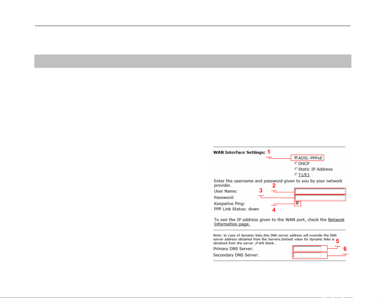
Configure WAN ADSL-PPPoE
ADSL-PPPoE (1)
Select to display these options. When selected the
WAN Ethernet port will perform a PPP negotiation to
obtain and IP address, this IP will be assigned to the
ppp0 interface viewable in the “Network Information
page” a link to this page is provided. The default
gateway and DNS servers are also sent to the system
in the DHCP reply.
User Name (2)
Enter user name your ISP has assigned to your DSL
account.
Password (3)
Enter password for your user name your ISP has
assigned to your DSL account
11
Page 12
VBP Series Configuration Guide
Keepalive Ping (4)
Selected by default to send an LCP-echo request, this is called a link control protocol “ping” not to be confused with ICMP
based ping. The PPP LCP “ping” interval is every 60 seconds; if 3 request are not responded to (180 seconds) the system
will re-establish the PPP connection. When this happens you may receive a different IP address. For this reason it is
recommended to setup a “Dynamic DNS” account, this allows remote locations to enter a DNS name to dial your location.
(see the Dynamic DNS page under “System”) see RFC 1661 for PPP related information.
Primary DNS Server (5)
Entering static DNS information for a dynamic WAN type will override what is received during PPP negotiation
Secondary DNS Server (6)
Entering static DNS information for a dynamic WAN type will override what is received during PPP negotiation
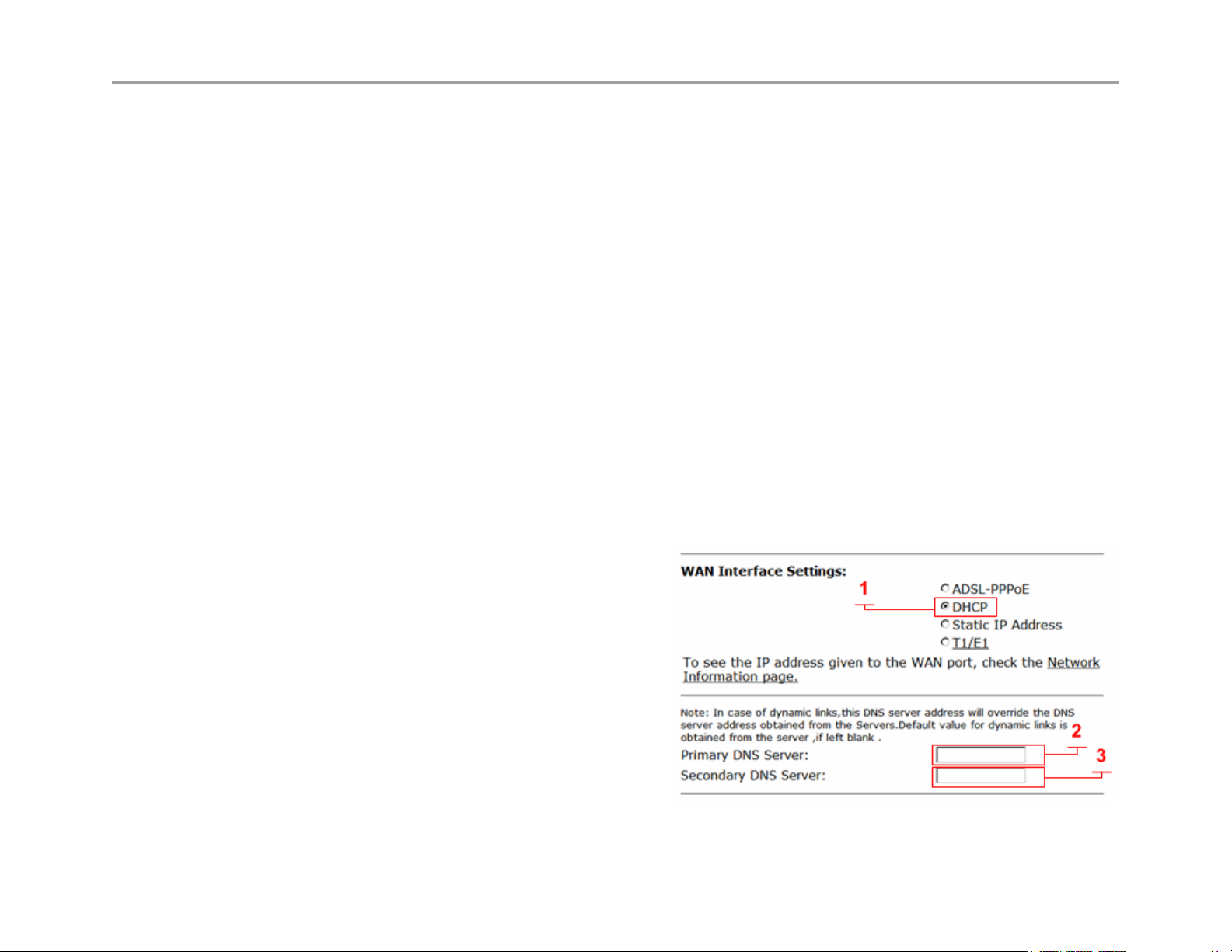
Configure WAN DHCP
DHCP (1)
Select to choose this option. When selected the WAN Ethernet port will perform a DHCP negotiation to obtain and IP
address, this IP will be assigned to the eth1 interface viewable in the “Network Information page” a link to this page is
provided. The default gateway and DNS servers are also sent to the system in the DHCP reply.
Primary DNS Server (2)
Entering static DNS information for a dynamic WAN type will override what is received during DHCP negotiation
Secondary DNS Server (3)
Entering static DNS information for a dynamic WAN
type will override what is received during DHCP
negotiation
12
Page 13
VBP Series Configuration Guide
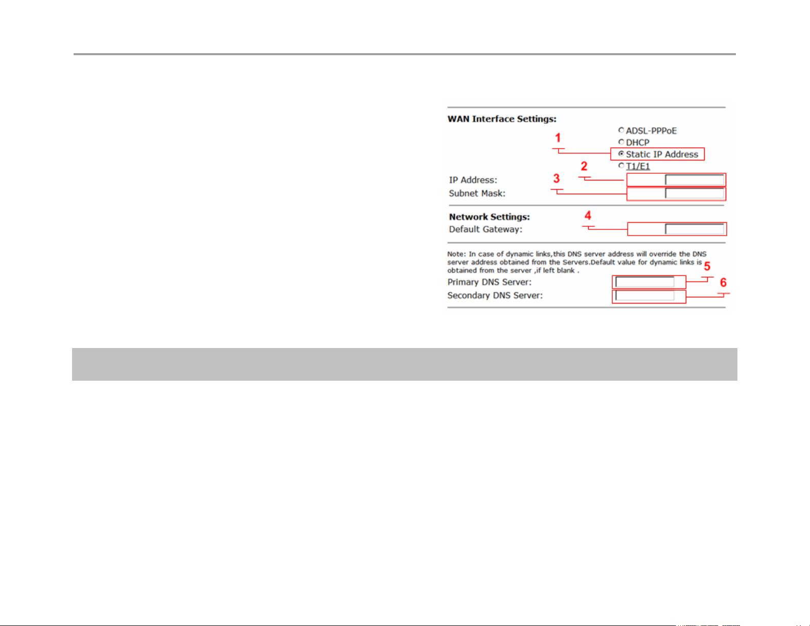
Configure WAN Static IP Address
Static IP Address (1)
Select to display these options
IP Address (2)
Enter IPv4 IP address
Subnet Mask (3)
Enter subnet mask as appropriate, default gateway
must be in this subnet
Default Gateway (4)
Enter IP address of the upstream (WAN) router
Primary DNS Server (5)
Enter primary DNS server IP
Secondary DNS Server (6)
Enter Secondary DNS server IP
Note: The VBP WAN interface must be assigned a publicly routable IP address. Assigning a RFC1918
address to the WAN interface is not supported
13
Page 14
VBP Series Configuration Guide
Configuring VBP-ST Network Settings
Configure Subscriber and Provider settings
1. Choose Network from the Configuration Menu.
2. Configure all parameters indicated, double check that you have the correct IP’s for the interfaces as defined
3. Click Submit.
A message indicates that service will be temporarily interrupted.
4. Click OK to confirm.
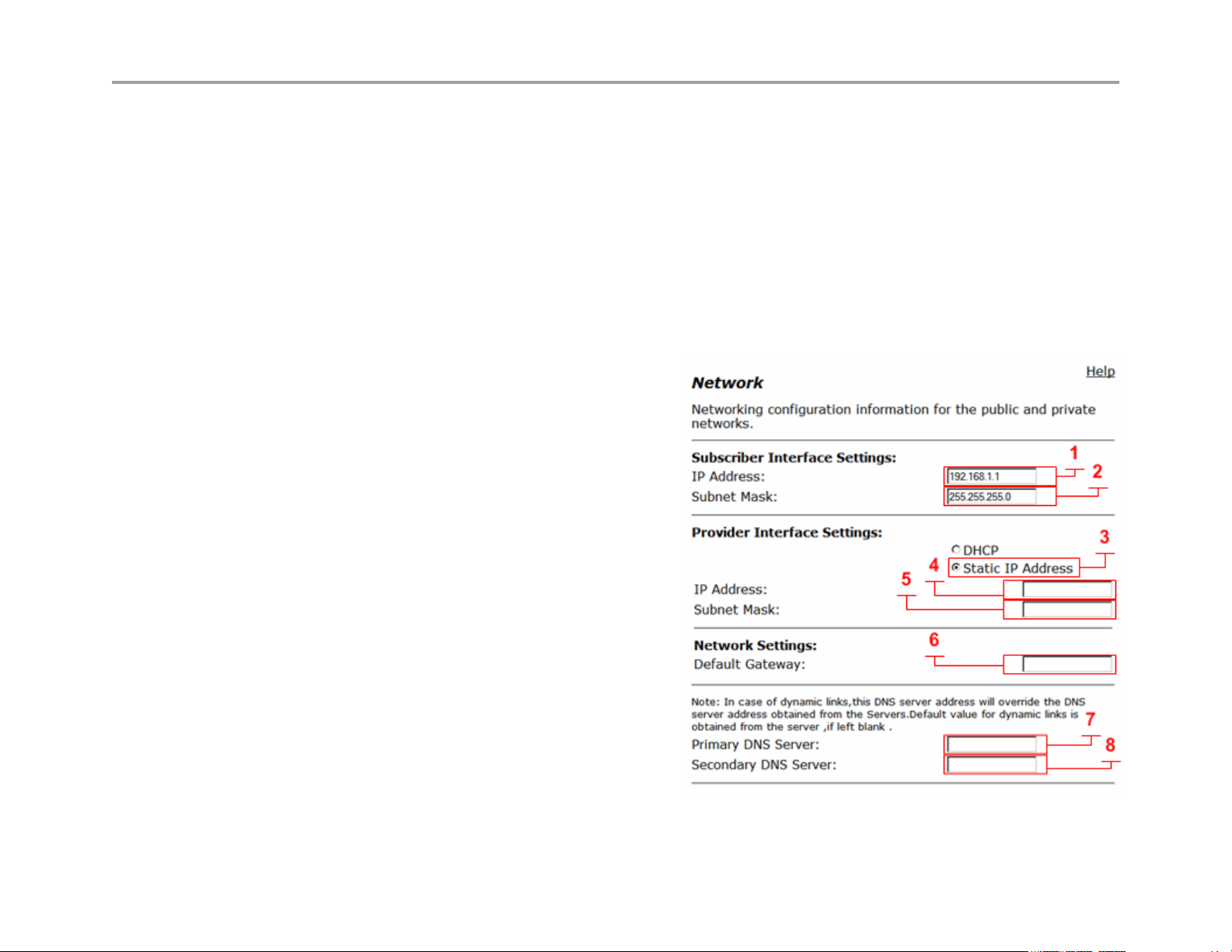
Subscriber Interface Settings
IP Address (1)
Enter the IPv4 IP address, while this interface is call “Subscriber”
its commonly placed on the Internet or WAN side of the network.
The default IP address is 192.168.1.1 while this IP is associated
to the LAN, it is used by default on the Subscriber interface. The
reason for this is for configuring the system for the first time for
documentation procedures of attaching your PC to “port 1” to
reach 192.168.1.1, when you reconfigure the Public IP on the
Subscriber interface, and the firewall is enabled, you will place
this interface on the public network
Subnet Mask (2)
Enter subnet mask as appropriate, default gateway must be in
this subnet
Default Gateway (6)
Enter IP address of the upstream (WAN) router
Primary DNS Server (7)
Enter primary DNS server IP
Secondary DNS Server (8)
Enter Secondary DNS server IP
14
Page 15

VBP Series Configuration Guide
Provider Interface Settings
Static IP Address (3)
Select to display these options, while DHCP is an option on
the Provider interface, it is not commonly used due to the
nature of H.323, and the dependencies that other H.323
network equipment have on the Provider or LAN network.
There are typically multiple devices that require entering this
IP statically as part of installing and configuring these other
H.323 devices, e.g. gatekeeper, MCU, other routers that
provide route entries to the VBP-ST. It is highly recommended
that you do not use DHCP on the Provider interface.
IP Address (4)
Enter IPv4 IP address, while this interface is called “Provider”
In most deployments this interface will be placed in the private
or LAN side of the network
Subnet Mask (5)
Enter subnet mask as appropriate, when creating “Route”
entries the gateways for the route entry must be within this
subnet.
15
Page 16

VBP Series Configuration Guide
Configuring LAN Settings
This section describes how to set up LAN parameters with and without VLANs. The VLAN configuration feature allows you to connect the
appliance to an Ethernet switch that has been configured to use VLANs. VBP-S and ST platforms do not support VLAN’s
Note: The VBP appliance is shipped with LAN IP address 192.168.1.1 and subnet mask 255.255.255.0
Configure LAN network settings without VLANs
1. Choose Network from the Configuration Menu.
2. The LAN Interface Settings area of the Network page shows the LAN IP address (192.168.1.1) and subnet mask (255.255.255.0).
3. Clear the Enable VLANs checkbox.
4. Click Submit.
A message indicates that service will be interrupted while the new interface is added.
5. Click OK to confirm.
Configure LAN network settings with VLANs
1. Choose Network from the Configuration Menu.
2. Select Enable VLANs.
3. Click Submit.
A message indicates that service will be interrupted while the new interface is added.
4. Click OK to confirm.
5. Click VLAN Settings to open the VLAN page.
6. Configure settings as appropriate for your VBP model.
Configuring VLANs
The VBP series appliance supports tagged and untagged VLANs. As specified in the IEEE 802.1q standard, tagged VLANs incorporate the VLAN
ID and priority in the packet header. Untagged VLAN packets do not include the VLAN ID or priority.
Most VBP series appliances (200EW, 4300T, 4350, 4350EW and the 5300/6400 series) provide support for multiple tagged VLANs. The 5300-E
and 6400-E series each support a single untagged VLAN; while the 200EW, 4300T, 4350, 4350EW support up to four untagged VLANs. VBP-S
and ST platforms do not support VLAN’s
All VBP-E series appliances support up to 16 VLANS.
16
Page 17

VBP Series Configuration Guide
Set up VLANs on the 4350
1. Choose System > VLAN Configuration from the Configuration Menu.
2. Choose 802.1 or 802.1q from the LAN Port Membership pull-down list. Click Modify. If 802.1 is selected, radio buttons are presented to
permit selection of a single VLAN. If 802.1q is selected, checkboxes are presented to permit selection of multiple tagged VLANs.
3. To add and configure a new VLAN, enter the new VLAN ID, IP address, and network mask. Click Add. A new VLAN entry is added to the
VLAN configuration. The mode of the physical port determines the rules for VLAN assignment:
a. 802.1 mode: Assign the port to a single VLAN.
b. 802.1q mode: Assign the port to multiple VLANs
4. Repeat steps 3 for each VLAN you wish to create.
Set up VLANs on the 5300-E and 6400-E series
1. Choose System > VLAN Configuration.
2. The screen displays the IP address and subnet mask of the default untagged VLAN. The LAN Ethernet port on the 5300 and 6400 can
have both a single untagged and multiple tagged VLANs. Each new VLAN that you add will be tagged only, the untagged VLAN is
represented as “eth0”, if changes to this VLAN are necessary go to the “Network” page and modify the “LAN Interface Settings”.
3. To add a tagged VLAN, enter the VLAN ID, IP address, and network mask, and click Submit.
A message indicates that service will be interrupted while the new interface is added.
4. Click OK to confirm.
5. Repeat steps 3 for each VLAN you want to create.
Delete a VLAN
1. Choose System > VLAN Configuration from the Configuration Menu.
2. Click the “trash can” icon to the right of the VLAN entry. It is not necessary to click Submit after deleting a VLAN.
Configuring Ethernet Interface Link Settings
You can modify the Ethernet interface link settings for the appliance, since “Auto-negotiate” interoperability can be problematic for real time
protocols, it is recommended to statically configure both VBP Ethernet ports and the switch ports the VBP’s interfaces are connected to.
Depending on the WAN link it may be necessary to adjust the WAN MTU size, this issue is typically seen on connections under T1 rates or, DSL
links and that depends on the DSL devices ability to set the MTU or MSS size.
17
Page 18

VBP Series Configuration Guide
Note: Take care when adjusting the Ethernet link rate. The device may become unreachable if an incompatible rate is set.
1. Choose System > Set Link.
2. Select a rate for each Ethernet link, or choose Auto-negotiate.
3. Click Submit.
A message indicates that service will be interrupted while the new interface is added.
4. Click OK to confirm.
SNMP Overview
The VBP series appliance can be managed remotely by an SNMP network management system such as HP Openview. SNMPv1, v2, and v3 and
the following MIBS are supported:
MIB-II (RFC 1213)
IF-MIB (RFC 2863)
SNMP MIB-V2 (RFC 3418)
TCP-MIB (RFC 4022)
IP-MIB (RFC 2011)
UDP-MIB (RFC 4113)
SNMP-VIEW-BASED-ACM-MIB (RFC 3415)
SNMP-MPD-MIB (RFC 3412)
SNMP-USER-BASED-SM-MIB (RFC 3414)
SNMP-FRAMEWORK-MIB (RFC 3411)
All MIB variables are read only. The SNMP MIB-V2 variables sysContact, sysLocation and sysName can be set through the web GUI.
The web GUI supports the configuration of multiple SNMP v1 and SNMP v2 trap destinations. The traps are sent to each of the configured
destination using the appropriate protocol version and community string. SNMPv3 supports only one trap destination.
The VBP series appliance sends the following traps:
coldStart
authenticationFailure
linkup
linkDown
18
Page 19
VBP Series Configuration Guide
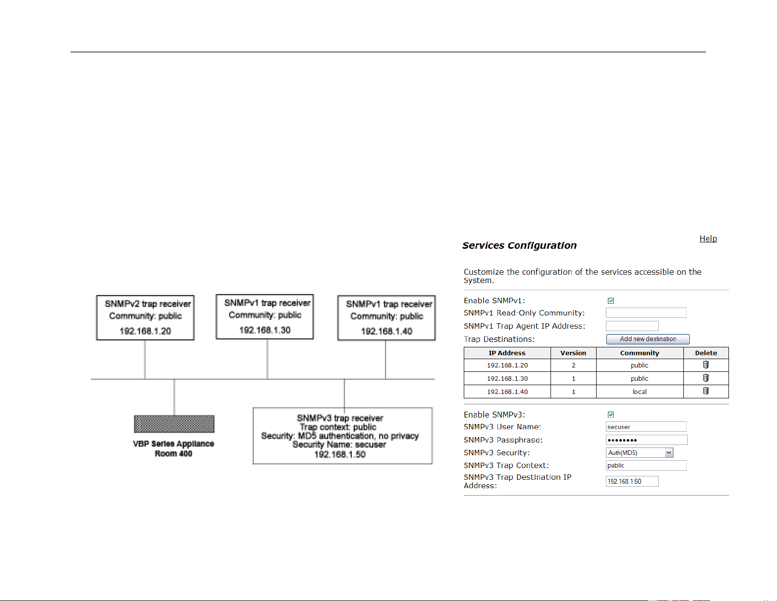
Configure SNMP
1. Choose System > Services Configuration.
2. To use SNMPv1 or SNMPv2, select the Enable SNMPv1 checkbox. By default, the agent-address field in SNMPv1 traps is set to the
address of the interface that is used to send the trap. You can assign a custom IP address by entering a value in the SNMPv1 Trap Agent
IP Address field.
3. To use SNMPv3, check the Enable SNMPv3 checkbox. Enter the user name, passphrase, security method, trap context, and destination
trap IP address. The following security methods are supported:
4. None: No authentication and no Privacy
5. Auth(MD5): Authentication using MD5
6. AuthPriv(MD5/DES): Authentication using MD5 and Privacy using DES protocol
7. Click Submit.
A message indicates that service will be temporarily interrupted.
8. Click OK to confirm.
The figure below displays the VBP configuration for the SNMP Network setup:
Figure 1. SNMP Configuration Example
19
Page 20

VBP Series Configuration Guide
Disable SNMP
1. Choose System > Services Configuration.
2. Clear the Enable SNMPv1 or Enable SNMPv3 checkbox.
A message indicates that service will be temporarily interrupted.
3. Click OK to confirm.
Delete an SNMP trap
1. Choose System > Services Configuration.
2. Click the “trash can” icon for the trap.
3. Click Delete.
Configuring DHCP Services
You can configure DHCP services with and without VLANs on all E series appliances. You can also relay DHCP requests to an external DHCP
server or use the DHCP server included in the VBP series appliance.
DHCP Relay
When you enable DHCP relay and point to a valid DHCP server, you determine that all DHCP requests will be forwarded to that server. Local
DHCP and DHCP Relay are mutually exclusive. That is, turning on DHCP Relay automatically turns off local DHCP, and turning on DHCP
automatically turns off DHCP Relay.
As you configure the functions featured on the page, review the following list:
Enable DHCP Relay
Select this checkbox to enable DHCP Relay.
DHCP Relay IP Address
Enter the IP address of the DHCP server where the system will forward traffic.
1. Choose DHCP Relay from the Configuration Menu.
2. Check Enable HDCP Relay
3. Enter the DHCP Relay IPv4 IP Address
4. Click Submit.
A message indicates that service will be temporarily interrupted.
5. Click OK to confirm.
20
Page 21
VBP Series Configuration Guide
DHCP Server
DHCP is a protocol that enables PCs and workstations to get temporary or
permanent IP addresses (out of a pool) from centrally administered servers.
All VBP E series appliances can act as a DHCP server, assigning IP
addresses to devices in the network. You can configure blocks of IP
addresses, default gateway, DNS servers, and other parameters that can
be served to requesting devices.
Table 1 lists the DHCP options supported by the systems DHCP Server.
DHCP on your system does not have to be enabled if a DHCP server exists
elsewhere in your company network. It can be disabled. When you have
enabled the DHCP server, you can turn it on or off using the Enable DHCP
Server box without having to change other settings.
The DHCP IP Address Ranges table shows the dynamic addresses to use
for the LAN devices. Enter individual DHCP IP addresses or a range.
Assign static IP addresses for any common-access devices, such as
printers or fax machines.
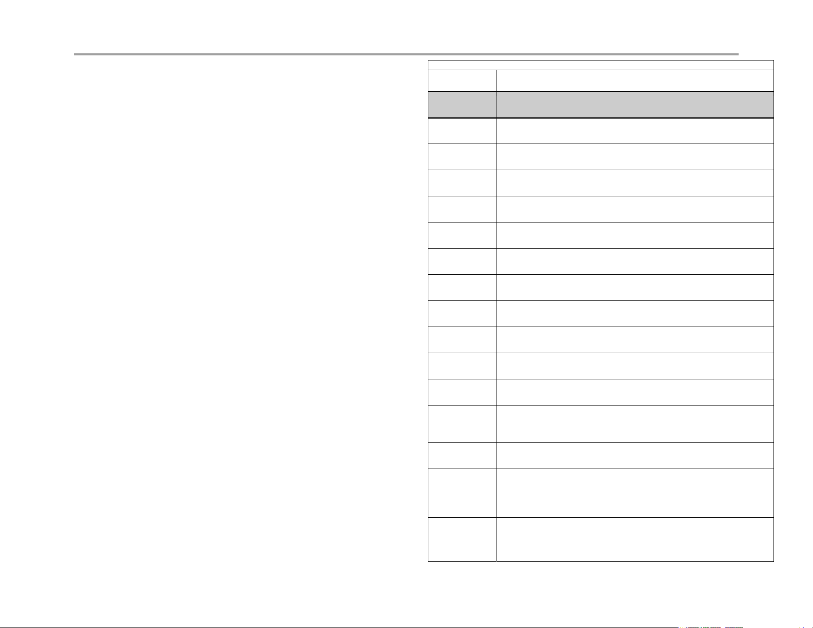
Table 1 DHCP Server Options
Option Description
1 Subnet Mask - LAN Netmask of the VBP Network page
2 Time Offset
3 Router - LAN IP of the VBP Network page
6 DNS Server - DNS IP, Network page
42 NTP Servers
51 IP address lease time - Lease duration in seconds, DHCP page
53 DHCP Message Type - Set by DHCP server
54 Server Identifier - LAN IP of the VBP
66 FTP Server name
67 Boot file name
129 Call Server IP Address - VLAN ID Discovery
150 Phone Image TFTP Server IP - LAN IP of the VBP, Network
Page
151 MGCP Control Server IP - LAN IP of the VBP, Network Page
159 Allows the user to enter a text string in the form of a FQDN. It can
be used to point phones to the domain name of a TFTP server
using HTTP.
160 Allows the user to enter a text string in the form of a FQDN. It can
be used to point phones to the domain name of a TFTP server
using HTTPS.
21
Page 22
VBP Series Configuration Guide
Configuring DHCP Server
Configuring DHCP Server on the VBP appliance includes enabling the server and configuring the DHCP IP Address range to be used by LAN
devices. Use the following procedure to configure DHCP.
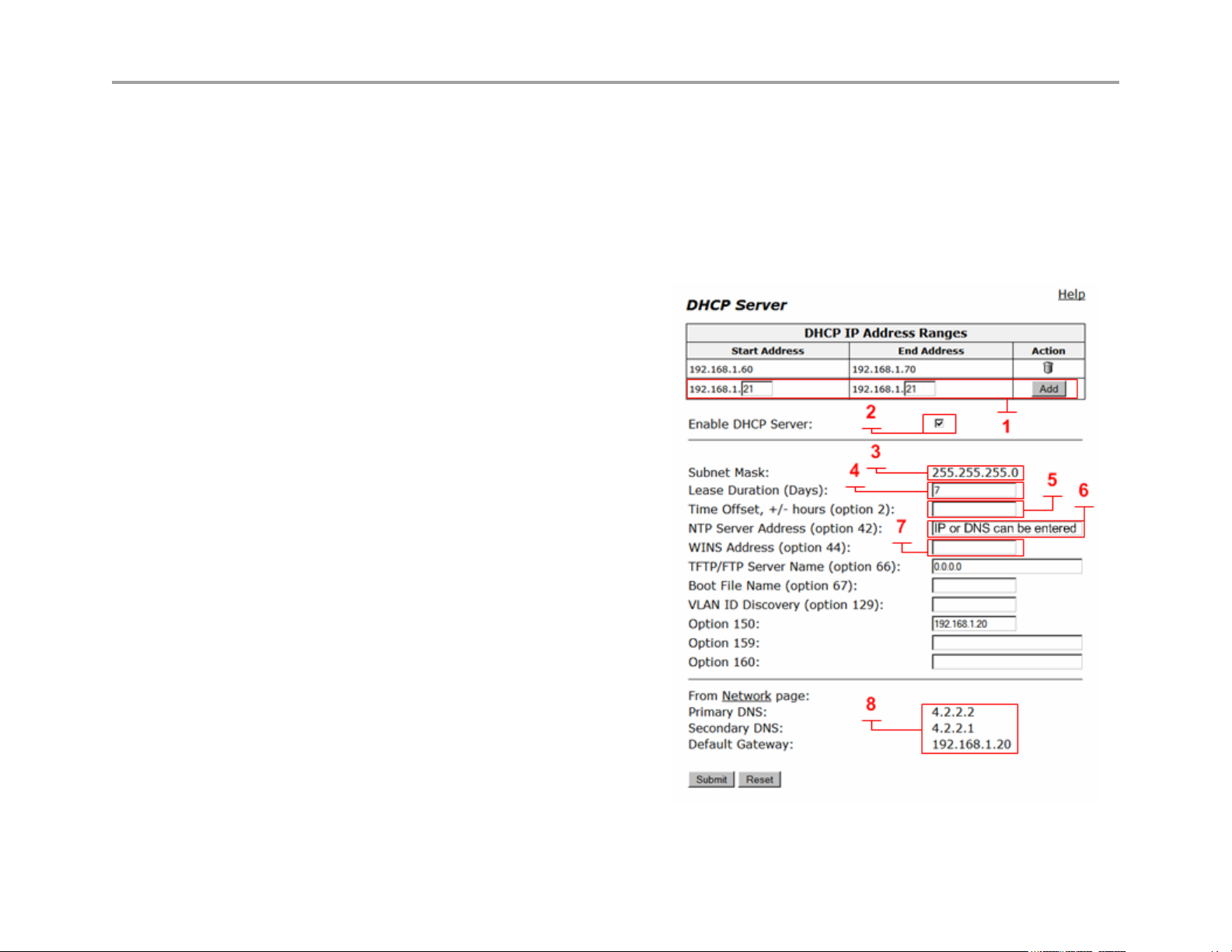
Configure DHCP
Choose DHCP Server to open the DHCP Server page.
As you configure the functions featured on the page, review the following list:
DHCP IP Address Ranges Table (1)
Shows the dynamic addresses to use for the LAN devices.
Enter individual DHCP IP addresses or a range. To configure
an address range, select the appropriate values and click Add.
To delete an address, Click the trash can icon. When adding a
new range you must click submit to apply the new range to the
DHCP server.
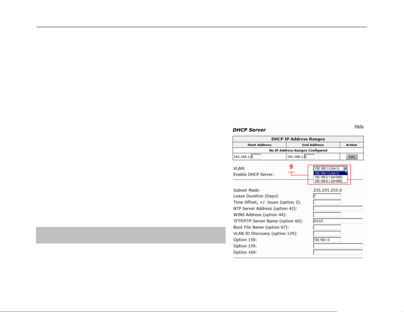
VLAN (9) see next page for reference
Select the VLAN served by the DHCP server.
Enable DHCP Server (2)
Select this checkbox to enable the DHCP server.
Subnet Mask (3)
Subnet Mask address for the DHCP pool. This mask is
configured from the LAN subnet mask in the Network page
Lease Duration (Days) (4)
Enter the number of days you want to lease the DHCP service.
This is the amount of time a DHCP service will remain
connected without lapse. The value can be 1 day minimum
and 30 days maximum. Note: when the DHCP lease has
expired and the client requests a new IP, it is common for the
system to assign the same IP to that system MAC address, if 2
clients make a DHCP request at the same time the lease
expires, it is “possible” the system will not assign the same IP.
Time Offset, +/- hours (option 2) (5) (optional)
Set the time offset in hours from UTC (Universal time Code) for your local location.
22
Page 23
VBP Series Configuration Guide
NTP Server Address (option 42) (6) (optional)
Set the Network Time Protocol (NTP) address that is served out by DHCP. This field can have a IP address or DNS name of a
valid NTP server. Note: if a DNS name is entered in this field the system will perform a DNS A record lookup and use the IP
address returned from this lookup to respond to the DNS request from the client as option 42, if the systems DNS server’s
configured on the Network page are unresponsive, the DHCP response will be delayed.
WINS Address (option 44) (7) (optional)
Enter the IPv4 IP address of your WINS server. The Windows Internal Naming Service (WINS) is a service that keeps a database
of computer name-to-IP address mappings so that computer names used in Windows environments can be mapped to IP
addresses.
TFTP/FTP Server Name (option 66) (optional)
Set the TFTP/FTP server name that is served out by DHCP. By default, this option is the same as the TFTP server on the ALG
page.
VLAN ID Discovery (option 129) (optional)
Set the VLAN ID that devices will acquire after rebooting.
From the Network page (8)
This area is for information only, the DNS IP’s shown and the
Default Gateway shown will be sent to the client in the DHCP reply
Configuring DHCP With VLANs
This section describes using the DHCP Server capability on the VBP series
appliance with configured VLANs. The VBP series appliance supports a maximum
of 16 VLANs, all of which could be associated with the DHCP Server. The following
are default VLAN IDs used on the VBP appliance:
• VLAN ID 1 (formerly 2730)-- used for management interface (VBP
5300 and 6400 appliances only)
• VLAN ID 500 -- used for video
• VLAN ID 600 -- used for data
Note: To use DHCP with VLANs, the VLAN capability must
be enabled and VLANs configured.
Once VLAN capability is enabled and VLANs configured, use the following
procedure.
1. Select the VLAN to be used from the drop down list.
2. Check Enable DHCP Server.
3. Add DHCP IP Address Ranges (Scope). In the DHCP IP Address Range table input the starting and ending IP address, then click Add.
4. Click Submit, when adding an extra IP Address Range to this server you must click submit to apply the new range.
23
Page 24
VBP Series Configuration Guide
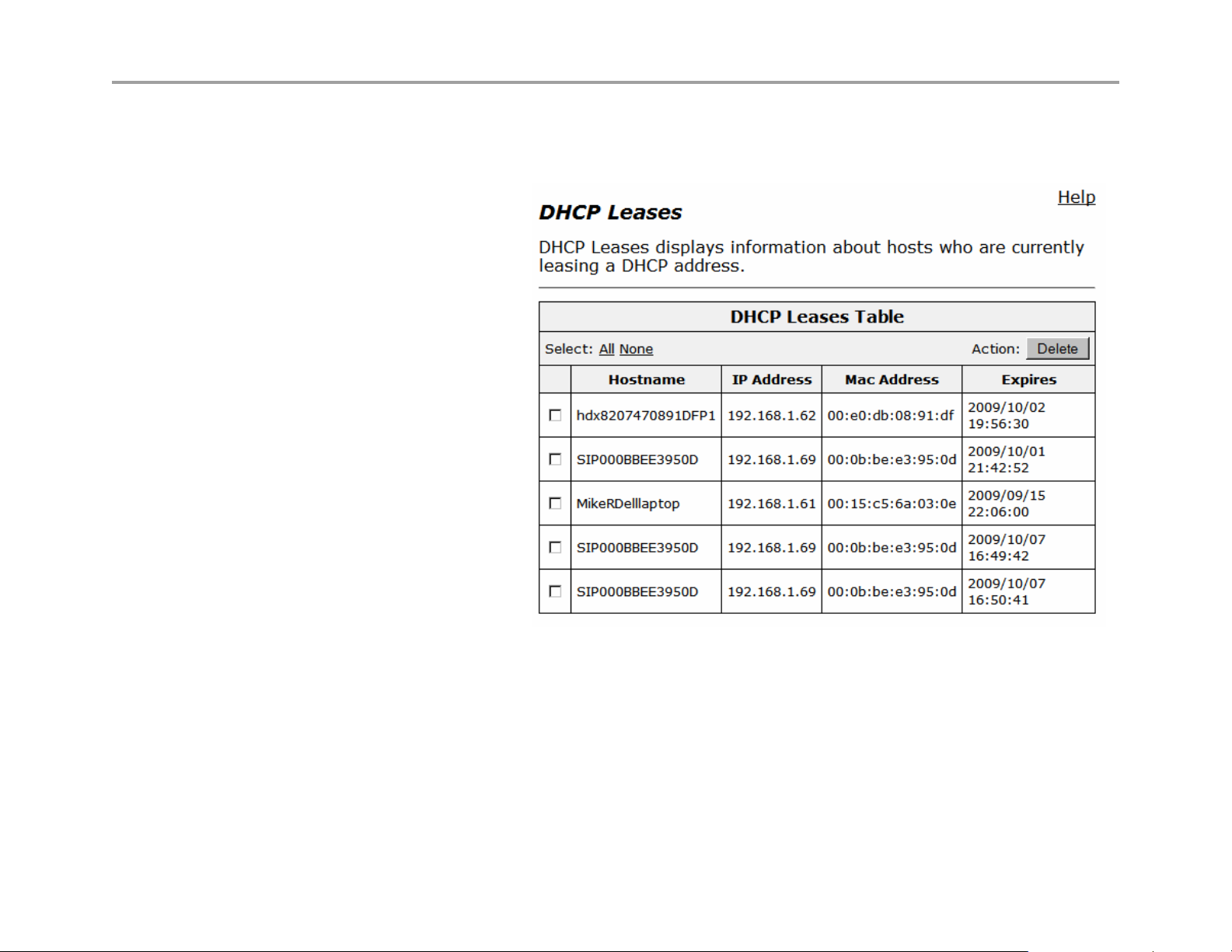
DHCP Leases
The DHCP Leases page displays view-only information about clients that are currently leasing a DHCP address.
View DHCP lease information
Choose DHCP Server > DHCP Leases.
Hostname
Name of the client that is currently using
this DHCP address.
IP Address
IP address of the client.
MAC Address
MAC address of the client.
Expires
Date and time that the DHCP address
expires.
Delete
Select the client you wish to delete and
click “Delete”
24
Page 25

VBP Series Configuration Guide
Configuring DNS for ANNEX O support
ANNEX O http://www.itu.int/rec/T-REC-H.323/en is a recommendation within the H.323 standard to define a means in which endpoints and border
elements standardize on a common dial plan. ANNEX O is also referenced as URI or URL dialing in the form of john.smith@example.com
user@host format.
The user portion of this format will be the H.323 endpoints E.164 and or H.323-ID. When the endpoint registers to the gatekeeper with these
aliases the endpoint can be called with either as the user portion. The host portion can be a legal numeric IP address or a fully qualified domain
name (FQDN) a company has registered, in this explanation we will reference example.com and discuss the DNS infrastructure and configurations
needed. Using a FQDN for H.323 services will require specific SRV and A records to be created on the DNS sever.
If you choose to standardize on ANNEX O as your dial plan DNS records will be to needed to simplify the method in which remote locations call
into your enterprise that could have a single VBP or multiple VBPs installed at the border. Outbound calls from the VBP to remote domains or
enterprises will depend on what the user dialed and how that location has deployed there H.323 solution and domain records.
Discussed in this section is a simplified explanation of DNS SRV records and how to configure them for your domain for incoming calls. When
users on the enterprise call outbound the VBP will perform SRV and A record queries as described for the H.323 endpoint as both use a similar
but different DNS application client to perform the request.
SRV records also provide a method to prioritize which VBP receives incoming calls, or with the SRV priority field set to an equal value a round
robin method could be supported to distribute the load throughout the enterprise. Using a round robin approach will depend on how the calling
H.323 DNS client supports the usage of the priority and weighting fields, some H.323 endpoints may not support this feature correctly.
You will need to configure the following on your DNS server
• SRV service records – Service records specify the A record or FQDN of the VBP
• A Records – Defines the IPv4 address of the VBP
SRV record format as defined by http://www.ietf.org/rfc/rfc2782.txt
locations to reach your enterprise. The method in which most inbound connections will be made will be using the _h323cs service lookup to
support an adhoc call using the john.smith@example.com
ANNEX O dial plan such as dialing the destination alias E.164 e.g. 8315551234 and require a _h323ls service type.
The proto field should be set to the service respectively e.g. _h323cs is TCP proto and _h323ls is UDP proto
_Service._Proto.Name TTL Class SRV Priority Weight Port Target
• Service: The symbolic name of the service e.g. _h323cs or _h323ls – this field is case sensitive
• Proto: The protocol type e.g. _tcp or _udp – this field is case sensitive
format. Some VBP deployments may require gatekeeper neighboring to support a non
Configuring your DNS settings are for services to your VBP for remote
or
25
Page 26

VBP Series Configuration Guide
• TTL: Standard DNS time to live field
• Class: Standard DNS class field (this is always IN)
• Priority: Refers to the priority of this target host, a lower value receives a higher priority
• Weight: The weight field specifies a relative weight for entries with the same priority
• Port: The port of this target host of this service
• Target: The domain name of the target host, there must be a A record as this name
A record format as defined by http://www.ietf.org/rfc/rfc1034.txt
Configuring your DNS server A record type allows you to map a name to a IPv4
address. Each VBP installed on the network will have a unique IPv4 WAN address assigned and the same applies for the DNS A record name
configured. Example;
Name Type Data
vbp1.example.com IN A 12.48.270.1
vbp2.example.com IN A 12.48.280.1
DNS servers can be different in configuring the SRV or A record parameters, please consult with your IT staff or DNS provider in configuring the
records required for your specific VBP deployment. In the diagram below the enterprise VBP deployment has installed 2 VBP systems in different
locations on the WAN network, the reasons for this could be for network redundancy or to distribute the incoming calls between the 2 VBP’s. For
the example DNS records we will assume a redundant VBP model is desired.
Create DNS A records for both VBP’s on your DNS server as shown above, then create the SRV records to related the A records. Example;
Name Type Data TTL
_h323cs._tcp.example.com IN SRV 0 50 1720 vbp1.example.com 1 day
_h323cs._tcp.example.com IN SRV 1 50 1720 vbp2.example.com 1 day
You will need to configure SRV and A record entries for all the VBP’s installed on the network as they relate to the _h323cs service for
example.com.
In the above SRV example vbp1.example.com is set for a priority of 0, weight 50, port 1720 (default for call setup) and vbp2 is set for priority 1,
weight 50, port 1720. The calling endpoint would send the call SETUP to vbp1 unless vbp1 has become unresponsive to the request, when the
call to vbp1 times out, the calling endpoint will use the next lower priority to forward the call to, in this example the call will go to vbp2.
The calling endpoint will query the DNS server for an SRV record first, if there is no such record found the H.323 endpoint will perform an A record
query, if there is no such record found the H.323 endpoint will fail the call and the user will need to dial the destination by the IPv4 address.
An important item to note is, example.com is the destination domain, this domain will usually have different services configured, HTTP, Email etc.
Web browsers and email clients will query the DNS server for their service type, H.323 endpoints and border elements are another configured
service type to the domain.
26
Page 27
VBP Series Configuration Guide
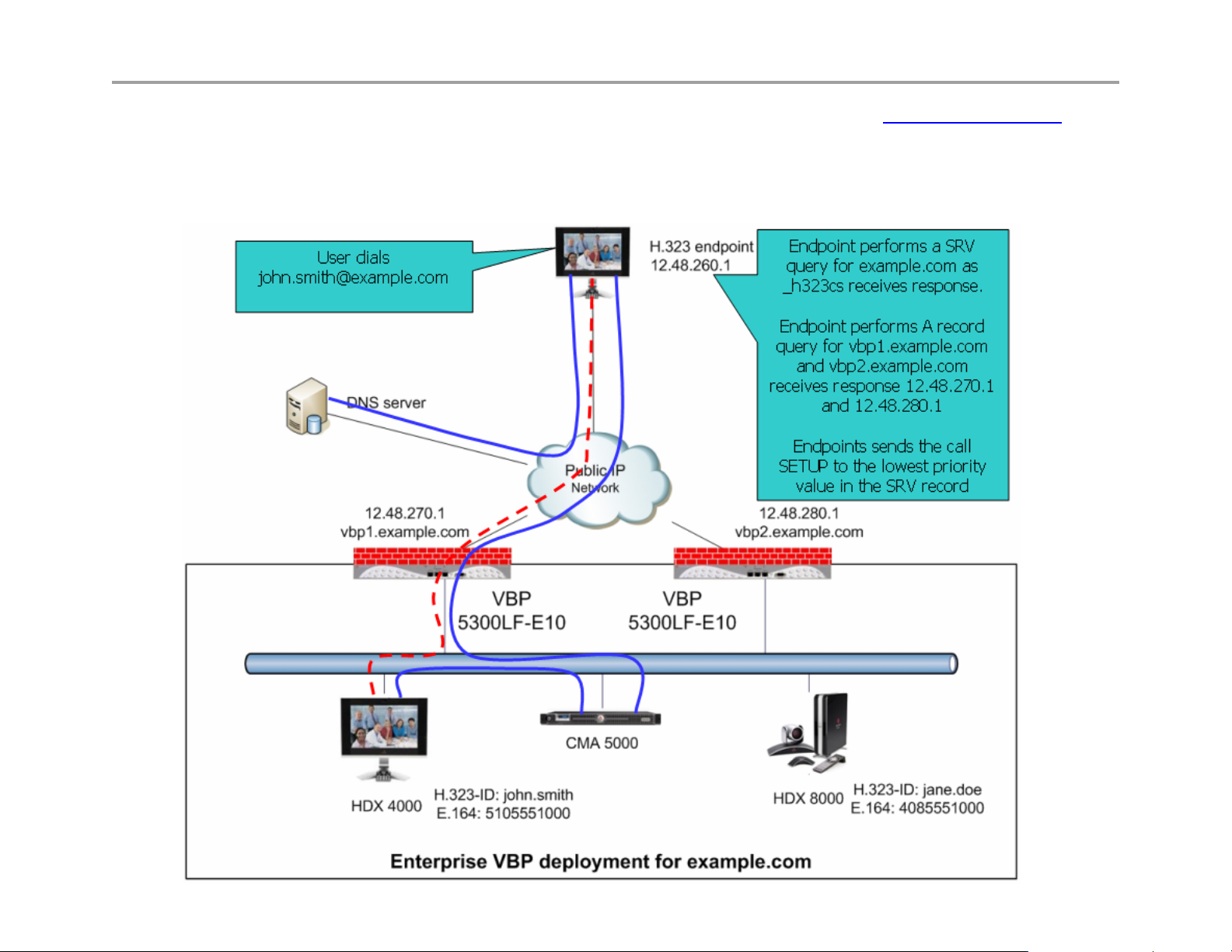
Using the SRV and A record examples above the below diagram shows an example of a H.323 endpoint dialing john.smith@example.com the
H.323 endpoint will perform a SRV query on example.com to the DNS server address configured in the endpoints network parameters. The DNS
server will reply back with a DNS SRV query response with vbp1.example.com and vbp2.example.com. The endpoint will now perform a DNS A
record query for vbp1.example.com and vbp2.example.com. The DNS server will reply back with a DNS A record response with 12.48.270.1 and
12.48.280.1. The endpoint will now send a call SETUP to 12.48.270.1 with a destination alias of john.smith. If 12.48.270.1 is unavailable, the
endpoint will timeout the session and create a new call SETUP to 12.48.280.1
27
Page 28

VBP Series Configuration Guide
Diagnose your DNS settings
Adding or changing DNS records can take 24 hours to propagate out internet based DNS servers, if there are users that cannot reach your VBP it
may simply be the DNS server they are using have not been updated yet.
You can perform a simple request from your computer by opening a command prompt and typing
nslookup -q=srv _h323cs._tcp.example.com
C:\Documents and Settings\Jane Smith>nslookup -q=srv _h323cs._tcp.example.com
Server: vnsc-bak.sys.gtei.net
Address: 4.2.2.2
Non-authoritative answer:
_h323cs._tcp.example.com SRV service location:
priority = 1
weight = 50
port = 1720
svr hostname = vbp2.example.com
_h323cs._tcp.example.com SRV service location:
priority = 0
weight = 50
port = 1720
svr hostname = vbp1.example.com
Now perform a ping to the hostname for both entries
C:\Documents and Settings\Jane Smith>ping vbp1.example.com
Pinging vbp1.example.com [12.48.270.1] with 32 bytes of data:
Reply from 12.48.270.1: bytes=32 time=94ms TTL=49
Reply from 12.48.270.1: bytes=32 time=95ms TTL=49
Reply from 12.48.270.1: bytes=32 time=93ms TTL=49
Reply from 12.48.270.1: bytes=32 time=107ms TTL=49
Ping statistics for 12.48.270.1:
Packets: Sent = 4, Received = 4, Lost = 0 (0% loss),
Approximate round trip times in milli-seconds:
Minimum = 93ms, Maximum = 107ms, Average = 97ms
28
Page 29

VBP Series Configuration Guide
Firewall rules for securing the network
VBP Firewall Basics
The VBP system deploys a Linux iptables firewall, and as a converged system, this firewall is controlled by internal applications dynamically. The
H.323 ALG application uses iptables dynamically; as H.323 calls are being proxied and modified at Layer 5, the firewall ports for TCP H.245
messages are dynamically opened. This H.245 TCP connection is used by the endpoints to send media related parameters, what codecs can be
used for audio and video, how many channels will be used, what ports both endpoints intend to send/receive RTP on, etc. During this negotiation
the VBP NAT/PAT’s this information as messages pass through the system, since the VBP provides the NAT (network address translation) PAT
(port address translation) function, the VBP will know what UDP ports and IP’s to allow to incoming connections.
This process happens dynamically, there is nothing to configure on the Firewall page to setup the system. The below methods are mainly for call
control, as soon as the call control is allowed the system will allow the RTP media ports dynamically. TCP Port 1720 is used by H.323 devices as
the call control port and more important is the presence of the TCP port 1720 connection; if this connection is closed by any device in the path, the
endpoints will disconnect the session and the VBP will shut down access to the UDP media ports dynamically. During normal call control when a
user hangs up the system, there are normal disconnect messages that happen at Layer 5 when a system wishes to disconnect, the end result
after these Layer 5 messages have terminated normally is both endpoints will close the TCP port 1720 connection causing all devices between the
endpoints to remove their NAT/PAT contracts.
29
Page 30
VBP Series Configuration Guide
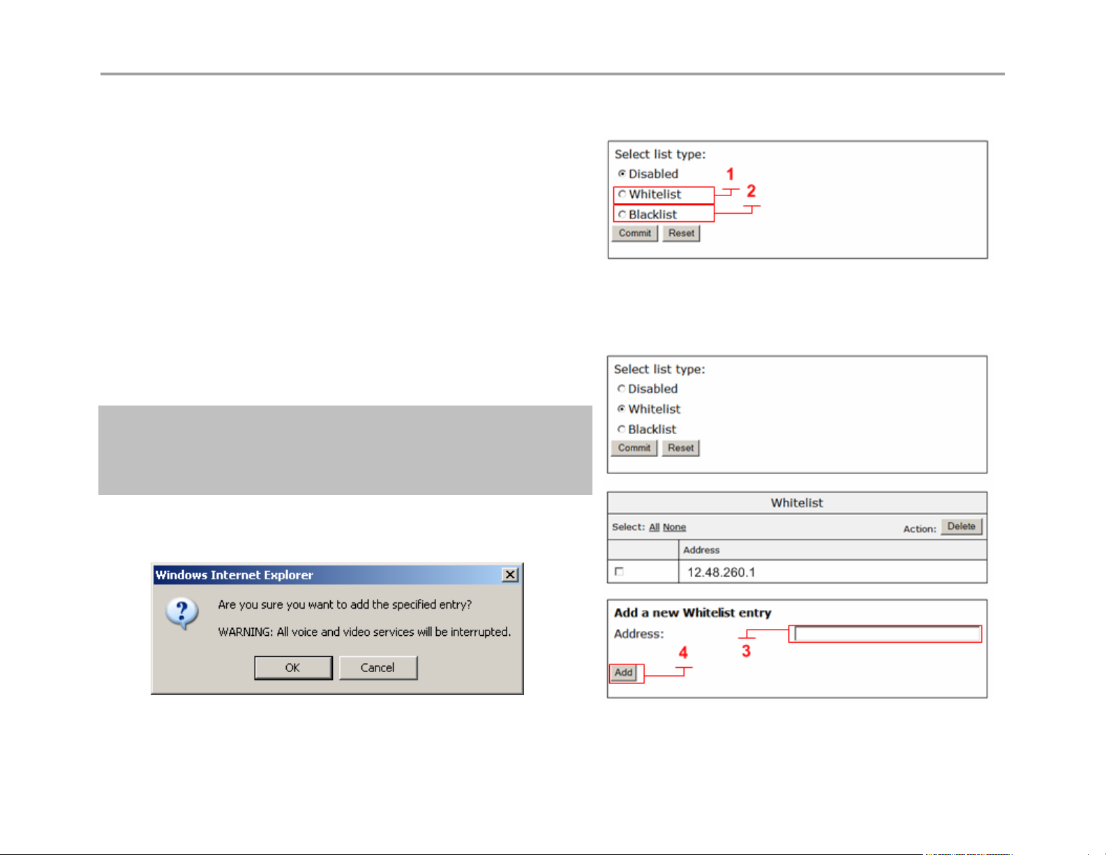
Configure the VBP-E Whitelist/Blacklist
1. Select - > VoIP ALG
2. Select - > H.323
3. Select - > Whitelist/Blacklist
4. Click Whitelist (1) to deny all H.323 incoming calls by default and
accept the listed addresses.
5. Click Blacklist (2) to accept all H.323 incoming calls by default and
deny the listed addresses.
6. Select Commit
When the system comes back up you will now have the ability to add IPv4 addresses.
7. Enter the IPv4 Address (3) and click Add (4)
8. The system will warn you this action will cause active calls to be
interrupted.
Note: This feature is designed to allow or deny TCP port
1720 on the WAN or Subscriber interface. This feature is
not designed to block outbound access from the LAN or
Provider interface.
30
Page 31

VBP Series Configuration Guide
VBP-E or VBP-S and ST blocking management ports
It may be necessary to block un-encrypted methods of managing the VBP for security reasons. By default the VBP-E system accepts
management port connections on the LAN interface.
VBP-E management ports
• Port 80 – HTTP
• Port 443 – HTTPS
• Port 22 – SSH
• Port 23 – Telnet
• Port 161 – SNMP
You can define rules to block LAN side access to these ports.
CAUTION: If you plan to manage the system with HTTPS, you must configure a certificate in the
“HTTPS Certificate” page before the system will accept HTTPS requests. You should test an HTTPS
connection to the system before you enter the rule that will DROP port 80 HTTP requests.
To block HTTP
iptables -I INPUT -i eth0+ -p tcp --dport 80 -j DROP
To block Telnet
iptables -I INPUT -i eth0+ -p tcp --dport 23 -j DROP
To block SNMP
iptables -I INPUT -i eth0+ -p tcp --dport 161 -j DROP
Most security teams will allow HTTPS and SSH as both protocols are SSL encoded
31
Page 32

VBP Series Configuration Guide
By default the system allows ICMP ping to the WAN/LAN interfaces
To block ICMP on the LAN interface
iptables -I INPUT 1 -i eth0+ -p icmp -j DROP
To block ICMP on the WAN interface
iptables -I INPUT 1 -i eth1+ -p icmp -j DROP
To block ICMP on both interfaces
iptables -I INPUT 1 -p icmp -j DROP
Trusted Management Addresses
Trusted Management Addresses are configured to control access to management functions on a VBP-E to a given IP address or subnet. Enter the
appropriate information in Trusted Management Addresses. The logic for Trusted Management Addresses is easy to follow: By entering one or
more IP addresses or subnets into this field, the VBP-E Series will create ACCEPT rules for the Management protocol defined in the Basic WAN
Firewall Settings area (HTTP/HTTPS/Telnet/etc.) for the IP addresses entered, and drop rules for all other IP addresses.
1. Decide which IP/subnets will be allowed access
2. Decide which management type will be allowed
3. Select the Management type in Basic Firewall
Settings area
4. Enter the relevant IP address information in
Trusted Management Addresses section
5. Click - >Submit
32
Page 33

VBP Series Configuration Guide
VBP-S or ST management ports
• Port 80 – HTTP
• Port 443 – HTTPS
• Port 22 – SSH
• Port 23 – Telnet
• Port 161 – SNMP
VBP-S or ST systems have a different firewall concept, the VBP-S or ST is traditionally placed on the Enterprise security boundary. The VBP-S or
ST could be placed in a Service Provider model which would have public IP’s on both interfaces, this is the reason the system uses the term
Provider/Subscriber instead of WAN/LAN. With this in mind, unlike the Firewall page in the VBP-E, which only blocks management port access
from the WAN side, the VBP-S or ST applies the allow/deny rules by checking or un-checking the desired management access to both
Provider/Subscriber interfaces. By un-checking HTTP access, the system will create rules to block port 80 request on both interfaces.
The below rules are provided for both interfaces, as you may want to allow HTTP on the Provider side and block HTTP on the Subscriber side, in
this case you will have HTTP checked on the Firewall page and then insert the rule to block port 80 HTTP on the Subscriber interface.
CAUTION: If you plan to manage the system with HTTPS, you must configure a certificate in the
“HTTPS Certificate” page before the system will accept HTTPS requests. If you are enabling the Access
Proxy, you will need to re-map HTTPS to an alternate ports, Access Proxy requires the use of port 443
To block HTTP on the Subscriber Interface
iptables -I INPUT -i eth0+ -p tcp --dport 80 -j DROP
To block Telnet on the Subscriber Interface
iptables -I INPUT -i eth0+ -p tcp --dport 23 -j DROP
To block SNMP on the Subscriber Interface
iptables -I INPUT -i eth0+ -p tcp --dport 161 -j DROP
33
Page 34

VBP Series Configuration Guide
To block HTTP on the Provider Interface
iptables -I INPUT -i eth1+ -p tcp --dport 80 -j DROP
To block Telnet on the Provider Interface
iptables -I INPUT -i eth0+ -p tcp --dport 23 -j DROP
To block SNMP on the Provider Interface
iptables -I INPUT -i eth0+ -p tcp --dport 161 -j DROP
Most security teams will allow HTTPS and SSH as both protocols are SSL encoded
By default the system allows ICMP ping to the WAN/LAN interfaces
To block ICMP on the Subscriber interface
iptables -I INPUT 1 -i eth0+ -p icmp -j DROP
To block ICMP on the Provider interface
iptables -I INPUT 1 -i eth1+ -p icmp -j DROP
To block ICMP on both interfaces
iptables -I INPUT 1 -p icmp -j DROP
34
Page 35

VBP Series Configuration Guide
CERT Advisory CA-2004-01
When performing a security scan of the VBP system, the scan results may indicate a vulnerability for this CERT advisory. Most port scanning
application detect the presence of the well known H.323 ports, UDP 1719 and TCP 1720 and flag this as a concern to be addressed. Below are
the details of the CERT advisory and the version of the H.323 stack the VBP uses.
The VBP uses a Linux kernel “Linux 2.4.24-uc0”
The following link provides the concerns for the CERT advisory CA-2004-01
http://www.cert.org/advisories/CA-2004-01.html
At the following link, you will see:
http://www.voxgratia.org/docs/faq.html#1_10
“The NISSC
protocol. This announcement was also released by CERT
All releases of PWLib after v1.6.0 contain fixes for the vulnerabilities demonstrated by the NISCC test suite. This includes the
Janus and Pandora baseline releases and all subsequent stable and development code releases.”
In the release notes for version 5.1.0 you will find the following statement
“Updated the H.323 stack to the Pandora release (version numbers:
pwlib 1.7.5, openh323 1.14.4). This version of the stack has numerous
fixes, most importantly the security issues discovered in the ASN.1
encoder/decoder have been fixed.”
The key to these statements is “All releases of PWLib after v1.6.0 contain the fixes” for this advisory the current Polycom version is
“Pandora release (version numbers: pwlib 1.7.5, openh323 1.14.4”
The above concerns were addressed in VBP version 5.1.0
The current firmware version of VBP is 9.1.5.1
announced on 13 January 2004 that they had discovered vulnerabilities in several implementations of the H.323
as Advisory CA-2004-01.
35
Page 36

VBP Series Configuration Guide
Implementing Polycom VBP with a Third-Party
Firewall
This section describes an issue that exists when certain application protocols such as H.323 are used when communicating across a NAT, or
third-party firewall. It is common for third-party firewalls to cause issues with advanced H.323 features such as AES-encrypted calls,
People+Content or H.239 dual-stream calls, and routed-mode gatekeeper services. This section describes the issues and how you can implement
VBP so that H.323 communications take place successfully.
Describing the Issue Between H.323 Communications and NAT
H.323 endpoints exchange data during call setup to determine how and where they will communicate. These messages are transmitted as
segments in TCP sessions for Call Setup (for H.225 messages) and Call Control (for H.245 messages). The packets contain the IP address and
port number of the given endpoint. This ensures, for example, that each endpoint knows the unique Layer 3 address to send media to, and the
port number the endpoint is requesting the far site to use. For example, for an H.245 Open Logical Channel (OLC) message, the receiving
endpoint will ‘open UDP port 3235 to receive audio.’ The sending endpoint will then formulate the audio packets to have the destination port
specified in the packet (for example, 3235). (Note that there are several other types of H.245 messages, and that an OLC message may contain
additional parameters.)
NAT and H.323 environments typically have issues with the transmission of one-way video and/or audio. The endpoint behind the NAT is unable
to see the far site, even though the far site is able to see/hear the endpoint behind the NAT. This occurs because the NAT device lacks the
application intelligence to handle the H.323 protocol. The NAT device cannot open the proper Layer 5 messages, read the information, alter the IP
address and port number in the packets, or open the specified ports. In certain situations, the device may allow calls to connect (for example,
when an endpoint behind the NAT dials a public IP endpoint).
Resolving the Issue Without VBP
In some cases, you can resolve the issues that exist in NAT/H.323 environments by using a 1-1 NAT or an H.323-compliant firewall. However,
both these scenarios have issues, as discussed below.
Using a 1-1 NAT
You may be able to configure an endpoint to operate with a 1-1 NAT. This involves configuring the endpoint so that it knows what the public IP
address is, and setting an option to restrict the TCP and UDP ports that the endpoint can use (the ‘Fixed Ports’ option). Then, you can configure a
1-1NAT on the firewall to map the private IP address to the public IP address, and restrict the available ports to the ports the endpoint requires.
This works well for smaller implementations, and those without advanced H.323 infrastructures (for example, a gatekeeper).
36
Page 37

VBP Series Configuration Guide
The issues with the above scenario include:
• The inability of one endpoint behind a firewall to correctly communicate with another endpoint behind the same firewall. Usually, this is
because one endpoint that has been configured for NAT has dialed a subnet other than its own. In this case, the endpoint doesn’t know
whether to use the private public or private IP address in the H.225/H.245 message.
Most endpoints will try to determine if a call should use the public or private IP address. However, since there are many possible LAN
configuration scenarios, simplified logic (as described next) is often used:
o If the call is not to an endpoint on the same subnet as me, I will use the public IP address assigned to me.
or
o If I have a private IP assigned to me and the call is to another private IP address, I will use the private IP in the H.225 and H.245
message. Otherwise, I will use the public IP address.
• The difficulty of using the scenario for a LAN that consists of both private and public IP address space.
• The availability of public IP addresses. Since each endpoint requires its own 1-1 NAT, many endpoints can quickly use up a company’s
available public IP addresses.
• Security risks. The LAN endpoint sends packets to the far-site’s public IP address, and requires the firewall to allow packets from a public IP
address to enter the LAN. This is a security risk, since the firewall must allow packets to leave and enter the network. If H.323 communication
is limited to a small number of public endpoints, the firewall can be configured to allow only communications with those addresses. In today’s
climate, with H.323 use growing quickly, it could be a large burden on the firewall administrator.
Using an H.323-Compliant Firewall
Some firewall vendors have supplication intelligence built in to their devices that understand the H.323 protocol and allow the endpoint to
communicate across the NAT. Polycom refers to these firewalls as ‘H.323-compliant’ NAT devices. An example of one such device is the Cisco
PIX using H323fixup. In general, these devices require a 1-1 NAT for each LAN endpoint, and for the H.323 service to be enabled. In most cases,
the endpoint is not configured with any NAT settings. The device must manage both the Layer 3 NAT as well as the IP address and port
information contained in the packet’s data portion. This alleviates the LAN-LAN dialing issue described above, since the endpoint does not have
any public IP information and cannot incorrectly use it.
Using a firewall that is H.323 compliant has security risks. For more information on the security risks, see the preceding section.
Resolving the Issue with VBP
You can resolve the NAT issue introduced when using application protocols such as H.323 by installing the VBP on the LAN and WAN border of
the network, and performing a secure firewall proxy for H.323 communications. This design requires a publicly routable, non-NAT’ed IP address to
be assigned to the VBP’s WAN interface to perform IP and port modifications of the various H.323 messaging packets that must be exchanged for
successful communications. VBP is designed as a security device with direct exposure to Internet traffic through the use of an integrated stateful
packet inspection iptables firewall. Some security policies may require all traffic to traverse a third-party data security device.
37
Page 38

VBP Series Configuration Guide
Polycom VBP works by proxying H.323 communication, using sophisticated Application Layer Gateway (ALG) software to manage the process.
This method allows many LAN endpoints to communicate with the Internet using a single public IP address. The ALG maps the data flows for the
LAN to WAN calls, with the LAN side seeing only the VBP’s LAN IP address, and the WAN side seeing only the VBP’s WAN IP address. Since the
VBP has the routable IP address on the WAN interface, it can properly communicate with Internet endpoints, using this public IP in H.225/H.245
messages. For a single LAN to WAN call using a VBP, there are two calls: one from the LAN endpoint to the VBP’s LAN IP, and another from the
VBP’s WAN IP to the public endpoint. The ALG manages the process of exchanging data and media, and proxies the information from one
network to the other.
Note: You cannot NAT a VBP. It is the Layer 3 NAT that causes the H.323-NAT issue the VBP resolves. If you NAT a VBP interface, you will have
the same issue you had before you implemented a VBP, just relevant to fewer IP addresses.
Implementing a VBP with a Third-Party Firewall
How you implement a VBP with a third-party firewall depends on demilitarized zone (DMZ) availability and whether the DMZ uses a public or
private IP space.
Note: Before you implement a VBP, make sure that it is required. If the third-party firewall already supports the necessary functions for successful
communications, and all parties are satisfied with the current security of the configuration, you do not require a VBP.
Important: Regardless of the method you use to implement a VBP, the firewall should not run any H.323 helper services, such as Cisco’s
H323fixup service. The VBP handles all communication itself, and any attempts to use other services may create an issue.
Implementing a DMZ with a Public IP Space
If the DMZ has a public IP space, there is an available public IP address within the firewall’s DMZ. Assign the VBP WAN port to this address, and
assign the VBP LAN port to either the enterprise LAN itself, or to another DMZ with a private IP that is routable to the enterprise LAN.
You need to create firewall rules for the VBP’s public address that allow certain ports and protocols for the specific VBP model in use. These ports
and protocols are listed in the tables in the Required Ports
calls concurrently. You can optionally restrict communication to the VBP’s public address using the firewall rule-set, choosing to restrict it to only
known and trusted public IP addresses (as long as the required ports and protocols are available). The ports are open on the firewall, but are only
open on the VBP when in use. The ALG dynamically opens and closes ports on both interfaces on call setup/teardown, greatly enhancing security.
(Note: TCP1720 is required for H.323 call setup and will always be listening on both VBP interfaces running ALG services.) This meets most
security policies as all traffic from the Internet passes through the trusted third-party security device before communicating with the VBP.
You can attach the VBP’s LAN interface to the LAN, or route it to the LAN through another DMZ. For a list of ports that are required for the LAN
interface, refer to Table 3 in the Required Ports
communication to the Internet, there should be no issues.
Note: The VBP’s LAN interface needs to communicate with two types of hosts:
section, below. As long as these ports are available to LAN-side H.323 devices requiring
section, below. There is a large port range because the VBP can proxy many H.323
38
Page 39

VBP Series Configuration Guide
• Any H.323 device in the communication path, including endpoints, gatekeepers, and MCUs.
• The PC/server acting as the management host.
When the LAN interface is in a private IP DMZ, you can write the firewall rule-set to restrict the number of hosts the VBP can communicate with to
only those devices. This enhances security. You can also do this by using an ACL on a router on the VBP’s LAN side.
Implementing a DMZ with a Private IP Space
If the DMZ has private IP space, install the VBP so that its WAN interface is attached outside of the firewall, with a public IP address assigned,
while the LAN interface is in the DMZ. You can control access to the WAN port using either ACLs on the upstream router, or the built-in netfilter
package on the VBP itself. You can easily configure the VBP to drop any incoming non-H.323 packet (by disabling LAN NAT), as well as accept
H.323 packets from only known sources.
You can route the VBP’s LAN interface to the enterprise LAN by using the firewall’s DMZ and the rule-set outlined in the above guidelines. Again,
this is generally sufficient for security policies, since all communications passes through the trusted third-party security device.
Installing the VBP on a public DMZ port to the WAN or Subscriber interfaces must allow the following ports unmodified to the VBP. The VBP itself
is the application firewall for H.323 traffic, and with no calls in progress, the VBP will only be listening on TCP port 1720 for incoming calls. The
VBP will provide dynamic H.323 application firewall rules to open and close the associated H.225, H.245 and UDP media ports for each call that
successfully passes the TCP port 1720 signaling phase. The VBP will embed the public IP assigned to the WAN or Subscriber interface at Layer 5
to the called or calling endpoint. The VBP will also embed the ports below at Layer 5 as they pertain to the H.323 protocol process for H.225 call
setup, H.245 media negotiation, and UDP media handling to and from the calling and called endpoints.
Important: For public Internet connectivity, the VBP E or VBP ST series models must have a publicly routable non-NAT'ed IP address assigned to
the WAN or Subscriber-side interface.
A firewall must be configured to allow inbound and outbound H.323 protocols to the VBP, as well as other protocols used by the H.323 devices
(such as SNTP) and to manage the VBP (such as SSH, HTTP, HTTPS, Telnet).
Since the VBP is a firewall proxy, all H.323 packets will have a source or destination IP address that is the VBP’s Subscriber (VBP-S or ST) or
WAN (VBP-E) IP address. You can use this to help set up the appropriate firewall rules.
VBP RTP media ports will always be even numbered (for example, 16386, 16388). Odd numbered ports will be used for RTCP (for example,
16387, 16389). The port ranges will be used in a circular hunt from lowest to highest per platform. The VBP 5300 E-10 and E-25 models do not
have a reduced port number that equals the bandwidth model. Therefore, a single port range is used for both models.
Using the VBP in a firewall DMZ configuration, the following protocols are required: RAS, Q.931 (H.225), H.245, and RTP, as specified per
platform.
39
Page 40

VBP Series Configuration Guide
Required Ports
This section contains tables that define the ports that are required to implement a VBP with a third-party firewall. Table 1 defines the ports that the
VBP could use, depending on the deployment scenario. Tables 2 to 8 list the ports and directional relationship you need to know to configure a
DMZ port filtering rules set in various deployment scenarios.
40
Page 41

VBP Series Configuration Guide
Table 1
In all cases
FTP TCP 21 (optional)
HTTP TCP 80 (optional for management)
HTTPS TCP
HTTPS TCP 443 (Access Proxy)
XMPP TCP 5222 (Access Proxy)
LDAP TCP 389 (Access Proxy)
RTP UDP
SNMP UDP 161 (optional for management)
SSH TCP 22 (optional for management)
Telnet TCP 23 (optional for management)
TFTP UDP 69 (optional)
SNTP TCP 123 (optional)
H.323 Endpoints
Q.931 (H.225) TCP 1720
RAS UDP 1719
H.245 TCP 14085 -15084
445 (optional for management, this port is adjustable
in the “HTTPS Certificate” page)
16386 - 17286 (200EW,4300T,4350,4350EW)
16386 - 25386 (5300-E/ST10 and E/ST25)
16386 - 34386 (6400-E/ST and E/ST 85
41
Page 42

VBP Series Configuration Guide
VBP-E DMZ required ports to and from the WAN interface
Table 2 shows the ports required for DMZ port filtering policies applied to the VBP-E WAN interface IP.
VBP-E H.323 Endpoints Specific
Inbound from the Internet to VBP-E WAN Interface IP
Internet SRC IP Internet SRC
Port
Any 1024 – 65535 VBP WAN IP TCP – H.225 1720
Any 1024 - 65535 VBP WAN IP TCP – H.245 14085 - 15084 (contiguous range)
VBP DST IP Proto VBP DST port
Any 1024 - 65535 VBP WAN IP UDP - RTP
16386 - 17286 (200EW,4300,4350,4350EW)
(contiguous range)
16386 - 25386 (5300-E/S10 and E/S25)
(contiguous range)
16386 - 34386 (6400-E and S85)
(contiguous range)
Outbound to the Internet from VBP-E WAN Interface IP
VBP SRC IP VBP SRC Port Internet DST
IP
VBP WAN IP 1720 Any TCP – H.225 1024 – 65535 (Typically H.323 endpoints will
VBP WAN IP 14085-15084 Any TCP – H.245 1024 – 65535
VBP WAN IP 16386-17286
or
16386-25386
or
16386-34386
Any UDP - RTP 1024 – 65535 (note: if the DST endpoint can
Proto Internet DST port
use the well known H.225 port 1720)
support a limited port range, set to the
endpoints DST media range. It is
recommended to verify the solution before
applying a granular policy on the DMZ firewall)
42
Page 43

VBP Series Configuration Guide
VBP-E DMZ required ports inbound to the LAN interface
Table 3 shows the ports required for DMZ port filtering policies applied from the LAN H.323 endpoint to the VBP LAN interface IP. Depending on
the mode the VBP is configured in, UDP port 1719 will only be required when using the Embedded or Wan Side gatekeeper modes.
Depending on the H.323 endpoints being supported by the VBP there may be configuration options to limit the TCP H.245 and UDP RTP port
ranges. Check with each manufactures endpoint to verify these ports before applying a granular policy to the DMZ firewall.
Table 3
VBP-E H.323 Endpoints Specific
Inbound from the LAN H.323 endpoint to VBP LAN Interface IP
LAN SRC IP LAN SRC Port VBP DST IP Proto VBP DST port
Any 1719 VBP LAN IP UDP - RAS 1719
(needed if the Embedded gatekeeper is
enabled)
Any 1720 VBP LAN IP TCP - H.225 1720
Any 1024 – 65535
(can be limited
depending on the
endpoint)
Any 1024 – 65535
(can be limited
depending on the
endpoint)
VBP LAN IP TCP - H.245 14085 - 15084
(contiguous range)
VBP LAN IP UDP - RTP
16386 - 17286 (200EW,4300,4350,4350EW)
(contiguous range)
16386 - 25386 (5300-E/ST10 and E/ST25)
(contiguous range)
16386 - 34386 (6400-E and E85)
(contiguous range)
43
Page 44

VBP Series Configuration Guide
VBP-E DMZ required ports outbound from the LAN interface
Table 4 shows the ports required for DMZ port filtering policies applied from the VBP LAN interface IP to the LAN H.323 endpoint. Depending on
the mode the VBP is configured in, UDP port 1719 will only be required when using the Embedded or Wan Side gatekeeper modes.
Depending on the H.323 endpoints being supported by the VBP there may be configuration options to limit the TCP H.245 and UDP RTP port
ranges. Check with each manufactures endpoint to verify these ports before applying a granular policy to the DMZ firewall.
Table 4
VBP-E H.323 Endpoints Specific
Outbound from VBP LAN Interface IP to the LAN H.323 endpoint
VBP SRC IP VBP SRC Port LAN DST IP Proto LAN DST port
VBP LAN IP 1719 Any UDP - RAS 1719
(needed if the Embedded gatekeeper is
enabled)
VBP LAN IP 1720 Any TCP – H.225 1720
VBP LAN IP 14085 - 15084 Any TCP – H.245 1024 – 65535
(can be limited depending on the endpoint)
VBP LAN IP 16386-17286
or
16386-25386
or
16386-34386
Any UDP – RTP 1024 – 65535
(can be limited depending on the endpoint)
44
Page 45

VBP Series Configuration Guide
VBP-ST DMZ required ports inbound from the Internet to the VBP (H.460 support)
In the scenario of a H.460-capable endpoint at a remote location that is registering to the Subscriber interface of a VBP-ST Series for far end NAT
traversal using the H.460 protocol, the H.460-capable endpoint must be able to communicate to the Subscriber interface over the defined
destination (DST) ports in table 5:
Please ensure that if there is a firewall between the H.460-capable endpoint and the Subscriber interface, the endpoint can communicate over
these ports and protocols. Also, note that H.460 as a standard assumes that there is not an “H.323-helper” style service running on the firewall
protecting the H.460 endpoint; if there is such a service running on the firewall, please disable it.
Table 6 will describe the reverse port orientation.
Table 5
VBP-ST H.323 with H.460 support
Inbound from the Internet to VBP-ST Subscriber Interface IP
Internet SRC IP Internet SRC
Port
Any 1024 – 65535 VBP WAN IP UDP - RAS 1719
VBP DST IP Proto VBP DST port
Any 1024 – 65535 VBP WAN IP TCP – H.225 1720
(alternate port may be configured in the
H.323 page, port 1720 is the default)
Any 1024 - 65535 VBP WAN IP TCP – H.245 14085 - 15084
(contiguous range)
Any 1024 - 65535 VBP WAN IP UDP - RTP
16386 - 25386 (5300-E/ST10 and E/ST25)
(contiguous range)
16386 - 34386 (6400-E and ST85)
(contiguous range)
45
Page 46

VBP Series Configuration Guide
VBP-ST DMZ required ports outbound from the VBP to the Internet (H.460 support)
Deploying the H.460 protocol for far end NAT traversal will make predicting the source port the NAT router will use almost impossible as these
NAT routers could use any port to PAT (Port Address Translation) or source the request from. For this reason it is not recommended to apply a
granular port policy for the destination ports regardless if the endpoint supports a limited UDP RTP port range.
Table 6
VBP-ST H.323 with H.460 support
Outbound to the Internet from VBP-ST Subscriber Interface IP
VBP SRC IP VBP SRC Port Internet DST
IP
VBP WAN IP 1719 Any UDP – RAS 1024 – 65535
Proto Internet DST port
VBP WAN IP 1720 Any TCP – H.225 1024 – 65535
VBP WAN IP 14085 - 15084 Any TCP – H.245 1024 – 65535
VBP WAN IP 16386-25386
or
16386-34386
Any UDP – RTP 1024 – 65535
46
Page 47

VBP Series Configuration Guide
VBP-ST DMZ required ports inbound from the Internet to the VBP (H.460 and Access Proxy)
Deploying the VBP-ST to support the Access Proxy feature will require 3 additional ports as referenced in tables 5 and 6 above.
When the Access Proxy configuration is enabled the CMA Desktop or HDX systems installed at the remote locations will be provisioned to
authenticate to the VBP-ST Subscriber IP address. The VBP-ST will provide security to the authentication request by inspecting the HTTP header
information after decrypting the TLS HTTPS packet, if the packet passes these security checks the VBP-ST system forwards the request to the
CMA server on the Provider or more typically called the LAN interface as a destination port 443 request to the CMA server. The CMA server will
perform NTLM authentication challenges to verify the endpoints credentials are valid before forwarding the request to the CMA server.
When the CMA server and CMA Desktop or HDX client has successfully authenticated the VBP-ST will build dynamic iptables firewall rules for the
IP address discovered in the original authenticated request, this IP address is typically the NAT routers public IP the request can from.
The iptables rules will be added for the source IP address for TCP port 5222 and TCP port 389 for the duration of the session, during this session
keep-alive or heartbeat messages are monitored by the VBP to verify the client is still active for each remote client session. When a remote client
becomes unresponsive or not actively sending these messages the system will start an aging process and when timed out remove the iptables
firewall rules allowing access to the system.
47
Page 48

VBP Series Configuration Guide
Table 8 will describe the reverse port orientation.
Table 7
VBP-ST H.323 endpoints Specific with Access Proxy services
Inbound from the Internet to VBP-ST Subscriber Interface IP
Internet SRC IP Internet SRC
Port
Any 1024 – 65535 VBP WAN IP TCP - HTTPS 443 using TLS
Any 1024 – 65535 VBP WAN IP TCP - XMPP 5222 using TLS
Any 1024 – 65535 VBP WAN IP TCP - LDAP 389 using TLS
Any 1024 – 65535 VBP WAN IP UDP - RAS 1719
VBP DST IP Proto VBP DST port
Any 1024 – 65535 VBP WAN IP TCP – H.225 1720
Any 1024 – 65535 VBP WAN IP TCP – H.245 14085 - 15084
(contiguous range)
Any 1024 – 65535 VBP WAN IP UDP - RTP
16386 - 25386 (5300-ST10 and ST25)
(contiguous range)
16386 - 34386 (6400-ST85) (contiguous
range)
48
Page 49

VBP Series Configuration Guide
VBP-ST DMZ required ports outbound from the VBP to the Internet (H.460 and Access Proxy)
Table 8
VBP-ST H.323 endpoints Specific with Access Proxy services
Outbound to the Internet from VBP-ST WAN/Subscriber Interface IP
VBP SRC IP VBP SRC Port Internet DST
IP
VBP WAN IP 443 using TLS Any TCP - HTTPS 1024 - 65535
VBP WAN IP 5222 using TLS Any TCP - XMPP 1024 - 65535
VBP WAN IP 389 using TLS Any TCP – LDAP 1024 - 65535
VBP WAN IP 1719 Any UDP – RAS 1024 – 65535
Proto Internet DST port
VBP WAN IP 1720 Any TCP – H.225 1024 – 65535
VBP WAN IP 14085 - 15084 Any TCP – H.245 1024 - 65535
VBP WAN IP 16386-25386
or
16386-34386
Any UDP - RTP 1024 – 65535
49
Page 50

VBP Series Configuration Guide
VBP-ST DMZ required ports inbound from the LAN gatekeeper (H.323 and Access Proxy)
When the Access Proxy configuration is enabled the CMA Desktop or HDX systems installed at the remote locations will be provisioned to
authenticate to the VBP-ST Subscriber IP address. The VBP-ST will provide security to the authentication request by inspecting the HTTP header
information after decrypting the TLS HTTPS packet, if the packet passes these security checks the VBP-ST system forwards the request to the
CMA server on the Provider or more typically called the LAN interface as a destination port 443 request to the CMA server. The CMA server will
perform NTLM authentication challenges to verify the endpoints credentials are valid.
The VBP will not source this request as port 443, it will dynamically assign the source port, however the VBP will source the request as the Layer
3 IP address configured as the Provider IP.
Use the below chart to configure the VBP-ST in a DMZ port filtering on the LAN side; this is sometimes required for IT departments that want to
monitor traffic going to/from the Provider or LAN interface of the VBP.
When deploying this scenario a routed gatekeeper model is required, this allows the dynamic provisioning ports (Access Proxy) and H.323
signaling to go direct between the VBP and the CMA. The UDP RTP media will go direct to/from the VBP to/from the LAN H.323 endpoint, if the
LAN H.323 endpoints can support a fixed UDP RTP media range the DMZ filter policy can be reduced from the below ranges discussed. When
deploying these scenario’s it is advised to not apply a strict DMZ policy when installing the system for the first time. When the system is installed
and test calls for all features are successful in both directions, then apply a more granular DMZ firewall policy for only the required ports.
50
Page 51

VBP Series Configuration Guide
Table 10 will describe the reverse port orientation.
Table 9
VBP-ST H.323 endpoints Specific with Access Proxy services
Inbound from the LAN H.323 gatekeeper or endpoint to VBP-ST Provider
Interface IP
LAN SRC IP LAN SRC Port VBP DST IP Proto VBP DST port
CMA IP 443 using TLS VBP LAN IP TCP – HTTPS 1024 – 65535
CMA IP 5222 using TLS VBP LAN IP TCP – XMPP 1024 – 65535
CMA IP 389 using TLS VBP LAN IP TCP – LDAP 1024 – 65535
CMA or gatekeeper IP 1719 VBP LAN IP UDP – RAS 1719
CMA or gatekeeper IP 1720 VBP LAN IP TCP – H.225 1720
CMA or gatekeeper IP 1024 - 65535 VBP LAN IP TCP – H.245 14085 - 15084
(contiguous range)
LAN H.323 endpoint IP or subnet 1024 - 65535 VBP LAN IP UDP - RTP
16386 - 25386 (5300-ST10 and ST25)
(contiguous range)
16386 - 34386 (6400-ST85)
(contiguous range)
51
Page 52

VBP Series Configuration Guide
VBP-ST DMZ required ports outbound to the LAN gatekeeper (H.323 and Access Proxy)
Table 10
VBP-ST H.323 endpoints Specific with Access Proxy services
Outbound from the VBP-ST Provider Interface IP to the LAN H.323
gatekeeper or endpoint
LAN SRC IP LAN SRC Port VBP DST IP Proto VBP DST port
VBP LAN IP 1024 – 65535 CMA IP TCP – HTTPS 443 using TLS
VBP LAN IP 1024 – 65535 CMA IP TCP – XMPP 5222 using TLS
VBP LAN IP 1024 – 65535 CMA IP TCP – LDAP 389 using TLS
VBP LAN IP 1719 CMA or
gatekeeper
IP
VBP LAN IP 1720 CMA or
gatekeeper
IP
VBP LAN IP 14085 - 15084 CMA or
gatekeeper
IP
VBP LAN IP 16386-25386
or
16386-34386
LAN H.323
endpoint IP
UDP – RAS 1719
TCP – H.225 1720
TCP – H.245 1024 - 65535
UDP - RTP 1024 - 65535
52
Page 53

VBP Series Configuration Guide
VBP Topologies
Overview
The VBP-series appliance communicates with other sites that use multiple topologies and administrative policies. The VBP appliance can work
with a centralized gatekeeper or one or more distributed gatekeepers. It may also act as an embedded gatekeeper in a distributed model.
53
Page 54

VBP Series Configuration Guide
Centralized Gatekeeper Diagram
In this diagram, the headquarters location 5300LF-ST25 is configured for a LAN/Subscriber-side gatekeeper mode with the CMA 5000’s IP
configured; the VBP’s in the branch offices are VBP-E series and are configured in WAN/Provider-side gatekeeper mode with the 5300LF-ST25’s
Subscriber (or public IP) configured. This configuration allows the remote endpoints to be centrally registered to the CMA server for call control.
This configuration allows the CMA server’s services to extend past the enterprise network. (CMA is a gatekeeper reference only, this could be
most H.323 gatekeepers in the industry that support “routed mode”)
54
Page 55

VBP Series Configuration Guide
Distributed Gatekeeper Diagram - 1
In this diagram the example is 3 different companies using a mix of “Embedded Gatekeeper” and “LAN/Subscriber-side gatekeeper” modes.
Company A and B have the LAN/Subscriber-side gatekeeper technology deployed and Company C did not have any H.323 info-structure,
Company C chose to use the Embedded gatekeeper on the VBP-E series. All 3 companies had requirements to communicate with one another
over H.323 video technology. Each deployed the VBP as a security border device to allow secure traversal from their internal network to the
external “un-trusted” network; in this case the Internet was the transport of choice. This diagram also shows the use of DNS based ANNEX O
dialing; while possible, most deployments to date use ANNEX O dialing E.164@VBP-WAN-IP
possible by configuring prefix based gatekeeper neighboring.
methods. Direct gatekeeper neighboring is also
55
Page 56

VBP Series Configuration Guide
Distributed Gatekeeper Diagram - 2
In this diagram the example is be 3 different companies using the “Embedded Gatekeeper” mode on the VBP-E series platform. This diagram
could also be the same company that only had a single endpoint requirement and had no existing H.323 info-structure. This diagram also shows
the use of DNS based ANNEX O dialing, while possible, most deployments to date use ANNEX O dialing E.164@VBP-WAN-IP
gatekeeper neighboring is also possible by configuring prefix based gatekeeper neighboring.
methods. Direct
56
Page 57

VBP Series Configuration Guide
Configuring the VBP E-Series Appliance for LAN-side Gatekeeper Mode
Configure the VBP E-series appliance by specifying parameters on the following two pages in the Configuration Menu:
The H.323 Settings page
The H.323 Neighboring page (optional)
Aliases Manipulation (optional)
1. To access the H.323 Settings page, select VoIP ALG > H.323 in the
Configuration Menu. The following screen appears.
2. In the Gatekeeper mode area, select the LAN/Subscriber-side
Gatekeeper Mode. (2)
3. In the LAN/Subscriber-Side Gatekeeper mode settings area, enter the
IP address of the gatekeeper in the LAN/Subscriber-side GK
address field. (3)
4. Click Submit to save the changes.
You can also optionally complete the following fields.
Allow public IP in LCF
Select this checkbox if the gatekeeper has been deployed with
multiple outbound proxies and you must decide which proxy to
use based on the IP address returned in the LCF.
Note: This is an advanced configuration option and should
usually not be selected.
Default Alias
The default alias can be added to incoming calls without a
destination message in the Q.931 Setup message. This field is
typically set to static MCU meeting room, or an IVR entry
queue, this can also be a defined conference room system for
adhoc meetings
Specify one of the following two types of default aliases:
E.164
H.323
57
Page 58

VBP Series Configuration Guide
Max aliases
Enter the maximum number of allowed aliases. If the value is set to 0, the maximum
is not enforced.
You can also optionally enable the LAN-side gatekeeper to provide prefix routing functionality by specifying values on the H.323 Neighboring
page.
To access the H.323 Neighboring page, select VoIP ALG > H.323 > Neighboring in the Configuration Menu.
To enable prefix routing functionality, review the following list when completing the featured fields on the H.323 Neighboring page:
Action
Indicates whether a prefix routing rule is to be added or edited.
Prefix
Specifies the prefix pattern to be matched against the dialing
string.
Index
Determines the order in which the rule is scanned in the Prefix
and Gatekeeper Neighboring table. To add a rule between
two rules with consecutive indexes (n and m), use the higher
index (m).
Strip
Indicates whether the matching prefix is stripped from the
dialing string.
Add
Specifies a string to be pre-pended to the dialing string.
Neighbor
Determines whether a location request (LRQ) is sent when this
prefix matches. If enabled, the prefix becomes a neighboring
statement. If disabled, the incoming Q.931 Setup is forwarded
to the given address without a preceding LRQ. When the
incoming Q.931 Setup is forwarded without a preceding LRQ,
this is sometimes referred to as “prefix-routing”.
This field is used for interoperability with other gatekeepers
that may not accept a Setup without a preceding LRQ.
58
Page 59

VBP Series Configuration Guide
Local Zone
Provides compatibility with remote Cisco IOS gatekeepers that are configured to accept LRQs only from sources that match its
configured remote zone. If a gatekeeper is configured to accept requests only from a known source, enter the zone in this field.
Address
Specifies the IP address or domain name of the device to which the call is to be forwarded.
This example shows the use of prefix
routing and prefix based gatekeeper
neighboring. The CMA gatekeeper on
the LAN is provisioned to use the
Internet VBP as its SBL/ALG, in this
VBP there is a prefix route for digit 9 to
the LAN address of the MPLS egress
VBP, the call is redirected to the MPLS
VBP. The MPLS VBP receives the call
see the 9 prefix, strips the 9 and
forwards the call to the gatekeeper for
the remote endpoints E.164.
There are many methods for using
prefix or LRQ based routing, you could
simplify your frequently dialed locations
by adding a prefix i.e if you dial
5551000@12.48.270.1
on a daily basis
you could enter a prefix of “09” to
address 12.48.270.1 and strip “09” then
you could simply dial 095551000 to
reach this destination.
This method can also be used in
“Embedded gatekeeper” mode
59
Page 60

VBP Series Configuration Guide
Alias Manipulation
You can optionally replace characters or strings that are hard or impossible to dial on certain endpoints before they are associated with IP
addresses that are specified on the H.323 Neighboring page by completing fields on the H.323 Alias Manipulation page.
This feature is useful for endpoints that cannot easily dial ANNEX O user@host methods, most H.323 system remotes have the * and # symbols
on the key pad, and not to many have the @ symbol, for this reason default patterns have been set on the VBP. If a user wishes to dial
1234@1.1.1.1
This feature is commonly used in VBP-E series in Embedded gatekeeper mode
To access the H.323 Alias Manipulation page, select VoIP ALG >
H.323 > Alias Manipulation in the Configuration Menu.
they can enter the string as 1234#1*1*1*1 and the VBP by default will translate this string as an ANNEX O method.
Action
Indicates whether the rule is to be added or edited.
Pattern
Specifies the pattern to be matched.
Index
Determines the order in which the rule is scanned in
the Destination H323-ID or E.164 Alias Modification
table. To add a rule between two rules with
consecutive indexes (n and m), use the higher index
(m).
Replace
Specifies the string that will replace the matched
pattern.
60
Page 61

VBP Series Configuration Guide
Configuring the VBP E-Series Appliance for Embedded Gatekeeper Mode
Configure the VBP E-series appliance by specifying parameters on the following two pages in the Configuration Menu:
The H.323 Settings page
The H.323 Neighboring page (optional)
Aliases Manipulation (optional)
To access the H.323 Settings page, select VoIP ALG > H.323 in the Configuration Menu.
1. In the Gatekeeper mode area, select Embedded Gatekeeper Mode.
(2)
2. In the Embedded Gatekeeper mode settings area, confirm the value
of the Time-To-Live (s). The time is entered in seconds. The
entered time determines how long an endpoint’s registration should
be valid. At the end of this period the endpoint will send another
registration request.
3. Confirm that Prevent calls from unregistered endpoints is
checked. By default this option is not enabled to allow for multiple
ingress/egress scenario’s (5)
4. Click Submit to save the changes.
You can also optionally complete the following fields.
GK routed mode (4)
Specifies whether the system should allow signaling to go
directly between endpoints when possible (unchecked) or
always route signaling between endpoints (checked). This
option is useful when you have multiple gatekeepers on the
LAN, or you wish to use the Embedded gatekeeper in
combination with a VBP-ST as the ST’s gatekeeper, when
using the system in this manner gatekeeper route mode must
be enabled. If you are deploying the Embedded gatekeeper as a stand alone system, you can leave this option unchecked.
Default Alias (6)
The default alias can be added to incoming calls without a destination message in the Q.931 Setup message. Specify one of the
following two types of default aliases: E.164 and H.323. As noted previously the default alias can be set for different reasons, a
common configuration for a SoHo can be to deploy the Embedded gatekeeper and a single video system, you can set the default
61
Page 62

VBP Series Configuration Guide
alias to this single system to allow users to call you by just dialing the WAN IP of the VBP, the VBP will receive the call without a
DST E.164 and then forward the call to the defined default alias.
Delete stale clients (optional)
Select this checkbox to enable the stale timer feature.
Stale time (m) (optional)
Specify the length of the interval in minutes.
Listen to multicast messages (7)
Select this checkbox to enable listening to multicast
messages. This option enables automatic “Gatekeeper
Discovery” if enabled on the endpoints, the Embedded
gatekeeper will reply and the endpoint will automatically
register to this gatekeeper. Caution: having 2 gatekeepers
with this enabled will cause unpredictable endpoint
registration and calling behavior.
Max Aliases (optional)
Enter the maximum number of allowed aliases. If the value
is set to 0, the maximum is not enforced.
62
Page 63

VBP Series Configuration Guide
You can also optionally enable the Embedded gatekeeper to provide prefix routing functionality by specifying values on the H.323 Neighboring
page.To access the H.323 Neighboring page, select VoIP ALG > H.323 > Neighboring in the Configuration Menu.
To enable prefix routing functionality, review the following list when completing the featured fields on the H.323 Neighboring page:
Action
Indicates whether a prefix routing rule is to be added or edited.
Prefix
Specifies the prefix pattern to be matched against the dialing
string.
Index
Determines the order in which the rule is scanned in the Prefix
and Gatekeeper Neighboring table. To add a rule between
two rules with consecutive indexes (n and m), use the higher
index (m).
Strip
Indicates whether the matching prefix is stripped from the
dialing string.
Add
Specifies a string to be pre-pended to the dialing string.
Neighbor
Determines whether a location request (LRQ) is sent when this
prefix matches. If enabled, the prefix becomes a neighboring
statement. If disabled, the incoming Q.931 Setup is forwarded
to the given address without a preceding LRQ. When the
incoming Q.931 Setup is forwarded without a preceding LRQ,
this is sometimes referred to as “prefix-routing”.
This field is used for interoperability with other gatekeepers
that may not accept a Setup without a preceding LRQ.
Local Zone
Provides compatibility with remote Cisco IOS gatekeepers that are configured to accept LRQs only from sources that match its
configured remote zone. If a gatekeeper is configured to accept requests only from a known source, enter the zone in this field.
Address
Specifies the IP address or domain name of the device to which the call is to be forwarded.
63
Page 64

VBP Series Configuration Guide
Example for prefix routing to simplify dialing using the DST E.164 as a prefix
64
Page 65

VBP Series Configuration Guide
Example of Prefix routing to simplify the dial plan and use extra routing digits
65
Page 66

VBP Series Configuration Guide
Peering Proxy Overview
H.323 prefixes can be used to route calls based on a matching prefix in the destination alias of the call. Each prefix is associated with a domain
name or IP address to send the call to in case the prefix matches.
The prefixes are searched in order, that is, the first prefix is tried first, and then the next one on the list until the system finds a matching prefix.
This means that if there are multiple matching prefixes, the first one is used.
How Peering Proxy Works
VBP supports the concept of an H.323 Peering Proxy. This function provides advanced security layers or peering points within the network where
a security layer is needed. Peering Proxy allows network providers to add internetworking connections between their “trusted” network and an
unknown network. This topology hides their trusted network and the Stateful packet inspection Firewall provides the policies to ensure security.
You can add Peering Proxies in series with one another to push the core H.323 networking infrastructure to meet individual security requirements.
The illustrations below shows a sample diagram with dial plan and call flow examples. It is a snapshot of how the Peering Proxy can be deployed.
Peering Proxy however, is not limited to this specific scenario, contact your Polycom representative to discuss specific network requirements for
full Peering Proxy support.
Note: A minimum configuration for Peering Proxy would be for inbound only prefixes, since there may be many endpoints to statically route calls
to. There might also be a master gatekeeper to which all endpoints are registered. In this case, you would only need 1 prefix pointing to the master
gatekeeper and let that gatekeeper signal the other endpoints directly.
In the example below, the VBP Peering Proxy is installed in “Private Video Network A and B,” a peering point into this network. This network could
have additional peering points to allow topology spreading of network resources. However, this example shows only a single point. Peering Proxy
provides an access point into this network and is responsible for the E.164 dial plan using NANP (North American Numbering Plans or NAP’s).
The NAP’s in this case are 831 and 408.
Dial plan integrity is required to insure proper routing of prefixes. This means that if users are to dial into your network, they could be required to
enter a “Prefix” on their VBP with a corresponding destination IP. If the user was to dial another user NOT destined to your network with the same
beginning prefix, the prefix configured on this VBP would create a prefix match and the call would route incorrectly. The call routes to the
destination defined in the prefix and not to the intended endpoint. The example shows “Private Video Network A's Peering Proxy” with an inbound
prefix defined as 8315…… Any inbound call that matches 8315 with any 6 digits creates a prefix match and sends the call to 10.10.11.1. Refer to
“Regular Expressions” in the Info button on the GUI interface for information on all the methods for defining prefixes.
Private Video Network A is one example of a VBP configured in “LAN Side Gatekeeper” mode with an ANNEX O dial method to dial “Off Net.”
Internal “On Net” endpoints registered to the LAN Side Gatekeeper will dial E.164 only. This allows any location to place calls to any location with
an ANNEX O dial plan, that is, E.164@WAN_IP or other VBP’s deployed on the network. In this example a Peering Proxy has been deployed to
allow dialing ingress and egress to the Public Internet. At each VBP location required to egress, the Public Internet requires a “Prefix” to be
configured. This allows that location's endpoint to dial “Off Net” to the Public Internet. This prefix can be configured to any digit and may be part of
the externally dialed E.164 in the E.164@WAN_IP, that is, to reach site A by dialing 4155551000@66.20.20.4 where the prefix is defined as 415*
or 415……. In this example, a “9” was chosen. The prefix is then mapped to the LAN interface of the Peering Proxy 10.10.11.1. The dial string is
66
Page 67

VBP Series Configuration Guide
now 94155551000@66.20.20.4 and a strip rule for the prefix is applied. This is needed to route the call at the destination correctly. If the Site C
VBP does not strip the “9”, the destination VBP fails the call with a “No
Registered Client” message (call failures can be viewed under the
“H323 Activity” page in the GUI), since the “9” becomes part of the
E.164. If you choose a prefix that matches the destination E.164, set
Site A’s VBP to NOT strip matching prefixes.
NOTE: In this illustration E.164@WAN_IP was used as an example.
Peering Proxy and all VBP’s support user@host ANNEX O dialing
methods, for example 123@1.1.1.1 or abc@1.1.1.1 or abc@abc.com
with a DNS SRV record configured to point to an A record for the WAN
IP of the VBP.
The following sections demonstrate the Dial Plan for ingress and
egress calls to Private Video Network A as shown in the illustration.
Outbound from Site C to Site A
Site C dials an endpoint located at Site A: 94155551000@66.20.20.4.
The CMA receives the call and generates a Q.931setup to the VBP for
that subnet. The VBP processes the Q.931 setup from the calling
endpoint. The VBP looks for a prefix match. In this case, the “9”
creates a match. The “Strip Matching Prefix” rule is applied, the “9” is
stripped, and the call is routed to the Peering Proxy IP 10.10.10.1. The
Peering Proxy applies the same rule set, in this case, NO matching
prefix is found and ANNEX O dialing is applied. The call is now routed
to Site A's VBP. The call is forwarded to the LAN Side CMA where the
registered client with the E.164 of 4155551000 is located and the call
is gatekeeper routed to the called endpoint.
Inbound from Site A to Site C
Site A dials: 8315551000@67.40.40.4. (The destination IP is the
Peering Proxy WAN IP address.) The Peering Proxy is configured with
prefix 8315……and is mapped to the WAN IP of the VBP 10.10.11.1.
As explained earlier, the prefix could be 831* or 83…… and so on,
depending upon dial plan requirements. The CMA receives the
Q.931setup from the endpoint and forwards the call to the VBP for that
subnet. The VBP receives the Q.931 setup from the calling endpoint.
The VBP looks for a prefix match, finds NO matching prefix, and
ANNEX O dialing is applied. The call is now routed to the Peering Proxy IP 67.40.40.4. The Peering Proxy receives the Q.931 setup and looks for
a prefix match, in this case “8315” creates a match. The Peering Proxy now changes the destination IP to 10.10.11.1 and routes the call to Site A’s
VBP. The Q.931 setup is forwarded to the LAN Side CMA where the registered client with the E.164 of 8315551000 is located, and the call is
gatekeeper routed to the called endpoint.
67
Page 68

VBP Series Configuration Guide
Outbound from Site C to Site D
Site C dials an endpoint located at Site D: 95125551000@68.30.30.4.
The CMA receives the call and generates a Q.931 setup to the VBP for
that subnet. The VBP processes the Q.931 setup from the calling
endpoint. The VBP looks for a prefix match, in this case the “9” creates
a match. The “Strip Matching Prefix” rule is applied, the “9” is striped,
and the call is routed to the Peering Proxy IP 10.10.10.1. The Peering
Proxy applies the same rule set, in this case NO matching prefix is
found, and ANNEX O dialing is applied. The call is now routed to the
Peering Proxy for “Private Video Network B” IP 68.30.30.4. The
Peering Proxy receives the Q.931 and looks for a prefix match. In this
case, “5125” creates a match. The Peering Proxy now changes the
destination IP to 172.16.2.1 and routes the call to Site D's VBP. The
VBP is configured for Embedded Gatekeeper Mode. In this mode, the
endpoint is directly registered and an E.164 registered client match is
made. The call is then routed to the called endpoint.
Outbound from Site D to Site B
Site D dials an endpoint located at Site B: 95105551000@65.10.10.4.
The VBP Embedded Gatekeeper is configured with a prefix of “9” to
point to Peering Proxy 172.16.1.1. The VBP looks for a prefix match. In
this case, the “9” creates a match. The “Strip Matching Prefix” rule is
applied, the “9” is striped, and the call is routed to Peering Proxy IP
172.16.1.1. The Peering Proxy applies the same rule set. In this case
NO matching prefix is found and ANNEX O dialing is applied. The call
is now routed to Site B. The VBP is configured for Embedded
Gatekeeper Mode. In this mode, the endpoint is directly registered, an
E.164 registered client match is made, and the call is routed to the
called endpoint.
68
Page 69

VBP Series Configuration Guide
Outbound from Site C to Public IP Endpoint
Site C dials the public endpoint: 9@61.10.10.4. The CMA receives the call and generates a Q.931 setup to the VBP for that subnet. The VBP
receives the Call setup from the calling endpoint, and the VBP looks for a prefix match. In this case, the “9” creates a match. The “Strip Matching
Prefix” rule is applied, the “9” is stripped, and the call is routed to the Peering Proxy IP 10.10.10.1. The Peering Proxy applies the same rule set, in
this case NO matching prefix is found, and direct IP dialing is applied.
Inbound from Public IP Endpoint to Site C
Public IP endpoint is NOT registered to a gatekeeper and must dial an IP+EXT to reach Site A’s endpoint,. In this case, the IP address is
67.40.40.4 and EXT 8315551000. The Peering Proxy receives the call and looks for a prefix match. In this case “8315” creates a match. The
Peering Proxy now changes the destination IP to 10.10.11.1 and routes the call to Site A’s VBP. The Q.931 setup is forwarded to the LAN Side
CMA where the registered client with the E.164 of 8315551000 is located, and the call is gatekeeper routed to the called endpoint.
Configuring the VBP E-Series Appliance for Peering-Proxy Mode
Configure the VBP E-series appliance by specifying parameters on the following two pages in the Configuration Menu:
The H.323 Settings page
The H.323 Neighboring page
1. To access the H.323 Settings page, select VoIP ALG > H.323 in the
Configuration Menu.
2. In the Gatekeeper mode area, select Peering-Proxy Mode. (1)
3. Click Submit to save the changes.
4. (configure prefixes
also available in the H.323 menu.
) will link you to the “Neighboring”, this page is
69
Page 70

VBP Series Configuration Guide
As an advanced function of Peering-Proxy, you can set a default IP address
that you want to forward inbound call setup’s that have no prefix match. By
default the Peering-Proxy system is a prefix routing engine, and therefore you
may not wish to terminate undefined destinations, however; you can set a
default IP address to forward inbound calls from the WAN to a LAN side IP that
has no prefix match by setting the IP in the LAN/Subscriber-side GK address.
(2)
Adding an H.323 Prefix Entry
To access the H.323 Neighboring page, select VoIP ALG > H.323 >
Neighboring in the Configuration Menu. The following screen appears.
Note: in Peering-Proxy mode LRQ Neighboring is not possible
since the system in this mode is not a gatekeeper
To enable prefix routing functionality, review the following list when completing
the featured fields on the H.323 Neighboring page:
Action
Indicates whether a prefix routing rule is to be added or edited.
Prefix
Specifies the prefix pattern to be matched against the dialing
string.
Index
Determines the order in which the rule is scanned in the Prefix
and Gatekeeper Neighboring table. To add a rule between two
rules with consecutive indexes (n and m), use the higher index
(m).
Strip
Indicates whether the matching prefix is stripped from the dialing
string.
Add
Specifies a string to be pre-pended to the dialing string.
70
Page 71

VBP Series Configuration Guide
Neighbor (Do not set this, in Peering Proxy mode, the system does not support LRQ’s)
Determines whether a location request (LRQ) is sent when this prefix matches. If enabled, the prefix becomes a neighboring
statement. If disabled, the incoming Q.931 Setup is forwarded to the given address without a preceding LRQ. When the incoming
Q.931 Setup is forwarded without a preceding LRQ, this is sometimes referred to as “prefix-routing”.
This field is used for interoperability with other gatekeepers that may not accept a Setup without a preceding LRQ.
Local Zone (Do not set this, in Peering Proxy mode, the system does not support LRQ’s, i.e. no Cisco gatekeeper support)
Provides compatibility with remote Cisco IOS gatekeepers that are configured to accept LRQs only from sources that match its
configured remote zone. If a gatekeeper is configured to accept requests only from a known source, enter the zone in this field.
Address
Specifies the IP address or domain name of the device to which the call is to be forwarded.
Regular Expressions
Alias manipulation patterns and prefixes use regular expressions to match a string in the destination alias. A regular expression can be a string of
literal characters to match or a number of special expressions.
Alias manipulation patterns can match a sub-string anywhere and multiple times within the alias. Prefixes are always searched from the left of the
alias and cannot match a middle part or the end of the alias.
Regular expressions
. Matches any single character.
[]
() Matches the literal string given, e.g. (abc)
| Matches the block on either side of the |, e.g. a|b.
? Matches 0 or 1 of the preceding block.
* Matches 0 or more of the preceding block.
+ Matches 1 or more of the preceding block.
\ Escapes the special meaning of the next character.
{a} Matches exactly 'a' numbers of the preceding block.
{a,} Matches 'a' or more of the preceding block.
{a,b} Matches between 'a' and 'b' (inclusive) of the preceding block.
Matches any single character listed between the []. For example, [abc], [123]. If the characters are separated by a -, all characters
between the two are matching, e.g. [a-z], [0-9]
71
Page 72

VBP Series Configuration Guide
Some examples of prefixes:
100 Matches the string 100.
(555)?123 Matches 555123 or 123.
(408|555) Matches 408 or 555.
555[0-9]{3} Matches 555 followed by exactly 3 digits.
72
Page 73

VBP Series Configuration Guide
Centralized Gatekeeper Configuration
In the centralized gatekeeper model, the Main Headquarters gatekeeper is the only gatekeeper installed in the Enterprise network; while it is
possible to have more than one gatekeeper in large Enterprises, this configuration exercise will reference a single gatekeeper. You can apply what
this sections explains to deploy more than one gatekeeper and VBP-ST platform to provide geographically localized ingress points throughout
your Enterprise.
As shown in the below diagram the VBP 5300LF-ST25 will extend the reach of the enterprise gatekeeper by allowing remote branch offices with
VBP-E series or non-VBP SoHo offices using H.460 traversal methods to register back to the core gatekeeper. This could be viewed as a reverse
firewall proxy for H.323/H.460 devices to reach the Enterprise gatekeeper for service.
The VBP-ST platform can also support stand alone H.323 endpoints on the Internet that wish to register into the Enterprise gatekeeper. Some
companies have deploy this for security reason to not allow any non-registered device outside of the Enterprise to communicate with internal or
external registered users.
By default, the VBP-ST will allow any IP to send a registration request to the system, however, the gatekeeper can control which aliases are
allowed to register to the gatekeeper.
Further security can be provided by the VBP-ST to only allow defined source IP’s to create connections to the system, examples will be provided
later in this document.
H.323 endpoints on the Internet/Subscriber side of the VBP-ST must register with this gatekeeper. These endpoints set there gatekeeper IP to the
VBP E-Series LAN IP, the VBP E-Series then forwards the registration messages to the Subscriber IP of the VBP-ST, the VBP-ST then forwards
the request to the actual gatekeeper.
73
Page 74

VBP Series Configuration Guide
Centralized Gatekeeper Diagram
74
Page 75

VBP Series Configuration Guide
Configuring the VBP S and ST-Series Appliance for Provider-side gatekeeper mode
Configure the VBP ST-series appliance by specifying parameters on the following
pages in the Configuration Menu:
To access the H.323 Settings page, select VoIP ALG > H.323 in the Configuration
Menu.
In the Gatekeeper mode, select WAN/Provider-side Gatekeeper Mode. (1)
In the WAN/Provider-side gatekeeper mode settings area,
WAN/Provide-side GK address, enter the IP of the gatekeeper, in this example
the CMA 5000’s IP (2)
Modify Time-to-Live, this is typically unchecked for most installation. (3)
Time-To-Live (s). The time is entered in seconds. The entered time determines
how long an endpoint’s registration should be valid. At the end of this period the
endpoint will send another registration request. This option is typically not set, the
TTL is being assigned by the gatekeeper and works for most installation, if this field
is modified, it is typically a shorter period than what the gatekeeper is using, if the
value is longer than the gatekeepers, the endpoint may become un-registered by the gatekeeper before the endpoints next registration interval. (3)
H.460.18 Support, in this case, the remote SoHo office is using a H.460 capable endpoint, confirm this is set to enable (5)
Keep-alive time, this value defaults to 45 seconds and is used by the H.460 endpoint to set the time between registration messages, the H.460
endpoint will typically cut this time in half and then send a registration message at that interval. The keep-alive and registration message provides
the following H.460 functions, the UDP registration message is how the traversal server sends the H.460 endpoint an indication message that an
incoming call is being requested, this allows the H.460 endpoint to setup an outbound TCP DST port 1720 connection to the traversal server to
forward the incoming call to this endpoint, with this UDP registration message the
traversal server now understands what the NAT/FW IP address is and what SRC
port the message is coming from, in order to forward the registration response and
H.460 related message back to the H.460 endpoint. The default value has been
found in the field to be a common working interval to keep the NAT contract alive in
most NAT/FW devices. (6)
Click Submit to save the changes.
You can also optionally complete the following fields.
75
Page 76

VBP Series Configuration Guide
LRQ size (optional)
Limits the number of source aliases in a forwarded LRQ message to
a maximum of two to allow interoperability with gatekeepers that
cannot handle more than two source aliases.
Default Alias (typically not set in this mode)
The default alias can be added to incoming calls without a
destination message in the Q.931 Setup message. Specify one of
the following two types of default aliases E.164 and H.323
Delete stale clients (optional)
Select this checkbox to enable the stale timer feature.
Stale time (m) (optional)
Specify the length of the interval in minutes.
Listen to multicast messages (typically not set in this mode)
Select this checkbox to enable listening to multicast
messages.
Note: RTP traffic cannot be routed directly
between two remote endpoints that have H.460
enabled; H.460 traversal requires the RTP media
to be relayed by the VBP-ST system
76
Page 77

VBP Series Configuration Guide
Configuring the VBP E-Series Appliance for WAN-side Gatekeeper Mode
Configure the VBP E-series appliance by specifying parameters on the H.323 Settings page
in the Configuration Menu.
To access the H.323 Settings page, select VoIP ALG > H.323 in the
Configuration Menu.
1. In the Gatekeeper mode area, select the WAN/Provider-side
Gatekeeper Mode. (1)
2. In the WAN Provider-Side Gatekeeper mode settings area, enter
the IP address of the VBP-ST subscriber interface in the
WAN/Provider-side GK address field. (2)
3. Modify Time-to-Live, this is typically unchecked for most
installation. (3)
4. Time-To-Live (s). The time is entered in seconds. The entered
time determines how long an endpoint’s registration should be
valid. At the end of this period the endpoint will send another
registration request. This option is typically not set, the TTL is
being assigned by the gatekeeper and works for most installation,
if this field is modified, it is typically a shorter period than what the
gatekeeper is using, if the value is longer than the gatekeepers,
the endpoint may become un-registered by the gatekeeper before
the endpoints next registration interval. (4)
5. Click Submit to save the changes.
You can also optionally complete the following fields:
Stale time (m)
Specify the length of the interval in minutes. Caution
should be used when setting this, if this value is set below
the gatekeepers TTL value, the VBP-E will remove the
client, this causes the VBP-ST to remove the client, and
then the gatekeeper will remove the client, which leave the
endpoint un-reachable, until its TTL value expires and reregisters
Listen to multicast messages (typically not set in this mode)
Select this checkbox to enable listening to multicast
messages.
77
Page 78

VBP Series Configuration Guide
Max Aliases
Enter the maximum number of allowed aliases. If the value is set to 0, the maximum is not enforced. This option can be set to control how
many aliases are allow to register through to the gatekeeper, while this is typically a gatekeeper related task the VBP can control how
many aliases can be proxied. When setting this value keep in mind that each endpoint typically has 2 aliases i.e. E.164 and H323ID, if you
want to restrict 10 endpoints, you would enter a value of 20 in this field
Access Proxy Summary and Configuration
Access Proxy is a feature added to the VBP-ST that allows authorized outside endpoints access to the CMA server for Dynamic mode services;
this feature is the next step in Unified Communications. Access Proxy provides connectivity to the Enterprise directory server and provides the
external clients with IM style point and click to initiate text chat, and launch video calls from a centralized directory of all users on the system.
Access Proxy provides secure TLS (transport layer security) encrypted sessions for authentication, directory searches and real time buddy status,
also known as Dynamic mode services.
Access proxy is a secure reverse proxy for Dynamic mode services, these services use the following protocols.
• HTTPS – for authentication and configuration management
• XMPP – “Jabber” or presence information to/from the remote clients
• LDAP - Directory searching for users that you want to add as buddies
• H.323/H.460 – For video and audio traversal
All protocols except H.323/H.460 use TLS to encapsulate the data in secure encrypted packets – H.323/H.460 does not use TLS encapsulation.
Access Proxy uses SSL based certificates to encrypt the session; Each SSL Certificate consists of a public key and a private key. The public
key is used to encrypt information and the private key is used to decipher it. When a CMA desktop clients points to the Access Proxy, a Secure
Sockets Layer handshake authenticates the server (Access Proxy) and the client (CMAD). An encryption method is established with a unique
session key and secure transmission can begin.
Theory - Imagine sending mail through the postal system in a clear envelope. Anyone with access to it can see the data. If it looks valuable, they
might take it or change it. An SSL Certificate establishes a private communication channel enabling encryption of the data during transmission.
Encryption scrambles the data, essentially creating an envelope for message privacy.
The VBP is pre-installed with self signed certificates to configure the Access Proxy. These certificates can be changed with Signed certificates,
from a CA (certificate authority) if you choose to. Access Proxy can have different certificates for each protocol making the SSL encryption
different for each service
78
Page 79

VBP Series Configuration Guide
Access Proxy Diagram
This diagram shows the supported network methods for deploying remote dynamic mode based clients. The Access Proxy enabled VBP-ST is
installed at the core location with the CMA server. The remote locations have standard NAT/FW devices, the list of tested and known working
devices will be listed later in this document.
79
Page 80

VBP Series Configuration Guide
NAT routers tested
Manufacture Model –HW version SW version Multiple H.460
endpoints
Netgear WGR614-v9 1.2.2NA Yes none
Linksys WRT54GL-v1.1 4.30.11 Yes none
Dlink WBR-1310-B1 2.00 No * Router tends to
Linksys WRT54G2-v1 1.0.01 Yes none
Belkin F5D9231-4-v1 1.00.01 Yes none
* Dlink WBR-1310 can support only 1 H.460 endpoint, the first endpoint that registers is the only endpoint that will work, even if this 1st endpoint
has been powered down. This router creates “H.323” connection tracking at the MAC layer, the only way to clear this is to reboot the router. After
a reboot you can now register a new H.460 device.
Issues noticed
reboot
occasionally
Software requirements for Interoperability
• CMA 4000/5000 server – 4.01.02 or higher (see note)
• CMA Desktop – 4.1.1 or higher
• HDX – 2.5.0.5 or higher
Note: The following issues, which may impact VBP functionality, exist in CMA 4.01.02. These issues are addressed in CMA version 4.01.04
• Duplicate Aliases – When a CMAD or HDX in dynamic mode moves from an internal CMA connection to an external VBP Access
Proxy connection you might experience a scenario where the endpoint cannot connect to the CMA Server. An HDX endpoint is likely
in this state if it displays an indicator stating that the gatekeeper service is down. A CMAD client is likely in this state if cannot
progress beyond the “signing into the media server” message. In some cases, gracefully logging out of the internal location and
waiting at least 10 minutes before an external login can reduce the chances of experiencing this issue.
• Dual Redundancy – When deploying 2 VBP’s and 2 CMA server’s for what is called “Dual Redundancy” if the MASTER CMA server
fails, this forces the BACKUP CMA server to have control of all services, it is possible when this CMA failover happens, this CMA
server may NOT send responses from the VIP (virtual IP) causing messages to be sent from the physical IP, the VBP is expecting
messages to come from the VIP and will not be forwarded to the remote client. When deploying “Single Redundancy” 2 VBP’s and 1
CMA server, If the MASTER VBP fails, the BACKUP VBP will take over and function as expected.
80
Page 81

VBP Series Configuration Guide
Prerequisites
CMA server installed on the LAN subnet, this subnet can be on the same broadcast domain as the VBP, however it is not required. If the CMA is
on a remote LAN subnet from the VBP’s providers interface, there can be NO NAT devices between these subnet’s, traffic to and from the CMA
and to and from the VBP need’s to be on routed subnets – “routes” will need to be added to the VBP for all subnet’s to contact the CMA and all
video endpoint’s.
• Configure CMA network IP’s and related network parameters
• From the VBP you should be able to send an ICMP ping to the CMA LAN IP and receive a response
• From the VBP you should be able to send an ICMP ping to a few LAN endpoints and receive a response
• Configure “users” on the CMA
• Configure the VBP as a “Network Device”
VBP-ST installed on the Public internet with NO NAT between the “Subscriber” interface and the public FW/NAT devices or public IP video
endpoints. The VBP-ST system’s “Provider” interface also cannot have a NAT device between this interface and the LAN side CMA server or LAN
side endpoints. Installing a VBP-ST on a DMZ port for port monitoring is supported; please reference the DMZ Installation of the VBP – Required
Ports discussed previously in this document.
• Configure VBP-ST network IP’s and related parameters
• From the VBP you should be able to send an ICMP ping to a public IP and get a response
• Configure the VBP-ST in WAN/Provider side gatekeeper mode
• Configure the WAN/Provider side gatekeeper address as the CMA server IP
• Enable H.460-18 support – keep-alive time = 45 (secs)
• Install your certificate – default certificate provided
• Configure Access Proxy protocols
• Configure “Route” in the GUI as necessary to support other subnet’s behind the WAN/Provider-side interface. In the diagram below a
single subnet example was used.
DNS A Record entry for the VBP-ST Subscriber interface IP. This DNS name needs to be resolvable by the HDX’s configured DNS server to
create dynamic mode based TCP SSL connections request to the VBP-ST system for secure proxy services to the CMA server.
Address (A) Records
The address record allows you to map a name to an internet address. Every domain name has a primary address record which associates the
domain name with an IP address. Consider the following example:
vbpap.abc.com. IN A 66.134.240.260
HDX Installed in the remote location and able to “ping” the DNS name of the VBP-ST interface
81
Page 82

VBP Series Configuration Guide
Configuration steps for the CMA server
1. Configure the CMA servers IP and related
network parameters – note: the default
gateway is set for the network IP of the
corporate data firewall/NAT device – it is
recommended for remote configuration
tasks to manage the CMA server through
the corporate data firewall.
82
Page 83

VBP Series Configuration Guide
2. Configure CMA users – in this example we will use
the local CMA database for CMA users – LDAP
server is optional
• Click -- > Users
• Select “Add user”
• Enter data
• Select “ok”
3. Configure the VBP as a Network Device
• Click -- > Network Device -- > VBPs
• Select “Add” under “Actions”
• Enter data for the VBP
• Select “Ok”
83
Page 84

VBP Series Configuration Guide
4. Enable H.460 Firewall Traversal and configure the subnet for the VBP-ST Provider interface.
• Click -- > Admin (1)
• Dial Plan and Sites (2) -- > Sites (3)
• Select and highlight the Default site (4)
• Click -- > Edit (5) the edit site pop up will appear
• Click -- > Subnets (6)
• Click -- > Add (7) the add subnet pop up will appear. Add the Provider interface subnet the VBP-ST is configured as in this
example 10.10.30.0 subnet mask 255.255.255.0 then click ok.
• Click -- > Ok (8)
• If the Default Site is not highlighted, select it (9)
• Click -- > Edit Site Provisioning details (10) the Edit Site Provisioning Details will appear
• Select -- > Firewall Settings (11)
• Enable -- > Enable H.460 Firewall Traversal (12)
• Select -- > Ok (13)
84
Page 85

VBP Series Configuration Guide
CMA Setup for Sites
85
Page 86

VBP Series Configuration Guide
Screen shots for CMA “sites”
86
Page 87

VBP Series Configuration Guide
Configuration steps for the VBP-ST
Configure the VBP-ST network parameters
1. Select - > Network
2. Configure the Network parameters – Note: on the 5300LF chassis
“Provider Ethernet port is Port 2 and the Subscriber is Port 1 on the
front panel” See the hardware guides to reference which interface port
is used for the VBP platform you are using.
3. Select - > Submit
Terminology clarification – the VBP-ST uses the terms “Subscriber and
Provider” the VBP-E uses the term’s WAN/LAN – this is why both terms are in
the GUI; when working with the VBP-ST think Subscriber = WAN and Provider
= LAN.
• Subscriber-side interface is installed on the WAN/Internet
• Provider-side interface is installed on the LAN
87
Page 88

VBP Series Configuration Guide
Configure the VBP-ST VoIP ALG H.323 settings
9. Select - > VoIP ALG
10. Select - > H.323
11. Select - > WAN/Provider-side gatekeeper mode
12. Enter data - > WAN/Provider-side GK address = 10.10.30.50
13. Enable H.460.18 Support
14. Keep-alive time = 45 seconds (default)
15. All other parameters are default settings
16. Click - > submit
Specify the Gatekeeper mode by selecting the desired mode. If "None" is
selected, H.323 processing will be disabled. "WAN/Provider-side gatekeeper"
mode will cause the system to forward all client RAS messages on port 1719 and
1720 to the gatekeeper.
H.460.18 Support allows the system to do H.460.18 NAT traversal for endpoints
that support it. Remote endpoints need to have H.460.18 enabled as well for
NAT traversal to work.
Keep-alive time is the time given to the endpoint, CMA desktop clients and other
compatible H.460 endpoint’s will use this interval for sending keep-alive packets.
These packets keep the NAT/Firewall port bindings open and allows NAT
traversal to work. A lower time will increase bandwidth usage but the time must
be lower than the NAT/Firewalls port binding expiration time.
Stale Time settings allows for automatic deletion of stale endpoints if the Delete
stale clients checkbox is enabled. An endpoint is considered stale if more than
Stale time minutes have passed since the last registration from that client this
will assist when using the CMA desktop in a mobile environment, i.e. moving
from a home office to the corporate data network – the registration from one
location needs to time out and be removed from the system in order for the same
client to register in from a different location. The automatic deletion can be
prevented by locking the client in the client list.
88
Page 89

VBP Series Configuration Guide
Select Certificate Repository to install your own cert
Certificates are maintained here in the Certificate Repository (CR). An
entry represents either a client or a server. A client entry in the CR has
only a Certificate Authority certificate; a server entry has a certificate, the
certificate's private key, and an optional password that protects the key.
An entry is referenced by the name of the certificate, such as
cacert.pem, which was also the name of the file when it was uploaded.
An entry can be added, deleted, and viewed but not edited. Since
certificate, private key, and password are so highly interdependent, there
would little reason to edit an entry. To do so, such as to change the
name of an entry, you must delete the entry and add it anew. An entry
can only be deleted if it is not being referenced elsewhere; you must
remove those references before deleting the entry. When an entry is
viewed, the PEM-encoded file contents are displayed, not the file names.
VBP certificate repository allows you to browse your hard drive to upload
you generated certificate and private key combinations. A file must be in
Base64, PEM-encoded format and have the file extension, ".pem". A file
name can be up to twenty characters long and contain any character
except forward slash. The password is never displayed, can be from one
to twenty characters long, and contain any character except space,
single quote, and double quote.
The VBP has a default certificate and private key installed that can be
used to configure all the access proxy protocols, or you can install
separate certificates and key’s for each protocol.
This document was created using a certificate “vbpcert.pem” and private
key “vbpkey.pem” this certificate combination did not use a “password”
during the generation process;
• vbpcert.pem
• vbpkey.pem
Shown below is “stunnel.pem” certificate, this certificate is by default installed on the system and is used for another application. This certificate
will not work correctly for access proxy configurations, in other words, do not use it to configure the access proxy. At the time of this document
“stunnel” support is not enabled for the VBP – this feature is for SSL TLS connections and tested only in a specific environments, if you have
interest in this feature ask your Polycom account team for details on how this feature can be deployed.
The Access Proxy accepts incoming “public” connections from clients on the LAN/Subscriber-side interface and propagates those connections to
the configured CMA server on the WAN/Provider-side. It is a secure reverse proxy, not a forward proxy like most other proxies with which you may
be familiar, such as an HTTP or SIP proxy. Access Proxy is also not an ALG because it in no way modifies the tunneled data.
89
Page 90

VBP Series Configuration Guide
Configure the Access Proxy protocols
1. Select - > System
2. Select - > Access Proxy
3. Configure your proxy ports as shown below
a. 443
b. 389
c. 5222
4. Enable Access Proxy - > click Commit
In the below example the same certificate was used “vbpcert.pem” you could use a
different certificate for each entry if desired.
Optional settings
Select Enable Access Proxy syslog to provide limited Access Proxy logging e.g.
Access Proxy start or stop and adding or deletion of clients which may be useful for
diagnosing problems. Syslog messages are accessed on the CLI interface only
under /var/log/messages.
Select Enable access proxy debug to provide complete logging under
/var/log/accessproxy.log this log file will rotate to provide some historical logging,
however depending on the debug level may fill up the rotating logs files very
quickly. This file is accessed on the CLI interface only.
Select Debug Log Level to change the level of output needed for diagnosing
connection issues e.g. INFO provides transaction messages or DEBUG which
provides a complete output including authentication messages.
90
Page 91

VBP Series Configuration Guide
CMA Desktop Configuration
You will need to define the “Provisioning Server” (VBP-ST Subscriber IPv4 address) you want to connect to.
Open the CMA desktop application
1. Select - > Menu
2. Select - > Preferences
3. Click on the “Sign In” tab
4. Specify provisioning server - > 66.134.240.260
5. Select - > Apply then Ok
91
Page 92

VBP Series Configuration Guide
Sign into the CMA server
1. Polycom CMA Desktop User Name - > local\jsmith
2. Password - > the password you created for this user on the CMA “User” setup
3. Click - > Sign in
The CMA desktop client will now create and HTTPS, LDAP, XMPP and H.323/H.460
connections to the Access Proxy for CMA access.
92
Page 93

VBP Series Configuration Guide
HDX Configuration
For systems prior to having 2.5.0.5 firmware installed it may be necessary to “factory restore” the system before configuring the system for
dynamic mode services. The dynamic mode configuration parameters automatically configure certain system parameters i.e. H.323, LDAP
settings, when this “automated” configuration happens as part of the new “Access Proxy” installation you can no longer change these parameters
on the “GUI”. Changes to these fields will be controlled from the CMA interface.
Since systems prior to 2.5.0.5 “may” have H.323 and LDAP existing configurations, this “may” cause the system to have issues accepting the
dynamic mode automatic configuration details. If you are having issues getting the system to connect, perform a factory reset on the HDX using
the “Tech Bulletin - HDX Flash Memory Erase Procedure.pdf” procedure.
Note: for reverting a HDX out of dynamic mode a “factory reset” is “required” in the version
Below are the minimal settings for configuring a HDX for dynamic mode using the HDX GUI
Configure the LAN Properties
1. Click -- > Admin Settings (you will
be re-directed to the HTTPS
interface and if security is enabled,
the system will prompt you for a
“Login and Password”
2. Click -- > LAN Properties
3. Enter a “Domain Name” – this
parameter needs to be set, in the
below screen shot the CMA’s “local”
domain was defined, however you
could enter “example.com”. For
future reasons this should be set to
a valid DNS resolvable domain.
4. Click -- > Update (the system will
now restart)
93
Page 94

VBP Series Configuration Guide
Configure the Provisioning Service
1. Click -- > Admin Settings (you will be re-directed to the HTTPS interface and if security is enabled, the system will prompt you for a “Login
and Password”
2. Click -- > Global Services
3. Click -- > Provisioning Service
4. Domain Name: Enter the CMA domain, in the screen shot “local” was the default CMA domain when the CMA was configured.
5. User Name: Enter the CMA configured user “jsmith”
6. Change Password: Select this to show the password options and enter the password for user “jsmith” note: after the system configures
this user it will NOT show any password characters when re-visiting this page.
7. Server Address: Enter the VBP-ST Subscriber IPv4 address or DNS name
8. Click -- > Update
Note: Adding or changing a DNS A record on the public Internet DNS server’s can take 24 hours to
propagate, try pinging the DNS name from a PC using the same DNS server IP’s before entering the
DNS name in the HDX.
94
Page 95

VBP Series Configuration Guide
Troubleshooting Access Proxy
Using the VBP-ST for connection related troubleshooting will be the method discussed. The CMA server can give you some immediate information
using the logs; however, if there is no connection to the CMA server, the VBP’s CLI interface will be the best place to start when diagnosing a
connection related issue.
The best method to connect to the VBP for troubleshooting is the CLI interface. The VBP supports SSH and telnet to give you CLI access; SSH is
the recommended method to connect to the CLI.
When troubleshooting you will need the CLI login/password, this login/password is not documented for security reason’s, please call Polycom
Support 800.POLYCOM – 800.765.9266
If you are not familiar with SSH, you can do an Internet search for “putty” and download this freeware client. Putty is a “secure shell” client and
encrypts the session to ensure no-one listening on port 22 can intercept your session and see clear text commands.
1. Check to see if the Access Proxy service is bound to the ports you’ve defined.
a. Login with SSH
b. Type - > netstat –ap
95
Page 96

VBP Series Configuration Guide
Example IP’s only, the IP’s were changed to protect the innocent
# netstat -ap
Active Internet connections (servers and established)
Proto Recv-Q Send-Q Local Address Foreign Address State PID/Program name
tcp 0 0 10.10.30.90:5060 *:* LISTEN 30356/mand
tcp 0 0 12.48.203.90:5060 *:* LISTEN 30356/mand
tcp 0 0 66.134.240.260:389 *:* LISTEN 11134/accessproxyd
tcp 0 0 66.134.240.260:5222 *:* LISTEN 11134/accessproxyd
tcp 0 0 *:80 *:* LISTEN 605/boa
tcp 0 0 *:21 *:* LISTEN 602/inetd
tcp 0 0 *:22 *:* LISTEN 620/sshd
tcp 0 0 *:23 *:* LISTEN 602/inetd
tcp 0 0 10.10.30.90:1720 *:* LISTEN 30356/mand
tcp 0 0 66.134.240.260:1720 *:* LISTEN 30356/mand
tcp 0 0 66.134.240.260:443 *:* LISTEN 11134/accessproxyd
tcp 0 300 66.134.240.260:22 198.144.260.20:2245 ESTABLISHED 24321/sshd: root@tt
udp 0 0 *:514 *:* 625/syslogd
udp 0 0 66.134.240.260:161 *:* 30145/snmpd
udp 0 0 10.10.30.90:161 *:* 30145/snmpd
udp 0 0 10.10.30.90:1719 *:* 30356/mand
udp 0 0 66.134.240.260:1719 *:* 30356/mand
udp 0 0 *:69 *:* 602/inetd
raw 0 0 *:255 *:* 7 30356/mand
Active UNIX domain sockets (servers and established)
Proto RefCnt Flags Type State I-Node PID/Program name Path
unix 2 [ ] DGRAM 883383 30356/mand /tmp/.mandctl_socket
unix 2 [ ACC ] STREAM LISTENING 883419 30380/asterisk /var/run/asterisk.ctl
unix 2 [ ] DGRAM 883385 30356/mand /tmp/.mandctl_dbg_socket
unix 5 [ ] DGRAM 2452 625/syslogd /var/tmp/log
unix 2 [ ] DGRAM 2103293 605/boa
unix 2 [ ] DGRAM 883391 30356/mand
unix 2 [ ] DGRAM 2488 606/cron
96
Page 97

VBP Series Configuration Guide
You will see the “accessproxyd” process bound to port 443,389 and 5222, this verifies the access proxy is running and listening to the correct
ports.
You can also run a “ps” and see all processes running, however, if you run a “ps | grep access” you will get a more specific output that shows only
the access proxy processes.
# ps | grep access
11134 root 11556 S /usr/local/bin/accessproxyd
11140 root 11556 S /usr/local/bin/accessproxyd
11141 root 11556 S /usr/local/bin/accessproxyd
11143 root 11556 S /usr/local/bin/accessproxyd
11146 root 11556 S /usr/local/bin/accessproxyd
Since we are in this section to verify the access proxy process, if your CMAD client cannot initialize the media service you want to look at the
“mand” process, as shown in the output of netstat –ap; you’ll see mand listening on port 1720 and 1719. Port 1719 is listening on both the
Subscriber and Provider IP’s for RAS registration messages, port 1720 is also listening on both interface’s for call setup.
The output of “ps | grep mand” should show multiple instances of mand, note the “state” column, “S” is what you should expect, if you see a “Z” for
either the accessproxy or mand process, this mean’s the process is in a “zombie” state, meaning a portion of the process is dead, but still existing.
If you find this, collect the following and contact Polycom support with the output.
Note: collect the data required, if this was a previously working solution and you are troubleshooting a connection related problem and you find a
zombie, entering “reboot” on the CLI may temporarily get you back and running, however collecting the data and getting to the root cause will
solve the issue permanently, please collect the data below before rebooting and then contact Polycom Support.
• cat /var/log/messages
• cat /var/log/messages.old
• mandctl dbg replay
• cat /var/replay.cfg
• cat /var/mand/tinfo
• ps
• vmstat 3 (leave this run for a few lines, then crtl c to stop)
The above will give the development team some historical date of the system state when the zombie accrued and possibly why it happened –
Note: it is likely that more debug will be requested by support if the above is inconclusive.
97
Page 98

VBP Series Configuration Guide
2. Check that your Access Proxy port connections are being received and forwarded.
For this process support will need traces, to setup a trace follow the below instructions. The VBP uses a linux kernel and supports the “tcpdump”
command, this command tells the sub-system to capture a full decode of the packets that are coming in on the wire on the interface defined. This
capture is then FTP-ed off the VBP system to a FTP server and then opened with the “WireShark” application to assist in troubleshooting
many issues associated with connection problems.
For the first step we need to create a temporary space on the VBP’s flash drive to capture these packets – note: this temporary space will not
survive a reboot and should be un-mounted after the traces are taken, as this space is taking available memory the system “could” need at a later
date, so its very important to un-mount the space.
On the CLI type
Type - > mount –t tmpfs tmpfs /etc/images –o size=8m
Note: you can cut&paste the above command, however the “-t” maybe converted to “.t” make sure you correct the syntax if it does not paste
correctly.
Now type “df” and you will see file system /etc/images/ mounted with 8megs of space
# df
Filesystem 1k-blocks Used Available Use% Mounted on
rootfs 23208 23208 0 100% /
/dev/ram0 23208 23208 0 100% /
/dev/hdc5 4939 85 4599 2% /etc/config
/dev/ram1 15856 1636 14220 10% /var
tmpfs 128000 0 128000 0% /var/spool/asterisk/voicemail/default
tmpfs 8192 0 8192 0% /etc/images
You are now ready to start the trace. The most common method support uses is to trace on the “any” interface, this allows for a single trace to
capture both the provider and subscriber related traffic
tcpdump –s 0 –ni any not port 22 –w /etc/images/ANYap.pcap
The filename “ANYap.pcap” can be anything, if your troubleshooting a H.323 related connection issue, its handy to have different names for your
traces (i.e. ANYh323.pcap etc.)
What is also handy is to filter out unwanted traffic. Above the “not port 22” qualifier
filters out the SSH session traffic. Remember, there is only 8 megs of space to
work with, and if there is RTP video traversing the VBP at the same time, the temporary
space can fill up very fast, perhaps in a matter of seconds.
98
Page 99

VBP Series Configuration Guide
If the temporary disk fills up to fast, your trace will be useless because you may have missed the packets your trying to capture verses the normal
working traffic, this really depends on what your troubleshooting, let me give you an example.
If support was trying to figure out why “Remote location A” couldn’t connect to the access proxy, support would filter on that locations source IP
tcpdump –s 0 –ni any host 12.48.202.260 or host 10.10.30.50 –w /etc/images/ANYremoteA.pcap
This allows the trace to only capture packets to/from 12.48.202.260 and packets going to to/from the CMA. Unfortunately as all connection request
packets go through the access proxy, they will all be destine for 10.10.30.50; however it will limit the Subscriber traffic quite a bit and allow support
to look through the trace and find the packets going out the to the CMA more easily. This will limit the size of the trace and allow you more time to
capture data before the temporary /etc/images 8MB space fills up – this is our mission, capture the relevant data while the problem is happening,
and have that data be as specific as we can.
Other filters can make capturing the data more specific, if you’re already comfortable with the tcpdump command you can set the filter as needed
for what your trying to capture.
If you an Internet search for tcpdump, there are many filters, however the above should get support what they need for problem isolation.
To stop the trace enter “crtl c” that’s hold the “ctrl” key on your keyboard and depress the letter “c”
Now that you have created the trace, you need to upload this to a FTP server, or if you are familiar with the SCP (secure copy) application you can
attach directly to the VBP and copy the file to your hard drive. Note: SCP also uses SSH methods to connect to the VBP, so the session is
secure/encrypted. WinSCP is also a free ware application that can be downloaded.
To FTP the file to a FTP server;
cd /etc/images
type “pwd” print working directory – this will show you where you are on the system
type “ls” this stand for “list the files” similar to a windows “dir”
# cd /etc/images
# pwd
/etc/images
# ls
ANYremoteA.pcap
#
Below is a sample FTP connection, the commands in blue is what was typed.
# ftp 204.202.2.260
Connected to 204.202.2.260.
220-
99
Page 100

VBP Series Configuration Guide
220-######################################################################
220-Welcome to ABC Networks FTP server!
220220-Please send any questions or reports about this server to
220-support@abc.com
220-######################################################################
220 204.202.2.260 FTP server ready
Name (204.202.2.260:root): jsmith
331 Password required for jsmith.
Password:*******
230 User jsmith logged in.
Remote system type is UNIX.
Using binary mode to transfer files.
ftp> lcd /etc/images
Local directory now /etc/images
ftp> put *.pcap
local: ANYremoteA.pcap remote: ANYremoteA.pcap
200 PORT command successful
150 Opening BINARY mode data connection for ANYremoteA.pcap
226 Transfer complete.
ftp> bye
221 Goodbye.
You can now login to the FTP server you put the file on and retrieve it to view the packets in WireShark. Note: this is also a free ware application
that can be downloaded.
100
 Loading...