

Page 1

Administrator’s Guide
for the V500 System
July 2004 Edition
3725-21743-003/A
V500 Version 7.0
VideoVoiceDataWeb
Connect. Any Way You Want.
Page 2

Trademark Information
Polycom® and the Polycom logo design are registered trademarks of Polycom, Inc. V500™, Global
Management System™. Pro-Motion™, and Siren™ 14 are trademarks of Polycom, Inc. in the United
States and various other countries. All other trademarks are the property of their respective owners.
Patent Information
The accompanying product is protected by one or more U.S. and foreign patents and patents pending
held by Polycom, Inc. Polycom Siren™ 14 Stereo (patent pending).
© 2004 Polycom, Inc. All rights reserved.
Polycom Inc.
4750 Willow Road
Pleasanton, CA 94588-2708
USA
No part of this document may be reproduced or transmitted in any form or by any means, electronic or
mechanical, for any purpose, without the express written permission of Polycom, Inc. Under the law,
reproducing includes translating into another language or format.
As between the parties, Polycom, Inc. retains title to , and ownership of, all proprietary rights with respect to the
software contained within its products. The software is protected by United States copyright laws and
international treaty provision. Therefore, you must treat the software like any other copyrighted material (e.g.
a book or sound recording).
Every effort has been made to ensure that the information in this manual is accurate. Polycom, Inc. is not
responsible for printing or clerical errors. Information in this document is subject to change without notice.
Page 3

About this Guide
The Administrator’s Guide for the V500 System is for administrators of the
V500 system who need to:
❑ Learn about and set up the system hardware
❑ Configure the system
❑ Customize the behavior and appearance of the system for easy and efficient
use
❑ Obtain information about calls made by the system, and gather usage and
performance data
❑ Troubleshoot any issues that occur with the system
Other documents available for the V500 system include:
❑ Setting Up the System, which describes how to install the hardware
❑ The Getting Started Guide, which describes how to place calls and perform other
video calling tasks
❑ Setup Sheets, which describe how to install optional hardware
❑ Release Notes
For support or service, please contact your Polycom distributor or go to Polycom
Support at www.polycom.com/support.
Polycom recommends that you record the serial number of your V500 system here
for future reference. The serial number for the system is printed on the unit.
System Serial Number: ____________________________________________
© Polycom, Inc. iii
Page 4

Administrator’s Guide for the V500 System
iv www.polycom.com/videodocumentation
Page 5

Chapter 1 - Introducing the V500 System
Key Features ..........................................................................................................................................1 - 2
Rich Conference Experience .........................................................................................................1 - 2
Enhanced User Experience ........................................................................................................... 1 - 2
Easy Installation ............................................................................................................................. 1 - 3
Security and Network Management ...........................................................................................1 - 3
Standard System Components ............................................................................................................ 1 - 5
Optional System Components ............................................................................................................1 - 6
Chapter 2 - Setting Up Your System Hardware
Standard System Set-up .......................................................................................................................2 - 2
Positioning the System ..................................................................................................................2 - 2
Connecting the Monitor ................................................................................................................2 - 3
Connecting the System to the LAN ............................................................................................ 2 - 3
Connecting Power ......................................................................................................................... 2 - 4
Installing Batteries in the Remote Control .................................................................................2 - 5
Powering on the System ...............................................................................................................2 - 5
Optional Equipment Set-up ................................................................................................................2 - 6
Connecting to a BRI Network Interface ..................................................................................... 2 - 6
Connecting Headphones ..............................................................................................................2 - 6
Contents
Chapter 3 - Configuring Network Use
Getting the Network Ready ................................................................................................................3 - 2
Network Connectivity Checklist ........................................................................................................3 - 2
Configuring with the Setup Wizard .................................................................................................. 3 - 3
Configuring LAN Properties ..............................................................................................................3 - 4
Configuring IP Network Support ...................................................................................................... 3 - 6
Specifying H.323 Settings .............................................................................................................3 - 6
Configuring the System to Use a Gatekeeper .................................................................... 3 - 7
Configuring the System to Use a Gateway .........................................................................3 - 8
Specifying SIP Settings ..................................................................................................................3 - 9
Specifying Quality of Service .....................................................................................................3 - 10
Configuring the System for Use with a Firewall or NAT ......................................................3 - 11
Configuring ISDN Support ...............................................................................................................3 - 13
Configuring the BRI Network Interface ...................................................................................3 - 13
Configuring Call Preferences ............................................................................................................3 - 14
Configuring the Global Directory ....................................................................................................3 - 16
Configuring the Directory Server Settings ...............................................................................3 - 16
Setting the Dialing Rules ............................................................................................................3 - 17
Placing a Test Call ...............................................................................................................................3 - 17
Checking System Status ..................................................................................................................... 3 - 18
Keeping your Software Current .......................................................................................................3 - 19
© Polycom, Inc. v
Page 6

Administrator’s Guide for the V500 System
Chapter 4 - Designing the User Experience
Managing User Access to Settings and Features ............................................................................. 4 - 2
Setting the Admin Password ....................................................................................................... 4 - 2
Screens that Require the Admin Password for Access ............................................................ 4 - 3
Letting Users Customize the Workspace ................................................................................... 4 - 4
Limiting What Users Can Do With the System ........................................................................ 4 - 5
Using the System for Specialized Applications ........................................................................ 4 - 5
Designing Video Behaviors ................................................................................................................. 4 - 6
Configuring Camera Settings ...................................................................................................... 4 - 6
Configuring the TV Monitor ........................................................................................................ 4 - 7
Using Dual Monitor Emulation ...................................................................................................4 - 8
Adjusting the Monitor’s Color Balance ...................................................................................... 4 - 9
Designing Audio Behaviors ................................................................................................................4 - 9
Configuring General Audio Settings ........................................................................................ 4 - 10
Setting the Volume on an External Audio System ................................................................. 4 - 10
Designing General System Behaviors .............................................................................................. 4 - 11
Configuring Call Settings ........................................................................................................... 4 - 11
Configuring Remote Control Behavior .................................................................................... 4 - 12
Configuring Directory Settings .................................................................................................4 - 12
Setting the Call Answering Mode ............................................................................................. 4 - 13
Enabling AES Encryption ........................................................................................................... 4 - 13
Setting Passwords and Security Options ................................................................................. 4 - 14
Setting Date, Time, and Location .............................................................................................. 4 - 15
Customizing the Workspace Appearance ...................................................................................... 4 - 16
Designing the Home Screen ....................................................................................................... 4 - 17
Adding Sites to the Home Screen ............................................................................................. 4 - 19
Adding On-screen Instructions ................................................................................................. 4 - 20
Using Marquee Text ............................................................................................................ 4 - 20
Using Screen Saver Text ...................................................................................................... 4 - 20
Changing System Appearance .................................................................................................. 4 - 21
Setting Ring Tones and Alert Tones ......................................................................................... 4 - 21
Configuring Closed Captioning ....................................................................................................... 4 - 22
Audio Options for Closed Captioners ..................................................................................... 4 - 22
Options for Supplying Closed Captions to Conferences ....................................................... 4 - 22
Providing Captions Via the V500 Web Interface .............................................................4 - 23
Providing Captions Via a Telnet Session .......................................................................... 4 - 24
Getting Started with Calling .............................................................................................................4 - 25
Chapter 5 - Managing the System Remotely
Using the V500 Web Interface ............................................................................................................ 5 - 2
Accessing the V500 Web Interface .............................................................................................. 5 - 2
Managing System Profiles with the V500 Web Interface ........................................................ 5 - 3
Managing Directories with the V500 Web Interface ................................................................ 5 - 4
Configuring Global Services ............................................................................................................... 5 - 5
Viewing the Management Servers List ...................................................................................... 5 - 5
Requiring an Account Number for Calls ................................................................................... 5 - 6
Adding My Information ............................................................................................................... 5 - 6
Requesting Technical Support from the GM S Administrator ............................................... 5 - 7
vi www.polycom.com/videodocumentation
Page 7

Setting Up SNMP ..................................................................................................................................5 - 8
Downloading MIBs .......................................................................................................................5 - 8
Configuring for SNMP Management ......................................................................................... 5 - 9
Chapter 6 - System Usage and Statistics
Call Summary ........................................................................................................................................6 - 2
Call Statistics ..........................................................................................................................................6 - 3
Call Status ..............................................................................................................................................6 - 4
Recent Calls ............................................................................................................................................6 - 5
Call Detail Report .................................................................................................................................6 - 6
Information in the Call Detail Report .........................................................................................6 - 6
Call Detail Report Archives .........................................................................................................6 - 9
Chapter 7 - Diagnostics and General Troubleshooting
Sending a Message ................................................................................................................................7 - 2
System Screens Quick Reference ........................................................................................................7 - 2
Diagnostic Screens ................................................................................................................................7 - 3
Indicators ...............................................................................................................................................7 - 7
System Lights .................................................................................................................................7 - 7
Network Interface Lights ..............................................................................................................7 - 7
General Troubleshooting ..................................................................................................................... 7 - 8
Critical Problems ...........................................................................................................................7 - 8
Severe Problems ............................................................................................................................. 7 - 9
Moderate Issues ...........................................................................................................................7 - 11
Minor Issues ................................................................................................................................. 7 - 13
Normal System Behaviors ..........................................................................................................7 - 16
How to Contact Technical Support ..................................................................................................7 - 17
By Telephone ................................................................................................................................7 - 17
By Internet ....................................................................................................................................7 - 17
Appendix
Cable Descriptions................................................................................................................. Appendix - 1
Cable Drawings .....................................................................................................................Appendix - 2
LAN Cable ......................................................................................................................Appendix - 2
Composite Video Cable ................................................................................................ Appendix - 3
Q.850 Cause Codes ............................................................................................................... Appendix - 4
Safety and Legal Notices
Index
© Polycom, Inc. vii
Page 8

Administrator’s Guide for the V500 System
viii www.polycom.com/videodocumentation
Page 9
1
Introducing the V500 System
Your V500 video conferencing system is a state-of-the-art visual collaboration tool.
With crisp, clean video and crystal-clear sound, your V500 system provides the
essential tools your home or small business needs for video conferencing over
broadband networks.
What’s in this Chapter? Page
Key Features 1-2
Standard System Components 1-5
Optional System Components 1-6
© Polycom, Inc. 1 - 1
Page 10

Administrator’s Guide for the V500 System
Key Features
Rich Conference Experience
❑ Best-in-class video algorithms — The H.264 video algorithm provides
smooth, natural TV-like video.
❑ State-of-the-art audio quality — The V500 system offers Polycom Siren™ 14,
a 14 kHz frequency response that delivers CD-quality sound.
❑ See more with single-monitor systems — Use Dual Monitor Emulation
(split-screen viewing) to see more even when you only have room for one
monitor.
❑ Language support — Use the V500 system user interface, remote control, and
web interface in any of twelve languages.
Enhanced User Experience
❑ Customizable home screen — Customize the home screen to support
different types of users:
• Novice users — Offer just a few options, so users need little or no training.
• Advanced users — Provide a wide range of video conferencing features.
❑ Customizable look and feel — Set up the workspace to suit your
environment.
❑ Easy-to-use remote control — Navigate through the configuration screens and
place calls easily using the remote control.
• Enter text — Press the number buttons to enter text using the method
commonly used with cell phones.
• Color-coded buttons — Find buttons for related features quickly since
they are color coded.
• Separate buttons for calling and hanging up — Call and hang up without
confusion even if you have never made a video call before.
1 - 2 www.polycom.com/videodocumentation
Page 11

Easy Installation
Chapter 1 - Introducing the V500 System
❑ Many ways to use the directory — Find information in the directory using the
method you find most convenient.
• Assign entries to categories — Sort your directory by department or
category.
• Search by name — Quickly find people by entering the first, middle, or
last name.
• Find others and let them find you — Register with the Global Directory
Se rver an d make it e asy to call oth er registered systems and just as easy for
the other registered systems to call you. The system automatically copies
the global directory to your system periodically, so entries are always
available.
❑ Firewall (UPnP™) support — The V500 system offers support for routers that
support UPnP (Universal Plug and Play) NAT traversal, making video
conferencing setup easier for users in homes and small offices.
❑ IP or ISDN calling — The V500 system has a built-in 10/100 Mb Ethernet port
for IP calls. Add the optional single BRI network interface to make calls over
your ISDN telephone lines.
❑ Easy configuration wizard — The system setup wizard detects your network
connections and guides you through configuring the system to work on an IP
network or ISDN.
❑ Fully broadband capable — The standards-compliant V500 system works
with any other H.323 system.
❑ Auto-sensing power supply — The system automatically adjusts for line
voltages from 90 to 260 V and line frequencies from 47 to 63 Hz.
Security and Network Management
❑ Use AES encryption — Enable the integrated AES encryption to automatically
encrypt calls to other AES-capable systems, without external encryption
equipment.
❑ Remote access — Configure, manage, and monitor the system from a remote
computer using the V500 web interface (the system’s web interface), the
Polycom Global Management
choose not to allow remote management.
❑ Secure system management — The local administrator’s password on the
system prevents others from changing system configuration while allowing
you to manage the system.
™
System, or SNMP. Alternatively, you can
© Polycom, Inc. 1 - 3
Page 12

Administrator’s Guide for the V500 System
❑ Call Detail Reports — Access the system’s call history from the V500 web
interface. You can download the data to a spreadsheet application for sorting
and formatting.
❑ Remote diagnostics — Tools in the V500 web interface allow you to identify
and correct issues that affect the video conferencing experience.
❑ SNMP reporting — The V500 system sends SNMP reports to indicate a total
of 31 conditions.
1 - 4 www.polycom.com/videodocumentation
Page 13
Standard System Components
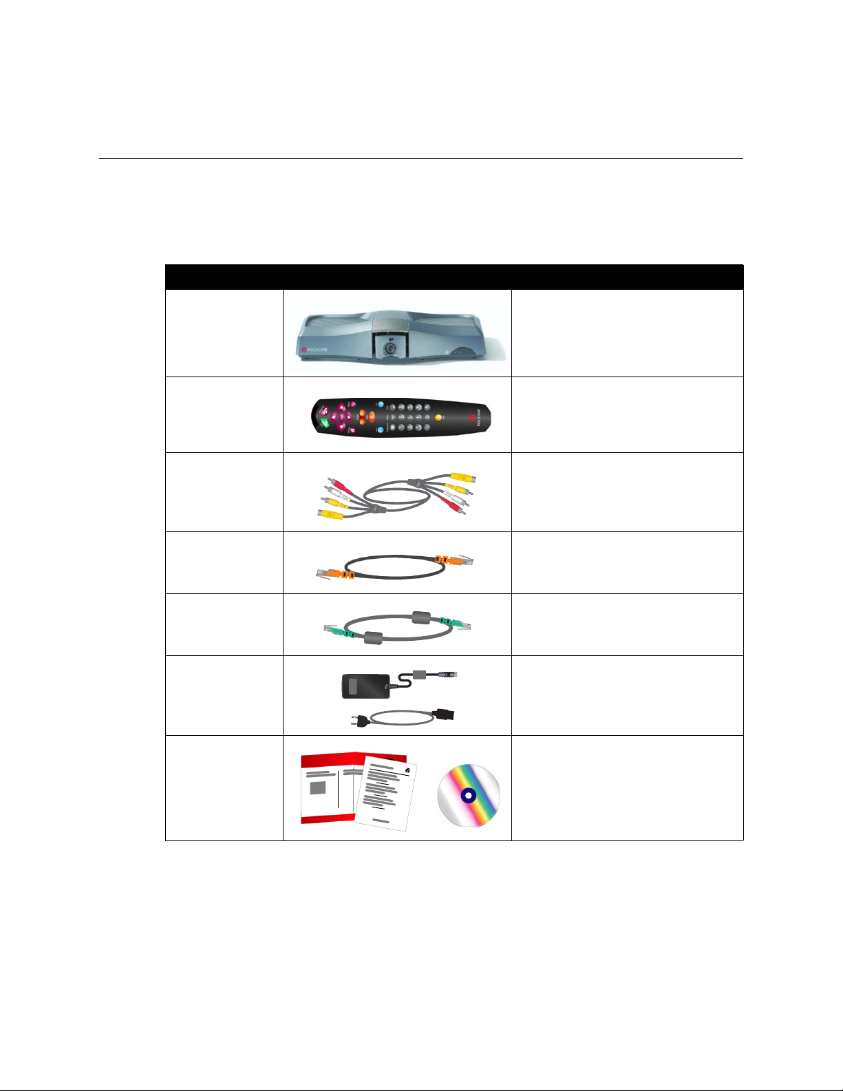
This section describes the standard components that come with the V500 system.
Two models of the V500 system are available — IP only, and IP with ISDN.
Name Component Description
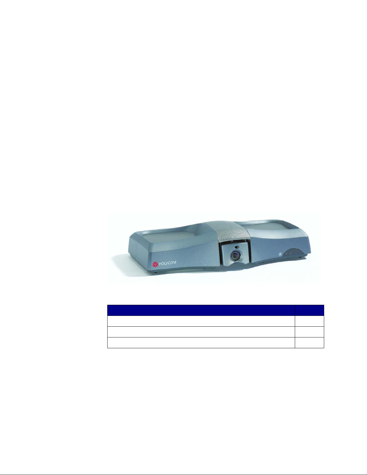
V500 System The V500 system delivers high-quality,
Remote Control The remote control is designed to make
Chapter 1 - Introducing the V500 System
face-to-face video communication in a
sleek package that includes the camera
and microphone.
it easy to set up and operate the system
— color-coded buttons correspond to
system features.
Composite video
cable
LAN cable The LAN cable connects the system to
BRI cable
(IP with ISDN
model only)
Power supply The power supply connects power to
Documentation Read Me First
The composite video cable is a triple
RCA cable with S-video that connects
the V500 system to a monitor.
the IP network.
The BRI cable connects the system to
the ISDN.
the system.
Setting Up the V500 System
V500 system documentation CD
© Polycom, Inc. 1 - 5
Page 14

Administrator’s Guide for the V500 System
Optional System Components
To extend what you do with your V500 system, the following additional options
are available. For information about ordering these options, please see your
Polycom distributor.
❑ Single BRI network interface — Connect the system to use ISDN.
❑ Headphone — Listen privately by adding your own headphone using the
3.5 mm stereo mini jack.
1 - 6 www.polycom.com/videodocumentation
Page 15

2
Setting Up Your System Hardware
This chapter describes how to set up your system with the required components
and optional equipment. If you need additional installation information, refer to
the system setup document that was provided with your system.
For optional components, you can also refer to the setup sheet that was shipped
with the component.
To obtain additional copies of any of these documents, refer to the documentation
CD that came with the system or go to the Polycom web site,
www.polycom.com/videodocumentation.
What’s in this Chapter? Page
Standard System Set-up 2-2
Optional Equipment Set-up 2-6
© Polycom, Inc. 2 - 1
Page 16

Administrator’s Guide for the V500 System
1.
Standard System Set-up
This section describes how to connect the components that are required for the
basic system set-up. Procedures for connecting additional equipment are in the
next section, Optional Equipment Set-up on page 2-6.
Positioning the System
The V500 system is designed for homes, home offices, or small offices.
To position the system:
>> Place the system on top of your monitor. For optimal audio and video
performance, locate the monitor within 5 to 10 feet (1.52 to 3.05 meters) away
from the people in the call.
5'-10'
2 - 2 www.polycom.com/videodocumentation
Page 17
Connecting the Monitor
You must connect a television monitor to the V500 system. This may be an NTSC
or PAL monitor, depending on your system.
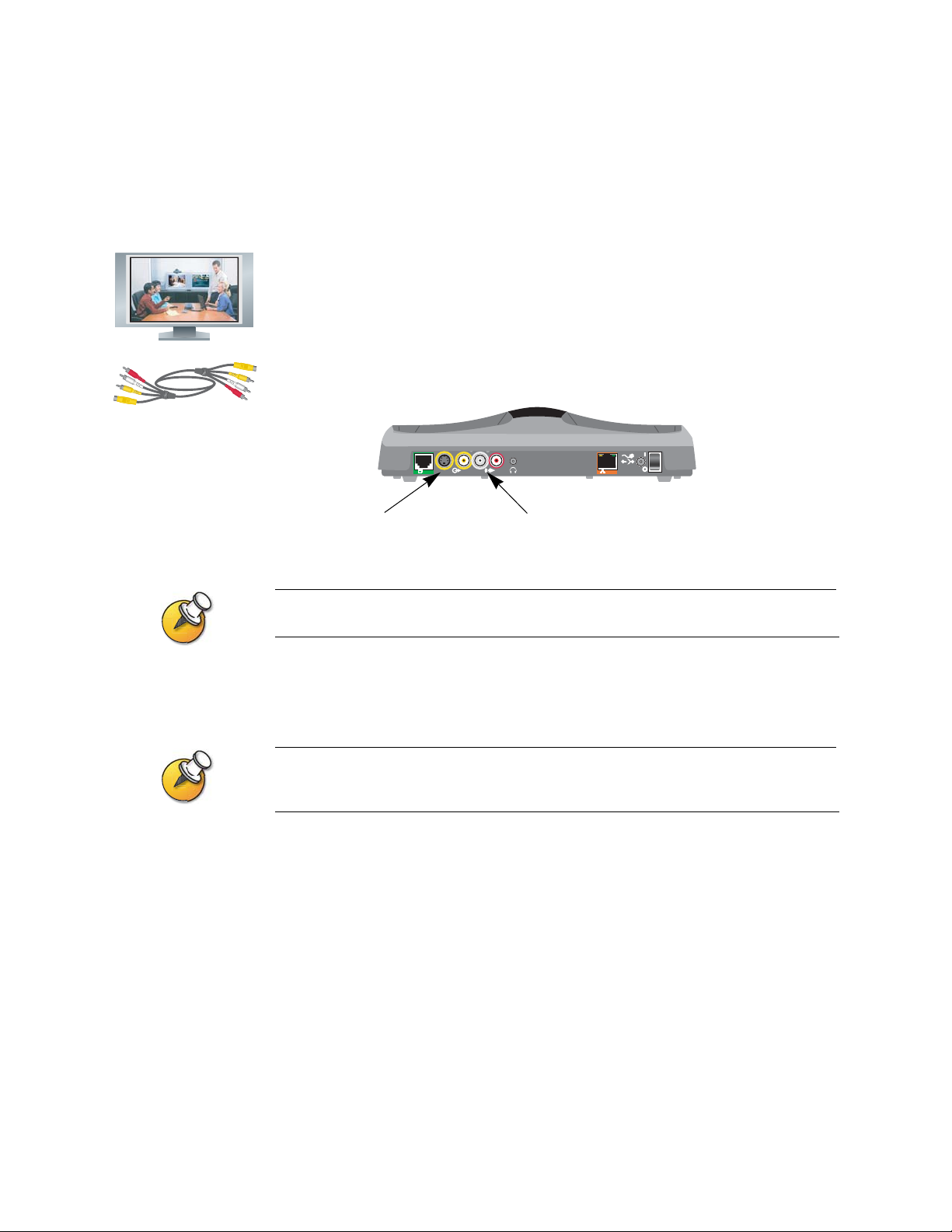
To connect a monitor to the system:
1. Connect the monitor to the S-video or composite video outputs on the back of
the V500 system.
You must use the same type of connector on the monitor as on the system. For
example, if you use the S-video connector on the monitor, use the S-video
connector on the system.
Chapter 2 - Setting Up Your System Hardware
DC IN 12V
BRI
LAN
S-video output
(preferred)
S-video provides superior video quality, and is recommended.
2. Connect the system’s audio outputs to the monitor’s audio inputs using the
red and white connectors on the monitor cable.
After you have finished setting up the system, you will need to configure the monitor’s
behavior. Refer to Configuring the TV Monitor on page 4-7.
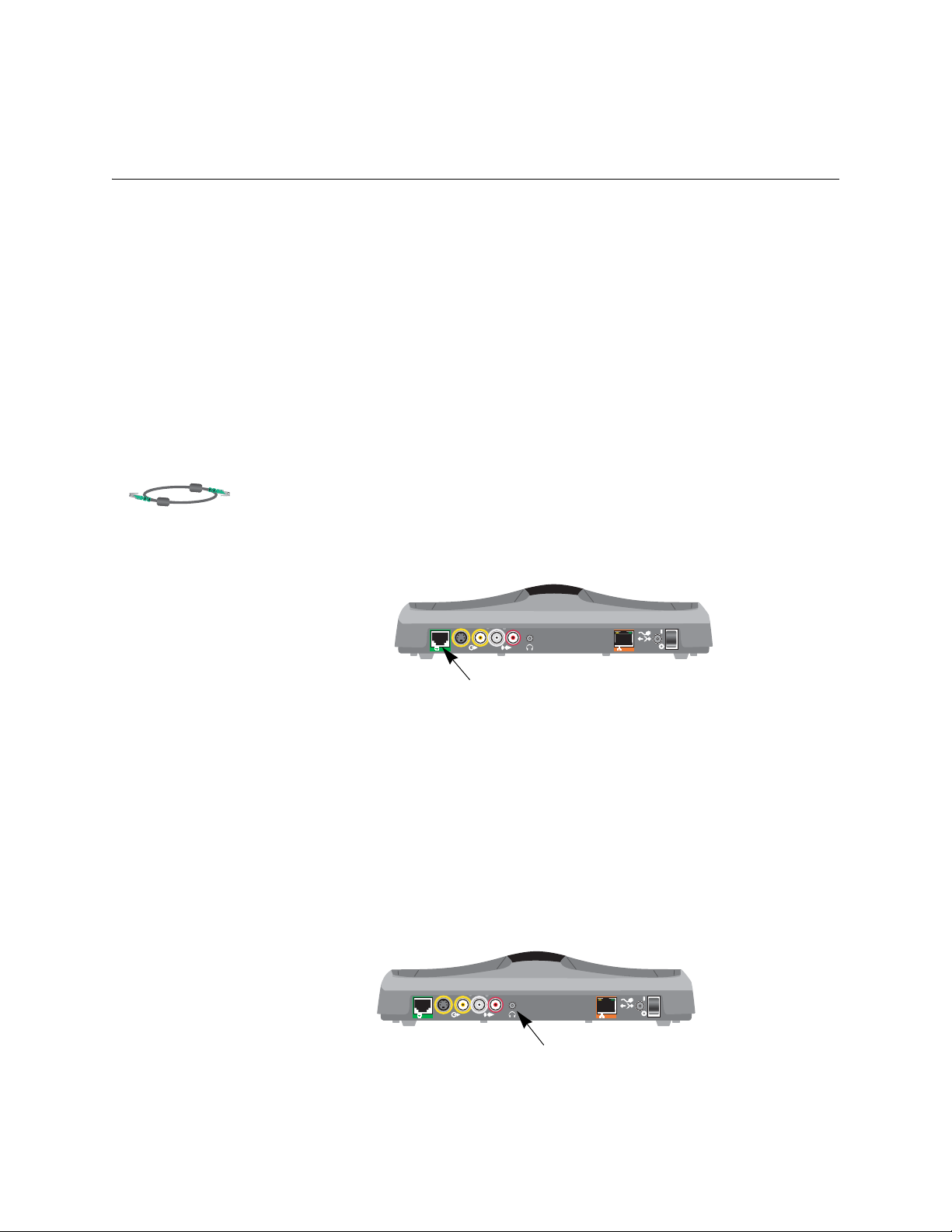
Connecting the System to the LAN
The steps you need to take to connect to the LAN depend on your network
environment. For example, you may have a small office with multiple PCs, a
broadband modem, and a router; you may have a broadband modem and one PC
in your home; or, you may have another type of network environment altogether.
Composite video output
In all cases, you must first connect the LAN to the system with the LAN cable. If
you have a router, gateway, or broadband modem, you must also open the ports
used by the V500 system to access the Internet. Once you have done these, refer to
the section that pertains to your environment.
© Polycom, Inc. 2 - 3
Page 18
Administrator’s Guide for the V500 System
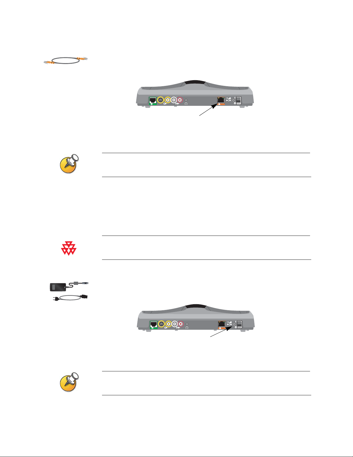
To connect the system to the LAN:
1. Connect the LAN cable to the LAN connector on the back of the system.
2. Connect the other end of the LAN cable to the LAN.
After you have finished setting up the system, you will need to configure it to work properly
in your network. Refer to Configuring Network Use on page 3-1.
Connecting Power
DC IN 12V
BRI
LAN
LAN connector
The V500 system has an external power supply.
Do not use a power supply other than the one supplied with your V500 system. Using the
wrong power supply will void the warranty and may damage your system.
To connect power to the system:
1. Connect the power supply to the power connector on the back of the system.
DC IN 12V
BRI
LAN
Power connector
2. Connect the power cord to the power supply.
Do not connect the V500 system power cord to a wall outlet until you have connected all
equipment to the system.
2 - 4 www.polycom.com/videodocumentation
Page 19

Installing Batteries in the Remote Control
The remote control uses three AAA batteries, which are included with the system.
To install batteries in the remote control:
1. Remove the battery cover from the back of the remote control.
2. Refer to the diagram inside the remote control, and install the batteries in the
orientation shown.
3. Reinstall the battery cover on the remote control.
Powering on the System
After you have connected all your standard and optional equipment, plug the
power cord into a wall outlet.
To power on the system:
Chapter 2 - Setting Up Your System Hardware
>> Press the power switch located at the back of the system.
DC IN 12V
BRI
Power switch
LAN
© Polycom, Inc. 2 - 5
Page 20
Administrator’s Guide for the V500 System
Optional Equipment Set-up
This section describes how to connect optional components to the V500 system.
Connecting to a BRI Network Interface
The V500 system is available with the optional BRI network interface, which
allows you to make ISDN calls.
You may need an NT-1 device if your site does not use an internal telephone
system (PBX). A PBX or an NT-1 device provides the S/T interface that the
system’s BRI network interface requires.
To install the BRI network interface:
1. Make sure the system is powered off.
2. Connect the BRI cable from the BRI connector on the back of the system to
ISDN or to your NT-1 device, as appropriate.
3. If you are using an NT-1 device, connect it to the ISDN.
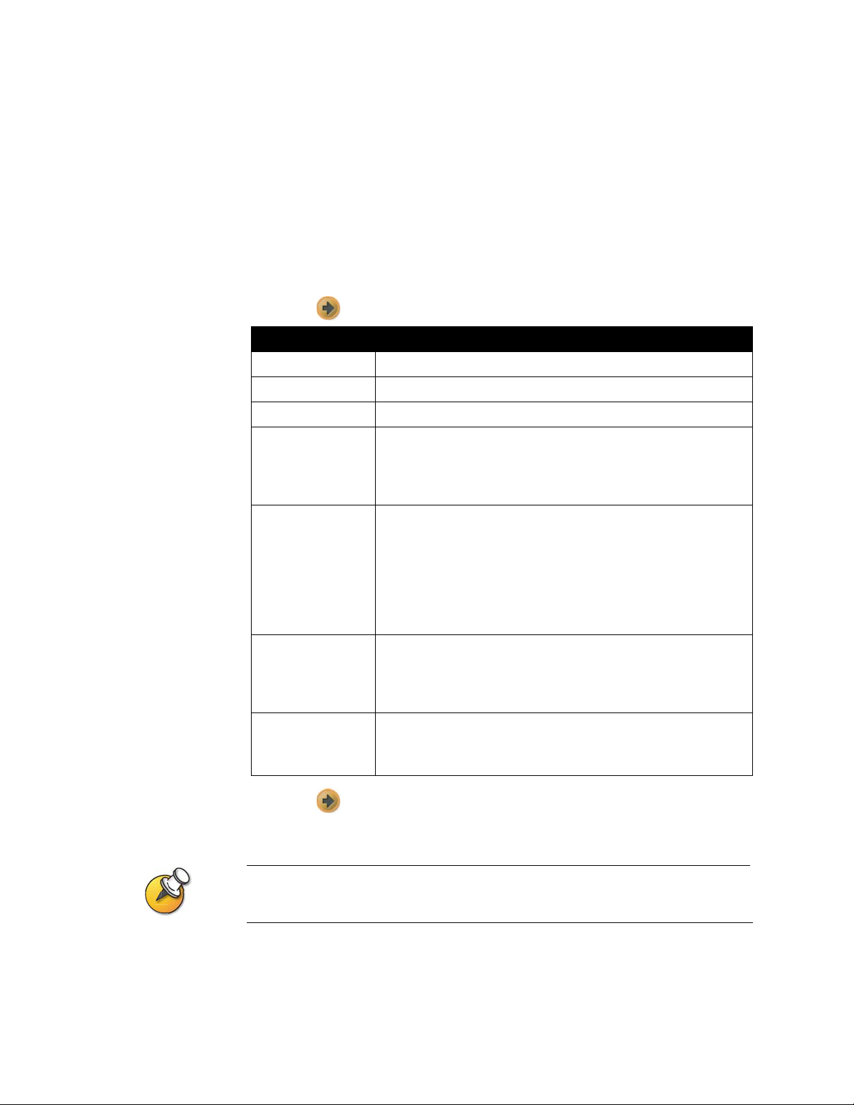
Connecting Headphones
You can connect headphones to the V500 system to listen to your calls privately.
To connect headphones to the system:
>> Connect the headphone cable to the headphone jack on the back of the system.
BRI
BRI connector
BRI
Headphone jack
DC IN 12V
LAN
DC IN 12V
LAN
2 - 6 www.polycom.com/videodocumentation
Page 21

3
Configuring Network Use
This chapter lists the information you need to get your network ready for video
conferencing. Once you’ve gathered that information, you can begin configuring
the system’s network options. Details on how to perform this configuration are
also included in this chapter.
When you power on your system for the first time, the setup wizard detects the
system’s IP and ISDN connections and leads you through the minimum
configuration steps required to place a call.
If you need to change any of the initial settings to accommodate your environment,
you can manually adjust them using the screens described in this chapter.
Note that if you establish an administrator’s password during the setup wizard,
you will need to enter it each time you wish to change advanced settings.
What’s in this Chapter? Page
Getting the Network Ready 3-2
Network Connectivity Checklist 3-2
Configuring with the Setup Wizard 3-3
Configuring LAN Properties 3-4
Configuring IP Network Support 3-6
Configuring ISDN Support 3-13
Configuring Call Preferences 3-14
Configuring the Global Directory 3-16
Placing a Test Call 3-17
Checking System Status 3-18
Keeping your Software Current 3-19
© Polycom, Inc. 3 - 1
Page 22

Administrator’s Guide for the V500 System
Getting the Network Ready
Before you begin configuring the network options, you must make sure your
network is ready for video conferencing.
To begin, refer to the Preparing Your Network for Collaboration document, available
at www.polycom.com/videodocumentation. This document contains information
you need to prepare your network, such as worksheets that will help you order
ISDN.
Network Connectivity Checklist
You may need this information to make and receive video calls at your site:
If: This information: Should be provided by your:
Your system is using a
static IP address
Your network uses a
gatekeeper
Your system is behind a
firewall
You are using BRI ISDN address ISDN Service Provider
You are using ISDN and
are in North America
You are using ISDN ISDN switch protocols ISDN Service Provider
IP address IP Network Service Provider
Gatekeeper address IP Network Service Provider
Firewall information IP Network Service Provider
SPIDs ISDN Service Provider
3 - 2 www.polycom.com/videodocumentation
Page 23

Configuring with the Setup Wizard
When you power on your system for the first time, the setup wizard detects the
system’s IP and ISDN connections and leads you through the minimum
configuration steps required to place a call. If you need more information about
these steps, refer to the corresponding sections in this chapter.
The setup wizard enables you to set an administrator password, which allows you
to limit access to the Admin Settings. The administrator password may contain
letters and numbers, but no other characters.
The default administrator password is the system’s serial number. If you change the
password, make sure you remember it. If you f orget the passw ord, you will hav e to reset the
system, delete the system files, and run the setup wizard again in order to access the Admin
Settings and reset the password. You cannot set the administrator password from a remote
location.
You can run the setup wizard or view the configuration screens in either of these
two ways.
Chapter 3 - Configuring Network Use
❑ In the room with the system — Use the remote control to navigate the screens
and enter information. You can use the number pad on the remote control to
enter text just like you can with a cell phone.
❑ From a remote location — Use a web browser to access the V500 web interface.
To do this, you need to know the IP address of the system. Polycom
recommends using Microsoft® Internet Explorer 6.0 or later.
You can use the web interface to configure all of the system settings except the remote
management settings, which must be configured on the local system.
To access the system via the V500 web interface:
1. On a PC, open a web browser.
2. In the browser address line, enter the IP address of the system (for example,
http://255.255.255.255) to go to the V500 web interface.
3. Enter your user name and the password, if a password has been established.
© Polycom, Inc. 3 - 3
Page 24

Administrator’s Guide for the V500 System
Configuring LAN Properties
If your system is part of a LAN, use this section to configure the system to work
with the LAN.
Before you Begin
If you are connecting the system via a modem, you need to request an additional
public IP address from your Internet service provider.
Your service provider will provide you with one of these IP addresses:
❑ Static IP address – The address is reserved for your system and will not
change. When you configure the LAN properties of the system, choose the
Enter IP Address Manually option.
Your service provider should also provide you with the DNS server address,
default gateway address, subnet mask, and WINS server IP address.
❑ Dynamic IP address – The address is obtained from your service provider’s
DHCP server, and therefore may change. When you configure the LAN
properties of the system, choose the Obtain IP Address Automatically option.
To configure LAN properties:
1. Go to System > Admin Settings > LAN Properties.
2. Configure these settings:
Setting Description
Connect to my LAN Specifies whether the system is part of the LAN.
Allow IP Calls Enables the system to make and receive IP calls.
Host Name Indicates the system’s DNS name.
If you change the Host Name, the system restarts.
IP Address Specifies how the system obtains an IP address.
• Obtain IP Address Automatically — Select if the system gets
an IP address from the DHCP server on the LAN.
• Enter IP Address Manually — Select if the IP address will not
be assigned automatically.
Your IP Address is
or
Use the Following
IP Address
If the system obtains its IP address automatically, this area
displays the IP address currently assigned to the system.
If you selected Enter IP Address Manually, enter the IP address
here.
3 - 4 www.polycom.com/videodocumentation
Page 25

Chapter 3 - Configuring Network Use
Setting Description
Domain Name Displays the domain name currently assigned to the system.
If the system does not automatically obtain a domain name, enter
one here.
DNS Servers Displays the DNS servers currently assigned to the system.
If the system does not automatically obtain a DNS server address,
enter up to four DNS servers here.
Default Gateway Displays the gateway currently assigned to the system.
If the system does not automatically obtain a gateway IP address,
enter one here.
Subnet Mask Displays the subnet mask currently assigned to the system.
If the system does not automatically obtain a subnet mask, enter
one here.
WINS Server Displays the WINS server currently assigned to the system.
If the system does not automatically obtain a WINS server IP
address, enter one here.
WINS Resolution Sends a request to the WINS server for WINS name resolution.
LAN Speed Specify the LAN speed to use. Note that the speed you choose
must be supported by the switch.
Choose Auto to have the network switch negotiate the speed
automatically. If you choose 10 Mbps or 100 Mbps, you must also
select a duplex mode.
Duplex Mode Specify the Duplex mode to use. Note that the Duplex mode you
choose must be supported by the switch.
Choose Auto to have the network switch negotiate the Duplex
mode automatically.
© Polycom, Inc. 3 - 5
Page 26

Administrator’s Guide for the V500 System
Configuring IP Network Support
Use the following sections to configure the system so that you can place and
receive video calls using IP on your LAN or WAN:
❑ H.323 Settings, including Gatekeeper and Gateway
❑ SIP Settings
❑ Quality of Service
❑ Firewall or NAT
Specifying H.323 Settings
If your network uses a gatekeeper, the system can automatically register its H.323
name and extension. This allows others to call the system by entering the H.323
name or extension instead of the IP address.
To specify H.323 settings:
1. Go to System > Admin Settings > Network > IP > H.323 Settings.
2. Configure these settings:
Setting Description
Enable IP H.323 Specifies whether to allow IP dialing.
Display H.323
Extension
H.323 Name Specifies the name that gatekeepers and gateways use to identify
H.323 Extension
(E.164)
Lets you place a gateway call by entering the H.323 extension
separately from the gateway ID.
If you do not check this box, you can make gateway calls by
entering the call information in this format:
gateway ID + TCS4 delimiter + extension
Check with your network provider to determine your TCS4
delimiter.
this system. You can make point-to-point calls using H.323 names
if both systems are registered to a gatekeeper.
The H.323 Name is the same as the System Name, unless you
change it. Your dial plan may define the names you can use.
Lets you place point-to-point calls using the extension if both
systems are registered with a gatekeeper.
The default H.323 Extension is based on the system serial
number, but it can be change d. Your dial plan may define the
extensions you can use.
3 - 6 www.polycom.com/videodocumentation
Page 27

Configuring the System to Use a Gatekeeper
A gatekeeper supervises network traffic and manages functions such as
bandwidth control and admission control. The gatekeeper also handles address
translation, which allows you to make calls using static aliases instead of IP
addresses that may change each day.
To configure the system to use a gatekeeper:
1. Go to System > Admin Settings > Network > IP > H.323 Settings.
2. Select and configure these settings:
Setting Description
Use Gatekeeper Specifies whether to use a gatekeeper. Gateways and
gatekeepers are required for calls between ISDN and IP networks.
• Off — Calls do not use a gatekeeper.
•Auto — System automatically finds an available gatekeeper.
• Specify — Calls use the specified gatekeeper. Enter the
gatekeeper’s IP address or name (for example,
gatekeeper.companyname.usa.com or 255.255.255.255).
Chapter 3 - Configuring Network Use
H.323 Name Specifies the name that gatekeepers and gateways use to identify
this system. You can make point-to-point calls using H.323 names
if both systems are registered to a gatekeeper.
The H.323 Name is the same as the System Name, unless you
change it. Your dial plan may define the names you can use.
H.323 Extension
(E.164)
Outbound Call
Route
Gatekeeper IP
Address
Alternate
Gatekeepers
Lets you place point-to-point calls using the extension if both
systems are registered with a gatekeeper.
The default H.323 Extension is based on the system serial
number, but it can be change d. Your dial plan may define the
extensions you can use.
For systems using a gatekeeper, specifies whether calls initiated
by this system should be handled as IP calls sent through a
gateway or as ISDN.
If you chose to use an automatically selected gatekeeper, this
area displays the gatekeeper’s IP address.
If you chose to specify a gatekeeper, enter the IP address here.
If you chose to specify a gatekeeper, you can specify other
gatekeepers that the system can use if the primary gatekeeper is
not available.
© Polycom, Inc. 3 - 7
Page 28
Administrator’s Guide for the V500 System
Configuring the System to Use a Gateway
A gateway performs code and protocol conversion between IP networks and
ISDN, so that users on different networks can call one another. If the system is
configured to use a gateway, you must also configure it to use a gatekeeper.
To configure the system to use a gateway:
1. Go to System > Admin Settings > Network > IP > H.323 Settings.
2. Select twice and configure these settings:
Setting Description
Country Code Specifies the country code for the system’s location.
Area Code Specifies the area or city code for the system’s location.
Number Specifies the gateway’s number.
H.323 Extension
(E.164)
Gateway Number
Type
Number of Digits in
DID Number
Number of Digits in
Extension
Lets you place point-to-point calls using the extension if both
systems are registered with a gatekeeper.
The default H.323 Extension is based on the system serial
number, but it can be changed.
Specifies the number type users enter to call this system:
• Direct Inward Dial (DID) — Users enter an internal extensi on
to call this system directly.
NOTE: If you choose this option, you must also register the
number with the gatekeeper as an E.164 alias.
• Number + Extension — Users enter the gateway number and
the system’s extension to call this system.
Specifies the number of digits in the DID number.
The national or regional dialing plan for your location determines
the standard number of digits. For instance, the US standard is 7
digits.
Specifies the number of digits in the extension used when
Number + Extension is selected.
Your organization’s dial plan determines this number.
3. Select and enter a prefix or suffix for each bandwidth you want to allow
for gateway calls.
Be sure to configure the gateway to use the same prefixes and suffixes you define for the
system.
3 - 8 www.polycom.com/videodocumentation
Page 29

Specifying SIP Settings
If your network supports the Session Initiation Protocol (SIP), you can use SIP to
connect IP calls.
To specify SIP Settings:
1. Go to System > Admin Settings > Network > IP > SIP Settings.
2. Configure these settings:
Setting Description
Enable SIP Allows the system to make calls using SIP.
Transport Protocol Indicates the protocol the system uses for SIP signalling.
Chapter 3 - Configuring Network Use
The SIP network infrastructure in which your V500 system is
operating determines which protocol is required. For example, if
your V500 system is operating in a Microsoft Live Communication
Server (LCS) SIP network, choose TCP. If your V500 system is
operating in a Nortel Multimedia Communication Server (MCS)
SIP network, choose UDP.
Password Specifies the password that authenticates the system to the
Registrar Server.
User Name Specifies the system’s SIP name. If you leave this field blank, the
system’s IP address is the SIP user name.
Proxy Server Specifies the DNS name or IP address of the SIP Proxy Server. If
you leave this field blank, no proxy server is used.
By default, the SIP signalling is sent to port 5060 on the proxy
server. To specify a different port, add it to the address as shown
here:
255.255.255.255:5070
Registrar Server Specifies the name or IP address of the SIP Registrar Server.
By default, the SIP signalling is sent to port 5060 on the registrar
server. To specify a different port, add it to the address as shown
here:
255.255.255.255:5070
© Polycom, Inc. 3 - 9
Page 30

Administrator’s Guide for the V500 System
Specifying Quality of Service
Set the Quality of Service options for the way your network handles IP packets
during video calls.
To specify Quality of Service:
1. Go to System > Admin Settings > Network > IP > Quality of Service.
2. Configure these settings:
Setting Description
Type of Service Specifies your service type and lets you choose how to set the
priority of IP packets sent to the system for video, audio, and
far-end camera control:
• IP Precedence — Represents the priority of IP packets sent to
the system. The value can be between 0 and 5. If this option is
selected, enter the value in the Type of Service Value field.
• DiffServ — Represents a priority level between 0 and 63. If this
option is selected, enter the value in the Type of Service Value
field.
Type of Service
Value
Enable PVEC Allows the system to use PVEC (Polycom Video Error
Dynamic
Bandwidth
Maximum Transmit
Bandwidth
Maximum Receive
Bandwidth
If the system is connected to the Internet via DSL or a cable modem, it is useful to set
maximums for transmitting and receiving bandwidth. DSL and cable modems typically allow
for faster download (receive) speeds compared to upload (transmit) speeds, and so these
settings provide an opportunity to regulate differences.
Specifies the IP Precedence or Diffserv value for Video, Audio,
and Far-End Camera Control.
Concealment) if packet loss occurs.
Specifies whether to let the system automatically find the optimum
line speed for a call.
Specifies the maximum transmit line speed between 48 Kbps and
512 Kbps.
Specifies the maximum receive line speed between 48 Kbps and
512 Kbps.
3 - 10 www.polycom.com/videodocumentation
Page 31

Chapter 3 - Configuring Network Use
Configuring the System for Use with a Firewall or NAT
A firewall protects your network by controlling data traffic from outside the
network. Unless the firewall is designed to work with H.323 video conferencing
equipment, you must configure the system and the firewall to allow video
conferencing traffic to pass in and out of the network.
Network Address Translation (NAT) network environments use private internal IP
addresses for devices within the network, while using one external IP address to
allow devices on the LAN to communicate with other devices outside the LAN. If
yo ur syst em is connec ted t o a LA N that u ses a NAT, you will need to ent er th e NAT
public (WAN) address so that your system can communicate outside the LAN.
To set up the system to work with a firewall or NAT:
1. Go to System > Admin Settings > Network > IP > Firewall.
2. Configure these settings:
Setting Description
Fixed Ports Lets you specify whether to define the TCP and UDP ports.
• If the firewall is not H.323 compatible, enable this option. The
V500 system assigns a range of ports starting with the TCP
and UDP ports you specify. The system defaults to a range
beginning with port 3230 for both TCP and UDP.
NOTE: You must open the corresponding ports in the
firewall. You must also open the firewall’ s TCP port 1720 to
allow H.323 traffic.
• If the firewall is H.323 compatible or if the system is not
behind a firewall, disable this option.
TCP Ports
UDP Ports
© Polycom, Inc. 3 - 11
Lets you specify the beginning value for the ra nge of TCP and
UDP ports used by the system.
NOTE: You must also open the firewall’s TCP port 1720 to
allow H.323 traffic.
Page 32

Administrator’s Guide for the V500 System
Setting Description
NAT Configuration Lets you specify whether the system should determine the
NAT Public WAN Address automatically.
• If the system is behind a NA T that allows HTTP traffic, select
Auto.
• If the system is behind a NAT that does not allow HTTP
traffic, select Manual.
• If the system is not behind a NAT or is connected to the IP
network through a Virtual Private Network (VPN), select Off.
• If the system is behind a firewalled NAT router that is
UPnP™ (Universal Plug and Play) certified, select UPnP.
Many routers used in homes and small businesses support
UPnP NAT traversal. If this is your situation, try selecting
UPnP first. If this selection does not work for your router,
select Auto or Manual.
NAT Public (WAN)
Address
Displays the address that callers from outside the LAN use to
call your system. If you chose to configure the NAT manually,
enter the NAT Public Address here.
NAT is H.323
Compatible
Address Displayed in
Global Directory
Specifies that the system is behind a NAT that allows HTTP
traffic.
Lets you choose whether to display this system’s public or
private address in the Global Directory.
Configure the V500 system for specific products as follows:
If you use this type of
NAT or firewall: Configure your V500 system this way:
Use Fixed Ports System is
Behind a NAT
Cisco® PIX
NOTE: Do not select the
Fix Up H.323 feature.
Cisco® Router NAT No No No
Linksys
Netgear
SMC® Barricade™ Yes Yes No
®
®
®
Yes Yes No
Yes Setting is ignored No
No No Yes
NAT is H.323
Compatible
Systems deployed outside a firewall are potentially vulnerable to unauthorized access. Visit
the Polycom Security Center at www.polycom.com for timely security information. You can
also register to receive periodic email updates and advisories.
3 - 12 www.polycom.com/videodocumentation
Page 33

Configuring ISDN Support
The V500 system supports the BRI network interface for ISDN calling.
The system automatically detects the type of interface installed and displays only
the required configuration screens.
Configuring the BRI Network Interface
To configure the ISDN interface settings:
1. Go to System > Admin Settings > Network > ISDN.
2. Configure these settings:
Setting Description
Enable ISDN H.320 Allows this system to make H.320 (ISDN) calls.
Chapter 3 - Configuring Network Use
Outside Line
Dialing Prefix
ISDN Switch
Protocols
ISDN Voice
Algorithm
Auto BRI
Configuration
Specifies the ISDN dialing prefix used to call outside the network.
Specifies the protocol used by your network’s switch.
Specifies which voice algorithm (Alaw or uLaw) is used for ISDN
voice calls.
Do not change this setting unless you experience audio issues in
all ISDN voice calls.
Allows the NI-1 switch to automatically configure the directory
numbers and SPIDs.
This setting is only available if you have selected the NI-1 switch
protocol.
© Polycom, Inc. 3 - 13
Page 34

Administrator’s Guide for the V500 System
3. Select and configure these settings:
Setting Description
Area Code Specifies the area code for this system’s location.
Directory Numbers Specifies the numbers assigned to the B1 and B2 channels for the
Enable Specifies whether to enable the ISDN line.
The ISDN BRI Numbers screen also displays the country selected as the
system’s location and the Country Code used for international calls to the
system. To specify the system’s location, go to System > Admin Settings >
General Settings > Location. The system automatically supplies the country
code when you specify the country.
BRI line.
The two numbers for a line may be the same or different,
depending on the switch protocol in use.
If you selected the Standard ETSI Euro ISDN protocol, you must
enable the BRI line.
4. If you have configured
the ISDN switch protocol to be AT&T 5ESS Multipoint,
NI-1, or Nortel DMS-100, select and enter the ISDN BRI SPIDs provided
by your service provider.
After you enter the SPIDs, the system verifies them. If the system is unable to
verify the SPIDs, make sure the system is connected and that the ISDN
numbers you entered are correct.
If you do not have the SPIDs from your service provider, you can click Start to
Auto-Detect SPIDs.
Configuring Call Preferences
Call preferences help you manage the network bandwidth used for calls. You can
specify the default and optional call settings for outgoing calls. You can also limit
the call speeds of incoming calls.
To choose call preferences:
1. Go to System > Admin Settings > Network > Call Preference.
3 - 14 www.polycom.com/videodocumentation
Page 35

Chapter 3 - Configuring Network Use
2. Configure these settings:
Setting Description
Enable H.329 Specifies standards-based People + Content data collaboration.
Enable IP H.323 Allows the system to make IP calls.
Enable SIP Allows the system to use SIP when connecting IP calls.
Enable ISDN H.320 Allows the system to make ISDN calls.
Enable Voice Over
ISDN
Allows the system to make voice-only calls to phones connected
to an ISDN network, such as an organization’s PBX.
3. Select to go to the Network Dialing screen and specify the dialing order
preference between IP and ISDN.
If the sites in your directory have both IP and ISDN numbers, these settings determine
your network preferences for placing the call.
4. Select to go to the Preferred Speeds screens and configure these settings:
Setting Description
Preferred Speed for
Placing Calls
Maximum Speed
for Receiving Calls
Determines the speeds that will be used for calls from this system
when:
• Call Quality is set to Auto on the home screen and Directory
screen
• The Call Quality option is not available for users
If the far-end system does not support this quality, the system
automatically negotiates a lower quality.
Allows you to restrict the bandwidth used when receiving calls.
If the far site attempts to call the system at a higher speed than
selected here, the call is re-negotiated at the speed specified in
this field.
5. Select to go to the Call Speeds screen and specify the call speeds to make
available to users, if you are allowing them to choose speeds on a call-by-call
basis.
© Polycom, Inc. 3 - 15
Page 36

Administrator’s Guide for the V500 System
Configuring the Global Directory
If you use the Polycom Global Management System, you can configure your
system to use the Global Directory. The Global Directory provides a list of other
systems that are registered with the Global Directory Server and are available for
calls. The other systems appear in the Directory, allowing you to place calls to other
users by selecting their names.
Configuring the Directory Server Settings
To configure the Directory Server settings:
1. Go to System > Admin Settings > Global Services > Directory Servers.
2. Configure these settings:
Setting Description
Global Directory
(GDS)
Register Registers this system with the Global Directory Server.
Password Lets you enter the Global Directory password, if there is one.
Display Global
Addresses
Display Name in
Global Directory
Save Global
Directory to System
Specifies the IP address or DNS address of the Global Directory
Server. You can enter up to five addresses.
Displays other registered systems in the Global Directory.
Specifies whether to display the system’s name in the Global
Directories of other registered systems.
Copies the Global Directory to this local system.
3 - 16 www.polycom.com/videodocumentation
Page 37

Setting the Dialing Rules
If your system is connected to a private network and also to a public network, you
may need to specify the codes and prefixes necessary for dialing other systems.
To set the dialing rules:
1. Go to System > Admin Settings > Global Services > Dialing Rules.
2. Configure these settings:
Setting Description
Chapter 3 - Configuring Network Use
Always Dial Area
Code
Dial 1+ for all USA
calls
Placing a Test Call
When you finish configuring the system, you can use one of the sample numbers
in the directory to test your setup.
To place a test call:
1. On the Place a Call screen, select .
2. Select Category.
3. Select Sample Sites and highlight a location.
4. Press on the remote control.
Specifies that calls to sites in the same area code must include
the area code.
Specifies that calls to systems in the United States must include
a “1” before the area code.
You can also find a list of worldwide numbers that you can use to test your V500 system at
www.polycom.com/videotest.
© Polycom, Inc. 3 - 17
Page 38

Administrator’s Guide for the V500 System
If you have trouble making video calls:
❑ Make sure the number you dialed is correct, then try the call again. For
example, you may need to dial 9 for an outside line or include a long distance
access code or country code.
❑ To find out if the problem exists in your system, ask the person you were trying
to reach to call you instead.
❑ Find out if the system you are calling has its power turned on and is
functioning properly.
❑ If you can make calls but not receive them, make sure that your system is
configured with the correct number.
Checking System Status
The System Status screen provides detailed information about system settings, IP
and ISDN connections, time server connections, and other information that is
important to the functioning of the system. For an explanation of any of the status
items, select the item and press on the remote.
When there is a change in system status or a potential problem, you see an alert at
the bottom of the Place a Call screen.
To view System Status information:
>> Go to System > Diagnostics > System Status.
To get information about a status message:
>> Select the status message and press or on the remote control.
3 - 18 www.polycom.com/videodocumentation
Page 39

Keeping your Software Current
If you have Internet access, you can use the web-based Softupdate application to
upgrade the system software. If you do not have Internet access, your reseller can
supply you with the updated software on CD-ROM.
Before you begin, read the Release Notes, available at www.polycom.com/videosoftware,
for the latest information about this software version.
To upgrade your software via the Internet:
1. From your PC, go to www.polycom.com/videosoftware.
2. Log in to the Polycom Product Resource Center, find your product page, and
download the software update file in .zip format.
3. Double-click the software.zip file to extract the file.
Chapter 3 - Configuring Network Use
4. Double-click Softupdate.exe.
5. Click Softupdate, then enter the IP address of the system you want to update.
Enter the administrator password, if required, and click OK to begin the
upgrade.
6. On the Options tab of the Softupdate application, select the other actions you
want to occur during the update:
• Remove Address Book — Check this option to delete your existing
directory before the update.
• Remove System Files — Check this option to delete your existing system
files before installing new system files.
7. Click Continue to upgrade the software.
Caution
Do not power off the system during the software upgrade process. If the upgrade is
interrupted, the system reverts to its original software version.
© Polycom, Inc. 3 - 19
Page 40

Administrator’s Guide for the V500 System
3 - 20 www.polycom.com/videodocumentation
Page 41

4
Designing the User Experience
Everybody who uses the Polycom V500 system has different needs. That’s why
your system has a customizable user interface. You can design the video
conferencing experience to meet your needs and the needs of any other users who
use the system.
You can customize the behavior of the system, and then build in various access
levels for the different users, depending on how much or how little you want them
to change system behaviors.
When you set up the system for the first time, the system is configured with the
most commonly used settings. If you need to change any of these initial settings,
you can adjust the screen settings as described in this chapter.
If you established an administrator’s password during the initial configuration,
you must enter it each time you change advanced settings.
What’s in this Chapter? Page
Managing User Access to Settings and Features 4-2
Designing Video Behaviors 4-6
Designing General System Behaviors 4-11
Customizing the Workspace Appearance 4-16
Configuring Closed Captioning 4-22
Getting Started with Calling 4-25
© Polycom, Inc. 4 - 1
Page 42

Administrator’s Guide for the V500 System
Managing User Access to Settings and Features
You can manage access to various settings and features by using passwords and by
configuring the system to show only those options you want other users to see.
To maintain this
security level: You can allow users to:
High
(Kiosk mode)
Medium Place calls using the restrictions you specify for length of call,
Low Configure user settings.
Very low Configure all system settings.
Setting the Admin Password
Set an administrator’s password to restrict who can:
❑ Make changes other than those in the User Settings screen
❑ Update the software
❑ Perform remote management using the V500 web interface
Call only the numbers you specify on the home screen.
See Using the System for Specialized Applications on
page 4-5 and Designing the Home Screen on page 4-17.
type of call, and use of the directory.
See Limiting What Users Can Do With the System on
page 4-5.
See Letting Users Customize the Workspace on page 4-4.
To set or change the Admin Password:
1. Go to System > Admin Settings > General Settings > Security.
2. Enter or change the password. You may use letters and numbers, but no other
characters.
4 - 2 www.polycom.com/videodocumentation
Page 43

Chapter 4 - Designing the User Experience
To reset a forgotten Admin Password:
1. Get the system’s serial number from the system or from the System
Information screen.
2. Go to System >Diagnostics > Reset System.
3. Enter the system’s serial number and select Delete System Settings.
4. Select Reset System.
When the system completes the reset, it leads you through the setup wizard. You
can enter a new Admin Password when you set up the system.
Screens that Require the Admin Password for Access
The following diagram shows top-level system screens. All screens within Admin
Settings require the administrator’s password.
Admin Settings Diagnostics
General Settings Network LAN PropertiesAudioCameraMonitor Global Services
System Settings
Home Screen Settings
Security
Location
IP
ISDN
Call Preference
Recent Calls
H.323 Settings
SIP Settings
Quality of Service
Firewall
System Information Utilities
User Settings
Directory Servers
Dialing Rules
SNMP
Management Servers
Account Validation
My Information
© Polycom, Inc. 4 - 3
Page 44

Administrator’s Guide for the V500 System
Letting Users Customize the Workspace
You can allow other users of the V500 system to change common user preferences
by providing access to the User Settings screen.
To allow users to customize the workspace:
1. Go to System > Admin Settings > General Settings > Security.
2. Check the Allow Access to User Settings option to make the User Settings
button available to users on the System screen.
User Settings contains the following options:
❑ Backlight Compensation
❑ Camera Brightness
❑ Meeting Password
❑ Auto-Answer Point to Point
❑ Mute Auto-Answer Calls
❑ PIP
❑ Keypad Audio Confirmation
❑ Color Scheme
❑ Far Site Name Display Time
❑ Dual Monitor Emulation
❑ Allow Video Display on Web
These options are also available to the administrator on the Admin Settings screens.
4 - 4 www.polycom.com/videodocumentation
Page 45

Limiting What Users Can Do With the System
You can limit what you allow other users to do with the system by configuring the
following:
❑ Maximum Time in Call — If you want to specify the maximum time a call can
last, go to System > Admin Settings > General Settings > System Settings >
Call Settings and enter the maximum call length allowed.
❑ Allow Directory Changes — If you do not want anyone to save changes to the
local directory of the system, go to System > Admin Settings > General
Settings > System Settings > Directory and clear this option.
Using the System for Specialized Applications
You can customize the system to show only a specific set of numbers to call. This
mode, also known as “kiosk mode,” can be used for specialized applications, such
as customer query stations or systems used for calling the same numbers on a
regular basis. Kiosk mode requires little or no training and instructions can be
incorporated into the screen design.
Chapter 4 - Designing the User Experience
See Designing the Home Screen on page 4-17 for more details about the kiosk
mode and its applications.
© Polycom, Inc. 4 - 5
Page 46

Administrator’s Guide for the V500 System
Designing Video Behaviors
You can configure the following video behaviors to accommodate your
environment:
❑ Camera Settings
❑ TV Monitor
❑ Dual Monitor Emulation
❑ Monitor’s Color Balance
Configuring Camera Settings
The Camera screen lets you specify camera settings.
To configure camera settings:
1. Go to System > Admin Settings > Camera.
2. Configure these settings:
Setting Description
Backlight
Compensation
Camera
Brightness
Specifies whether to have the camera automatically adjust for a
light background. Backlight compensation is best used in
situations where the subject appears darker than the background.
Specifies how much light is let into the camera’s iris. A low n umber
allows in less light; a high number allows in more light.
4 - 6 www.polycom.com/videodocumentation
Page 47

Configuring the TV Monitor
The V500 system allows you to customize the display to suit your room and
equipment configuration.
To configure the TV monitor:
1. Go to System > Admin Settings > Monitor.
2. Configure these settings:
Setting Description
Monitor Specifies the monitor’s aspect ratio:
Chapter 4 - Designing the User Experience
•4:3 — Select if you are using a regular TV monitor.
•16:9 — Select if you are using a wide screen monitor and
configuring for dual-monitor emulation.
You can set a wide-screen monitor to 16:9 to resize the UI screens
even if you do not configure it for dual-monitor emulation. The
far-site video is displayed in the same way for both settings.
NOTE: If you select 16:9, you will also need to set up the monitor for
full-screen display. In the monitor’s setup menu, choose the setting
that stretches the picture uniformly without clipping the edges.
Use this setting: Not this setting:
PIP Specifies PIP (Picture-in-Picture) behavior:
•On — The PIP window stays on for the duration of the call.
•Off — The PIP window is not displayed during the call.
•Auto — The PIP window is displayed when a user picks up the
remote.
NOTE: PIP settings are also available in the User Settings screen.
Users can turn the PIP on or off and change its location on the
screen using the PIP button on the remote control.
Display Icons in a
Call
Snapshot
Timeout
Dual Monitor
Emulation
Specifies whether to display all on-screen graphics, including icons
and help text, during calls.
Lets you choose whether to have snapshots time out after a period
of four minutes, after which the system returns to live video.
If you want to return to live video before four min utes hav e elapsed,
press the Near button on the remote control twice.
Specifies whether both sites are displayed in a split-screen mode
when using one monitor.
© Polycom, Inc. 4 - 7
Page 48

Administrator’s Guide for the V500 System
Using Dual Monitor Emulation
With Dual Monitor Emulation, you see both near and far sites on one monitor in two
different views. During presentations, you see content and the near and far site s.
Setting Up On the monitor’s setup menu, select the full-screen setting that
Using in a Call
Near and far site are the same size
and appear side by side.
stretches the picture uniformly, without clipping.
On the TV Monitor screen:
1. If you are using a wide screen monitor, set Monitor to 16:9.
Otherwise, set Monitor to 4:3.
2. Select Dual Monitor Emulation.
Call connects
Far site Near site
Near site presses PIP
Size of far site window increases.
Far site presents to near site
Content, near site, and far site are displayed in
dual monitor emulation mode.
4 - 8 www.polycom.com/videodocumentation
Page 49

Adjusting the Monitor’s Color Balance
In most cases, the monitor you connect to your system provides natural color
without any adjustment. Depending on your environment as well as the model of
monitor, however, the video may exhibit one of these problems:
❑ Picture is too dark
❑ Colors appear faded
❑ Picture has too much of one color — for example, the picture may appear
greenish
If you notice any of these, the monitor needs to be adjusted.
To adjust the monitor for natural color:
1. Go to System > Diagnostics > Video.
2. Select the Color Bars icon to display the color bar test screen.
3. Adjust the color using the monitor’s controls for color, contrast, and
brightness. Your monitor may also have controls for tint and temperature.
Chapter 4 - Designing the User Experience
4. When the colors look right on the test screen, press the Near button on the
remote control to stop the Color Bars test and show video of the room.
5. If the color appears natural, you do not need to make further adjustments.
If the color still needs adjustment, use the monitor’s controls to make small
adjustments until the picture appears natural.
Designing Audio Behaviors
This section describes how to configure the audio behaviors of the V500 system,
including:
❑ General Audio Settings
❑ Volume on an External Audio System
© Polycom, Inc. 4 - 9
Page 50

Administrator’s Guide for the V500 System
Configuring General Audio Settings
To configure general audio settings:
1. Go to System > Admin Settings > Audio.
2. Configure these settings:
Setting Description
Master Audio V olume Sets the volume level for audio from the far site.
Sound Effects
Volume
Incoming Video Call Specifies the ring tone used for incoming calls.
User Alert Tones Specifies the tone used for user alerts.
Bass Sets the volume level for the lower frequencies without changing
Treble Sets the volume level for the higher frequencies without
Mute Auto-Answer
Calls
Enable Internal
Ringer
Sets the volume level of the ring tone and user alert tones.
the master audio volume.
changing the master audio volume.
Specifies whether to mute incoming calls.
If you select this option, incoming calls are muted until you press
the Mute button on the remote control.
Specifies an additional ring tone when receiving an incoming
call.
The ringer is built into the system and will alert you to incoming
calls even if the TV monitor connected to the system is powered
off.
Setting the Volume on an External Audio System
If you have connected an external audio system, you may need to adjust its
volume.
To set the volume:
1. Go to System > Diagnostics > Audio > Speaker Test.
2. Adjust the external audio system’s volume so that the tone is as loud as a
person talking in the room.
After you do this, you can adjust volume levels using the V500 system’s remote
control.
4 - 10 www.polycom.com/videodocumentation
Page 51

Designing General System Behaviors
You can configure the following general system behaviors to accommodate the
needs of your organization:
❑ Call Settings
❑ Remote Control Behavior
❑ Directory Settings
❑ Call Answering Mode
❑ AES Encryption
❑ Passwords and Security Options
❑ Date, Time, and System Location
Configuring Call Settings
Chapter 4 - Designing the User Experience
The Call Settings screens provide access to high-level options for the entire system.
For convenience, some of the User Settings options are repeated on these screens.
To configure call settings:
1. Go to System > Admin Settings > General Settings > System Settings > Call
Settings.
2. Configure these settings:
Setting Description
Maximum Time in
Call
Auto-Answer Point
to Point
Display Time in Call Specifies whether to display the elapsed time or the local time
Call Detail Report Specifies whether to generate a report of all calls made with the
Enter the maximum number of minutes allowed for call length.
When that time has expired, you see a message asking you if you
want to hang up or stay in the call. If you do not answer within one
minute, the call automatically disconnects. If you choose to stay
in the call at this time, you will not be prompted again.
Specifies whether to answer incoming point-to-point calls
automatically.
during a call. You can also choose not to display the time.
system. When selected, details for all calls can be viewed via the
V500 web interface and downloaded as a .csv file.
© Polycom, Inc. 4 - 11
Page 52

Administrator’s Guide for the V500 System
Setting Description
Recent Calls Specifies whether to display the Recent Calls button on the home
screen. The Recent Calls screen lists the site number or name,
the date and time, and whether the call was incoming or outgoing.
NOTE: If the Call Detail Report option is not selected, the Recent
Calls option is not available.
Far Site Name
Display Time
Specifies the time period the far-site name appears on screen
when calls first connect.
Configuring Remote Control Behavior
You can customize the behavior of the remote control to support the your
environment.
To configure remote control behavior:
1. Go to System > Admin Settings > General Settings > System Settings >
Remote Control.
2. Configure these settings:
Setting Description
Keypad Audio
Confirmation
Remote Control
Keypad
Specifies whether to play a voice confirmation of numbers
selected with the remote control.
Specifies whether the camera moves to presets or creates DTMF
tones when the remote control keypad buttons are pressed.
Configuring Directory Settings
You can customize the behavior of the Directory on the Directory screen.
To configure system settings:
1. Go to System > Admin Settings > General Settings > System Settings >
Directory.
2. Configure these settings:
Setting Description
System Name Enter or change the system name in this field. This name appears
on the screen for the far site when you are making calls.
Allow Directory
Changes
4 - 12 www.polycom.com/videodocumentation
Specifies whether you can save changes you make to the
directory.
Page 53

Setting Description
Chapter 4 - Designing the User Experience
Confirm Directory
Additions
Confirm Directory
Deletions
Specifies whether you are prompted to confirm new directory
entries when saving the information for the last site called.
Specifies whether you are prompted to confirm deletions of
directory entries.
Setting the Call Answering Mode
You can choose to answer calls automatically or manually, or you can set the
system to automatically refuse any incoming calls.
To set the call answering mode:
1. Go to System > Admin Settings > General Settings > System Settings > Call
Settings.
2. Select Auto-Answer Point to Point.
3. Select one of the following:
•Yes – Answers calls automatically.
•No – Enables you to answer calls manually.
•Do Not Disturb – Refuses incoming calls automatically. The caller receives
a message that the site is unavailable.
Automatically answering calls is convenient, but keep in mind that an unexpected caller
could interrupt you or see and hear you without your knowledge. If you still want to
automatically answer calls but you want to pre vent incoming callers from seeing and hearing
you, you can choose to mute all automatically answered calls and mak e sure your lens cover
is closed.
Enabling AES Encryption
AES encryption is a standard feature on all V500 systems.
To enable AES encryption:
>> Go to System > Admin Settings > General Settings > Security and select AES
Encryption.
© Polycom, Inc. 4 - 13
Page 54

Administrator’s Guide for the V500 System
Setting Passwords and Security Options
You can enter or change the administrator and meeting passwords as well as
specify whether to allow remote access to the system.
To set passwords and security options:
1. Go to System > Admin Settings > General Settings > Security.
2. Configure these settings:
Setting Description
Admin Password Enter or change the Admin password.
When the Admin password is set, you must enter this password
to:
• Make configuration changes not in the User Settings screen.
• Update the software.
• Manage the system using the V500 web interface.
Meeting Password Enter or change the meeting password, if any.
Allow Access to
User Settings
AES Encryption Specifies whether to encrypt calls with other sites that support
Enable Remote
Access
Web Access Port Specifies the port to use when accessing the system using the
Allow Video Display
on Web
Specifies whether the User Settings screen is accessible to users
via the System screen.
Uncheck this option if you do not want users to change
environmental settings.
AES encryption.
Specifies whether to allow remote access to the system by:
• FTP
• Web
• Telnet
• SNMP
You may select any of these, or an y combination of them.
NOTE: The system reboots if you change the remote access
settings.
V500 web interface.
If you change this from the default (port 80), you will need to
include the port number with the IP address when you use the
V500 web interface to access the system. This makes
unauthorized access more difficult.
Specifies whether to allow administrators to view the room where
the system is located using the V500 web interface.
4 - 14 www.polycom.com/videodocumentation
Page 55

Setting Date, Time, and Location
You can update the system with regional settings, including the location-specific
language and calling parameters.
To set the date, time, and location:
1. Go to System > Admin Settings > General Settings > Location.
2. Configure these settings:
Setting Description
Country Specifies the country where the system is located.
Changing the country automati cally adjusts the country code
associated with your system number.
Language Sets the language for the user interface .
Country Code Specifi es the country code for the system location.
Area Code Required Specifies if an area code is required to place ISDN calls in the
specified country.
Chapter 4 - Designing the User Experience
ISDN International
Access
Room Telephone
Number
Specifies the international code required for placing ISDN calls
from the system location to another country.
Indicates the telephone number of the room where the system is
located.
3. Select and configure these settings:
Setting Description
Date Format and
Time Format
Daylight Saving Time Specifies whether it is daylight saving time.
Time Difference from
GMT
Display Time in Call Specifies the time display in a call:
Time Server Specifies connection to a time server for automatic system time
Specifies your format preference for the date and time display
and lets you enter your local date and time.
Specifies the time difference between GMT (Greenwich Mean
Time) and your location.
•Elapsed Time – Displays the amount of time in the call.
•Local Time – Displays the local time on the screen during a
call.
•Off – Time is not displayed.
settings.
© Polycom, Inc. 4 - 15
Page 56

Administrator’s Guide for the V500 System
Customizing the Workspace Appearance
You can customize the V500 system workspace appearance to suit your
environment functionally and aesthetically.
For example, by customizing the home screen into kiosk mode, anyone who uses
the system only has to select a site and press the Call button on the remote
control to place a call.
Use the following sections to configure the general appearance of the system:
❑ Designing the Home screen
❑ Adding Sites to the Home screen
❑ Adding On-screen Instructions
❑ Changing Color Schemes
❑ Setting Ring Tones and Alert Tones
4 - 16 www.polycom.com/videodocumentation
Page 57

Chapter 4 - Designing the User Experience
Designing the Home Screen
Customize the system functionality according to your needs, skill level, and environment.
Use the marquee to
add instructions
Infrequent Users (Kiosk Mode)
Provide a simple workspace so no training is
needed:
• Let users make calls to pre-defined
numbers with one button click.
• Include instructions on screen.
New Users
Provide more options but keep it simple:
• Dialing entry field
• Directory numbers
• Recent Calls
Include a short
list of specific
items for users
to select
Add features
for users
as needed
Advanced Users
Provide additional options for advanced video
conferencing users:
• Call Quality
• User Settings, Diagnostics, and System
Information
• Speed Dial list of frequently called sites
© Polycom, Inc. 4 - 17
Add more
features as
users gain
experience
Page 58

Administrator’s Guide for the V500 System
To design the home screen:
1. Go to System > Admin Settings > General Settings > Home Screen Settings.
2. Configure these settings:
Setting Description
Dialing Display Specifies which dialing option to display:
Call Quality Allows users to select the bandwidth for calls.
• Dialing entry field — Allows users to enter numbers manually.
• Display marquee — Displays text in the dialing entry field. Can
be used to display user instructions. Users cannot enter numbers
manually when this option is selected.
•None — Removes the dialing entry field from the screen.
H.323 Extension
(E.164)
Directory Allows users to access the directory.
System Allows users to access the System screen, which includes User
If you remove the System button, you can still access the System screen by navigating to
the home screen, pressing Help on the remote, and selecting System.
Allows users to enter extensions on the home screen.
Settings, Diagnostics, and System Information.
3. Select and configure these settings:
Setting Description
System Name Specifies whether to display the name of the system on the home
screen above the PIP window.
IP or ISDN
Information
Local Date and
Time
Do Not Disturb
Icon
Specifies whether to display the system’s IP address, ISDN number ,
or both on the home screen.
Specifies whether to display the local date and time on the home
screen.
Allows users to set the system to automatically accept or ignore
incoming calls using the Do Not Disturb button on the home screen.
Call Detail Report Specifies whether to generate a report of all calls made with the
system. When selected, all calls can be viewed through the web
interface and downloaded as a .csv file.
Recent Calls Allows users to access a list of recent calls made with the system by
displaying the Recent Cal ls button on the home screen.
If the Call Detail Report option is not selected, the Recent Calls
option is not available.
4 - 18 www.polycom.com/videodocumentation
Page 59

Chapter 4 - Designing the User Experience
4. Select and configure these settings:
Setting Description
Sites Allows users to access any pre-defined sites from a My
Contacts/Speed Dial list on the home screen.
Last Number
Dialed
Specifies whether to display the last number dialed or clear the
address box on the home screen.
Adding Sites to the Home Screen
Creating Site buttons on the home screen makes it easy for you to place calls to sites
that you call on a regular basis.
Sites can appear as individual buttons or as part of a list called Speed Dial or My
Contacts.
You must enter the site information in the directory before creating specific Site buttons for
the home screen.
To add sites on the Home screen:
1. Go to System > Admin Settings > General Settings > Home Screen Settings.
2. Select three times to access the Sites screen.
3. Select Add and choose the sites to add from the directory.
4. Select either Speed Dial or Contacts as the name you want to appear on the
button.
© Polycom, Inc. 4 - 19
Page 60

Administrator’s Guide for the V500 System
Adding On-screen Instructions
Using Marquee Text
You can create marquee text to display in the dialing entry field on the home
screen. You can create context-specific instructions or, if the home screen has Site
buttons, the marquee text can provide information that helps other users choose
which site to call.
To enter marquee text:
1. Go to System > Admin Settings > General Settings > Home Screen Settings.
2. In Dialing Display, select Display Marquee and enter the text.
You can also add marquee text through the V500 web interface.
Using Screen Saver Text
You can customize the V500 system to display text when the system is in sleep
mode. For instance, you can display on-screen instructions.
To enter screen saver text:
1. On a PC, open a web browser.
2. In the browser address line, enter the system’s IP address (for example,
http://255.255.255.255) to go to the V500 web interface.
3. Enter your user name and the password, if a password has been established.
4. Click System Setup > Utilities > Screen Saver and enter:
• Text — Appears as scrolling text when the system is in sleep mode. You
can use this scrolling text to provide instructions or next steps for users of
the system.
• Logo Text — Appears underneath the logo before the system goes into
sleep mode.
5. Click Update.
4 - 20 www.polycom.com/videodocumentation
Page 61

Changing System Appearance
Different user interface color schemes are available, allowing you to coordinate the
system interface with the room décor.
To change the color scheme:
1. Go to System > Admin Settings > General Settings > System Settings >
Appearance.
2. Configure these settings:
Setting Description
Color Scheme Customizes the look of y o ur system with different color schemes.
Chapter 4 - Designing the User Experience
Screen Saver Wait
Time
Specifies how long the system remains awake during periods of
inactivity. The default is 3 minutes.
You can allow users to change color schemes by allowing user access to the User
Settings screen.
Setting Ring Tones and Alert Tones
To set ring tones and alert tones:
1. Go to System > Admin Settings > Audio.
2. Select a tone, as desired.
To set the V500 system’s internal ringer:
1. Go to System > Admin Settings > Audio.
2. Select Enable Internal Ringer to specify an additional ring tone when
receiving an incoming call.
The ringer is built into the system and will alert you to incoming calls even if the TV
monitor connected to the system is powered off.
© Polycom, Inc. 4 - 21
Page 62

Administrator’s Guide for the V500 System
Configuring Closed Captioning
You can provide real-time text transcriptions or language translations of the video
conference by displaying closed captions on your system. When you provide
captions for a conference, the captioner uses a web browser to listen to the
conference audio and enter the caption text in the system’s web interface. When
the captioner sends a unit of text, all sites see it on the main monitor for 15 seconds.
The text then disappears automatically.
Audio Options for Closed Captioners
When you provide captions for a conference, the captioner may be present, or may
use a telephone or web browser to listen to the conference audio.
The captioner must receive audio from the conference in one of these ways:
• Attending one of the conferences sites
• Listening to the conference via the V500 web interface
• Listening to the conference via a speakerphone in the room at one of the
sites
Options for Supplying Closed Captions to Conferences
Captions can be provided in any language that uses the Latin alphabet.
The captioner can enter caption text in one of these ways:
• In the room or remotely, using the V500 web interface
• In the room or remotely, using a Telnet session
4 - 22 www.polycom.com/videodocumentation
Page 63

Providing Captions Via the V500 Web Interface
Closed captioners can provide captions from inside the conference room, or from
a remote location, by entering the captions directly into the V500 web interface, as
shown in the diagram below.
Chapter 4 - Designing the User Experience
Web interface
LAN LAN port
V500 System
To supply closed captions for a conference using the V500 web interface:
1. On a PC, open a web browser.
2. In the browser address line, enter the IP address of the system (for example,
http://255.255.255.255) to go to the system’s web interface.
3. Go to System Setup > Utilities > Closed Caption.
4. Enter your user name and the password, if a password has been established.
5. In the Closed Caption screen, type the caption text into the text field. Text
wraps to the next line after 59 characters.
6. Press Enter to send the text to the sites in the conference.
© Polycom, Inc. 4 - 23
Page 64

Administrator’s Guide for the V500 System
Providing Captions Via a Telnet Session
Closed captioners can provide captions from inside the conference room, or from
a remote location, by entering captions via a Telnet session, as shown in the
diagram below:
Telnet session
LAN
V500 System
LAN port
To supply closed captions for a conference using a Telnet session:
1. On a PC, open a command line interface.
2. Start a Telnet session using the V500 system’s IP address and port 24 (for
example,
3. Enter the command
telnet 255.255.255.24).
cc to start captioning.
4. Press Enter to send the text.
5. To stop sending closed captions, press CTRL-Z.
4 - 24 www.polycom.com/videodocumentation
Page 65

Getting Started with Calling
The system is installed and you’ve finished the network configuration and
designed the behaviors. Now it’s time for you to start placing calls. You may want
to spend time becoming familiar with basic calling tasks.
The following resources are available:
❑ V500 System Getting Started Guide — This guide is for all users, from beginners
to the more experienced. It covers meeting basics, different ways to place calls,
how to use the remote control, and how to deliver presentations.
It is included on the V500 system documentation CD and is also available on
the web.
❑ Screen Help — The home and Directory screens have context-specific help.
Users can press on the remote control to access help topics.
❑ www.polycom.com/videodocumentation — Refer to the video
documentation page on the Polycom website for the latest documents
supporting these products.
Chapter 4 - Designing the User Experience
© Polycom, Inc. 4 - 25
Page 66

Administrator’s Guide for the V500 System
4 - 26 www.polycom.com/videodocumentation
Page 67

5
Managing the System Remotely
You configure, manage, and monitor the system from a remote computer using the
V500 web interface (the system’s web interface), the Polycom Global Management
System, or SNMP.
Your choice of management tool depends on your network environment:
❑ V500 web interface requires only a web browser to control the system.
❑ Polycom Global Management System requires the GMS application to be
installed on your network.
❑ SNMP requires network management software on your network management
station.
What’s in this Chapter? Page
Using the V500 Web Interface 5-2
Configuring Global Services 5-5
Setting Up SNMP 5-8
© Polycom, Inc. 5 - 1
Page 68

Administrator’s Guide for the V500 System
Using the V500 Web Interface
You can use the web interface to perform most of the calling and configuration
tasks you can perform on the local system.
Accessing the V500 Web Interface
To configure your browser to use the web interface:
1. Be sure that your web browser uses Microsoft Internet Explorer 6.0 or later.
2. Configure these settings:
• Allow cookies: Enabled
• Force pages to reload on every visit to a page: Enabled
To access the system using the web interface:
1. On a PC, open a web browser.
2. In the browser address line, enter the system’s IP address (for example,
http://255.255.255.255) to go to V500 web interface.
3. Enter admin as the user name, and the password, if a password has been
established.
You can use the web interface to configure all of the system settings except the remote
management settings. For security reasons, these settings must be configured on the local
system by an administrator.
5 - 2 www.polycom.com/videodocumentation
Page 69

Chapter 5 - Managing the System Remotely
Managing System Profiles with the V500 Web Interface
The customization options for V500 systems have been extended with the ability
to store your system settings as separate profiles. Profiles can be stored on your PC
as a .csv file using the V500 web interface. There is no limit to the number of
profiles you can save.
This is particularly useful if you are managing systems that support multiple
applications. Changing the interface and behaviors of the V500 system can be done
quickly and easily.
The following settings are included in a profile:
• Home Screen settings
• User access levels
• Icon selections
• Option keys
• System behaviors
Polycom recommends using profiles as a way to bac k up system settings. Attempting to edit
a stored profile or upload it to a different system can result in unexpected problems.
To store a profile:
1. In the V500 web interface, go to System Setup > Utilities > Profile Center.
2. Click V500 -> PC to download the .csv file from the V500 system.
3. Save the file to a location on your PC.
To upload a profile:
1. In the V500 web interface, go to System Setup > Utilities > Profile Center.
2. Click Browse and browse to the location of the .csv file on your PC.
3. Click PC -> V500 to upload the .csv file to your system.
© Polycom, Inc. 5 - 3
Page 70

Administrator’s Guide for the V500 System
Managing Directories with the V500 Web Interface
The V500 web interface’s import/export directory feature allows you to efficiently
maintain consistency of V500 system directories. It is particularly useful if you are
managing multiple systems that call the same locations. You can:
❑ Transfer existing directory entries between V500 systems
❑ Develop directory entries on one system, save them to your PC, and then
distribute them to other systems
Only local directories can be downloaded. The directory file is in .csv format.
To download a V500 system directory to your PC:
1. In the V500 web interface, go to System Setup > Utilities > Import Directory.
2. Click V500 -> PC to download the .csv file from the V500 system.
3. Save the file to a location on your PC.
To upload V500 system directory entries:
1. In the V500 web interface, go to System Setup > Utilities > Import Directory.
2. Click PC -> V500.
3. Click Browse and browse to the location of the .csv file on your PC.
4. Click Export Directory to upload the .csv file to the V500 system.
5 - 4 www.polycom.com/videodocumentation
Page 71

Configuring Global Services
If you use the Polycom Global Management System, you can configure, manage,
and monitor the V500 system using the Global Management System (GMS) server.
GMS is a web-based client/server software tool that allows administrators to
manage a network of video conferencing systems.
To use global services for the system, configure the following:
❑ Management Servers
❑ Account Numbers
❑ My Information
Viewing the Management Servers List
On networks managed by the Global Management System, several Global Servers
may be configured to manage this system remotely. The system also has a primary
Global Management System server that performs account validation. You can view
information about these servers, but this information can only be changed by the
GMS Administrator.
Chapter 5 - Managing the System Remotely
To view the management servers list:
>> Go to System > Admin Settings > Global Services > Management Servers.
© Polycom, Inc. 5 - 5
Page 72

Administrator’s Guide for the V500 System
Requiring an Account Number for Calls
If your system is set up for use with the Global Management System, the system
can prompt you to enter an account number before placing a call. The account
number is added to the Global Management System’s Call Detail Record (CDR),
and this information can be used for call tracking and billing purposes.
If you configure the system to validate the account number, calls placed without a
valid account number are not completed. If you do not configure the system to
validate account numbers, calls are completed regardless of whether the account
number is valid. Account numbers are set up in the Global Management System
by the Global Management System administrator
For more information about account validation, please contact your Global
Management System administrator.
To require an account number for calls:
1. Go to System > Admin Settings > Global Services > Account Validation.
2. Specify whether to require an account number for placing calls and whether
that number should be validated by the Global Management System server.
.
Adding My Information
If your system is managed by the Global Management System, you can configure
the V500 system so that you can request help from the Global Management System
administrator.
To add information for the Global Management System administrator:
1. Go to System > Admin Settings > Global Services > My Information.
2. Enter the contact information for the Global Management System
administrator for technical support.
The following section illustrates the interaction between Global Management
System and the system you are configuring.
5 - 6 www.polycom.com/videodocumentation
Page 73

Chapter 5 - Managing the System Remotely
Requesting Technical Support from the GM S Administrator
1. From the Place A Call screen, press on the remote.
2. Select Support and press on the remote.
You see the following message:
Tech Support will be alerted to phone you at the
following number. Continue?
Enter your contact telephone number.
The V500 system sends your inf ormation to
the Global Management System.
You see the following message:
Tech Support has been alerted. You can also call
this number for assistance.
The message displays the telephone number you
entered for Tech Support on the My Information screen.
The V500 system displays the message from GMS:
Your request for help has been acknowledged.
© Polycom, Inc. 5 - 7
The GMS administrator opens the
alert message containing your
telephone number.
GMS sends a message to your
V500 system.
The GMS administrator calls you.
Page 74

Administrator’s Guide for the V500 System
Setting Up SNMP
The V500 system sends SNMP (Simple Network Management Protocol) reports to
indicate a total of 31 conditions, including the following:
• All alert conditions found on the V500 system’s alert page
• Details of jitter, latency, and packet loss
• Low battery power is detected in the remote control
• A system powers on after a long period powered off
• Administrator logon is successful or unsuccessful
• A call fails for a reason other than a busy line
• A user requests help
• A telephone or video call connects or disconnects
Downloading MIBs
Before you can perform SNMP reporting, you need to install Polycom MIBs on the
computer you intend to use as your network management station.
The MIBs are available for download from the V500 web interface.
To download the Polycom MIBs:
1. On a PC, open a web browser.
2. In the browser address line, enter the IP address of the system (for example,
http://255.255.255.255) to go to the system’s web interface.
3. Go to Admin Settings > Global Services > SNMP.
4. Click Download MIB and follow the onscreen instructions.
5 - 8 www.polycom.com/videodocumentation
Page 75

Configuring for SNMP Management
To configure the V500 system for SNMP management:
1. In the V500 web interface or from the V500 system, go to Admin Settings >
Global Services > SNMP.
2. Configure these settings:
Setting Description
Enable SNMP Allows administrators to manage the system remotely using
SNMP.
SNMP Community Specifies the SNMP management community in which you want
to enable this system. The default community is public.
Chapter 5 - Managing the System Remotely
SNMP Contact
Name
SNMP Location
Name
SNMP System
Description
SNMP Console IP
Address
Specifies the name of the person responsible for remote
management of this system.
Specifies the location of the system. The default is
your systemname@your country name.
Specifies the type of video conferencing device. This is a
display-only field.
Specifies the IP address of the SNMP traps sent by the system.
Enter 0.0.0.0 in this field if any SNMP management console
is capable of receiving information from this agent.
© Polycom, Inc. 5 - 9
Page 76

Administrator’s Guide for the V500 System
5 - 10 www.polycom.com/videodocumentation
Page 77

6
System Usage and Statistics
The V500 system provides various screens that allow you to review information
about calls made by the system and to review network usage and performance.
What’s in this Chapter? Page
Call Summary 6-2
Call Statistics 6-3
Call Status 6-4
Recent Calls 6-6
Call Detail Report 6-6
© Polycom, Inc. 6 - 1
Page 78

Administrator’s Guide for the V500 System
Call Summary
The Call Summary screen provides details about the calls placed by the system,
including:
❑ Duration of the last call
❑ Total number of calls placed and received
❑ Number, total time, and percentage of IP calls
❑ Number, total time, and percentage of ISDN calls
To view the Call Summary screen:
>> Go to System > Diagnostics > Call Statistics and then select three times.
You can view Call Statistics and Call Summary during a call by pressing on the remote.
6 - 2 www.polycom.com/videodocumentation
Page 79

Call Statistics
Chapter 6 - System Usage and Statistics
The two Call Statistics screens provide information about the call in progress,
including:
This screen: Displays this information:
Call Statistics (1) • Call speed (transmit and receive)
• Video protocol, annexes, and format in use (transmit and
receive)
• Audio protocol in use (transmit and receive)
• Number of packets lost and percentage packet loss (transmit
and receive) in IP calls
• Encryption type, key exchange algorithm type, and key
exchange check code (if the encryption option is enabled and
the call is encrypted)
• Far site details and call type
Call Statistics (2) • Audio and video data rates specified (transmit and receive)
• Video data rate and frame rate in use (transmit and receive)
• Video packet loss and jitter in IP calls
• Audio packet loss and jitter in IP calls
• Far site details and call type
a
a. The video protocol is shown in green if the system is currently using error
concealment.
To view the Call Statistics screen:
>> Go to System > Diagnostics > Call Statistics and then select .
You can view Call Statistics and Call Summary during a call by pressing on the remote.
© Polycom, Inc. 6 - 3
Page 80

Administrator’s Guide for the V500 System
Call Status
The Call Status screen provides call connection information. The spheres on the
screen provide details for each line. When you place a call, you’ll see the status
change as the call connects.
To view the Call Status screen:
>> Go to System > Diagnostics > Call Statistics.
You can highlight the spheres on this screen to see the number dialed, the relevant
status code, and details of any errors.
You can view Call Status during a call by pressing on the remote.
6 - 4 www.polycom.com/videodocumentation
Page 81

Recent Calls
Chapter 6 - System Usage and Statistics
Recent Calls shows a list of up to 99 calls made by the system. It includes the
following information:
❑ Site name or number
❑ Date
❑ Time
❑ Call In or Out
The Recent Calls list shows incoming and outgoing calls that connect, as well as
outgoing calls that do not connect.
If Do Not Disturb has been enabled, any incoming calls attempted by other sites
will not be listed.
The Home screen can be configured to include Recent Calls. For more information about
including the Recent Calls list on the home screen, see Designing the Home Screen on
page 4-17.
To view the Recent Calls screen:
>> Go to System > Admin Settings > Network > Recent Calls.
You can see more detail about any call by selecting an entry and pressing on
the remote. Information includes the far site’s number and name, and the type,
speed (bandwidth), and duration of the call.
You can call any site on the Recent Calls list by highlighting the entry and pressing
or on the remote to place the call.
If you need even more detail about calls, you can download the Call Detail Report (CDR)
from the V500 web interface. For more information about the CDR, see Call Detail Repor t
on page 6-6.
© Polycom, Inc. 6 - 5
Page 82

Administrator’s Guide for the V500 System
Call Detail Report
The Call Detail Report (CDR) provides the system’s call history. You can view the
CDR from the V500 web interface, and you can download the data in CSV format
for sorting and formatting.
CSV stands for Comma Separated V alue. CSV files can be imported into spreadsheet and
database programs.
Every call that connects is added to the CDR, whether it is a call that you make or
that you receive. If a call does not connect, the report shows the reason.
The CDR does not include incoming calls that the V500 system does not answer, so
if calls were missed while Do Not Disturb was enabled, details will not be included
in the CDR.
To view and download the CDR via the V500 web interface:
1. On a PC, open a web browser.
2. In the browser address line, enter the system’s IP address (for example,
http://255.255.255.255) to go to V500 web interface.
3. Enter your user name and the password, if a password has been established.
4. Click System Setup > Utilities > Call Detail Report to view the details of the
file.
5. Click Save and then specify a location on your computer to save the file.
Information in the Call Detail Report
The following table describes the data fields in the CDR.
Data Description
Row ID Each call is logged on the first available row.
Start Date The call start date, in the format dd-mmm-yyyy.
Start Time The call start time, in the 24-hour format hh:mm:ss.
End Date The call end date.
End Time The call end time.
Call Duration The length of th e call.
6 - 6 www.polycom.com/videodocumentation
Page 83

Chapter 6 - System Usage and Statistics
Data Description
Account Number If Require Account Number to Dial is enabled on the system, the
value entered by the user is displayed in this field.
Remote System
The far site’ s system name.
Name
Call Field Number 1The number dialed from the first call field, not necessarily the
transport address.
For incoming calls — The caller ID information from the first
number received from a far site.
Call Field Number
2 (if applicable for
call)
For outgoing calls — The number dialed from the second call field,
not necessarily the transport address.
For incoming calls — The caller ID information from the second
number received from a far site.
Transport Type The type of call — Either H.320 (ISDN) or H.323 (IP).
Call Rate The bandwidth negotiated with the far site.
System
Manufacturer
The name of the system manufacturer, model, and software
version, if they can be determined.
Call Direction In — For calls received.
Out — For calls placed from the system.
Conference ID A number given to each conference.
Call ID Identifies individual calls within the same conference.
Total H.320
The total number of ISDN B channels used in the call.
Channels Used
Endpoint Alias The alias of the far site .
Endpoint
An additional alias of the far site.
Additional Alias
Endpoint Type Terminal, gateway, or MCU.
Endpoint
Transport Address
Audio Protocol
The actual address of the far site (not necessarily the address
dialed).
The audio protocol transmitted to the far site, such as G.728.
(Tx)
Audio Protocol
(Rx)
Video Protocol
(Tx)
Video Protocol
(Rx)
The audio protocol received from the far site, such as G.728 or
G.722.
The video protocol transmitted to the far site, such as H.263 or
H.264.
The video protocol received from the far site, such as H.261 or
H.263.
Video Format (Tx) The video format transmitted to the far site, such as CIF or SIF.
Video Format (Rx) The video format received from the far site, such as CIF or SIF.
© Polycom, Inc. 6 - 7
Page 84

Administrator’s Guide for the V500 System
Data Description
Disconnect
Reason
Q.850 Cause
The description of the Q.850 (ISDN) cause code showing how the
call ended.
The Q.850 cause code showing how the call ended.
Code
Total H.320 Errors The number of errors dur ing an H.320 call.
Aver age Percent of
Packet Loss (Tx)
The combined average of the percentage of both audio and video
packets transmitted that were lost during the 5 seconds preceding
the moment at which a sample was taken. This value does not
report a cumulative average for the entire H.323 call. However, it
does report an average of the sampled values.
Aver age Percent of
Packet Loss (Rx)
The combined average of the percentage of both audio and video
packets received that w ere lost during the 5 seconds preceding the
moment at which a sample was taken. This value does not report
a cumulative average for the entire H.323 call. However, it does
report an average of the sampled values.
Average Packets
Lost (Tx)
Average Packets
Lost (Rx)
Average Latency
(Tx)
The number of packets transmitted that were lost during an H.323
call.
The number of packets from the far site that were lost during an
H.323 call.
The average latency of packets transmitted during an H.323 call
based on round-trip delay , calculated from sample tests done once
per minute.
Average Latency
(Rx)
The average latency of packets received during an H.323 call
based on round-trip delay , calculated from sample tests done once
per minute.
Maximum Latency
(Tx)
The maximum latency for pac kets tra nsmitted during an H .323 call
based on round-trip delay , calculated from sample tests done once
per minute.
Maximum Latency
(Rx)
The maximum latency for packets received during an H.323 call
based on round-trip delay , calculated from sample tests done once
per minute.
Average Jitter (Tx) The average jitter of packets transmitted during an H.323 call,
calculated from sample tests done once per minute.
Average Jitter (Rx) The average jitter of packets received during an H.323 call,
calculated from sample tests done once per minute.
Maximum Jitter
(Tx)
Maximum Jitter
(Rx)
The maximum jitter of packets transmitted during an H.323 call,
calculated from sample tests done once per minute.
The maximum jitter of packets received during an H.323 call,
calculated from sample tests done once per minute.
6 - 8 www.polycom.com/videodocumentation
Page 85

Call Detail Report Archives
Calls are added to the CDR until the file size reaches 50 KB, which is equivalent to
about 150 calls. The system then automatically archives the CDR and creates a new
CDR file. If an archive is already present, the new archive overwrites it.
Each CDR starts with Row 1, but the conference numbers continue from the file
most recently archived. Conference numbering restarts at 1 after the system
assigns conference number 100,000.
To get an archived CDR:
1. From your computer, open an FTP client.
2. FTP into the V500 system.
3. Enter this FTP command:
GET localcdr_archive.csv
4. Close your FTP session.
Chapter 6 - System Usage and Statistics
© Polycom, Inc. 6 - 9
Page 86

Administrator’s Guide for the V500 System
6 - 10 www.polycom.com/videodocumentation
Page 87

7
Diagnostics and General
Troubleshooting
This chapter covers the diagnostic screens of the V500 system. It is organized by
category to help you troubleshoot any issue.
Diagnostic tools are available via the system itself and the system’s web server. To
connect to your system’s web server and troubleshoot via the web, enter your
system’s IP address in a web browser and browse to the required diagnostic tool.
What’s in this Chapter? Page
Sending a Message 7-2
System Screens Quick Reference 7-2
Diagnostic Screens 7-3
General Troubleshooting 7-8
How to Contact Technical Support 7-17
© Polycom, Inc. 7 - 1
Page 88

Administrator’s Guide for the V500 System
Sending a Message
You can send a message to the V500 system from the V500 web interface.
Only the near site can see the message; it is not broadcast to the far site in the call.
To send a message via the V500 web interface:
1. On a PC, open a web browser.
2. In the browser address line, enter the system’s IP address (for example,
http://255.255.255.255) to go to V500 web interface.
3. Enter your user name and the password, if a password has been established.
4. Go to System Setup > Diagnostics > Send a Message.
5. Enter a message (up to 100 characters in length), then click Send.
The message is displayed for 15 seconds on the screen of the system.
System Screens Quick Reference
These screens allow you to view information about the system, configure the
system, and diagnose performance issues if they arise. They are available on the
system and through the V500 web interface.
To view information about the system, go to the home screen and select System.
Then choose the type of information you need:
This choice: Presents this information or capability:
Admin Settings User interface customization, system customization, security,
dialing requirements and network configuration, Global
Management System information.
Diagnostics System status and performance and system tests. The V500
web interface also offers the Send Message function and
provides access to the Call Detail Report.
System Information Identifying information.
Utilities Call scheduling and calendar.
User Settings System behavior and appearance.
7 - 2 www.polycom.com/videodocumentation
Page 89

Diagnostic Screens
You can view network statistics and perform diagnostic tests from the
V500 system’s Diagnostics screens.
To access the Diagnostics screens on the system:
>> Go to System > Diagnostics.
To access the Diagnostics screens from the V500 web interface:
1. On a PC, open a web browser.
2. In the browser address line, enter the system’s IP address (for example,
http://255.255.255.255) to go to V500 web interface.
3. Enter your user name and the password, if a password has been established.
4. Go to System Setup > Diagnostics and select one of the tools from the
Diagnostics menu.
Chapter 7 - Diagnostics and General Troubleshooting
The following diagnostic screem amd tools are available:
Call Status Tools
Diagnostic Tool In the system’s user interface In the V500 web interface
System Status screen
Displays system status information,
including auto-answer point to point,
remote control battery , time server , Global
Directories, IP network, gatekeeper,
UPnP, and ISDN BRI line.
Call Summary screen
Displays calling information, such as time
spent in calls, total number of IP and ISDN
calls, and percentage of time spent in IP
and ISDN calls.
On the Diagnostics screen, select
System Status.
1. On the Diagnostics screen,
select System Status.
2. Select to go to the Call
Summary screen.
For more information about this screen, see Call Summary on
page 6-2.
Select Diagnostics > System
Status.
Select Diagnostics > System
Status > Call Summary.
© Polycom, Inc. 7 - 3
Page 90

Administrator’s Guide for the V500 System
Call Status Tools
Diagnostic Tool In the system’s user interface In the V500 web interface
Call Status screen
Displays call type, data speed, and
number dialed for t h e current call.
On the Diagnostics screen, select
Call Statistics.
1. Select Diagno stics > Call
Statistics.
2. Select twice.
In ISDN calls, this screen also displays
connection status for each channel.
Selecting a channel call progress indicator
displays its ISDN number.
Call Statistics screen
Displays call speed, audio and video
protocols, annexes, and error count for the
call in progress.
For more information about this screen, see Call Status on page 6-4.
1. On the Diagnostics screen,
select Call Statistics.
2. Select
to go to the Call
Select Diagnostics > Call
Statistics.
Statistics screen.
For more information about this screen, see Call Statistics on page 6-3.
Call Detail Report screen
Displays the current Call Detail Report
(CDR) and provides access to the
archived CDR.
Not available. Select Utilities > Call Detail
Report.
For more information about this screen, see Call Detail Report on
page 6-6.
Network Tools
Diagnostic Tool In the system’s user interface In the V500 web interface
Near End Loop test
T ests whether y our system is able to make
IP calls successfully.
Monitor 1 displays the video and plays the
audio that would be sent to the far site in a
call.
1. On the Diagnostics screen,
select Network.
2. Select Near End Loop to start
the test.
3. Press any b utton on the remote
control to stop the test.
1. Select Diagnostics > Network
> Near End Loop.
2. Click the Near End Loop icon.
3. Clic k Near End Loop again to
end the test.
This test is not available when you are in
an IP call.
PING test
Tests whether the system can establish
contact with a far-site IP address that you
specify.
7 - 4 www.polycom.com/videodocumentation
1. On the Diagnostics screen,
select Network > PING.
2. Enter the IP address that you
wish to test.
3. Select Start.
If the test is successful, the
system displays a message
indicating that the IP address
under test is available.
1. Select Diagnostics > Network
> PING..
2. Enter the IP address that you
wish to test.
3. Click the PING icon.
If the test is successful, the
system displays a message
indicating that the IP address
under test is available.
Page 91

Chapter 7 - Diagnostics and General Troubleshooting
Network Tools
Diagnostic Tool In the system’s user interface In the V500 web interface
Trace Route test
Tests the routing path between the local
system and the IP address entered.
1. On the Diagnostics screen,
select Network > Trace Route.
2. Enter the IP address that you
wish to trace.
3. Select Start.
1. On the Diagnostics menu,
select Netw ork > T race Route.
2. Enter the IP address that you
wish to trace.
3. Click the Trace Route icon.
Error Log files Not available. Select Diagnostics > Network >
Error Log.
Video and Audio Tools
Diagnostic Tool In the system’s user interface In the V500 web interface
Color Bar test
T e sts the color settings of your monitor for
optimum picture quality.
If the color bars generated during the test
are not clear, or the colors do not look
1. On the Diagnostics screen,
select Video.
2. Select the Color Bars icon.
3. Press any b utton on the remote
control to stop the test.
1. Select Diagno s t ic s > Video.
2. Click the Color Bars icon.
3. Click the Color Bars icon
again to stop the test.
correct, the monitor needs to be adjusted.
Speaker test
Tests the audio cable connections. A
400 Hz audio tone indicates that the local
audio connections are correct.
1. On the Diagnostics screen,
select Audio > Speaker Test.
2. Select the Speaker Test icon.
3. Press any b utton on the remote
control to stop the test.
If you are in a call, the far site will
also hear the tone.
1. Select Diagnostics > Audio >
Speaker Test.
2. Click the Spea ker Test icon.
3. Click the Spea ker Test icon
again to stop the test.
The people at the site you are
testing will hear the tone, but you
will not. You can send a message
to tell them how to notify you
when they hear the speaker test.
Audio Meter screen
Measures the strength of audio signals
from the system’s microphone.
If the system is not receiving sound,
ensure that people are close enough to
the system, and check whether the
microphone is muted.
© Polycom, Inc. 7 - 5
1. On the Diagnostics screen,
select Audio > Audio Meter.
The audio meter should
register between 0 and 15 dB.
2. To check the microphone,
stand near the system and
begin speaking.
Select Diagnostics > A u dio >
Audio Meter to start the test.
The audio meter should register
between 0 and 15 dB.
Page 92

Administrator’s Guide for the V500 System
Reset and Restart
Diagnostic Tool In the system’s user interface In the V500 web interface
Reset System
• Cycles power to the system.
• Allows you to keep your system settings
(such as system name and network
configuration) or restore factory
settings.
• Allows you to keep or delete the
directory stored on the system.
1. On the Diagnostics screen,
select Reset System.
2. Enter the system’s serial
number.
3. If you wish to restore the
original factory settings, select
Delete System Settings.
This deletes the
administrator’s password,
CDR, and CDR archive along
with the other system settings.
Y o u may wish to download the
CDR and CDR archive before
you reset the system. See Call
Detail Report on page 6-6. If
you delete system settings,
the setup wizard will lead you
through the initial
configuration after the system
restarts.
4. If you wish to remove the
directory, select Delete
Directory Entries.
This only deletes the system’s
local directory. System reset
does not affect the Global
Directory.
5. Select Reset System.
Not available.
Restart System
Cycles power to the system.
Use the power switch on the
system.
1. Select Diagnostics > Reset
System.
2. Click the Reset System icon.
7 - 6 www.polycom.com/videodocumentation
Page 93

Indicators
System Lights
Chapter 7 - Diagnostics and General Troubleshooting
The V500 system uses indicator lights to provide status information. The following
tables give the meanings of each indicator.
The system lights are located on the front of the V500 system.
When the V500 system... It means...
Indicators are off No power to the system.
Green indicator blinks slowly The system is sleeping.
Green indicator flashes when you
use the remote control
Amber indicator flashes when you
use the remote control
Green indicator is on The system is ready to make a call.
Amber indicator is on The system is in a call.
Red indicator is on. The system microphone is muted.
Network Interface Lights
The BRI network interface lights are located on the back of the system near the BRI
connector.
When the BRI network interface... It means...
Indicators are off • No power to the system, or
Green indicator is on The system is receiving a clock signal from the
The system is not in a call, and is receiving
signals from the remote control.
The system is in a call, and is receiving signals
from the remote control.
• The system is not connected to the network, or
• The system is not receiving a clock signal from
the network, or
• The system is restarting.
network.
Yellow indicator is on The system is able to make a call.
Green and yellow indicators are on • The system is receiving a software update, or
• The system is operating normally .
© Polycom, Inc. 7 - 7
Page 94

Administrator’s Guide for the V500 System
General Troubleshooting
This section presents problems, likely causes, and corrective actions. Problems are
presented as follows:
❑ Critical problems – Prevent use of the system or access to common functions.
❑ Severe problems – Prevent you from making calls successfully.
❑ Moderate issues – Prevent or interfere with meaningful communication
during the call.
❑ Minor issues – Detract from the user experience.
Critical Problems
This section describes problems that prevent normal use of the system. They may
also mask other problems. For example, if the system is not able to make a call and
there are no batteries in the remote, you will need to install new batteries before
you are able to determine whether the system can make calls.
Symptom Cause Solution
System does not respond in
any way.
System starts in the
Software Update screen.
The power switch is in the OFF
position.
The power cord is not connected. Make s ure that the system’ s power cord is
The power outlet is not active. Check the power outlet by unplugging the
The power supply is not operating
properly .
The system software is corrupted or
not loaded properly.
Turn on the power switc h.
in place, and that it is connected to a
power outlet
system and plugging in a lamp, radio, or
other small appliance. If it does not
operate, connect the power cord to a
different outlet.
Check the power outlet by unplugging the
system and plugging in a lamp, radio, or
other small appliance. If it operates, the
problem is in the system. Call Polycom
Technical Support and arrange to return
the system for service.
Load the system software from your PC.
For instructions on how to do this, ref er to
Keeping your Software Current on
page 3-19 or consult your network
equipment provider.
7 - 8 www.polycom.com/videodocumentation
Page 95

Chapter 7 - Diagnostics and General Troubleshooting
Symptom Cause Solution
System does not respond to
the remote control.
No batteries in the remote control. Install the batteries in the remote control.
The batteries are installed incorrectly in
the remote control.
The room lights operate in the 38 Khz
range and interfere with the remote
control signals.
The infrared sensor is not receiving
signals from the remote control.
Insert the batteries in the correct +/position.
Turn off the lights in the room and try the
remote control again.
Make sure you are pointing the remote
control at the infrared sensor on the front
of the system.
Severe Problems
The problems in this section prevent you from making calls successfully. They may
also mask less serious problems. For example, if you cannot complete a call and
there is also an audio problem, you will need to correct the problem that prevents
calling before you can determine whether there is an audio problem
Symptom Cause Solution
IP: The System Information
screen shows “waiting” in
the IP Video Number field.
The LAN is not working. Check the LAN connection.
Contact your network service provider.
The DHCP server is not available. Contact your network service provider to
correct the problem with the server or to
assing a static IP address.
IP: Error message occurs
when placing an IP (H.323)
call.
© Polycom, Inc. 7 - 9
The system is not connected to the
LAN.
The system’s LAN cable is not
operating properly.
The far site is not connected. Use the PING test (System >
The system is not configured correctly
for the network.
The IP Gateway/Gatekeeper is not
operating or is not configured correctly.
Verify that the LAN cable is connected
properly .
Replace the system’s LAN cable.
Diagnostics > Network > PING) to
determine whether the far site is
accessible to your system. If the test f ails ,
the far site system is unavailable.
Check your IP configuration.
Contact your network service provider.
Page 96

Administrator’s Guide for the V500 System
Symptom Cause Solution
ISDN: Line Status icons do
not go away so video calls
cannot be made.
ISDN: When placing a call,
progress indicators do not
turn green.
The system is not connected to an
Check the ISDN line connections.
ISDN.
The ISDN number is entered
incorrectly.
The system was not able to auto-detect
SPIDs, or the SPID numbers are
entered incorrectly.
NOTE: The AT&T point-to-point
protocol does not require SPIDs.
The BRI network is directly connected
to a U interface.
Check the ISDN numbers with your
service provider.
Select the Clear icon on the Auto Detect
SPIDs page, and then select the Start
icon to automatically detect the new
SPIDs. Make sure your ISDN numbers are
entered correctly .
Install an NT-1 device between your
network interface and the ISDN
connection.
The system is connected to an NT-1
then to a PBX.
You do not need an NT-1device when
connecting to a PBX. Connect the system
directly to the PBX S/T connection.
The ISDN line is provisioned incorrectly
by the ISDN service provider.
The V500 system is in an unknown
state.
Check that your ISDN line is provisioned
for Voice/Data.
Power off the system, wait five seconds,
and power on the system.
The call does not connect properly. Try the call again.
ISDN: Error message occurs
when placing an ISDN
(H.320) call.
An ISDN cause code is received from
the ISDN line.
Try the call again.
For more information, please refer to
Q.850 Cause Codes on page Appendix-4.
The line did not connect. Be sure you are calling the correct
number. The number ma y need to include:
• A digit for an outside line
• A long distance access code
• An international access code
• A country code
• An area code or city code
Check that all network cables are properly
connected.
Power off the system, wait five seconds,
and power on the system.
Ask the person at the far site to call your
system.
The ISDN switch type is not configured
correctly on the V500 system.
Check the ISDN configuration and verify
with your ISDN service provider that the
system is configured correctly.
7 - 10 www.polycom.com/videodocumentation
Page 97

Chapter 7 - Diagnostics and General Troubleshooting
Symptom Cause Solution
Cannot dial remote system
in bonding 128 K calls. (The
call progress circles only
show blue or yellow.)
Cannot select 112 or 128
speeds for bonding calls
from the speed selection.
Switch protocol issue. Start by calling the far site at 1x56, 1x64,
2x56, or 2x64K, as appropriate. This will
verify the primary number. If these calls
complete, try the 128 K call.
Being able to dial non-bonded but unable
to dial bonded to all locations is usually a
switch protocol issue. Verify your ISDN
provisioning with the telephone service
provider.
Speeds do not show when selecting
the speed icon.
Add line speeds on the Admin Settings >
Network > Call Quality > Dialing
Speeds screen.
Moderate Issues
The problems in this section interfere with or prevent meaningful communication
in a call.
Symptom Cause Solution
The monitor screen remains
blank when you pick up the
remote control.
The monitor’s power cord is not
plugged in.
The monitor is powered off. Power on the monitor.
Connect the monitor’s power cord and
then power on the monit or.
The people at the far site
cannot see you.
The monitor is not connected
correctly to the system.
The privacy shutter is closed Open the privacy shutter.
Verify that the monitor is connected
correctly according to the installation
procedures in Connecting the Monitor on
page 2-3.
© Polycom, Inc. 7 - 11
Page 98

Administrator’s Guide for the V500 System
Symptom Cause Solution
No audio in a call. The far site is muted. Look for the far site Mute icon. Ask the far
site to unmute the microphone.
Note: The far site’s microphone may be
muted even if you do not see a far site
Mute icon.
The volume may be turned all the
way down.
The far site’s microphones are not
placed correctly. (Far-site systems
with separate microphones only.)
The far site’s microphone is not
connected or does not have power.
(Far-site systems with separate
microphones only.)
Too many line errors Try the call again later.
No audio in a call. The volume is turned all the way
down on the monitor or external
audio system.
The monitor’s audio inputs are not
connected properly
Use the remote control to turn up the
volume.
Ensure that each person who speaks is
facing a microphone and is close enough
to it.
Ask the far site to check the cable to the
microphone.
Check the monitor’s or external audio
system’s volume setting. Then check the
system’s audio output using the Speaker
Test screen under Diagnostics > Audio.
You should hear a 400 Hz tone.
Check audio output using the Speaker
Test screen under Diagnostics > Audio.
You should hear a 400 Hz tone.
Ask someone at the far site to speak into
the microphone, and check the Far Site
Audio meter on the Audio Meter screen
under Diagnostics > Audio to determine
whether your system is receiving audio.
The system’s audio outputs are not
connected properly.
Check the system’s audio connections to
the monitor.
Veri fy that the system is connected to the
correct audio connectors on the monitor.
7 - 12 www.polycom.com/videodocumentation
Page 99

Chapter 7 - Diagnostics and General Troubleshooting
Symptom Cause Solution
The people at the far site
cannot hear you.
The headphones do not
operate properly.
The people at your site are too far
from the system’s microphone.
Your system’s microphone is muted. Check your system for one or more of
System’s microphone does not work Contact your Polycom reseller.
The headphone cable connector is
not fully seated.
Move closer to the system.
these mute indications:
• Near site mute icon on the screen
• System indicator is red
To unmute the system, press the
Mute button on the remote control.
Connect the headphone cable, making
sure it is fully seated.
Minor Issues
The issues in this table do not prevent meaningful communication, but detract
from the videoconference experience.
Symptom Cause Solution
Picture is blank on the main
monitor.
The system goes to “sleep” after a
period of inactivity.
Pick up the remote control to wake up the
system.
Picture freezes frequently
during an IP call.
Picture freezes frequently
during an ISDN call.
Picture is slow or jerky. Only one 64 Kbps channel is
No picture in the PIP window Th e lens cover is closed. Open the lens cover.
There is too much traffic on the LAN.
Check the error count on the Call
Statistics screen.
Too many network line transmission
errors. Check the error count on the
Diagnostics > Call Statistics screen
to verify this.
Network interface cable may be bad. Replace the cable.
connecting in your call.
The system is receiving video that
includes a large amount of motion.
Too many network line transmission
errors. Check the error count on the
Diagnostics > Call Statistics screen
to verify this.
Go to Admin Settings > Network > IP
Network > Quality of Service and enable
dynamic bandwidth.
Try the call again.
Check the ISDN number of the far site.
Ask the far site to call your site.
A background with less motion provides a
better, smoother video picture.
Try the call again.
© Polycom, Inc. 7 - 13
Page 100

Administrator’s Guide for the V500 System
Symptom Cause Solution
Not enough volume during a
call.
Sound effects too loud or too
soft.
You hear the incoming call
ring when you have set
sound effects volume to 0.
Incoming call ring is too loud
or too soft.
You can hear yourself on
your system’s monitor.
Cannot enter the Admin
Settings screen.
The volume is set too low on the
system.
The volume is set too low on the
Turn up the volume using the remote
control.
Turn up the volume on your monitor.
monitor.
The people at the far site are too far
from the microphone.
The sound effects volume is not set at
desired level.
Ask the people at the far site to move
closer to the microphone.
Adjust the sound effects volume on the
Audio Settings screen. If you do not want
to hear sound effects, set the volume to 0.
The internal ringer is enabled. On the Audio Settings screen, clear the
Enable Internal Ringer option.
The sound effects volume is not set at
desired level.
Adjust the sound effects volume on the
Audio Settings screen. If you do not want
to hear sound effects, set the volume to 0.
The far site microphone is too close to
the system’s audio speaker. (Far-site
systems with separate microphones
At the far site, make sure the microphone
is placed away from the system’s audio
speaker.
only.)
The far site audio volume may be too
Turn down the audio volume at the far site.
loud.
The system requires a password. Enter the password.
Low battery icon on the
screen.
7 - 14 www.polycom.com/videodocumentation
Low batteries in the remote control. Replace the batteries in the remote
control with 3 AAA batteries.
 Loading...