

Page 1

Polycom® Video Edge™ (PVE™) 1000 Getting Started Guide
1.0 | September 2010 | 3725-77200-002B2
Page 2

Trademark Information
Polycom®, the Polycom “Triangles” logo, and the names and marks associated with Polycom’s products are
trademarks and/or service marks of Polycom, Inc., and are registered and/or common-law marks in the United
States and various other countries.
All other trademarks are the property of their respective owners.
Patent Information
The accompanying product is protected by one or more U.S. and foreign patents and/or pending patent
applications held by Polycom, Inc.
© 2010 Polycom, Inc. All rights reserved.
Polycom, Inc.
4750 Willow Road
Pleasanton, CA 94588-2708
USA
No part of this document may be reproduced or transmitted in any form or by any means, electronic or
mechanical, for any purpose, without the express written permission of Polycom, Inc. Under the law, reproducing
includes translating into another language or format.
As between the parties, Polycom, Inc., retains title to and ownership of all proprietary rights with respect to the
software contained within its products. The software is protected by United States copyright laws and international
treaty provision. Therefore, you must treat the software like any other copyrighted material (e.g., a book or sound
recording).
Every effort has been made to ensure that the information in this manual is accurate. Polycom, Inc., is not
responsible for printing or clerical errors. Information in this document is subject to change without notice.
ii
Page 3

Contents
1 Polycom Video Edge Hardware Setup
Contents
Preparations . . . . . . . . . . . . . . . . . . . . . . . . . . . . . . . . . . . . . . . . . . . . . . . . . . . . . 1
Firewall Requirements for Polycom Video Edge . . . . . . . . . . . . . . . . . . . . . . 2
Safety Notice and Warnings . . . . . . . . . . . . . . . . . . . . . . . . . . . . . . . . . . . . 2
Environmental Warning . . . . . . . . . . . . . . . . . . . . . . . . . . . . . . . . . . . . 2
Ratings . . . . . . . . . . . . . . . . . . . . . . . . . . . . . . . . . . . . . . . . . . . . . . . . . . . . . . . . . . 2
Electrical and General Safety Guidelines . . . . . . . . . . . . . . . . . . . . . . . . . . . . . 3
Disposing of Battery Backup Units - If Applicable . . . . . . . . . . . . . 4
Unpacking the Appliance . . . . . . . . . . . . . . . . . . . . . . . . . . . . . . . . . . . . . . . . . . 6
Before you begin . . . . . . . . . . . . . . . . . . . . . . . . . . . . . . . . . . . . . . . . . . 6
The appliance chassis rail assembly consists of two sections: . . . . 7
The 4-post rack assembly consists of: . . . . . . . . . . . . . . . . . . . . . . . . . 7
The 2-post rack assembly consists of: . . . . . . . . . . . . . . . . . . . . . . . . . 7
Site Preparation . . . . . . . . . . . . . . . . . . . . . . . . . . . . . . . . . . . . . . . . . . . . . . . . . . 7
Setup location, rack and appliance precautions . . . . . . . . . . . . . . . . 7
Rack Installation . . . . . . . . . . . . . . . . . . . . . . . . . . . . . . . . . . . . . . . . . . . . . . . . . . 8
4-Post Rack Installation . . . . . . . . . . . . . . . . . . . . . . . . . . . . . . . . . . . . 8
2-Post Rack Installation . . . . . . . . . . . . . . . . . . . . . . . . . . . . . . . . . . . 10
Rail Installation on the Appliance . . . . . . . . . . . . . . . . . . . . . . . . . . . 13
Installing the Appliance in the Rack . . . . . . . . . . . . . . . . . . . . . . . . . 13
Rear Panel Connections . . . . . . . . . . . . . . . . . . . . . . . . . . . . . . . . . . . . . . . . . . 14
Front Panel Operation . . . . . . . . . . . . . . . . . . . . . . . . . . . . . . . . . . . . . . . . . . . . 15
2 Polycom Video Edge Configuration
Video Edge System Configuration in the VMC 1000 . . . . . . . . . . . . . . . . . . 17
RHQ Configuration . . . . . . . . . . . . . . . . . . . . . . . . . . . . . . . . . . . . . . . . . . . . . . 19
Server IP Address . . . . . . . . . . . . . . . . . . . . . . . . . . . . . . . . . . . . . . . . 19
RHQ Shared Key Configuration . . . . . . . . . . . . . . . . . . . . . . . . . . . . 21
Troubleshooting RHQ Configuration . . . . . . . . . . . . . . . . . . . . . . . 23
3 Starting the Video Edge
Preparations . . . . . . . . . . . . . . . . . . . . . . . . . . . . . . . . . . . . . . . . . . . . . . . . . . . . 25
Requirements . . . . . . . . . . . . . . . . . . . . . . . . . . . . . . . . . . . . . . . . . . . . . . . . . . . 25
Connecting Your PC to the PVE 1000 Appliance . . . . . . . . . . . . . . . . . . . . . 26
Polycom PVE 1000 Appliance Wizard . . . . . . . . . . . . . . . . . . . . . . . . . . . . . . 28
Using the Appliance Wizard . . . . . . . . . . . . . . . . . . . . . . . . . . . . . . . 28
Polycom, Inc. iii
Page 4

Polycom PVE 1000 Getting Started Guide
Next Steps . . . . . . . . . . . . . . . . . . . . . . . . . . . . . . . . . . . . . . . . . . . . . . . . . . . . . . 40
4 Device Registration
Device Registration through the VMC 1000 . . . . . . . . . . . . . . . . . . . . . . . . . 43
A Appendix A: Using the Appliance Configurator
About the Appliance Configurator . . . . . . . . . . . . . . . . . . . . . . . . . . . . . . . . . 47
System . . . . . . . . . . . . . . . . . . . . . . . . . . . . . . . . . . . . . . . . . . . . . . . . . . . . . . . . . 48
Network . . . . . . . . . . . . . . . . . . . . . . . . . . . . . . . . . . . . . . . . . . . . . . . . . . . . . . . 53
User Management . . . . . . . . . . . . . . . . . . . . . . . . . . . . . . . . . . . . . . . . . . . . . . . 58
Operations . . . . . . . . . . . . . . . . . . . . . . . . . . . . . . . . . . . . . . . . . . . . . . . . . . . . . . 59
Performing Further Appliance Configuration . . . . . . . . . . . . . . . . 40
About . . . . . . . . . . . . . . . . . . . . . . . . . . . . . . . . . . . . . . . . . . . . . . . . . . . 48
Date and Time . . . . . . . . . . . . . . . . . . . . . . . . . . . . . . . . . . . . . . . . . . . 49
Security Profile . . . . . . . . . . . . . . . . . . . . . . . . . . . . . . . . . . . . . . . . . . . 50
Restore Defaults . . . . . . . . . . . . . . . . . . . . . . . . . . . . . . . . . . . . . . . . . . 52
System Profile . . . . . . . . . . . . . . . . . . . . . . . . . . . . . . . . . . . . . . . . . . . 52
Domain Configuration . . . . . . . . . . . . . . . . . . . . . . . . . . . . . . . . . . . . 53
Remote Desktop Access . . . . . . . . . . . . . . . . . . . . . . . . . . . . . . . . . . . 54
Certificates . . . . . . . . . . . . . . . . . . . . . . . . . . . . . . . . . . . . . . . . . . . . . . 54
Certificate Authorities . . . . . . . . . . . . . . . . . . . . . . . . . . . . . . . . . . . . 57
Change My Password . . . . . . . . . . . . . . . . . . . . . . . . . . . . . . . . . . . . . 58
Reset Password . . . . . . . . . . . . . . . . . . . . . . . . . . . . . . . . . . . . . . . . . . 58
Add User . . . . . . . . . . . . . . . . . . . . . . . . . . . . . . . . . . . . . . . . . . . . . . . . 59
Manage Users . . . . . . . . . . . . . . . . . . . . . . . . . . . . . . . . . . . . . . . . . . . . 59
Network Shares . . . . . . . . . . . . . . . . . . . . . . . . . . . . . . . . . . . . . . . . . . 60
Backup . . . . . . . . . . . . . . . . . . . . . . . . . . . . . . . . . . . . . . . . . . . . . . . . . . 61
Restore . . . . . . . . . . . . . . . . . . . . . . . . . . . . . . . . . . . . . . . . . . . . . . . . . . 62
Logs . . . . . . . . . . . . . . . . . . . . . . . . . . . . . . . . . . . . . . . . . . . . . . . . . . . . 63
Netstat . . . . . . . . . . . . . . . . . . . . . . . . . . . . . . . . . . . . . . . . . . . . . . . . . . 63
Ping . . . . . . . . . . . . . . . . . . . . . . . . . . . . . . . . . . . . . . . . . . . . . . . . . . . . 64
Trace Route . . . . . . . . . . . . . . . . . . . . . . . . . . . . . . . . . . . . . . . . . . . . . . 64
Route . . . . . . . . . . . . . . . . . . . . . . . . . . . . . . . . . . . . . . . . . . . . . . . . . . . 64
IP Config . . . . . . . . . . . . . . . . . . . . . . . . . . . . . . . . . . . . . . . . . . . . . . . . 64
Processes . . . . . . . . . . . . . . . . . . . . . . . . . . . . . . . . . . . . . . . . . . . . . . . . 64
Upgrade . . . . . . . . . . . . . . . . . . . . . . . . . . . . . . . . . . . . . . . . . . . . . . . . 65
Shut Down . . . . . . . . . . . . . . . . . . . . . . . . . . . . . . . . . . . . . . . . . . . . . . 66
B Regulatory Notices
iv Polycom, Inc.
Page 5

Polycom Video Edge Hardware Setup
This chapter outlines the hardware setup for the Polycom Video Edge
appliance:
• Preparations
1
Preparations
• Firewall Requirements for Polycom Video Edge
• Ratings
• Electrical and General Safety Guidelines
• Unpacking the Appliance
• Site Preparation
• Rack Installation
• Rear Panel Connections
• Front Panel Operation
To register and set up Polycom Video Edge, you must have:
• Polycom Video Edge appliance.
• PC to initialize and configure the Polycom Video Edge.
• Ethernet cable to connect the PC to the Polycom Video Edge.
• IP address to log into the Polycom Video Edge.
Before registration can begin, you must complete the following tasks:
• Confirm firewall port availability.
• Configure the PVE 1000 system settings for Video Edge.
Polycom, Inc. 1
Page 6

Polycom Video Edge Getting Started Guide Firewall Requirements for Polycom Video Edge
Firewall Requirements for Polycom Video Edge
The following table explains protocol and port specifications for the Polycom
Video Edge appliance.
Protocol Port Inbound/Outbound Purpose Comments
HTTP 80 Inbound Web interfaces
HTTP 80 Outbound File downloads
(prepositioning)
HTTP 80 Inbound Used to serve web
content, including
downloadables,
Flash, and mp4
HTTP 81 Inbound HTTP Streaming Required
RTSP (over TCP) 554 Inbound/Outbound Windows Media
Streaming
Safety Notice and Warnings
Environmental Warning
Perchlorate Material - special handling may apply.
See www.dtsc.ca.gov/hazardouswaste/perchlorate.
This notice is required by California Code of Regulations, Title 22, Division 4.5,
Chapter 33:
Best Management Practices for Perchlorate Materials. This product/part
includes a battery that contains Perchlorate material.
Ratings
Optional, but
required on
networks that are
not using HTTP
streaming
V: 100 - 240 VAC (auto-range)
Hz: 50/60
A: 5 Max
2 Polycom, Inc.
Page 7
Electrical and General Safety Guidelines Polycom Video Edge Hardware Setup
Electrical and General Safety Guidelines
CAUTION
This appliance is intended for installation in restricted areas only. Initial
setup and maintenance should be performed by qualified personnel.
CAUTION
Power down the appliance following the operating system’s proper power
down procedure from the front panel. Unplug all AC power cord(s) before
servicing.
CAUTION
To avoid electrical shock, check the power cords as follows.
• This product is to be installed in Restricted Access Location only.
• Use the exact type of power cords required.
• Use power cord(s) that came with safety certifications.
• Power cord(s) must comply with AC voltage requirements in your
region.
• The power cord plug cap must have an electrical current rating that is
at least 125% of the electrical current rating of this product.
• The power cord plug cap that plugs into the AC receptacle on the power
supply must be an IEC 320, sheet C13, type female connector.
• Plug the power cord(s) into a socket that is properly grounded before
turning on the power.
CAUTION
Required operating conditions for the appliance are -
• Temperature: 10 to 35oC.
• Humidity, non-condensing: 8 to 90%.
Polycom, Inc. 3
Page 8
Polycom Video Edge Getting Started Guide Electrical and General Safety Guidelines
CAUTION
Risk of explosion if the battery is installed upside down or is replaced by an
incorrect type.
• Dispose of used batteries according to the instructions.
Disposing of Battery Backup Units - If Applicable
WAR NI NG
If the BBU is damaged in any way, toxic chemicals may be released. The
material in the battery pack contains heavy metals that can contaminate the
environment. Federal, state, and local regulations prohibit the disposal of
rechargeable batteries in public landfills.
Be sure to recycle the old battery packs properly. Comply with all
applicable battery disposal and hazardous material handling laws and
regulations in the country or other jurisdiction where you are using the
BBU.
WAR NI NG
There is danger of an explosion if the battery is incorrectly replaced. Replace
it only with the same
or equivalent type recommended by the manufacturer. Dispose of used
batteries according to the manufacturer’s instructions.
WAR NI NG
Disconnect the power supply at the circuit breaker before accessing any
components. Turning off the system power supply switch does not reduce
the risk of electrical shock from the power supply terminal block.
4 Polycom, Inc.
Page 9

Electrical and General Safety Guidelines Polycom Video Edge Hardware Setup
CAUTION
• To prevent the unit from overheating, never install the appliance in an
enclosed area that is not properly ventilated or cooled. For proper
airflow, keep the front and back sides of the appliance clear of
obstructions and away from the exhaust of other equipment.
• Be aware of the locations of the power switches on the chassis and in the
room, so you can disconnect the power supply if an accident occurs.
• Take extra precautionary measures when working with high voltage
components. Do not work alone.
• Before removing or installing main system components, be sure to
disconnect the power first. Turn off the system before you disconnect
the power supply.
• Use only one hand when working with powered-on electrical
equipment to avoid possible electrical shock.
• Use rubber mats specifically designed as electrical insulators when
working with computer systems.
• The power supply or power cord must include a grounding plug and
must be plugged into grounded outlets.
Polycom, Inc. 5
Page 10

Polycom Video Edge Getting Started Guide Unpacking the Appliance
CAUTION
Electric Static Discharge (ESD) can damage electronic components. To
prevent damage to your system board, it is important to handle it very
carefully. The following measures can prevent ESD damage to critical
components.
• Use a grounded wrist strap designed to prevent static discharge.
• Keep all components and printed circuit boards (PCBs) in their
antistatic bags until ready for use.
• Touch a grounded metal object before removing the board from the
antistatic bag.
• Do not let components or PCBs come into contact with your clothing,
which may retain a charge even if you are wearing a wrist strap.
• Handle a board by its edges only; do not touch its components,
peripheral chips, memory modules or contacts.
• When handling chips or modules, avoid touching their pins.
• Put the motherboard and peripherals back into their antistatic bags
when not in use.
• For grounding purposes, make sure your computer chassis provides
excellent conductivity between the power supply, the case, the
mounting fasteners and the motherboard.
Unpacking the Appliance
Before you begin
Verify that the ship kit includes the following for installing the appliance in your
rack:
• One power cords
• Screws, cone washers and cage nuts (shown below)
• 4-post and/or 2-post rack rail bracket assemblies
6 Polycom, Inc.
Page 11

Site Preparation Polycom Video Edge Hardware Setup
Hardware Kit: screws, cone washers, and cage nuts (from left to right)
• 8 (Eight) M5 x 12 flat head screws
• 2 (Two) 10-32 x 3/4” pan head screws
• 22 (Twenty-two) M4 x 4 truss head screws
• 8 (Eight) M5 x 12 cone washers
• 10 (Ten) M5 Cage nuts
The appliance chassis rail assembly consists of two sections:
• A set of long, fixed chassis rails that attach directly to the rack(s).
Site Preparation
• A set of inner fixed chassis rails that attach to the appliance (these must be
removed from the set of long, outer fixed chassis rails).
The 4-post rack assembly consists of:
• A set of long, fixed rack brackets (A).
• A set of short, fixed rack brackets (B).
The 2-post rack assembly consists of:
• A set of long, fixed rack brackets (A).
• Two sets of short rack brackets (B and C). Set (C) has threaded holes (for
placement in the front) to allow the appliance to be secured in the rack.
Setup location, rack and appliance precautions
• Elevated Operating Ambient - If installed in a closed or multi-unit rack
assembly, the operating ambient temperature of the rack environment
may be greater than room ambient. Therefore, consideration should be
given to installing the equipment in an environment compatible with the
maximum ambient temperature (Tma) specified by the manufacturer.
Polycom, Inc. 7
Page 12

Polycom Video Edge Getting Started Guide Rack Installation
Always keep the rack’s front door and all panels and components on the
appliances closed when not servicing to maintain proper cooling.
• Reduced Air Flow - Installation of the equipment in a rack should be such
that the amount of air flow required for safe operation of the equipment is
not compromised. Leave enough clearance, approximately 25 inches in
the front, and 30 inches in the back of the rack to enable you to access
appliance components and allow for sufficient air flow.
• Mechanical Loading - Mounting of the equipment in the rack should be
such that a hazardous condition is not achieved due to uneven
mechanical loading.
All racks must be mounted securely. Ensure that all leveling jacks or
stabilizers are properly attached to the rack. If installing multiple
appliances in a rack, make sure the overall loading for each branch circuit
does not exceed the rated capacity.
Do not slide more than one appliance out from the rack at a time.
Extending more than one appliance at a time may result in the rack
becoming unstable. Install your appliance in the lower part of the rack
because of its weight and also for ease in accessing appliance components.
Rack Installation
• Circuit Overloading - Consideration should be given to the connection of
the equipment to the supply circuit and the effect that overloading of the
circuits might have on overcurrent protection and supply wiring.
Appropriate consideration of equipment nameplate ratings should be
used when addressing this concern.
• Reliable Earthing - Reliable earthing of rack-mounted equipment should
be maintained. Particular attention should be given to supply connections
other than direct connections to the branch circuit (e.g. use of power
strips).
Install near appropriate AC outlets, and Ethernet hubs or individual jacks.
Be sure to install an AC Power Disconnect for the entire rack assembly.
The Power Disconnect must be clearly marked.Ground the rack assembly
properly to avoid electrical shock.
4-Post Rack Installation
Unpack the appliance and locate the mounting hardware.
8 Polycom, Inc.
Page 13
Rack Installation Polycom Video Edge Hardware Setup
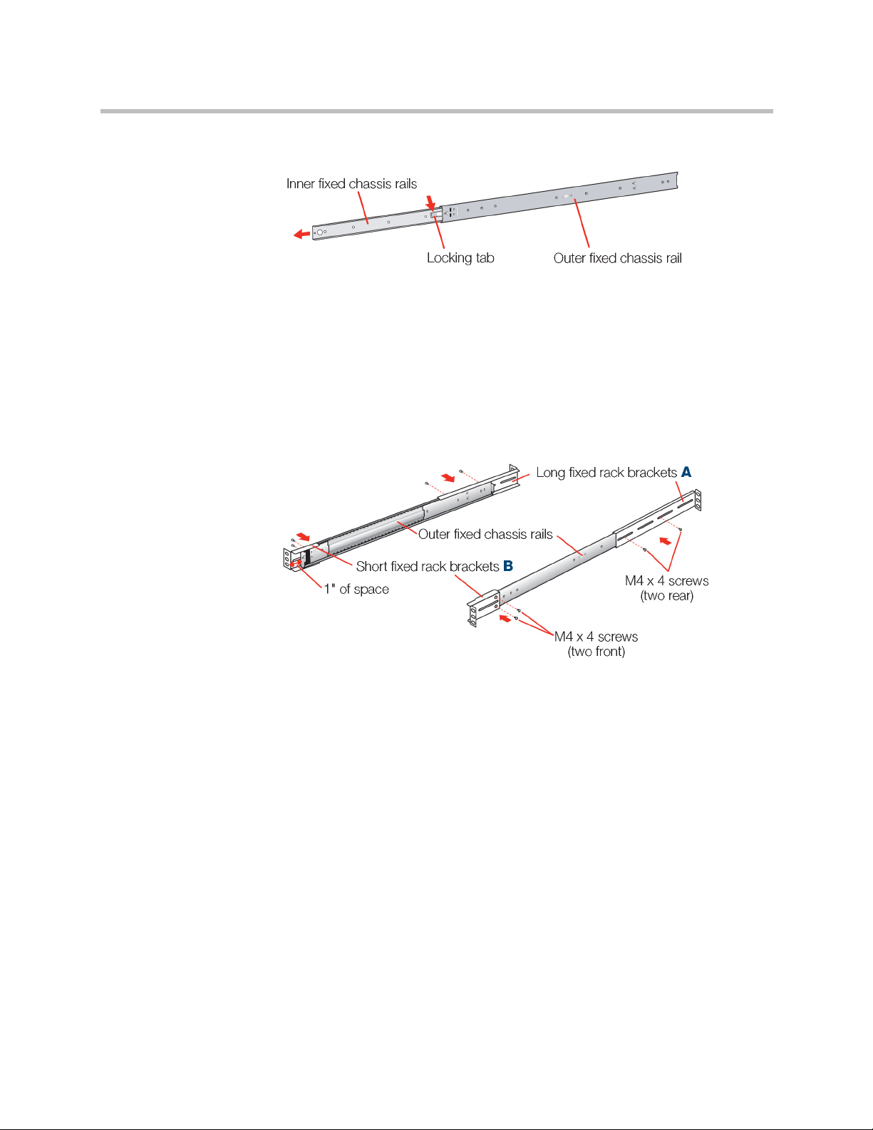
Step 1:
1 Remove the inner fixed chassis rails from the outer fixed chassis rails.
2 Pull each one out as far as possible.
3 Depress the locking tab to pull the inner rail completely out.
4 Put these rails aside for later installation on the appliance.
Step 2:
1 Attach the long (A) and short (B) brackets to the outer fixed chassis rails
as shown, using the shorter ones in the front and the longer ones in the
rear.
2 Leave approximately one inch of space between the front end of the
shorter bracket and the outer fixed chassis rail in the front. The two
vertical holes in the front brackets align with the threaded holes in the
front of the rails.
3 Secure with four M4 x 4 screws, two in the front and two in the rear on
each side.
Polycom, Inc. 9
Page 14
Polycom Video Edge Getting Started Guide Rack Installation
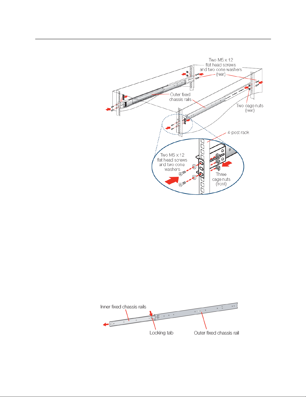
Step 3:
1 Insert a cage nut into each of the square holes in the rack you will be
using as shown (three in the front and two in the rear). They click into
place.
2 Attach the rack /rail assemblies to the 4-post rack using two M5 x 12 flat
head screws and cone washers in the front and back. Make sure the rack /
rail assemblies and screws are aligned in the rack not only in the front
and back, but are level in height on the left and right sides for proper
alignment for appliance installation.
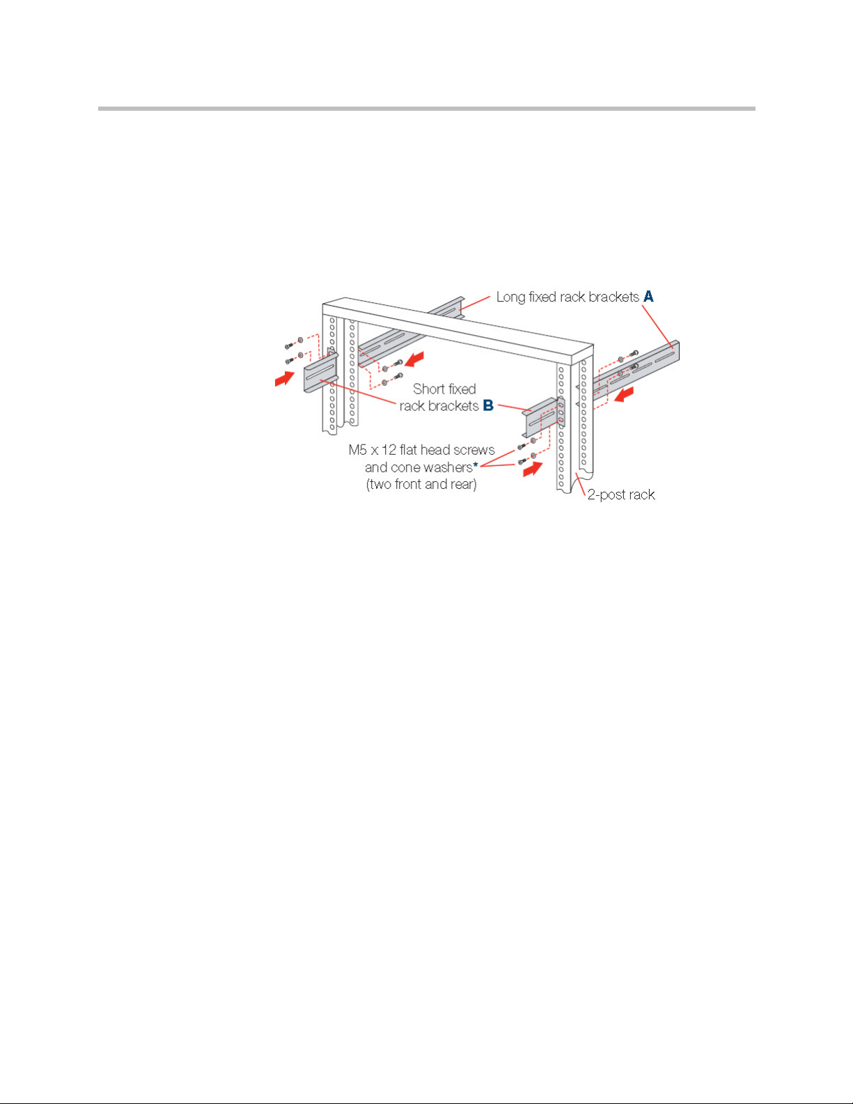
2-Post Rack Installation
Unpack the appliance and locate the mounting hardware.
Step 1:
1 Remove the inner fixed chassis rails from the outer fixed chassis rails.
10 Polycom, Inc.
Page 15
Rack Installation Polycom Video Edge Hardware Setup
2 Pull each one out as far as possible.
3 Depress the locking tab to pull the inner rail completely out.
4 Put these rails aside for later installation on the appliance.
Step 2:
1 Attach the long fixed (A) and the small (B) rack brackets to the 2-post
rack.
2 Mount the short brackets in the front, and the longer brackets in the back
using two M5 x 12 flat head screws and cone washers for each bracket as
shown using the top and bottom holes.
3 Make sure the brackets and screws are aligned in the rack not only in
front and back, but are level in height on the left and right sides for
proper alignment to allow accurate appliance installation.
Polycom, Inc. 11
Page 16
Polycom Video Edge Getting Started Guide Rack Installation
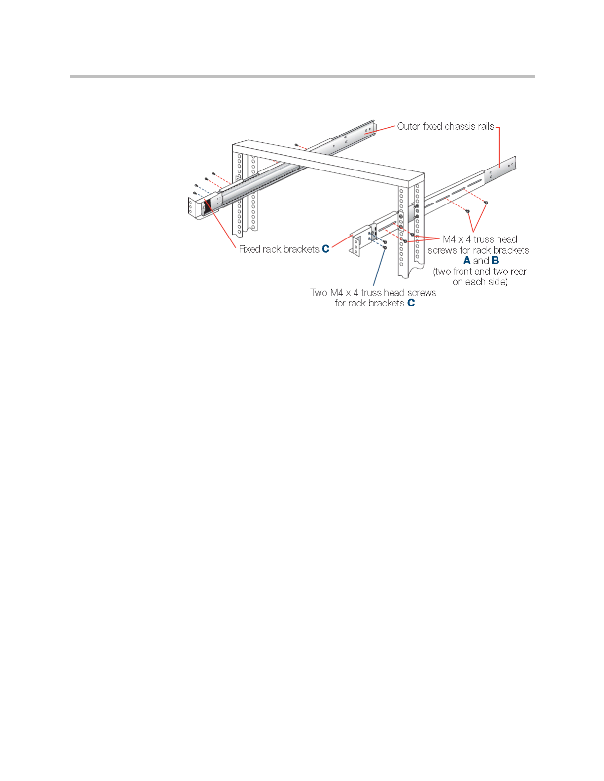
Step 3:
1 Slide each of the outer fixed chassis rails into the left and right fixed
brackets and loosely secure with four M4 x 4 truss head screws on each
side (shown with red dotted lines).
2 Leave enough of the outer fixed rails extended in the front to attach fixed
rack brackets (C) to the rack rails using two M4 x 4 truss head screws on
each side (shown with the blue dotted lines). There should be
approximately one inch of space between brackets (B) and (C) in the
front.
3 Once all screws are in place, tighten each one to securethe outer fixed
chassis rails in place.
12 Polycom, Inc.
Page 17
Rack Installation Polycom Video Edge Hardware Setup
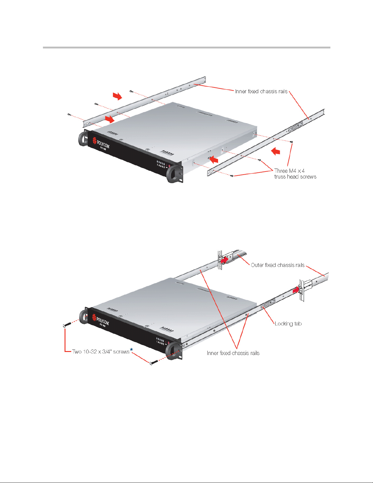
Rail Installation on the Appliance
1 Locate the fixed chassis rails that were put aside.
2 Mount the inner fixed chassis rails to each side of the appliance using
three M4 x 4 truss head screws on the left and right sides as shown.
Installing the Appliance in the Rack
1 Align the inner fixed chassis rails on the appliance with the outer fixed
chassis rails previously installed in the rack.
2 Carefully slide the appliance into these rack rails until you hear the rails
click into place.
3 Push the appliance all the way back into the rack until it stops.
Polycom, Inc. 13
Page 18
Polycom Video Edge Getting Started Guide Rear Panel Connections
4 Secure the unit in the rack by inserting and tightening two 10-32 x 3/4”
screws on each side.
NOTE: Refer to your rack’s mounting hardware for the proper size and type of
screws to secure the appliance in the rack.
NOTE: When removing the appliance from either rack type, you will need to press
down on the locking tab in order to release it from the rack. Carefully slide it out
supporting the unit on both sides at all times.
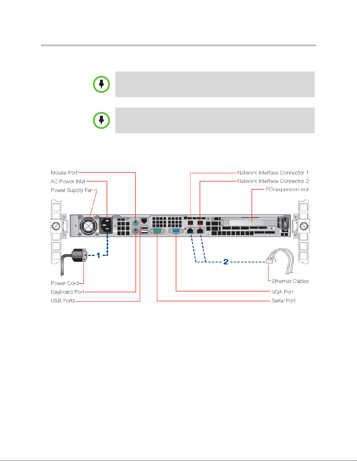
Rear Panel Connections
1 Connect the power cord.
2 Connect the Ethernet cables.
3 Connect any other required cables.
14 Polycom, Inc.
Page 19

Front Panel Operation Polycom Video Edge Hardware Setup
Front Panel Operation
1 Power on the appliance by pressing the Power Button (the last button on
the right on the front of the appliance).
2 The LEDs will begin to blink.
Polycom, Inc. 15
Page 20

Polycom Video Edge Getting Started Guide Front Panel Operation
16 Polycom, Inc.
Page 21

Polycom Video Edge Configuration
This guide explains how to perform initial setup for the Polycom Video Edge
video distribution network. It contains the following sections:
• Video Edge System Configuration in the VMC 1000
• RHQ Configuration
2
Video Edge System Configuration in the VMC 1000
Prior to registering individual Video Edge devices, users must specify a
common system configuration in the VMC. This step must be completed
before any setup on the Video Edge itself can be completed.
Polycom, Inc. 17
Page 22
Video Edge Getting Started Guide Video Edge System Configuration in the VMC 1000
To set the system configuration for all Video Edge devices:
1 Log in to the Polycom VMC 1000 Administrative Portal. Navigate to
System > Video Edge Configuration.
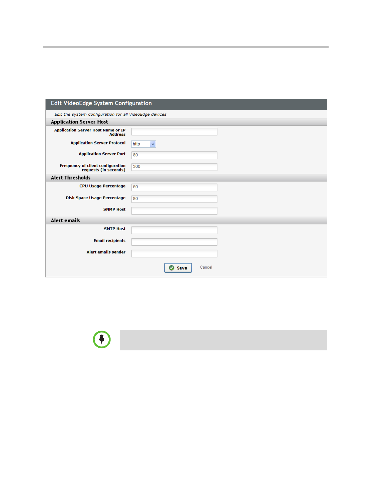
The Edit Video Edge System Configuration page should appear.
2 Specify the Host Name or IP Address.
3 Specify the Protocol. The options are HTTP or HTTPS. Consult the
Polycom VMC 1000 Administrative Guide for information on HTTPS
configuration.
4 Provide the Application Server Port.
NOTE: While configuring HTTP enabled streaming, both origin WMS HTTP PORT
and edge WMS HTTP PORT should match.
5 Provide the Frequency of client configuration requests. This dictates the
space between configuration requests generated in the VMC 1000.
6 Choose alert thresholds for CPU Usage Percentage and Disk Space
Usage Percentage. When these points are reached, an alert will appear in
the Video Edge user interface and will be retransmitted to the VMC 1000
via SNMP.
7 Define the SNMP Host.
18 Polycom, Inc.
Page 23

RHQ Configuration Polycom Video Edge Configuration
8 In the Alert Emails area, define the SMTP Host. Provide a list of
recipients and a default source email address for email alerts.
RHQ Configuration
In order for the Polycom Video Edge monitoring tools to function properly,
the RHQ Portal on the Polycom VMC 1000 server must be configured
correctly. The RHQ Portal is installed by default on the Polycom VMC 1000
appliance.
Server IP Address
The Endpoint Server IP Address value in the RHQ Portal is automatically
determined during the installation process. However, if the IP address for the
Polycom VMC 1000 appliance has changed, this value must be edited by an
administrator.
1 Log into the RHQ Portal.
The RHQ Portal can be accessed through your Internet browser at the
address http://<PolycomVMC1000IP>/qmm/Login.do. The default
administrator/password credentials are rhqadmin/rhqadmin.
NOTE: If the RHQ portal cannot be accessed at the URL given above, please refer
to “Troubleshooting RHQ Configuration” on page 23 below.
2 Open Administration > High Availability > Servers from the RHQ
toolbar.
Polycom, Inc. 19
Page 24

Video Edge Getting Started Guide RHQ Configuration
3 The Manage Servers page will appear. Verify that the “Endpoint
Address” field contains the right VMC 1000 host name or IP address. If
the address is correct, please skip to the subsequent section.
If this address is not correct, it cannot be resolved by the Polycom Video
Edge devices and steps 4-7 must be followed.
4 Click the link that says QMM.
5 The Server Details will appear. Click the grey Edit button.
6 In the screen that appears, change the Address to reflect the new IP.
7 Click Save.
20 Polycom, Inc.
Page 25

RHQ Configuration Polycom Video Edge Configuration
RHQ Shared Key Configuration
In order for the Polycom VMC 1000 Administrative Portal to communicate
with RHQ, the VMC 1000 and RHQ must share a key used for encrypting the
single sign-on token. The following steps outline the process of setting this
key.
To configure a shared RHQ key within the Administrative Portal:
1 Open the Polycom VMC 1000 Administrative Portal.
Navigate to System > Component Configuration.
Polycom, Inc. 21
Page 26

Video Edge Getting Started Guide RHQ Configuration
2 Click Edit beside Device Management.
3 Provide a Device Token Validity Time. The time (in seconds) designated
here accomodates for potential latency in the request between the
requesting service on the Video Edge device and the receiving server.
Polycom recommends a value between 150 and 300 seconds for Device
Token Validity Time to accomodate discrepancies between system clocks.
4 Provide a Server Token Validity Time. The time (in seconds) designated
here accomodates for potential latency in the request between the
requesting service and the receiver, both located on the server running
the Polycom VMC 1000 appliance.
Polycom recommends that the Server Token Validity Time be set to 60.
5 Enter an SSO Password. This is the key used to encrypt the token.
NOTE: Save this value. The SSO Password value must match across the VMC and
RHQ.
6 Click Save.
22 Polycom, Inc.
Page 27

RHQ Configuration Polycom Video Edge Configuration
To configure the shared key in the RHQ Portal:
1 Open the RHQ Portal. Navigate to Administration > System
Configuration > Settings. The Settings page will appear.
2 Under General Configuration Properties, enter the SSO Password you
provided above.
3 Scroll to the bottom of the page and click OK.
Troubleshooting RHQ Configuration
If http://<PolycomVMC1000IP>/qmm/Login.do fails to load, perform the
following troubleshooting steps:
1 Launch IIS Manager. Navigate to the server level.
2 Select Feature Delegation. Make delegation for Modules Read/Write.
Close Delegation.
3 Navigate to Default Web Site > jakarta virtual directory.
4 Double-click on Modules. Select CustomErrorModule and remove it.
If the module is locked it has to be deleted on the Default Web Site level.
The CustomErrorModule module must first be unlocked.
5 Return to the server level and navigate to Feature Delegation. Revert
delegation for Modules to Read Only.
Polycom, Inc. 23
Page 28

Video Edge Getting Started Guide RHQ Configuration
24 Polycom, Inc.
Page 29

Starting the Video Edge
The Polycom Video Edge requires initial configuration via the browser-based
Appliance Manager. This chapter explains how to use the Appliance Manager.
This chapter includes the following sections:
• Preparations
• Requirements
3
Preparations
Requirements
• Locating Serial Numbers
• Connecting Your PC to the PVE 1000 Appliance
• Polycom PVE 1000 Appliance Wizard
• Next Steps
To configure the Polycom PVE 1000 appliance as part of the Polycom video
conferencing solution, you must have the:
• Polycom PVE 1000 appliance.
• PC to initialize and configure the PVE 1000 appliance.
• Crossover cable to connect the PC to the PVE 1000 appliance.
The following are minimum requirements for the PC to configure the PVE
1000 appliance:
Appliance Manager
— Operating Systems: Windows XP, Windows Vista, Windows 7,
Windows Server 2003, Windows Server 2008.
Polycom, Inc. 25
Page 30

Polycom Video Edge Getting Started Guide Connecting Your PC to the PVE 1000 Appliance
—Browsers:
» Internet Explorer: The Polycom PVE 1000 Appliance Manager is
verified to work with Internet Explorer 8.0 and the current release
of Firefox, which at the time of the update of this documentation
is 3.5.5.
Polycom VMC 1000 Administrative Portal
— Operating System: Windows XP, Windows Vista, Windows Server
2003, Windows Server 2008.
—Browsers:
» Internet Explorer: the Polycom PVE 1000 Administrative Portal is
verified to work with Microsoft Internet Explorer 7.0 or 8.0 with
the features JavaScript, Enable Java, and Accept Cookies enabled.
Connecting Your PC to the PVE 1000 Appliance
1 Turn on your PC.
2 On the PC, go to Start > Control Panel > Network Connections.
3 Right click Local Area Connections and select Properties.
4 Scroll down to the Internet Protocol (TCP/IP) option and highlight it.
5 Click Properties.
26 Polycom, Inc.
Page 31

Connecting Your PC to the PVE 1000 Appliance Starting the Video Edge
6 Click the Use the following IP address button.
7 Turn on the PC and configure your PC (LAN) with:
— IP Address: 192.168.254.11
— Mask: 255.255.255.0
— Gateway: 192.168.254.1
Port 10443 should be open on the firewall, or the firewall should be
disabled.
8 Plug the crossover cable into the network connection (LAN 1) for the PVE
1000 appliance.
9 Plug the crossover network cable into the network connection for the PC.
10 Turn on the Polycom PVE 1000 appliance.
11 Launch your Internet browser and navigate to
https://192.168.254.10:10443/qam.
12 The Polycom PVE 1000 Appliance Manager will launch.
Log into the Polycom PVE 1000 Appliance Manager using the following
credentials:
User Name: applianceadmin
Password: D3F@ultP@55w0rD
Polycom, Inc. 27
Page 32

Polycom Video Edge Getting Started Guide Polycom PVE 1000 Appliance Wizard
Polycom PVE 1000 Appliance Wizard
Prior to performing any configuration changes in the Polycom PVE 1000
Appliance Manager, you must perform an initial configuration.
Using the Appliance Wizard
The Polycom PVE 1000 Appliance Manager includes an Appliance Wizard to
assist you in necessary initial configuration.
NOTE: All users must use the Appliance Wizard to perform initial configuration. If
at any point you encounter a configuration step that needs further explication, click
the Help link in the upper left-hand corner.
To use the Appliance Wizard:
1 The Appliance Manager will launch in Appliance Wizard mode. This will
launch the Appliance Wizard.
2 The Welcome Page will appear. Please read and review the contents of
this page before clicking Next.
28 Polycom, Inc.
Page 33
Polycom PVE 1000 Appliance Wizard Starting the Video Edge
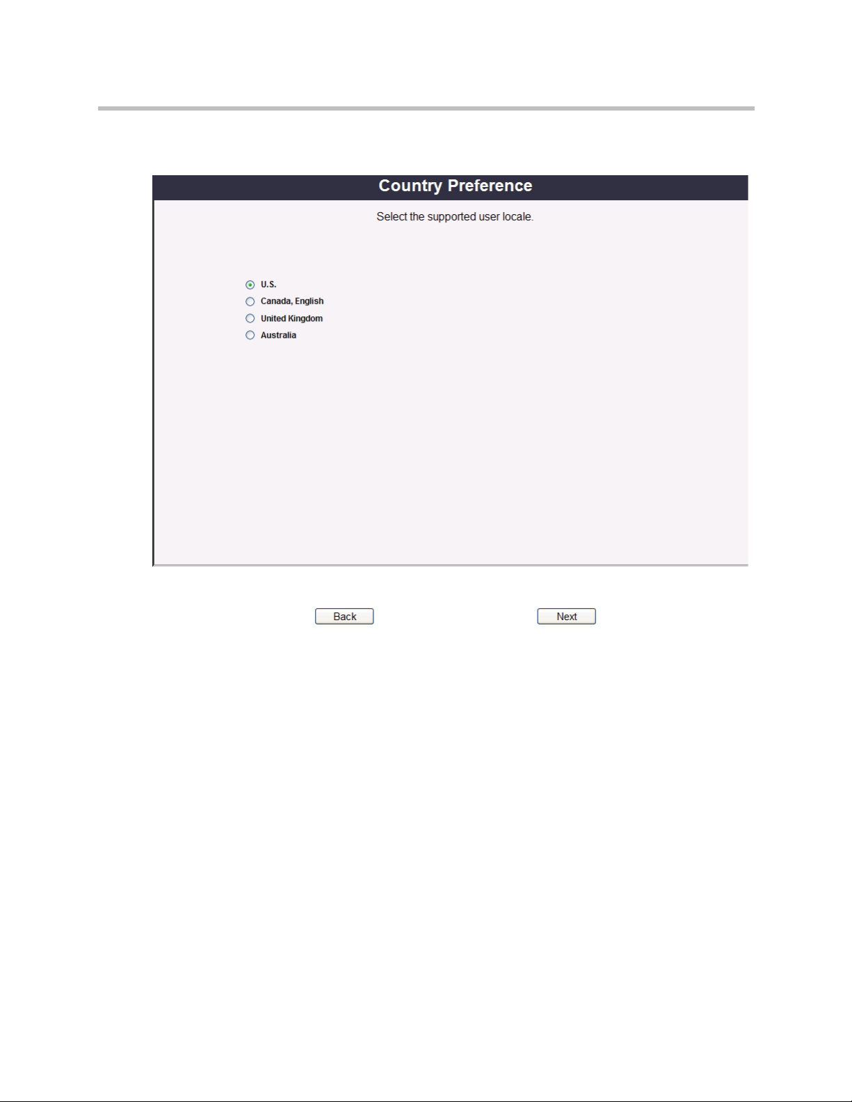
3 The Country Preference dialog will appear. Choose a preference and
click Next.
Polycom, Inc. 29
Page 34

Polycom Video Edge Getting Started Guide Polycom PVE 1000 Appliance Wizard
4 The Windows License dialog will appear. You will prompted to enter
your Windows License Key.
Choose a License Type from the drop-down menu.
The license types include:
—OEM: OEM licensing is the most frequent license case. In this case, the
license key should be on the outside of the appliance. The license key
should already be present. Double-check with the key on the outside
of the appliance and proceed..
NOTE: For most users, the Polycom appliance will use OEM licensing. Proceed to
the next step. If you are unsure of your licensing type, contact your Polycom sales
representative.
— Evaluation: An evaluation license is a temporary permit to use the
appliance. The sole purpose of this license is to bridge the operation of
the appliance while the user is providing a permit license solution,
e.g., a Key Management Server license.
— Key Management Server (KMS): KMS is one of two Microsoft
volume licensing agreements. If you choose KMS, the license key will
be filled by the application. If chosen, you will also need to enter:
30 Polycom, Inc.
Page 35

Polycom PVE 1000 Appliance Wizard Starting the Video Edge
» Server Name: the name of the key management server. If left
blank, Windows Server should attempt to discover the server
within the domain.
» Server Port: the port number of the key management server. If left
blank, Windows Server should attempt to discover the server
within the domain, using the default port number.
— Multiple Access Key (MAK): MAK is the other form of volume
licensing agreement. The dialog is similar to KMS. If chosen, you will
also need to enter:
» Server Name: the name of the multiple access key server. If left
blank, Windows Server should attempt to discover the server
within the domain.
» Server Port: the port number of the multiple access key server. If
left blank, Windows Server should attempt to discover the server
within the domain, using the default port number.
»License Key: the license key you received as part of the MAK
agreement for Windows 2008 Enterprise servers.
NOTE: For both MAK and KMS licensing, an Enterprise license is required for
multicast.
— Retail: a Retail license is a single use license for Windows 2008R2
Enterprise Server obtained through Microsoft. This is an off-the-shelf
license, e.g., one obtained through an online store that contains media
and the license.
— Other : Many of the license keys have identical formats. You may have
received a key; but, you do not know which type of license the key
represents. In such a case, you can try to use the "other" license type to
attempt to register the license. The appliance will try to match the key
to a license type and register the license using Windows 2008
Enterprise server.
When you have selected your Windows License Type and entered your
Windows License Key, click Next. It will take 60 seconds for the
information to be processed.
Polycom, Inc. 31
Page 36

Polycom Video Edge Getting Started Guide Polycom PVE 1000 Appliance Wizard
5 The Appliance License Registration dialog will then appear. Click Next.
You do not need to enter any information in this dialog.
32 Polycom, Inc.
Page 37

Polycom PVE 1000 Appliance Wizard Starting the Video Edge
6 The Security Downgrade dialog will then appear.
This page allows you to downgrade the security constraints for the
Polycom PVE 1000 appliance. If your license agreement permits it, you
may select the Lower Security Level checkbox to downgrade the
appliance to Secure setting. This allows appliance administrators to more
set lower-than-default security requirements.
NOTE: Lower Security Level is a one-time choice. The application of a higher
security level cannot be undone with restoring system defaults.
Please note that appliance licenses that mandate a higher security level will not
allow a security downgrade.
In the Login Greeting field, you may edit the default text and HTML for
the login screen for the Appliance Manager. Once you have completed all
edits, click Next.
Polycom, Inc. 33
Page 38

Polycom Video Edge Getting Started Guide Polycom PVE 1000 Appliance Wizard
7 The User Registration dialog will appear. Enter your information into the
appropriate fields. Click Next when complete.
NOTE: This information is maintained on the appliance. It is not sent over the
network.
34 Polycom, Inc.
Page 39

Polycom PVE 1000 Appliance Wizard Starting the Video Edge
8 The Network Names dialog will appear. Enter the computer name and
the DNS suffix you wish to use for the appliance. Click Next.
Polycom, Inc. 35
Page 40

Polycom Video Edge Getting Started Guide Polycom PVE 1000 Appliance Wizard
9 The Network Configuration dialog will appear. Here you can associate
the Management Application or Appliance Manager with network
interface module independent from that used by the Web Application
(the Video Edge tool itself).
This dialog will also allow you to configure the ports and IP addresses
used by those modules.
a In the Bindings tab, designate which Network Adapter you wish to
use for both the Management Application and the Web Application.
Please note that if you wish to designate independent IP addresses
for the Management and Web Applications, you must select separate
network adapters.
b To configure a network interface, navigate to the eth0 or eth1 tabs,
depending on which adapter you wish to edit.
c Configure the IP address for the network interface:
36 Polycom, Inc.
Page 41

Polycom PVE 1000 Appliance Wizard Starting the Video Edge
» If you have chosen IPv4, you will need to choose whether to use
DHCP, DHCP with manual address, Manual (which will use a
static address, designated in the subsequent fields), or Off (which
will disable the address).
» If you have chosen IPv6, choose either Automatic or Manual
(which will use a static address, designated in the subsequent
fields).
NOTE: Polycom strongly recommends using a static IP address for the network
interface used by the Management Application.
d Click Save and return to the ApplPorts tab.
e If you need to change the ports used by the Web and Management
Applications, you may do so now. Leave the HTTP Port field under
Management Application blank.
NOTE: If you do not designate separate network interfaces for the Web and
Management Applications, they must not use the same ports.
Click Next.
Polycom, Inc. 37
Page 42

Polycom Video Edge Getting Started Guide Polycom PVE 1000 Appliance Wizard
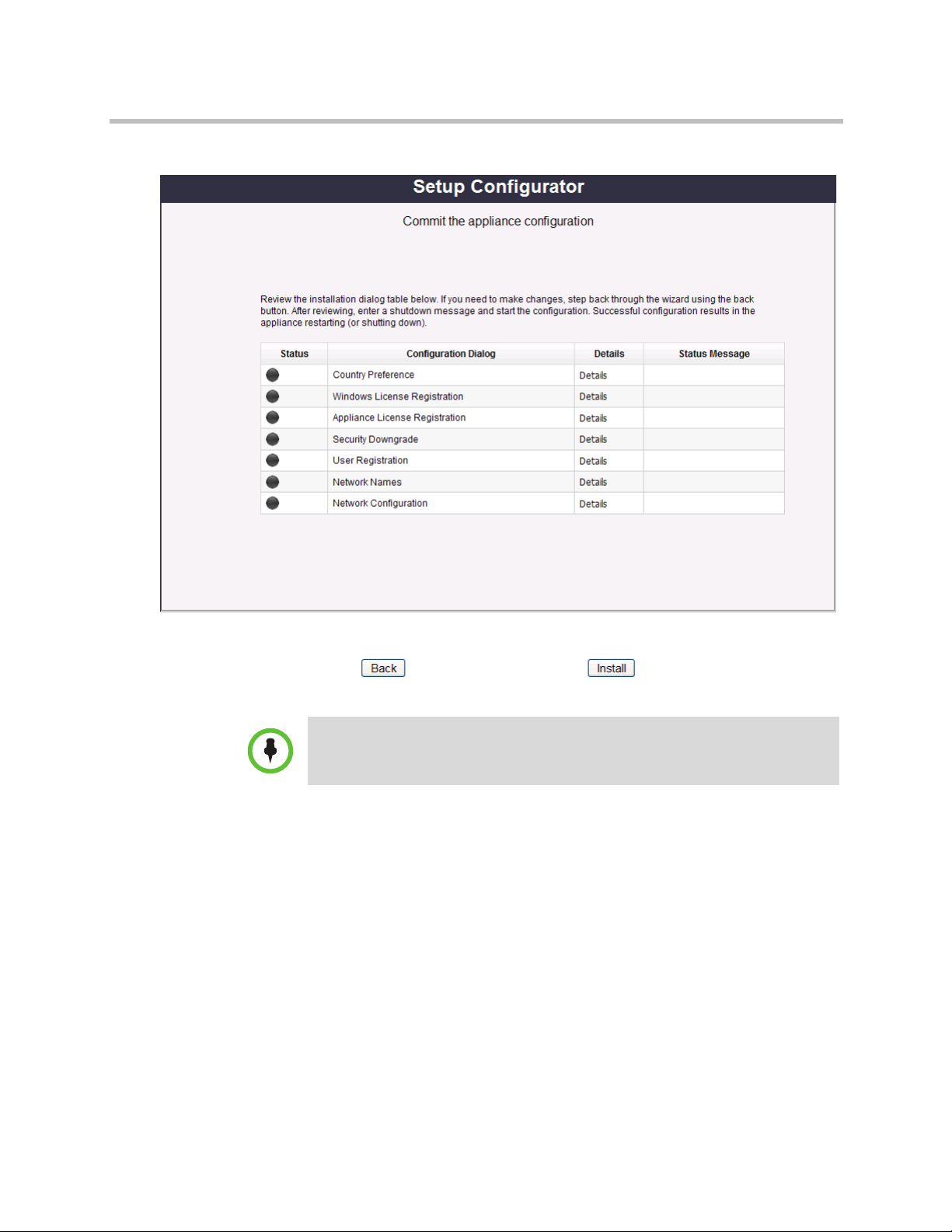
10 A final summary window will appear. Click the Details link beside each
item in the table in order to review your configuration information.
Click Setup Shutdown to complete the configuration.
38 Polycom, Inc.
Page 43

Polycom PVE 1000 Appliance Wizard Starting the Video Edge
11 After installing, you will be prompted to restart the appliance. Choose the
Restart radio button and enter any text in the explanation field.
Polycom, Inc. 39
Page 44
Polycom Video Edge Getting Started Guide Next Steps
12 You will then be returned to the summary screen. Click Install.
The Polycom PVE 1000 Appliance will then restart.
NOTE: You must restart the appliance in order to apply all changes.
Next Steps
After completing the Appliance Wizard and performing a restart, you should
proceed to perform all necessary VMC-side configuration. The steps on
registering a Video Edge device in the VMC follow in “Device Registration”
on page 17.
Performing Further Appliance Configuration
The Polycom PVE 1000 Appliance Manager enables further setup tools via the
Appliance Configurator. The Appliance Configurator can be accessed at the
following URL:
40 Polycom, Inc.
Page 45

Next Steps Starting the Video Edge
https://<ManagementAppIP>:<port>/qam/
where <ManagementAppIP> is the name or IP Address of the Polycom PVE
1000 management application, and <port> is the port assigned to the
management application (usually 10443). Both variables were configured in
the wizard, as detailed above.
The Appliance Configurator is described in “Appendix A: Using the
Appliance Configurator” on page 47.
Polycom, Inc. 41
Page 46

Polycom Video Edge Getting Started Guide Next Steps
42 Polycom, Inc.
Page 47

Device Registration
After initial configuration, Video Edge devices must be registered with the
VMC 1000. This must occur through the VMC 1000 Video Edge Device page.
This chapter includes the following sections:
• Device Registration through the VMC 1000
4
Device Registration through the VMC 1000
Each physical Video Edge device can be registered through the VMC 1000. To
add a Video Edge Device in the VMC 1000 interface:
1 Log in to the VMC 1000 Administrative Portal.
2 Navigate to Delivery > Video Edge Devices. If devices have already
been configured, a list of extant devices should appear.
Polycom, Inc. 43
Page 48

Video Edge Getting Started Guide Device Registration through the VMC 1000
3 Click Add. The Add Device screen should appear.
4 Specify a Device Name.
NOTE: the Device Name field must not include underscores or special characters.
5 Specify a Device Network Address. This is not an IP assignment but
insteadrefers to the existing device IP.
6 Select Active if you want the device to be used immediately upon
configuration.
7 Designate an HTTP protocol. This protocol should be consistent between
the Video Edge device and the Polycom VMC 1000.
8 The fields WMS Multicast Supported and Flash Live Enabled should be
automatically populated with information from the device.
44 Polycom, Inc.
Page 49

Device Registration through the VMC 1000 Device Registration
9 If you wish to associate the device with a specific profile regardless of the
groups with which it is associated, expand Advanced Profile
Configuration. Select Override Group Profile and choose a specific
profile from the drop-down menu.
Please consult the Polycom PVE 1000 Administrator Guide for more
information on Profiles.
NOTE: the Override Group Profile option is not recommended for most users.
Polycom, Inc. 45
Page 50

Video Edge Getting Started Guide Device Registration through the VMC 1000
46 Polycom, Inc.
Page 51

Appendix A: Using the Appliance Configurator
The PVE 1000 requires initial configuration via the browser-based Appliance
Manager. This chapter explains how to use the Configurator section of the
Appliance Manager.
A
This chapter includes the following sections:
• About the Appliance Configurator
• System
• Network
• User Management
• Operations
About the Appliance Configurator
After running the Appliance Wizard and restarting the Polycom PVE 1000
appliance, further configuration can be performed via the Appliance
Configurator. The Appliance Configurator will launch by default upon
accessing the Appliance Manager.
The Appliance Configurator allows changes to the configurations made in
each of the Appliance Wizard dialogs detailed above, with the exception of the
permanent Security Downgrade dialog.
The Appliance Configurator also allows for security profile management, user
management, and network configuration.
Polycom, Inc. 47
Page 52

Polycom VMC 1000 Getting Started Guide System
System
The System node provides a set of tools that allow users to perform basic
system configuration. The following dialogs can be accessed via the System
node:
• About
• Country Preference
• Windows License
• Appliance License
• Registration
• Date and Time
• Security Profile
• Restore Defaults
• System Profile
Please note that the Country Preference, Windows License, Appliance License,
and Registration dialogs duplicate dialogs accessible via the Appliance
Wizard. For information on these dialogs, please consult the previous chapter.
About
The About dialog provides a summary of the Management Application
information, Windows and Polycom License Keys and features, and any
important messages related to system and license settings.
48 Polycom, Inc.
Page 53

System Appendix A: Using the Appliance Configurator
Date and Time
The Date, Time, and Timezone dialog allows you to set the appliance date,
time, and time zone:
1 Indicate the month, year, and date in the Date region.
2 Indicate whether you want to use a Network Time Provider or System
Clock. An NTP Server will automatically maintain the date and time for
the timezone you select; if you choose System Clock, the date and time
will be maintained locally on the Polycom PVE 1000 appliance.
3 If you choose Network Time Provider, you will be prompted to select an
Network Time Protocol Server from the drop-down list.
4 Click Edit to launch a dialog to Add, Remove, or Select All NTP servers
from the pre-configured list. Once complete with this dialog, click Done.
5 If you choose System Clock, you will be prompted to enter the correct
appliance time
6 Indicate a Timezone from the drop-down menu.
7 When all configuration has been completed, click Next.
Polycom, Inc. 49
Page 54

Polycom VMC 1000 Getting Started Guide System
Security Profile
Although the security level for the Polycom PVE 1000 appliance cannot be
changed after running the initial configuration wizard, security setting
changes can be made via the Appliance Configurator.
1 Navigate to System > Security Profile.
NOTE: Do not click System > Security Profile until after you have run the
Appliance Wizard and restarted the appliance.
2 Set the following values under Account Policy:
— Inactive Session Timeout: the length of time before a session is
logged off due to no user activity.
— Inactive Account Login Timeout: the length of time before the user
account is locked due to no login activity.
— Locked Account Timeout: the length of time an account may be
temporarily locked due to invalid login attempts.
— Password Change Notification Interval: the start of the period in
which the appliance will indicate the pending need for a password
change during login.
— Password Maximum Change Interval: the maximum duration of
time between user password changes.
— Password Minimum Change Interval: the minimum duration of time
between user password changes.
— Maximum Failed Login Attempts: the number of consecutive invalid
passwords before the account is temporarily locked.
— Consecutive Chars in Changed Password: the minimum number of
consecutive changed password characters at any given offset in a
password. With a setting of 4, "ABpass1234" could not be changed to
"CDpass7890," because "pass" occurs at the same offset for the
minimum length in both passwords. On the other hand, changing the
password to "Apass12B34" would be acceptable.
— Password Recycle: the number of password changes before a
password can be reused.
3 Set the following values under Password Policy:
— Minimum Length: the minimum number of characters in a password.
The minimum number of characters in a very secure configuration is
14. In a secure configuration the minimum number of characters is 6.
NOTE: The sum of the uppercase, lowercase, and numeric minimum character
lengths dictated in the fields below cannot exceed the highest possible value in the
minimum-length drop-down.
50 Polycom, Inc.
Page 55

System Appendix A: Using the Appliance Configurator
— Minimum Upper Character Length: the minimum number of upper
case characters.
— Minimum Lower Character Length: the minimum number of lower
case characters.
— Minimum Numeric Character Length: the minimum number of
numeric characters.
— Minimum Number of Characters: the minimum number of
alphanumeric characters.
— Minimum Special Character Length: the minimum number of special
characters.
— Special Character Set: the set of special characters. This set may not be
changed.
4 To disable a given security criterion, select the Disable checkbox if
available.
Please note that no criteria can be disabled in Super Secure configurations.
5 Click Save.
Polycom, Inc. 51
Page 56

Polycom VMC 1000 Getting Started Guide System
Restore Defaults
The Restore Defaults menu allows you to return the appliance to its factory
defaults.
To r es tor e de fau lt s:
1 Select the Restore factory defaults checkbox.
2 Click Save.
3 Click through the confirmation screens that appear.
4 The appliance should restart. You will then need to follow the initial
configuration steps detailed in the previous chapter, starting with
Connecting Your PC to the PVE 1000 Appliance.
System Profile
The System Profile details the status of the Polycom PVE 1000 appliance
system, disks, and network interfaces. Click Refresh to update the screen.
52 Polycom, Inc.
Page 57

Network Appendix A: Using the Appliance Configurator
Network
The following dialogs can be accessed via the Network node:
• Domain Configuration
• Remote Desktop Access
• Network Configuration
• Network Names
• Certificates
• Certificate Authorities
Please note that the Network Configuration and Network Names dialogs
duplicate dialogs accessible via the Appliance Wizard. For information on
these dialogs, please consult the previous chapter.
Domain Configuration
The Domain Configuration page is used to join or leave a Windows Server
Active Directory domain.
Polycom, Inc. 53
Page 58

Polycom VMC 1000 Getting Started Guide Network
To join or leave a domain:
1 Navigate to Network > Domain Configuration.
2 Enter the Domain Name for the domain you wish to enter or leave.
3 Enter the domain administrator user credentials in the Domain User and
Domain Password fields.
4 Choose the Join radio button to join the domain configured above. If you
wish to leave a domain, select the Leave radio button.
5 Click Save.
Remote Desktop Access
This dialog allows you to enable or disable RDP access to the Polycom PVE
1000 appliance. Select allow or block from the drop-down menu and click
Update.
Appliances on Super Secure setting cannot enabled RDP access.
Certificates
The Appliance Manager allows administrators to obtain and review
certificates. Certificates are used to provide encrypted web communication
over HTTPS.
54 Polycom, Inc.
Page 59

Network Appendix A: Using the Appliance Configurator
You will need two certificates: one for the Management Application and one
for the Web Application (if using HTTPS). The interface in each respective tab
is identical. Both will follow the guidelines designated below.
However, you can choose whether to use a certificate generated by a certificate
authority (CA) or a self-signed certificate. The self-signed certificate is
appropriate for internal communications, but will not provide sufficient
encryption for external access. The workflow for each will vary.
To add a self-signed certificate:
1 Open either the Web Application or Management Application tabs.
Polycom, Inc. 55
Page 60

Polycom VMC 1000 Getting Started Guide Network
2 Navigate to Gen Self-Signed Cert.
3 Enter a Common Name, Organizational Unit, Organization, City, State
(if applicable) and Country.
4 Specify a Cryptography Provider from the drop-down menu. The DSA
and RSA algorithms vary slightly in the strength of the encryption and
the time involved in authentication.
5 Click Generate. To review the generated certificate, navigate to the View
tab.
To request and add a certificate:
1 Open either the Web Application or Management Application tabs.
56 Polycom, Inc.
Page 61

Network Appendix A: Using the Appliance Configurator
2 Navigate to Gen Cert Request.
3 Enter a Common Name. The Common Name should comply with the
requirements of your Certificate Authority.
4 Enter your Organizational Unit, Organization, City, State if applicable,
and Country.
5 Specify a Cryptography Provider from the drop-down menu. The DSA
and RSA algorithms vary slightly in the strength of the encryption and
the time involved in authentication.
6 Click Validate. To review the generated certificate, navigate to the View
tab.
7 After the Certificate Authority has validated your certificate request,
navigate to the Import Cert Request tab. Click Import Certificate
Request.
Certificate Authorities
The Certificate Authorities tab allows you to viewand manage appliance
certificates and review Certificate Authorities.
Select an Action from the drop-down menu:
• List the Certificates to obtain a list of the certificates in the store.
• Get a Certificate to view the contents of a specific certificate, chosen from
the Alias drop-down menu.
Polycom, Inc. 57
Page 62

Polycom VMC 1000 Getting Started Guide User Management
User Management
The Appliance Configurator allows users to change and manage permissions
for the Appliance Manager. Please note that the users configured and edited
here are not Polycom PVE 1000 users.
The User Management section contains the following sections:
• Change My Password
• Reset Password
• Add User
• Manage Users
Change My Password
After running the Appliance Wizard and restarting the Polycom PVE 1000
appliance, the Administrator password should be changed from the default.
To change your password:
1 Navigate to User Management > Change My Password.
2 Enter a new password in the Password and Verify Password fields. The
proposed password must meet the account and password policy
requirements set above.
3 Click Save.
Reset Password
To reset a user’s password:
1 Navigate to User Management > Reset Password.
2 Select a user from the drop-down menu.
3 Click Save.
A temporary password will be displayed. Convey this password to the .
After the user first logs in, they should change their password from this
default.
4 Click Cancel to leave the dialog. Do not click Save again.
58 Polycom, Inc.
Page 63

Operations Appendix A: Using the Appliance Configurator
Add User
To add a user:
1 To add a user, navigate to User Management > Add User.
2 Enter a unique User Name.
3 Choose a Role from the drop-down menu.
4 Click Save.
5 A temporary password will be displayed. Save this password in a safe
location. After the user first logs in, they should change their password
from this default.
Manage Users
To m ana ge use rs:
Operations
1 To manage users that have already been added, navigate to User
Management > Manage Users.
2 The Manage Users dialog will appear. The dialog is organized by role.
Click a tab to view the users assigned to that role.
3 To remove a user, click the Delete button. A confirmation dialog will
appear; click Delete again to remove the user.
4 To unlock a user, click the Unlock button.
5 If necessary, click Refresh to update the dialog.
A suite of network utilities can be configured and used via the Polycom PVE
1000 Appliance Manager. The following dialogs can be accessed via the
Operations node:
• Network Shares
• Backup
• Restore
• Logs
• Netstat
• Ping
• Trace Route
Polycom, Inc. 59
Page 64

Polycom VMC 1000 Getting Started Guide Operations
• Route
• IP Config
• Processes
• Upgrade
• Shut Down
Network Shares
Network shares are used for several operations in the Polycom PVE 1000.
Backup uses shares to define the targets for system and content backups.
Restore needs the shares to restore from backups. Upgrade uses shares for the
source and repository stores. The Appliance Configurator allows
administrators to review, edit, and add network shares.
Shared resources must be configured before backup and restore volumes can
be established.
NOTE: Create separate shares for the Content and System backups. The same
network share cannot be used for both system and content images.
To change the network shares configuration:
1 Navigate to Operations > Network Shares. The Network Shares
Configuration Dialog will appear. The dialog will display the status,
share name, address, domain name, and associated user name for all
shared resources.
2 To add a resource, click Add. You will be prompted to supply the
following values:
a Share Name: the share's descriptive name.
b Network Resource Address: the share’s pathway.
c User Domain Name: the domain part of the user credentials.
d User Name: the user name part of the user credentials.
e User Password: the password portion of the user credentials.
When all values have been entered, click Add.
3 To mount the resource, click the Mount button beside its name.
4 To change an existing shared resource, click the Edit button beside the
name. The Edit Network Share dialog will appear.
You will be prompted to supply the user credentials outlined above. Click
Save when complete.
5 To remove a shared resource, click Delete.
60 Polycom, Inc.
Page 65

Operations Appendix A: Using the Appliance Configurator
6 When all changes have been made, click Refresh.
Backup
After configuring network shared resources in the Network Shares region,
administrators can designate backup volumes.
NOTE: The status of a backup in process is not indicated within the Appliance
Manager. To confirm that a backup is complete, consult the backup destination to
view the status of the associated files.
To designate backup volumes:
1 Navigate to Operations > Backup. The backup dialog is divided into two
sections: system and content. Each section has an
administrator-configurable volume and backup schedule. The following
steps apply equally to both sections.
2 Designate a Volume from the drop-down list.
3 Select the Now box if you wish to perform an immediate backup.
4 To establish a schedule, choose a Frequency with which to perform
backups. The frequencies operate as follows:
— Never: Never execute a backup.
—Hourly: Execute a backup each hour at the given minute offset.
—Daily: Execute a backup once a day at the given hour and minute.
—Weekly: Execute a backup once a week on the given day, hour, and
minute.
—Monthly: Execute a backup once a month on the first occurence of the
given day, hour, and minute.
—Once: Execute a backup once on the first occurence of given day, hour,
and minute.
5 Depending on the frequency determined above, designate a Day of the
Week, Hour, and Minute.
6 Click Save.
7 The appliance will reboot upon completion.
Polycom, Inc. 61
Page 66

Polycom VMC 1000 Getting Started Guide Operations
Restore
To perform a restore:
1 Choose a Network Share from the drop-down menu.
2 Designate a date and time to perform the restore.
3 Choose whether to perform a System Images or Content Images backup
restore.
4 Click Restore to start the restore.
5 To review the restore progress, click Current Restore.
6 Restart the appliance using the process outlined above.
7 The appliance will reboot upon completion.
62 Polycom, Inc.
Page 67

Operations Appendix A: Using the Appliance Configurator
Logs
The Polycom PVE 1000 appliance allows you to view a variety of logs. To view
these logs:
1 Navigate to Operations > Logs.
2 In the Categories drop-down menu, choose either System, Audit,
Application, or Management Application.
3 Under Log File Names, choose the log you wish to view.
4 Click View/Refresh.
Netstat
Netstat, accessible at Operations > Netstat, displays the contents of selected
network structures. The comprehensive network statistics and multicast
information options tend to complete quickly. The others are long running
commands.
• Display routing table information shows the current routing table
information.
• Display comprehensive network statistic shows in-depth statistics by
protocol.
• Display multicast information displays multicast information.
Polycom, Inc. 63
Page 68

Polycom VMC 1000 Getting Started Guide Operations
• Display the state of all current socket connections returns the current
state of each socket connection. This command may take several minutes
to complete.
Ping
The ping utility, accessible at Operations > Ping, uses the ECHO_REQUEST
datagram to obtain an ICMP ECHO_RESPONSE from a host or gateway.
• IP Address is the host IP address or name.
•Count is the number of requests to send before returning.
Trace Route
Navigate to Operations > Trace Route to trace the route packets take to a
given host. A traceroute may run for a very long time. A time limit is included
to control the number of minutes you will wait for the command to return.
• IP Address is the host IP address or name.
•Time is the number of minutes to allow the command to execute before
terminating the command and returning the results to that point.
Route
Route is used to manually manipulate the routing tables. This is not normally
needed. The most frequent use is to display the current routing tables.
Manually changing (or flushing) the routing tables may terminate appliance
connections. For more detailed information, please consult Polycom Support.
IP Config
To access the IP Config Viewer, navigate to Operations > IP Config. Click Run
to view the current internet protocol configuration.
Processes
Navigate to Operations > Processes to access the Processes Viewer. This
dialog can be used to obtain a list of the current processes based upon one of
the selected filter criteria:
• Display all processes to obtain a list of all processes.
• Display running processes to obtain a list of all processes in the running
state.
• Display processes that are not running to obtain a list of all processes not
in the running state.
64 Polycom, Inc.
Page 69

Operations Appendix A: Using the Appliance Configurator
• Display Processes that are not responding to obtain a list of all processes
not responding to requests.
After selecting a filter criterion, click Run.
Upgrade
To upgrade the Polycom PVE 1000, users must install an upgrade package.
The installation process uses source and repository locations. Both the source
and repository must be network shares. The source is the location where
packages initially reside, after having been downloaded from elsewhere. The
repository is the staging area where selected packages are held for installation.
The process of applying a package installation is as follows:
1 Navigate to the Network Shares tab. Select a Source Network Share
from the drop-down menu.
Polycom, Inc. 65
Page 70

Polycom VMC 1000 Getting Started Guide Operations
2 Navigate to the Sources tab. Click Download to transfer a package to the
repository.
3 Navigate to the Repository tab. Click Install next to the package you
wish to install.
4 To review installed packages, navigate to the Installed tab.
To review the system fixes installed on the appliance, navigate to the
Hotfixes tab.
Shut Down
The Shut Down dialog allows you to restart or shut down the appliance.
66 Polycom, Inc.
Page 71

Regulatory Notices
Regulatory Notices
USA Regulatory Notices
Part 15 FCC Rules
This device is compliant with Part 15 of the FCC Rules. Operation is subject to the following two conditions:
1 This device may not cause harmful interference, and
2 This device must accept any interferences received, including interference that may cause undesired operation.
Class A Digital Device or Peripheral
NOTE: This equipment has been tested and found to comply with the limits for a Class A digital device, pursuant to
part 15 of the FCC Rules. These limits are designed to provide reasonable protection against harmful interference
when the equipment is operated in a commercial environment. This equipment generates, uses, and can radiate
radio frequency energy and, if not installed and used in accordance with the instruction manual, may cause harmful
interference to radio communications. Operation of this equipment in a residential area is likely to cause harmful
interference in which case the user will be required to correct the interference at his own expense.
In accordance with part 15 of the FCC rules, the user is cautioned that any changes or modifications not expressly
approved by Polycom Inc. could void the user's authority to operate the equipment.
We recommend that you install an AC surge arrestor in the AC outlet to which this device is connected. This action
will help to avoid damage to the equipment caused by local lightning strikes and other electrical surges.
B
Czech Republic Regulatory Notices
Polycom, Inc. 67
Page 72

Polycom Video Edge Getting Started Guide
Regulatory Notices
Canadian Regulatory Notices
Class A Digital Device
This Class [A] digital apparatus complies with Canadian ICES-003.
Cet appareil numérique de la classe [A] est conforme à la norme NMB-003 du Canada.
EEA Regulatory Notices
This Polycom Video Edge has been marked with the CE mark. This mark indicates compliance with EEC Directives
2006/95/EC and 2004/108/EC. A full copy of the Declaration of Conformity can be obtained from Polycom Ltd, 270
Bath Road, Slough, Berkshire, SL1 4DX, UK.
Japanese Regulatory Notices
Worldwide Regulatory Notices
Warning
This is a Class A product. In a domestic environment, this product may cause radio interference in which case the
user may be required to take adequate measures.
Plugs Acts as Disconnect Device
The socket outlet to which this apparatus is connected must be installed near the equipment and must always be
readily accessible.
La prise électrique à laquelle l’appareil est branché doit être installée près de l’équipement et doit toujours être
facilement accessible.
68 Polycom, Inc.
 Loading...