

Page 1

MGC-50/MGC-100
Hardware & Inst allation
Manual
Version 9.0
Page 2

Copyright © 2007 Polycom, Inc.
All Rights Res erved
Catalog No. DOC2193A
Vers ion 9.0
Proprietary and Confidential
The information contained herein is the sole intellectual property of Polycom, Inc. No distribution, reproduction or unauthorized
use of these materials is permitted without the expressed written consent of Polycom, Inc. Information contained herein is subject
to change without notice and does not represent a commitment of any type on the part of Polycom, Inc. Polycom and Accord are
registered trademarks of Polycom , In c.
Notice
While reasonable effort was made to ensure that the information in this document was complete and accurate at the time of
printing, Polycom, Inc. can not assum e responsibility for any errors. Changes an d/or corrections to the information contained in
this document may be inc orporated into future issues.
Page 3

Regulatory Notices
United States Federal Communication
Commission (FCC)
Part 15: Class A Statement. This equipment has
been tested and found to comply with the limits for a
Class A digital device, pursuant to Part 15 of the FCC
Rules. T est limits are designed to provide reasonable
protection against harmful interference when the
equipment is operated in a commercial environment.
This equipment generates, uses, and can radiate
radio-frequency energy and, if not installed and used
in accordance with the instruction manuals, may
cause harmful interference to radio communications.
Operation of this equipment in a residential area is
likely to cause harmful interference, in which case the
user will be required to correct the interference at his
or her own expense.
Part 68: Network Registration Number. This
equipment is registered with the FCC in accordance
with Part 68 of the FCC Rules. This equipment is
identified by the FCC registration number.
If requested, the FCC registration Number and REN
must be provided to the telephone company.
Any repairs to this equipment must be carried out by
Polycom Inc., or our designated agent. This
stipulation is required by the FCC and applies during
and after the warranty period.
United St a tes Safety Constructi on Details
• Unit is intended for RESTRICTED ACCESS
LOCATION.
• Unit is to be installed in accordance with the
National Electrical Code.
• The branch circuit overcurrent protection shall
be rated 20 A for the AC system.
• This equipment has a maximum operating
ambient of 40°C, the ambient temperature in
the rack shall not exceed this temperature.
For DC system only:
• Use 10 AWG copper conductors.
• Connect to a reliably grounded 48 V DC SELV
source.
Caution: This equipment has a connection
between the earthed conductor of the DC
supply circuit and the earthing conductor. See
Installation Instructions.
• This equipment shall be located in the same
immediate area (such as, adjacent cabinets or
any other equipment that has a connection
between the grounded conductor of the same
DC supply circuit and the grounding conductor,
and also the grounding connection of the DC
system.) The DC system shall not be grounded
elsewhere.
EC Mark R&TTE Directive
Polycom Inc., declares that the MGC-50 and
MGC-100 with NET-2/4/8 card is in conformity with
the following relevant harmonized standards:
EN 60950: 1992 Including Amendments 1,2,3 & 4
EN 55022: 1994
EN 50082: 1997
Following the provisions of the Council Directive
1999/EC on radio and telecommunication terminal
equipment and the recognition of its conformity.
Canadian Department of Communications
This Class [A] digital apparatus complies with
Canadian ICES-003.
Notice: The Industry Canada label identifies certified
equipment. This certification means that the
equipment meets telecommunication network
protective, operational and safety requirements as
prescribed in the appropriate Terminal Equipment
Technical Requirements document(s). The
Department does not guarantee the equipment will
operate to the user's satisfaction.
Before installing this equipment, users should ensure
that it is permissible to be connected to the facilities
of the local telecommunications company. The
equipment must also be installed using an acceptable
method of connection. The customer should be
aware that compliance with the above conditions may
not prevent degradation of service in some situations.
Repairs to certified equipment malfunctions, may give
the telecommunications company causes to request
the user to disconnect the equipment.
Users should ensure for their own protection that the
Page 4
Regulatory Notices
electrical ground connections of the power utility,
telephone lines and internal metallic water pipe
system, if present, are connected together. This
precaution may be particularly important in rural
areas.
Caution: Users should not attempt to make such
connections themselves, but should contact the
appropriate electric inspection authority, or
electrician, as appropriate.
Taiwan
Russian Communication Certificate
The MGC-100 and MGC-50 comply with the Russian
Ministry of Communication requirements stated in
certificate OC/1-MM-15.
Page 5

Table of Contents
Before You Begin . . . . . . . . . . . . . . . . . . . . . . . . . . . . . . . . . . 1-1
MGC Unit Main Features . . . . . . . . . . . . . . . . . . . . . . . . . . . . . . . . . . 1-3
MGC-50/MGC-100 Specifications . . . . . . . . . . . . . . . . . . . . . . . . . . . 1-4
Scope of Manual . . . . . . . . . . . . . . . . . . . . . . . . . . . . . . . . . . . . . . . . . 1-8
Conventions . . . . . . . . . . . . . . . . . . . . . . . . . . . . . . . . . . . . . . . . . . . . 1-9
List of Abbreviations . . . . . . . . . . . . . . . . . . . . . . . . . . . . . . . . . 1-10
Installation and Configuration Workflow . . . . . . . . . . . . . . . . . . . . . 1-11
Hardware Installation . . . . . . . . . . . . . . . . . . . . . . . . . . . . . . . 2-1
MGC-100 Hardware Installation . . . . . . . . . . . . . . . . . . . . . . . . . . . . 2-2
Unpacking and Positioning the MGC-100 . . . . . . . . . . . . . . . . . 2-2
Mounting the MGC-100 on a 23” Rack . . . . . . . . . . . . . . . . . . . 2-4
Mounting the MGC-100 on a 19” Rack . . . . . . . . . . . . . . . . . . . 2-6
NEBS Standard . . . . . . . . . . . . . . . . . . . . . . . . . . . . . . . . . . . . . . 2-8
Connecting and Setting Up the MGC-100 . . . . . . . . . . . . . . . . . 2-9
MGC-100 Dongle . . . . . . . . . . . . . . . . . . . . . . . . . . . . . . . . 2-10
Connecting to the power source . . . . . . . . . . . . . . . . . . . . . 2-10
Connecting the MGC-100 to the LAN Network . . . . . . . . . 2-12
Connecting the MGC-100 to the Operator
Workstation (PC) Directly via RS-232 (Optional) . . . . . . . 2-12
Connecting the MGC-100 to the Network . . . . . . . . . . . . . 2-13
MPI-4/8 Hardware Installation for the MGC-100 . . . . . . . . . . . 2-16
To install the MPI-4/8 Network Interface Module: . . . . . . 2-17
To install the MPI Box on Top of the MCU: . . . . . . . . . . . 2-17
MGC-50 Hardware Installation . . . . . . . . . . . . . . . . . . . . . . . . . . . . 2-21
Unpacking and Positioning the MGC-50 . . . . . . . . . . . . . . . . . 2-21
Mounting the MGC-50 on a Rack . . . . . . . . . . . . . . . . . . . . . . . 2-23
Connecting and Setting Up the MGC-50 . . . . . . . . . . . . . . . . . 2-26
MGC-50 Dongle . . . . . . . . . . . . . . . . . . . . . . . . . . . . . . . . . 2-26
Connecting to the Power Source . . . . . . . . . . . . . . . . . . . . . 2-27
Connecting the MGC-50 to the LAN Network . . . . . . . . . . 2-28
MGC Hardware and Installa t ion Guide
i
Page 6

Table of Contents
Connecting the MGC-50 to the Operator
Workstation (PC) Directly via RS-232 (Optional) . . . . . . . 2-28
Connecting the MGC-50 to the Network . . . . . . . . . . . . . . 2-28
Connecting the MGC-50 to the ATM Network . . . . . . . . . 2-30
Connecting the MGC-50 to the IP Network . . . . . . . . . . . . 2-31
MPI-8 Hardware Installation for the MGC-50 . . . . . . . . . . . . . 2-32
First Entry IP Configuration . . . . . . . . . . . . . . . . . . . . . . . . . . . . . . . 2-35
IP Configuration Change on XPEK and pSOS OS . . . . . . . . . 2-35
Using a DOS Diskette with the Updated
LAN.CFG File . . . . . . . . . . . . . . . . . . . . . . . . . . . . . . . . . . 2-39
Clocking . . . . . . . . . . . . . . . . . . . . . . . . . . . . . . . . . . . . . . . . . . . . . . 2-41
System Architecture . . . . . . . . . . . . . . . . . . . . . . . . . . . . . . . . 3-1
Information Flow . . . . . . . . . . . . . . . . . . . . . . . . . . . . . . . . . . . . . . . . 3-7
MGC Manager Interface . . . . . . . . . . . . . . . . . . . . . . . . . . . . . . . . . . 3-9
Power Supply Flow . . . . . . . . . . . . . . . . . . . . . . . . . . . . . . . . . . . . . . 3-9
Hardware Description . . . . . . . . . . . . . . . . . . . . . . . . . . . . . . . 4-1
MGC-100 Components Location . . . . . . . . . . . . . . . . . . . . . . . . . . . . 4-2
MGC-50 Components Location . . . . . . . . . . . . . . . . . . . . . . . . . . . . . 4-7
Main Control Module . . . . . . . . . . . . . . . . . . . . . . . . . . . . . . . . . . . . 4-10
MGC-50/100 Control Unit with Removable Hard Drive . . . . . 4-12
Removing the Control Unit from the MCU . . . . . . . . . . . . 4-12
Control Unit Installation . . . . . . . . . . . . . . . . . . . . . . . . . . . 4-13
IP Configuration Change . . . . . . . . . . . . . . . . . . . . . . . . . . 4-14
Hard Drive Operation . . . . . . . . . . . . . . . . . . . . . . . . . . . . . 4-14
Inserting the Hard Drive . . . . . . . . . . . . . . . . . . . . . . . . . . . 4-15
Removing the Hard Drive . . . . . . . . . . . . . . . . . . . . . . . . . 4-15
Hard Drive Limitations . . . . . . . . . . . . . . . . . . . . . . . . . . . 4-16
Backplane . . . . . . . . . . . . . . . . . . . . . . . . . . . . . . . . . . . . . . . . . . . . . 4-17
Control Bus . . . . . . . . . . . . . . . . . . . . . . . . . . . . . . . . . . . . . . . . 4-18
Information Highway . . . . . . . . . . . . . . . . . . . . . . . . . . . . . . . . 4-19
Powerplane . . . . . . . . . . . . . . . . . . . . . . . . . . . . . . . . . . . . . . . . 4-19
Power Supply Module . . . . . . . . . . . . . . . . . . . . . . . . . . . . . . . . . . . 4-20
Power Module in the MGC-100 . . . . . . . . . . . . . . . . . . . . . . . . 4-20
Power Module in the MGC-50 . . . . . . . . . . . . . . . . . . . . . . . . . 4-21
ii
Page 7

MGC Hardware and Installa t ion Guide
Power Supply Cord . . . . . . . . . . . . . . . . . . . . . . . . . . . . . . . . . . 4-21
Fuse/Circuit Breaker (AC Power) . . . . . . . . . . . . . . . . . . . . . . . 4-22
Fans . . . . . . . . . . . . . . . . . . . . . . . . . . . . . . . . . . . . . . . . . . . . . . . . . . 4-22
Alarms Port . . . . . . . . . . . . . . . . . . . . . . . . . . . . . . . . . . . . . . . . . . . . 4-22
Functional Modules . . . . . . . . . . . . . . . . . . . . . . . . . . . . . . . . . . . . . 4-23
Net-E1/Net-T1 ISDN Network Interface Module . . . . . . . . . . . 4-28
The Net-E1/Net-T1 ISDN Network Interface
Data Stream . . . . . . . . . . . . . . . . . . . . . . . . . . . . . . . . . . . . . 4-30
Net-2/Net-4/Net-8/Net-8L ISDN and Net-2/Net-4/Net-8
T1-CAS Network Interface Module . . . . . . . . . . . . . . . . . . . . . 4-31
The Net-2/Net-4/Net-8 ISDN/T1-CAS Network
Interface Data Stream . . . . . . . . . . . . . . . . . . . . . . . . . . . . . 4-33
ATM Network Interface Module . . . . . . . . . . . . . . . . . . . . . . . 4-34
IP and IP+ Network Interface Module . . . . . . . . . . . . . . . . . . . 4-35
Module Port Capacity . . . . . . . . . . . . . . . . . . . . . . . . . . . . . 4-36
IP and IP+ Network Interface Module Architecture . . . . . . 4-38
The MPI-8 Network Interface Module . . . . . . . . . . . . . . . . . . . 4-39
MPI-8 Network Interface Data Stream . . . . . . . . . . . . . . . . 4-41
MPI Network Interface Module Architecture . . . . . . . . . . . 4-43
MUX Module . . . . . . . . . . . . . . . . . . . . . . . . . . . . . . . . . . . . . . 4-43
MUX Module Architecture . . . . . . . . . . . . . . . . . . . . . . . . . 4-45
MUX+ Module . . . . . . . . . . . . . . . . . . . . . . . . . . . . . . . . . . . . . 4-46
MUX+ Card Properties . . . . . . . . . . . . . . . . . . . . . . . . . . . . 4-47
IVR/Greet & Guide Welcome Slide . . . . . . . . . . . . . . . . . . 4-48
MUX+ Port Capacity . . . . . . . . . . . . . . . . . . . . . . . . . . . . . 4-48
MUX+ Participant Move Options . . . . . . . . . . . . . . . . . . . . 4-50
MUX+ Resource Report . . . . . . . . . . . . . . . . . . . . . . . . . . . 4-51
Audio Module (Standard) . . . . . . . . . . . . . . . . . . . . . . . . . . . . . 4-52
Audio Module Port Capacity . . . . . . . . . . . . . . . . . . . . . . . 4-52
Audio Module Architecture . . . . . . . . . . . . . . . . . . . . . . . . 4-54
Audio+ Module . . . . . . . . . . . . . . . . . . . . . . . . . . . . . . . . . . . . . 4-55
Audio+ Module Architecture . . . . . . . . . . . . . . . . . . . . . . . 4-56
Audio + Port Capacities . . . . . . . . . . . . . . . . . . . . . . . . . . . 4-56
Video Module (Standard) . . . . . . . . . . . . . . . . . . . . . . . . . . . . . 4-58
iii
Page 8

Table of Contents
Video Module Architecture . . . . . . . . . . . . . . . . . . . . . . . . 4-58
Video+ Module . . . . . . . . . . . . . . . . . . . . . . . . . . . . . . . . . . . . . 4-59
Video+ Module Architecture . . . . . . . . . . . . . . . . . . . . . . . 4-60
Data Module . . . . . . . . . . . . . . . . . . . . . . . . . . . . . . . . . . . . . . . 4-61
Data Module Architecture . . . . . . . . . . . . . . . . . . . . . . . . . 4-61
Input/Output Cards . . . . . . . . . . . . . . . . . . . . . . . . . . . . . . . . . . 4-62
Greet and Guide Hardware Kit . . . . . . . . . . . . . . . . . . . . . . . . . 4-66
Installing the Audio Message Daughter Card on the
standard Audio Module . . . . . . . . . . . . . . . . . . . . . . . . . . . 4-67
Attaching the Music I/O Card to the Audio Module . . . . . 4-68
Enabling the Audio Message Daughter Card and
Music I/O Card in the MCU Software . . . . . . . . . . . . . . . . 4-69
System Maintenance . . . . . . . . . . . . . . . . . . . . . . . . . . . . . . . . 5-1
Controls and Indicators . . . . . . . . . . . . . . . . . . . . . . . . . . . . . . . . . . . 5-2
MGC Unit Front Panel . . . . . . . . . . . . . . . . . . . . . . . . . . . . . 5-2
LED Indicators . . . . . . . . . . . . . . . . . . . . . . . . . . . . . . . . . . . 5-3
MGC Unit Rear Panel . . . . . . . . . . . . . . . . . . . . . . . . . . . . . 5-7
Corrective Maintenance . . . . . . . . . . . . . . . . . . . . . . . . . . . . . . . . . . . 5-9
Replacing a Functional Module . . . . . . . . . . . . . . . . . . . . . . . . 5-10
Replacing the I/O Cards . . . . . . . . . . . . . . . . . . . . . . . . . . . . . . 5-10
Replacing the Fuse . . . . . . . . . . . . . . . . . . . . . . . . . . . . . . . . . . 5-11
Replacing the Power Supply Modules for the MGC-100
(including the NEBS Unit) . . . . . . . . . . . . . . . . . . . . . . . . . . . . 5-11
Replacing the Power Supply Module for the MGC-50 . . . . . . 5-12
Fan Replacement for the MGC-100 . . . . . . . . . . . . . . . . . . . . . 5-15
Fan Replacement for the MGC-50 . . . . . . . . . . . . . . . . . . . . . . 5-16
Replacing the Main Control Module . . . . . . . . . . . . . . . . . . . . 5-17
Troubleshooting . . . . . . . . . . . . . . . . . . . . . . . . . . . . . . . . . . . . . . . . 5-19
Appendix A: Interfaces Pin Assignment . . . . . . . . . . . . . . . .A-1
PRI Port Assignment . . . . . . . . . . . . . . . . . . . . . . . . . . . . . . A-1
LAN PIN Assignment . . . . . . . . . . . . . . . . . . . . . . . . . . . . . A-2
Alarms Port Pin Assignment . . . . . . . . . . . . . . . . . . . . . . . . A-2
RS-232 Pin Assignment . . . . . . . . . . . . . . . . . . . . . . . . . . . . A-3
Serial Port Connectors Pin out Assignment . . . . . . . . . . . . . A-4
iv
Page 9

MGC Hardware and Installa t ion Guide
Cables For the MPI-8 Network Interface Module . . . . . . . .A-6
v
Page 10

Table of Contents
vi
Page 11
Before You Begin
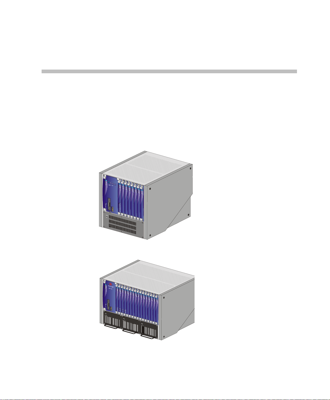
The MGC-50 and the MGC-100 are high performance, high capacity
Multipoint Contro l Units (MCU) which support up t o 48 ports for the MGC50, and 96 ports for the MGC-100. They utilize a variable port bandwidth
ranging from 56 to 1920 Kbps.
1
Figure 1-1: MGC 50
Figure 1-2: MGC 100
1-1
Page 12

Chapter 1 - Before You Begin
The system meets International Telecommunication Union Telecommunication Standardization Sector, (ITU-T, formerly CCITT)
standards for multipoint multimedia bridging devices, and meets ETSI
standards for telecommunication products. The MGC-100 DC also meets the
NEBS Compliant Standard (when so ordered) for our clients based in the
United States.
The flexible architecture in the system is designed to accommodate users’
changing multipoint needs. This system utilizes a modular “universal slot”
platform that allows the fo rma tion of di fferent configuratio ns based on u s ers’
individual port capacity and functionality requirements.
1-2
Page 13

MGC Unit Main Features
The MGC unit offers the following features:
• Supports a large number of ports (48 for the MGC-50, 96 for the MGC-
100) running at 128 Kbps
• Universal slots, telco grade high availability with hot-swappable
modules, redundancy, on-line upgrading and dynamic resource
allocation
• Support for standard network interfaces (ISDN, ATM, T1-CAS, LAN
and V.35 serial) for the easy integration of conference elements into
external network management and billing systems
• Support for up to 16 operator workstations (PCs) connected to either a
local or remote MCU; each operator workstation can be connected to
several MGC units
• Multirate conferencing and Transcoding (audio and video, including
high bit rate video and data bit rate conversion)
• Channel aggregation according to H.221, BONDING and Multirate (H0)
• Automatic rate detection upon endpoint connection to the conference
• H.320/H.323 video, T.120 data and Greet and Guide conferencing
• Enhanced Continuous Presence (multi-image video)
• IVR (Interactive Voice Response)
• Windows 95®/Windows 98®/Windows NT®/Windows 2000®/
Windows XP® based operator station
• Multiple operators per conference
• Multiple conferences and MCUs per operator
• TCP/IP - LAN - Internet access
• Supports serial communication (V.35/RS-530/RS-449) (optional)
MGC Hardware and Inst a llation Manual
1-3
Page 14
Chapter 1 - Before You Begin
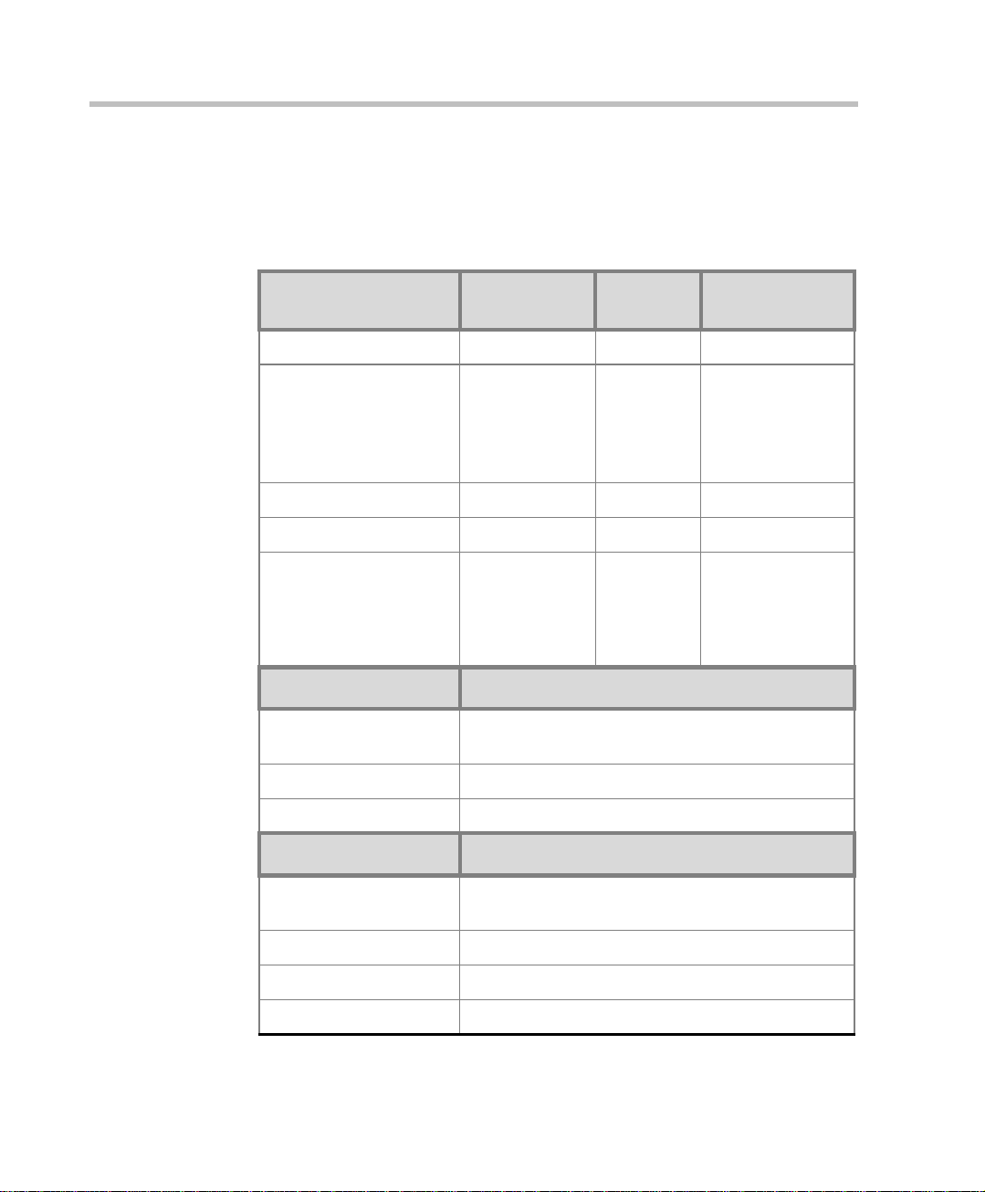
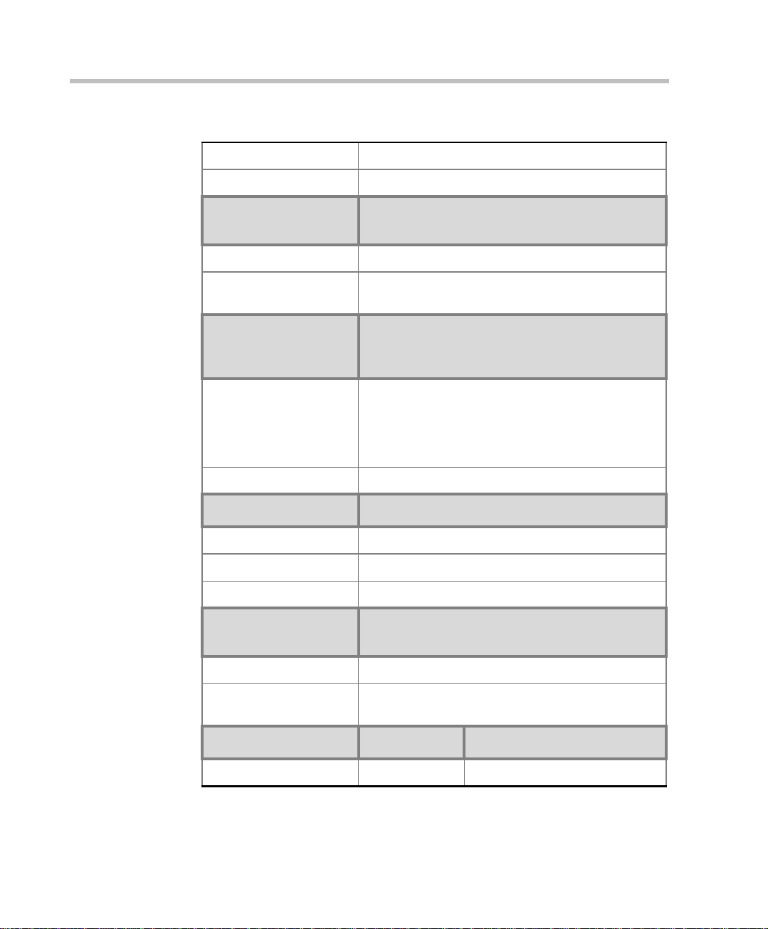
MGC-50/MGC-100 Specifications
Table 1-1 lists the specifications of the MGC-50 and the MGC-100 units.
Table 1-1: MGC Specifications
Physical MGC-50 MGC-100 MGC-100
Height 16” 16” 21”
NEBS
Width 15”, 19” with
mounting plate
Depth 19.5” 19.5” 19.5”
Weight Up to 24 kg Up to 48 kg Up to 58 kg
Free space ab ove the
MCU rack
IP Proto cols MGC-50/MGC-100
Audio G.711, G.722 (48), G.722.1, G.728, G.729A, G.
Video H.261, H.263 (Annexes N, F, P), H.264
Data T.120
H. 320 Protocols MGC-50/MGC-100
Audio G.711, G.722 (48), G.722.1, G.728, G. 723.1, Siren
3” in standard
installations
723.1, Siren 7, Siren 14
7, Siren 14
23” with
mounting
plates, 19”
with unit at
°
90
3” standard
installation,
9” if a MPI8 is to be
fitted
23” with mounting
plates
It is
recommended for
the installer to
refer to the NEBS
Standards
1-4
Video H.261, H.263 (Annexes N, F, P), H.264
Data T.120
Cascading H.243
Page 15
MGC Hardware and Inst a llation Manual
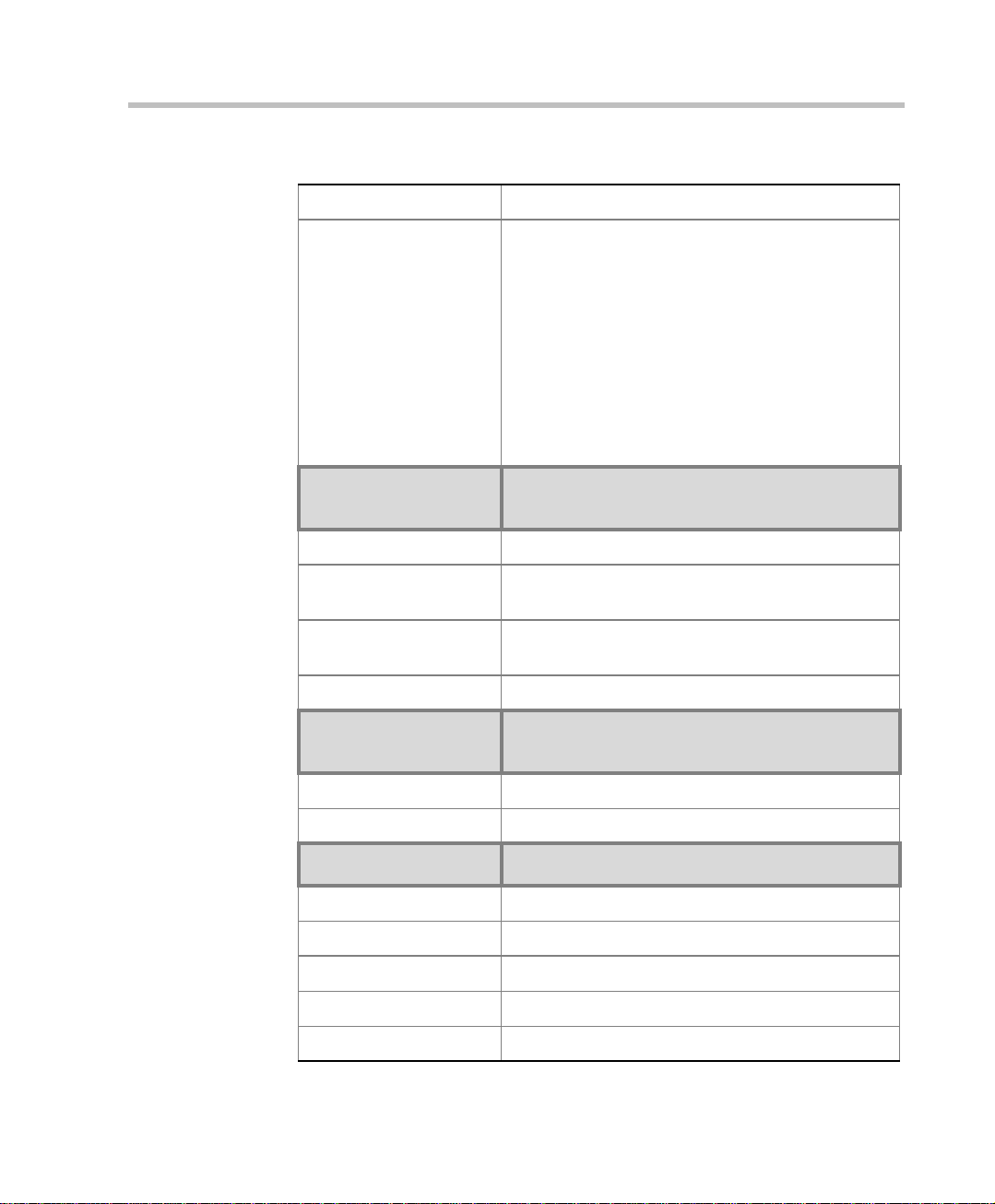
Table 1-1: MGC Specifications
Channel aggregation H.221, BONDING, Multi-Rate (H0)
Network interfaces ISDN:
T1 PRI, E1 PRI, Multirate ISDN, NFAS, Leased
lines-T1/E1, Switched 56
T1-CAS
T1-CAS lines for Audio Only connections
ATM:
25 (FVC.COM), 155 (FVC.COM)
IP (H.323 and SIP):
LAN
Serial:
V.35, RS449, RS530/A
External
Communications
MGC-50/MGC-100
Data rates 56 Kbps - 1920 Kbps (E1)
Network interfaces ISDN T1/ E1, A TM-25 (First V irtual), ATM-155 (First
Virtual), T1-CAS, LAN, serial (MPI)
MGC Manager control
connection
An independent LAN co nnection (sep arate from th e
Network connection)
Clock synchronization Synchronizes to external netw o rk
Local/Remote External
Equipment
MGC-50/MGC-100
Operator workstations LAN/RS-232/Modem/Internet
Reservation systems LAN/Internet/Modem
Environment MGC-50/MGC-100
Operating temperature 10°–40°C (50°–104°F)
Storage temperature -40°–70°C (40°–158°F)
Relative humidity 15%-90% no condensing
Operating altitude Up to approx. 3,000m (10,000ft)
Storage altitude Up to approx. 12,000m (40,000ft)
1-5
Page 16
Chapter 1 - Before You Begin
Table 1-1: MGC Specifications
Operating ESD +8kV
Storage ESD +15kV
System
Communications
Integrated scheduler Yes
API to 3rd party
reservation systems
Conference Setup
(Scheduled/
Unscheduled)
Meet Me Per
MGC-50/MGC-100
Yes
MGC-50/MGC-100
• Conference
• MCU
• Channel
• Party
Dial-out/Dial-in Yes
Diagnostics MGC-50/MGC-100
Power up Yes
On-line Yes
Remote Yes
Serviceability /
Reliability
MGC-50/MGC-100
1-6
Hot plug-in modules Yes
Front panel removable
modules
Power Supply MGC-50 MGC-100
DC Input - -48 VDC
Yes
Page 17
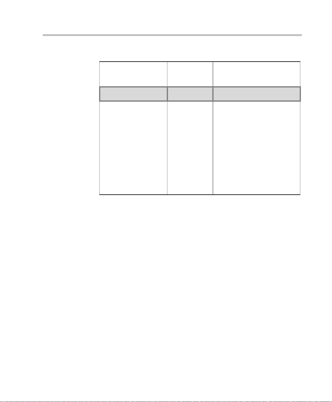
Table 1-1: MGC Specifications
MGC Hardware and Inst a llation Manual
AC Input 100-240 VAC,
50/60 Hz
100-240 VAC,
50/60 Hz
Power Consumption MGC-50 MGC-100
AC Maximum Power
consumption
AC Voltage 10Amp at 100
VAC, 5 Amp at
240 VAC
protected by a
12.5 Amp fuse.
Note: Older
MCU unit s may
have different
power ratings.
Contact your
AC Voltage - 8.5 Amp at 100
VAC and 4.2 Amp at 240 VAC
protected by a 15 Amp circuit
breaker.
DC Vol t ag e - 30 Am p at 4 8 VDC
protected by a 50 Amp circuit
breaker.
Note: Older MCU units may
have different power ratings.
Contact your next level of
support.
next level of
support.
1-7
Page 18

Chapter 1 - Before You Begin
Scope of Manual
This manual describes the MGC-50 and the MGC-100 hardware and
installation procedure. It is intended for service engineers, system
administrators and system operators who need to install, configure and
maintain the MGC unit.
Detailed information on using the system, including starting and shutting
down the system, is provided in the MGC Manager User’s Guide.
This manual assumes the user has the following knowledge:
• Familiarity with the Windows 95®, Windows 98®, Windows 2000®,
Windows NT®, and Windows XP® environment and interface
• Basic knowledge of videoconferencing concepts and terminology
The MGC Hardware and Installation Manual includes the following topics:
• Chapter 1 - Before You Begin
Provides a general description of the MGC unit, its main features and
description of the MGC Hardware and Installation Guide.
• Chapter 2 - MGC Unit Hardware Installation
Installing the MGC unit and connecting it to the operator workstations.
• Chapter 3 - System Architecture
Describes the system architecture and the data flow.
• Chapter 4 - Hardware Description
Describes the various components that make up the MGC unit.
• Chapter 5 - Maintenance
Describes the controls and LED indicators and provides maintenance
procedures.
• Appendix A - Int er f aces Pin Assignm ent
Describes the pinout of the various MGC unit connectors.
1-8
Page 19

Conventions
Before using this manual, it is important for you to understand the terms and
conventions used:
• The term “Choose” or “Double-click” is used when you need to activate
• The term “Select” or “Click” is used to highlight a part of the window,
• The term “Right-click” is used when you press and release the right
• The term “Choose OK” means that you can either click the OK button
• Keyboard keys appear in capital letters, between these two symbols
• The plus sign (+) between two key names indicates that you must press
• Bold type appearing in the text, or in a procedure indicates the word or
• Italic type appearing in the text or in a procedure indicates the menu
• Tips and notes appear in a different typeface and between two bars. For
MGC Hardware and Inst a llation Manual
a menu command or a command button in the dialog box.
dialog box or menu that you want to be changed with your next action.
mouse button to open a pop-up menu.
with the mouse, or press the <Enter> key on the keyboard.
< >. For example, the Shift key appears as <Shift>.
and hold down one key while pressing down the second key. For
example, “press <Alt>+<P> means that you press and hold down the Alt
key while you press the P key.
the character that you should type i nto a text bo x from the keyboar d. It is
also used to indicate the name of the menu name or command name that
you should select.
name, dialog box name or field name from which an option should be
selected or into which parameters should be entered.
example:
This is an example of notes that you may encounter throughout this Hardware
Manual.
1-9
Page 20
Chapter 1 - Before You Begin
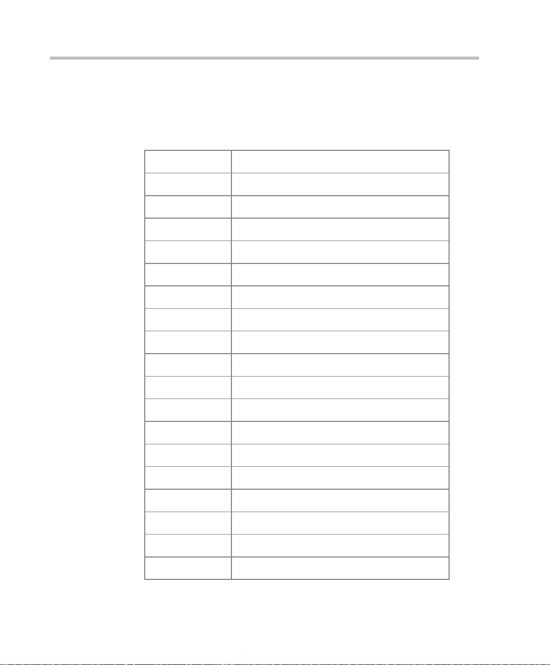
List of Abbreviations
The following is the list of abbreviations used throughout this manual:
Table 1-2: Abbreviations
API Application Programming Interface
CSU Channel Service Unit
DPR Dual Port Ram
ESD Electro-Static Discharge
HDLC High-level Data Link Control
HSD High Speed Data
IP Internet Protocol
ISDN Integrated Services Digital N etwork
1-10
LAN Local Area Network
LED Light Emitting Diode
LSD Low Speed Data
MCU Multipoint Control Unit
MGC Multimedia Gateway Control
MPI Multi Protocol Interface
MUX Multiplexor
PBX Private Branch Exchange
PRI Primary Ra te Interface
TCP Transmission Control Protocol
TDM Time Division Multiplexing
Page 21
MGC Hardware and Inst a llation Manual
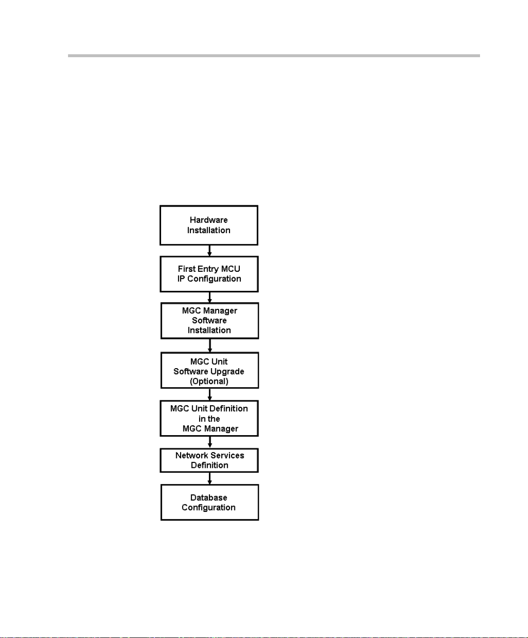
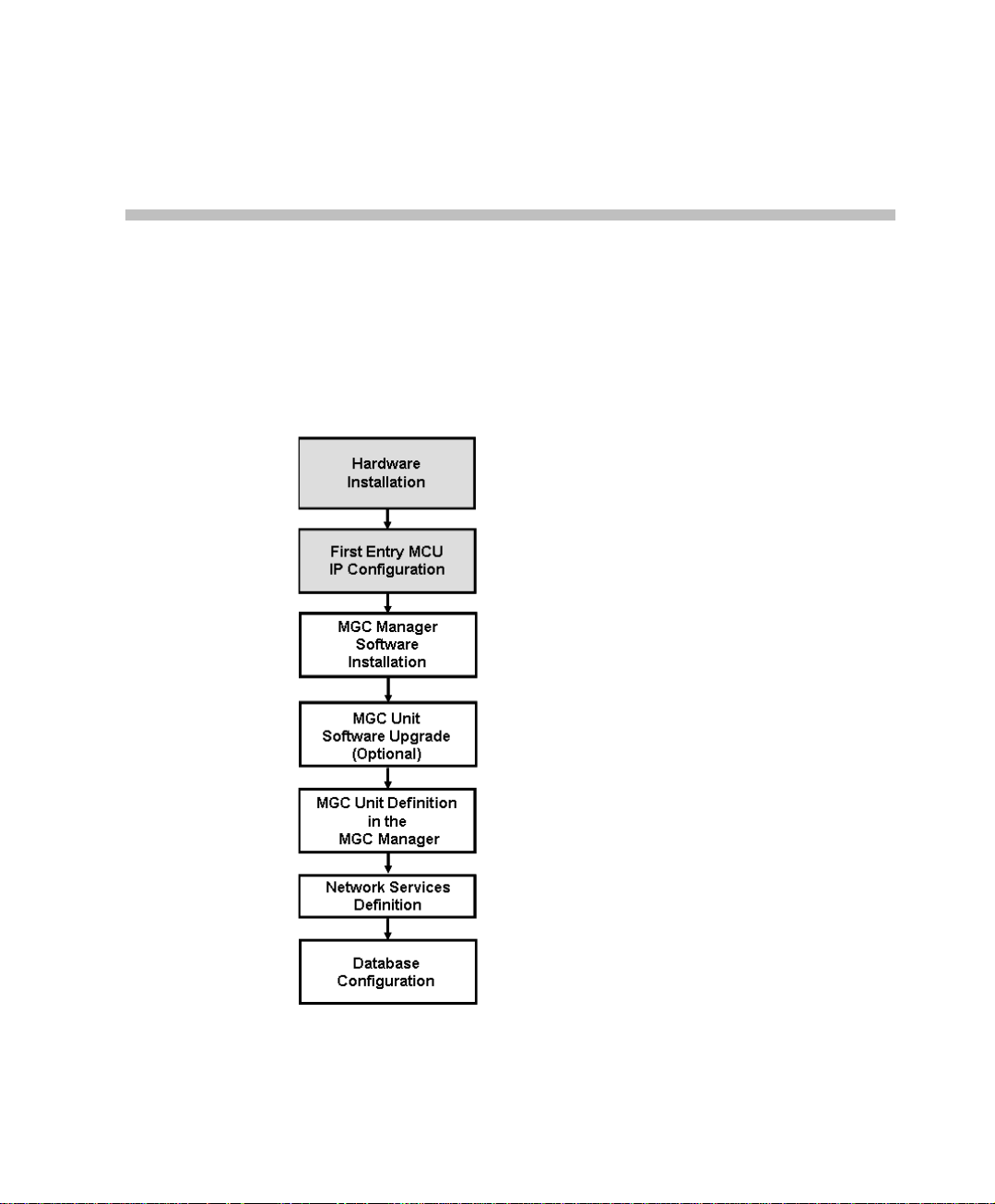
Insta ll ation and Configuration Workflow
The MGC unit installation and configuration process includes the following
main steps: Hardware Installation, Software Installation, Database
Configuration, Network Services definition and the MGC unit cards
configuration. The Hardware Inst al l ation stage is described in t his gui de . Th e
remaining steps are described in the MGC Administrator’s Guide, as
described in following flowchart.
MGC Hardware and Installation Manual,
Chapter 2
MGC Hardware and Installation Manual,
Chapter 2
MGC Administrat or’s Guide,
Chapter 2
MGC Administrat or’s Guide,
Chapter 2
MGC Administrat or’s Guide,
Chapter 2
MGC Administrat or’s Guide,
Chapter 3
MGC User’s Guide - Volume II,
Chapter 6
Figure 1-3: Installation and Configuration Workflow
1-11
Page 22

Chapter 1 - Before You Begin
1-12
Page 23
Hardware Installation
This chapter describes the unpacking and connection of both the MGC+50
and the MGC+100, to the ISDN, T1-CAS, H.323, MPI or serial network to
the operator workstation (P C)
MGC Hardware and Installation Manual,
Chapter 2
MGC Hardware and Installation Manual,
Chapter 2
MGC Administrat or’s Guide,
Chapter 2
2
MGC Administrat or’s Guide,
Chapter 2
MGC Administrat or’s Guide,
Chapter 2
MGC Administrat or’s Guide,
Chapter 3
MGC User’s Guide - Volume II,
Chapter 6
Figure 2-1: Installation and Configuration Workflow - Hardware Installation
2-1
Page 24
Chapter 2 - Hardware Installation
C
MGC-100 Hardware Installation
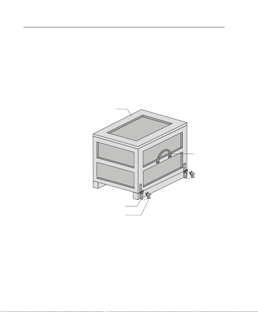
Unpacking and Positioning the MGC-100
To unpack and position the MGC-100:
1. When you receive your MGC-100, inspect the equipment for damage
and verify that the components match the packing slip. If you did not
receive a component or if there is damage to the system, notify your
service representative immediately.
Wood Packing
Lock in Closed Position
Lock in Open Position
Figure 2-1: MGC-100 package
ase
Carrying Strap
2. Place the MGC-100 unit on a stable flat surface in a location that meets
the MGC environment requirements, which are:
2-2
• Operating temperature: 10°–40°C (50°–104°F)
• Humidity: 15%–90% non-condensing
• Altitude: Up to 3,000m (10,000ft)
• ESD: +8 kV
Page 25
MGC Hardware and Installation Manual
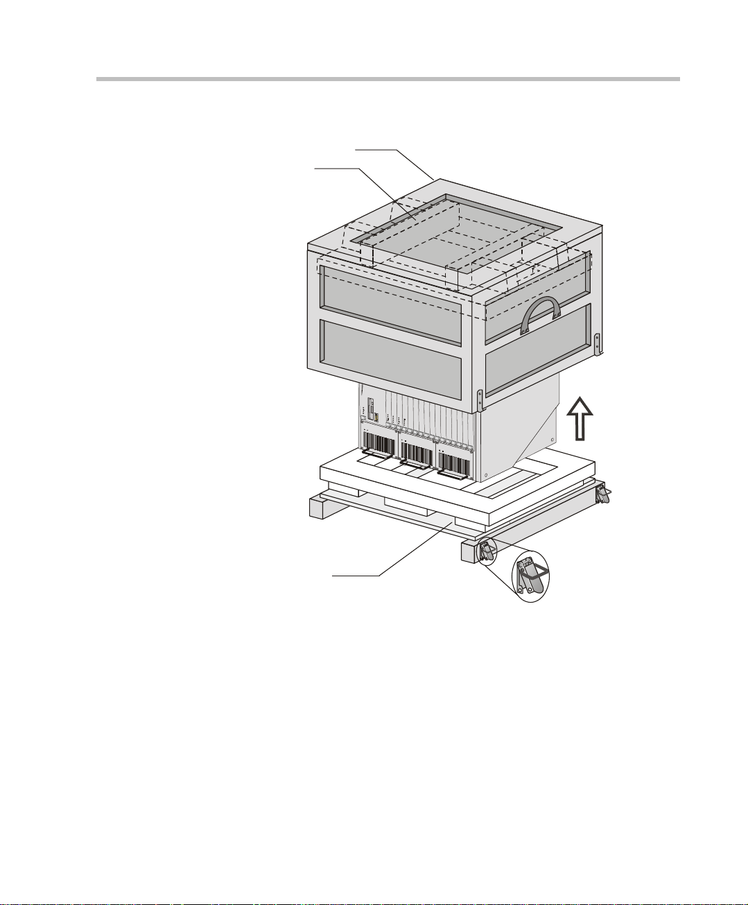
C
3. Release the clasp locks at the bottom, and lift the MGC-100 top cover.
Wood Packing
Foam Block
ase
Foam Block
Figure 2-2: Unpacking the MGC-100
4. Lift the MGC-100 unit and remove the packaging material.
5. Lower the MGC-100 unit, placing it on the surface.
If the MGC-100 is a standalone unit, place it on a flat surface. If you are
rack mounting the MGC-100, allow a minimum clearance of 3” above
the unit. If you are rack mounting the NEBS MGC-100, the 3” above the
unit is not needed. Refer to the NEBS Standards for clearance
compliance.
2-3
Page 26
Chapter 2 - Hardware Installation
e
Mounting the MGC-100 on a 23” Rack
The MGC-100 can be mounted to a 23” rack using the two mounting plates
that are pre-installed on the unit.
1. Make sure that the MCU is turned OFF and it is disconnected from the
AC or DC power.
2. Place the MCU in a 23” rack and support it, screw the mounting brackets
to the rack securing it with bolts and
self-locking nuts (which the client provide s).
-orIf the MGC-100 was shipped without the two mounting plates that are
usually pre-installed:
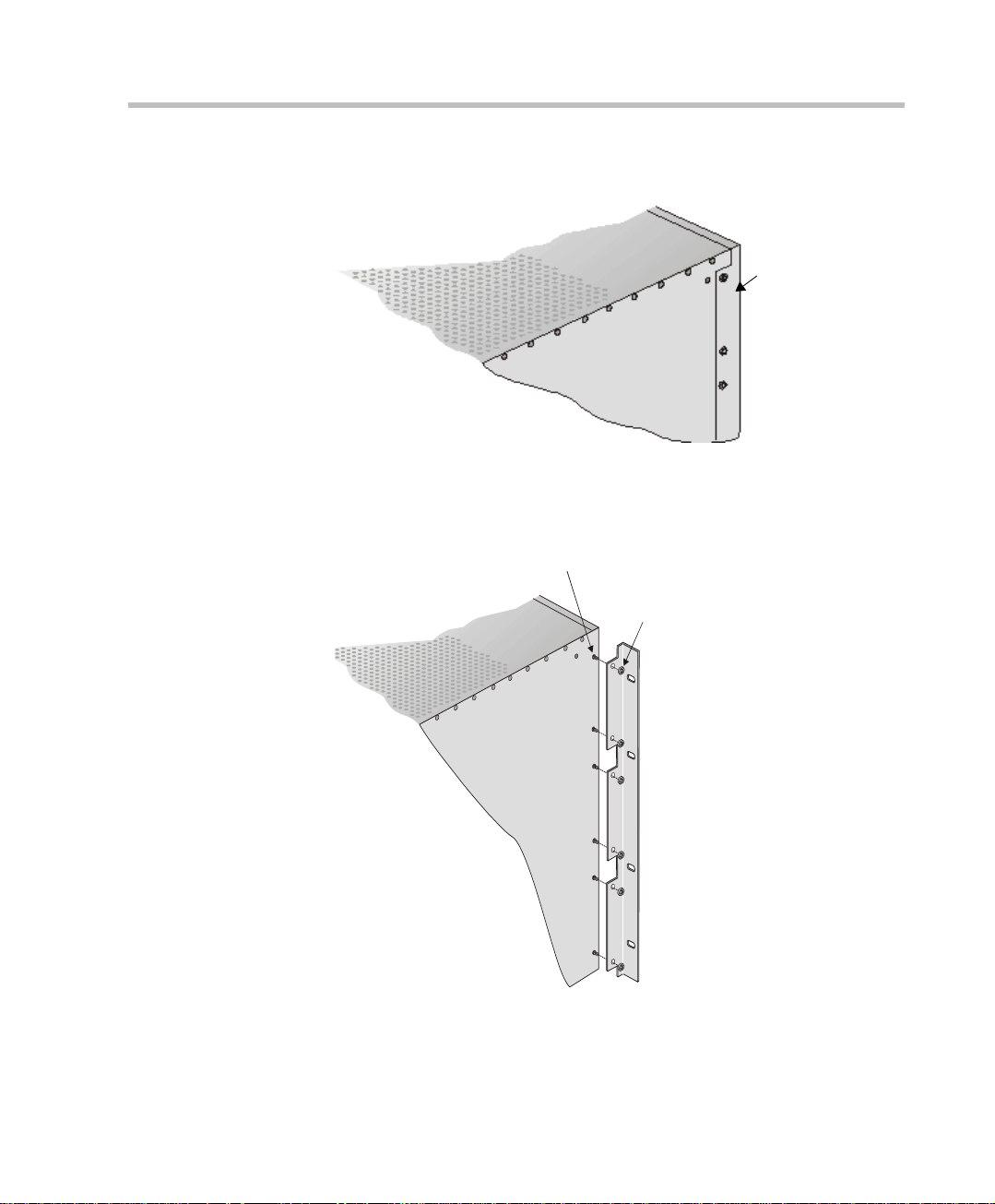
1. Make sure that the MCU power is turned OFF and that it is disconnected
from the AC or DC power.
2. With a slotted screwdriver remove the five nylon plug hole covers from
the MCU side covers.
3. With an Allen wrench (M4), remove the five screws from the MCU side
covers.
2-4
4. Remove both MCU side c overs.
front
remov
screws
rear
5. Remove the plates from the both sides of the MGC by removing the
appropriate number of functional modules to allow access to the screws.
Page 27
MGC Hardware and Installation Manual
t
6. Unscrew both MCU the side screws and remove both side plates.
front
Remove
plate
7. From the inside of the MGC-100, screw the mounting brackets to both
sides of the MCU, securing the screws in the mounted nuts.
Screw mounting
plate from the
inside of the MGC
(Front)
Secure with nu
2-5
Page 28
Chapter 2 - Hardware Installation
r
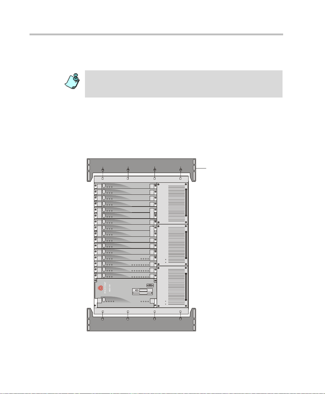
8. Place the MCU in a 23” rack and while su pporting it , screw t he mounting
brackets to the rack sec uring it with bolts and self-locking nuts.
When the unit is installed on a rack, the rack must be properly grounded to the
central office ground. The rack must be grounded with two-hole compressiontype connectors using copper conductors (tinned or untinned). Wire, bus bar or
braided strap connectors are acceptable.
Mounting the MGC-100 on a 19” Rack
The MGC-100 can be mounted in a 19” rack using the mounting kit (P/NKIT2026A). It is highly recommended that the 19” rack be located in an airconditioned room.
Figure 2-3 shows how to mount the MGC-100 on the 19” rack.
Stby
Fail
Active
AUDIOAUDIO
Stby
Fail
Active
Stby
Fail
Active
19" Attachment Ba
2-6
Stby Stby
Fail Fail
Active Active
Stby
Fail
Active
Stby Stby
Fail Fail
Active Active
Stby
Fail
Active
Stby Stby
Fail Fail
Active Active
Stby
Fail
Active
MUX M UX DATA DATA VIDEO VIDEO VIDEO AUDIOVIDEO AUDIO
Stby
Fail
Active
NET-E1
Stby
Fail
Active
Stby
Fail
Active
NET-8NET-8 NET-8
Stby
Fail
Active
Major
Minor
L0
Critical
CONT
Line A
Line B
Line 6
Line 7
Line 8
Line 3
Line 4
Line 5
Line 1
Line 2
Line 6
Line 7
Line 8
Line 3
Line 4
Line 5
Line 1
Line 2
Line 6
Line 7
Line 8
Line 1
Line 2
Line 3
Line 4
Line 5
PowerL1L2
L3
Figure 2-3: MCU Rack Mount
OUT
PWR
IN
OUT
PWR
IN
OUT
PWR
IN
Page 29
MGC Hardware and Installation Manual
Because of heat conside rations, t he MCU must be inst alled with the C ontrol Un it
Module placed on the left bo ttom.
1. Check that all the parts are in the kit.
The kit should contain the following items:
Table 2-1: 19” Rack Mounting Kit
Item # Polycom P/N Description Quantity
1 MEC2063A 23" TO 19" Mounting Bar MGC-
100 at 90 Degrees
2 SCR2005A Screw 10-32 x 1/2” Allen S/H
ST/ST
3 WAS2003A Washer M5 Spring Latch Loc.
ST\ST
4 WAS2004A Washer M5 Flat ST/ST 8
2
8
8
2. Make sure that the MCU power is turned OFF and it is disconnected
from the AC and DC power.
Remove the side covers as described on page 2-4.
3. If the MCU is a standalone unit, you must first remove the side covers,
and add the mounting brackets to a 23” rack (see pages 2-4 to 2-6).
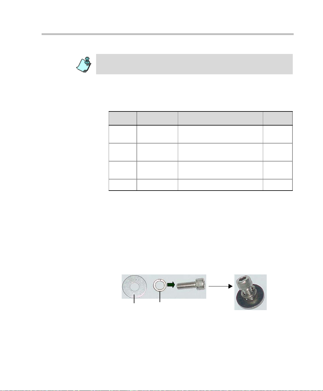
4. Attach the two mounting bars to the MCU as follows:
a. Fit the sprin g washer (Item #3) onto the screw (#2).
b. Fit the flat washer (Item #4) onto the screw.
Item #4
Item # 3
c. Take the two mounting bars (Item #1) from the kit and attach them
to the MGC-100 unit with the screws (with the attached washers, as
described in step b).
2-7
Page 30
Chapter 2 - Hardware Installation
5. Carefully rotate the MGC-100 counterclockwise 90°, making sure the
Control Unit is at the bottom left.
6. While supporting the MGC-100, place it on the 19” rack and screw the
brackets to the rack, securing it with the screws and nuts supplied with
the rack.
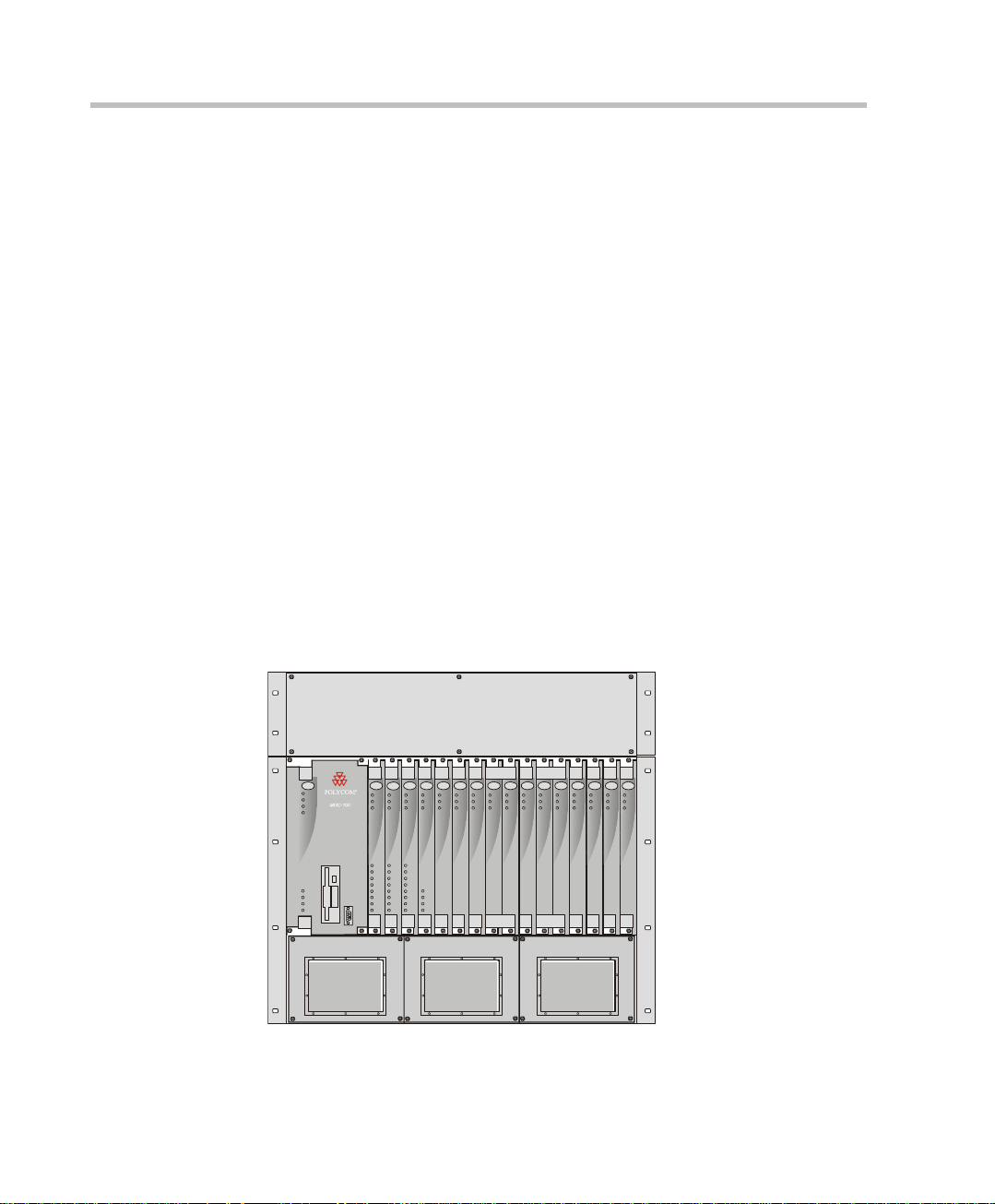
NEBS Standard
For installations based within the United States, an MGC-100 DC NEBS
compliant system is available. The NEBS compliant systems differs in its
construction of the frame and the power supply. All else remains the same.
The construction of the MGC-100 is 12 U’s, (1 U = 4.3 cm) which makes it
higher by 3 U’s than the original frame of the MGC-100. This design allows
for a cushion of air to be present, ensuring safety in case of a heat related
problem.
In addition, the power supply is also designed differently by allowing the
circulation of cool air, providing a safety tolerance in case of a heat related
problems.
Use only shielded LAN cables where the shield is grounded at both ends
when connecting to the IO LAN port of the IP+48 on the MGC+ rear panel.
2-8
CONT
Critical
Major
Minor
L0
Power
L1
L2
L3
NET-E1
MUX MUX DATA DATA VIDEO VIDEO VIDEO AUDIOVIDEO AUDIO
NET-8NET-8 NET-8
Stby
Stby
Stby
Fail
Active
Line 1
Line 2
Line 3
Line 4
Line 5
Line 6
Line 7
Line 8
Stby
Stby Stb y
Stby
Stby Stb y
Stby
Stby
Fail
Fail
Fail
Fail Fail
Fail
Active
Active
Active
Line 1
Line 1
Line 2
Line 2
Line 3
Line 3
Line 4
Line 4
Line 5
Line 5
Line A
Line 6
Line 6
Line 7
Line 7
Line B
Line 8
Line 8
Fail
Active
Active Act ive
Active
Fail Fail
Active Act ive
Stby Stby
Fail
Fail Fail
Active
Active Active
Figure 2-4: NEBS Standard Unit Front View
AUDIOAUDIO
Stby
Stby
Stby
Fail
Fail
Fail
Active
Active
Active
Page 31

Connecting and Setting Up the MGC-100
S
Use the MGC-100 rear panel diagram below for reference.
lot A
RS232
Connectors
MUSIC
LINE IN
Network
Connectors
MGC Hardware and Installation Manual
Main Control
Module Cover
Main Switch
and Circuit Breaker
AC Inlet
COM
Dry Contacts RJ45 Connector
ALARMSCOM 1
LAN
10/100 Mbits
Fan
Figure 2-5: MGC-100 Rear Panel with External Connectors
T o connect the MGC-100 to the network and power source and set up the
system the following procedures are performed:
• Connecting the MGC unit to t he power source (A C inlet or - 48DC power
distribution unit)
• Connecting the MGC unit to the LAN Network
• Connecting the MGC unit to the Operator Workstation (PC) directly via
RS-232 (optional)
• Connecting the MGC unit to the network(s)
2-9
Page 32

Chapter 2 - Hardware Installation
MGC-100 Dongle
MGC-100 is shipped with a serial dongle installed on COM1 on the MCU
rear panel. The dongle is required for normal operation of the MCU. If the
dongle is missing, please contact support.
Connecting to the power source
Y ou can conn ect to an AC Inlet or to DC power supply according to t he power
system used in your site. Follow the steps appropriate to your power system.
The following restrictio ns apply to the c onducto rs and connectors t hat may be
used to ground the unit when rack mounted:
• When using bare conductors, they must be coated with an appropriate
antioxidant compound before crimp connections are made. Tinned,
solder-plated or silver-plated connectors do not have to be prepared in
this manner.
• The same bolt assemblies should not secure multiple connectors.
• Listed fastening hardware must be compatible with the materials being
joined and must be preclude l oosening, deteri oration and e lectrochemical
corrosion of the hardware and joint materials.
2-10
To connect to the AC Inlet:
1. Make sure the power switch is OFF. Insert the power cable into the
power connector on the rear panel of the MGC-100 unit.
Main Switch
AC Inlet
2. Insert the power cable into the power source socket.
3. Turn on the power by pressing on the power switch located on the rear
panel of the MGC-100 unit.
Page 33

MGC Hardware and Installation Manual
To connect to the -48DC power system:
1. Make sure the power switch is OFF. Turn off the DC power distribution
unit.
2. Using the three wires 10 AWG cable running from the DC power
distribution unit, connect the black wire into the -48IN terminal block
and the red wire to the -48V RTN terminal block.
3. Connect the green or green-yellow wire to the system single-point
“Ground” screw.
COM
Ground
ON
OFF
+
-48VIN-48V
ON
OFF
RTN
+
-48V
-48V
IN
RTN
If the unit is rack mount ed, t he si ngl e-point ground on the MCU must be
connected to the rack with a single conductor and attached as to prevent
loosening.
When using bare conductors, they must be coated with an appropriate
antioxidant compound before crimp connections are made. Tinned,
solder-plated or silver plated connectors do not have to be prepared in
this manner.
4. Turn on the DC power distribution unit.
2-11
Page 34

Chapter 2 - Hardware Installation
5. Turn on the power by pressing on the power switch located on the rear
panel of the MGC-100 unit.
Connecting the MGC-100 to the LAN Network
Connect one end of a network cab le to t he LAN conne ctor on the rear panel of
the MGC-100 and the other end to the network.
Connecting the MGC-100 to the Operator Workstation (PC) Directly via RS-232 (Optional)
Connect one end of an RS-232 cable to the COM2 connector on the front
panel of the MGC-100 Control Unit and t he ot her end to the ser ia l port of the
operator station (see RS-232 Pin Assignment, A-3).
2-12
Page 35

MGC Hardware and Installation Manual
Connecting the MGC-100 to the Network
To connect the MGC-100 to the ISDN network or T1-CAS Network:
The ISDN network is opt ional. If the MG C-10 0 has t o be co nne cted to the publ ic
ISDN network then an external CSU or similar equipment is needed.
T1-CAS network is optional. It allows you to connect Audio Only participants to
conferences via T1-CAS lines. It uses the same network connections as ISDN
and the procedure described below is applicable to both ISDN and T1-CAS
lines.
• Connect the 8-pin RJ-45 connector of the network cable to the NET
RJ-45 jack on the rear panel of the MGC-100. Repeat this step for each
of the ISDN network lines to be connected to the Network Interface card
installed in the MCU.
ISDN network
connection
Figure 2-6: ISDN network connection
ISDN Network connection
for 4 spans
ISDN Network connection
for 8 spans
Leased lines should be connected using an adapter with a screw
connector with solid conductor wires or a similar adapter.
• Connect one side of the adapter to the NET RJ-45 jack on the rear panel
of the MGC-100. Then connect the leased line wires to the other side of
the adapter.
The ISDN and T1-CAS network properties must be defined in the Network
Services. For details, see the MGC Administrator’s Guide, Chapter 3.
2-13
Page 36

Chapter 2 - Hardware Installation
To connect the MGC-100 to the ATM network:
The MGC-100 can be connected to an ATM network. The type of connection
being used differs according to the ATM Network Interface card installed in
the MCU.
If an ATM-25 network interface card is installed, connect the 8-pin
RJ-45 connector of the net work ca ble t o the NE T RJ-45 jack on t he rear p anel
of the MGC-100.
Figure 2-7: ATM-25 network connection
2-14
If an ATM-155 network interface card is installed, first remove the rubber
plug covering the jack. Then connect the fiber optics cable connector to the
jack on the rear panel of the MGC-100.
Figure 2-8: ATM-155 network connection
The A TM net work properties must be defined in the N etwork Servic es, For more
details, see the MGC Administrator’s Guide, Chapter 3.
Page 37

MGC Hardware and Installation Manual
To connect the MGC-100 to the IP network:
If an IP network Interface card is instal led in the MGC-100, conn ect t he 8-pin
RJ-45 connector of the LAN networ k cable to the LAN-32 3 RJ-45 jac k on the
rear panel of the MGC-100.
Figure 2-9: LAN H.323 network connecti on
When installing a NEBS complia nt system, use only shield ed LAN cables where
the shield is grounded at both ends when connecting to the IO LAN port of the
IP+48 on the MGC+ rear panel.
The IP network properties must be defined in the IP Network Service. For
details, see MGC Administrato r’s Guide, Chapter 3.
2-15
Page 38

Chapter 2 - Hardware Installation
MPI-4/8 Hardware Installation for the MGC-100
The MPI-4/8 (Multi Protocol Interface) Network Interface card is inserted
into the MGC-100 unit.
The MPI box may be mounted on top of the MGC-100 using mounting
brackets, or on a separate 19” or 23” rack, as can be seen in Figure 2 -8. When
installed on a 19” rack, the MPI box can be mounted directly on the rack.
When installed on a 23” rack, a mou nting plate must be used. If th e MGC-100
is rack mounted, there must be at least 6” free space above the MGC-100 to
be able to install the MPI Box on top of the MGC unit.
MPI Box
in 19" Rack
2-16
Mounting
Plate
CONT
MG-323
VIDEOVIDEO VIDEOVIDEOAUDIOAUDIO
PRI-8
ACCORD
Critical
Stby
StbyStby
StbyStbyStby
Stby
Stby
Major
Fail
FailFail
FailFailFail
Fail
Fail
Minor
MGC-50
Active
ActiveActive
ActiveActiveActive
Active
Active
L0
Line 1
Line 2
Line 3
Line 4
Power
Line 5
L1
Line 6
L2
Line 7
Line 8
PWR
OUT
Figure 2-10: MPI Box rack mounting options
Page 39

MGC Hardware and Installation Manual
To install the MPI-4/8 Network Interface Module:
1. Slide the MPI-4/8 Network Interface module into a free slot in the MGC
front panel.
2. Push the MPI-4/8 Network Interface module firmly into the Backplane,
making sure it is properly seated in its slot.
3. Tighten the screws on the front panel of the MGC-100 that secure the
MPI-4/8 Network Interface module.
To install the MPI Box on Top of the MCU:
1. Turn OFF power to the MCU and unplug it from AC power.
2. If the MCU is rack mounted, disconnect all the external cables, dismou nt
the MCU from the rack and place it on a desktop or work table.
If it is a standalone unit, remove the MCU side panels.
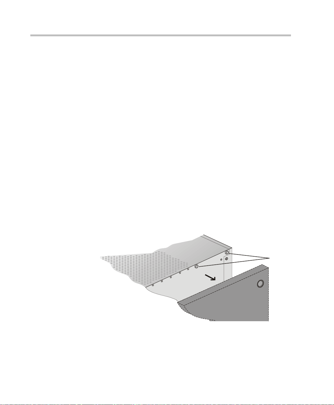
3. Remove the two Phillips screws on each side of the MCU (near the rear
panel).
rear
front
remove
screws
2-17
Page 40

Chapter 2 - Hardware Installation
r
4. Place the mounting bracket on top of the MCU aligning it against the
screw openings as shown below and tighten the screws.
5. Mount the bracket on the other side of the MCU (repeat step 4).
6. Place the MPI box with its four 160-pin connectors facing the MCU front
panel between the two mounting brackets. Secure it with the screws
supplied with the MPI B ox.
rear
tighten
screws
front
2-18
rea
front
Page 41

MGC Hardware and Installation Manual
7. If the MCU is standalone, reassemble the side panels.
If the MCU is rack mounted, mount the unit on the rack and connect all
the external cables.
PORTS
1-4
PORTS
5-8
NET-8
CONT
Critical
Major
MGC-100
Minor
L0
NET-E1 MPINET-8 NET-8
Stby
Fail
Active
MPI
Stby
Stby
Stby
Stby
Stby Stby
Fail
Fail
Fail
Fail
Fail Fail
Active
Active
Active
Active
Active Active
DATA
DATA VIDEO VIDEO
Stby
Stby St by
Fail
Fail Fail
Active
Active Active
PORTS
9-12
PORTS
13-16
VIDEO AUDIOVIDEO AUDIO
Stby
Stby St by
Fail
Fail Fail
Active
Active Active
AUDIOAUDIO
Stby
Stby
Stby
Fail
Fail
Fail
Active
Active
Active
ABA
Line 1
Line 1
Line 1
Line 2
Line 2
Line 2
Line 3
Line 3
Line 3
Line 4
Line 4
Line 4
Power
Line 5
Line 6
L1
Line 7
L2
Line 8
L3
PWR
IN OUT
B
Line 5
Line 5
Line A
Line 6
Line 6
Line 7
Line 7
Line B
Line 8
Line 8
PWR
IN OUT
PWR
IN OUT
8. Using the cable provided with the MPI kit, connect the 160-pin
connector to Port A of the MPI-8 Network Interface front panel. C onnect
the other end of the cable to a (Ports 1-4) 160-pin connector of the MPI
Box; by doing this procedure we have utilized the MPI Box as a MPI-4.
9. Using a second cable, connect the angled 160-pin connector to Port B of
the MPI-8 Network Interface front panel. Connect the other end of the
cable to B (Ports 5-8) 160-pin connector of the MPI Box.
Using this procedure we have utilized the MPI Box as a MPI-8.
PORTS
1-4
PORTS
5-8
PORTS
9-12
PORTS
13-16
CONT
NET-8
Critical
Major
Minor
L0
MGC-100
Stby
Stby
Fail
Fail
Active
Active
DATA
DATA VIDEO VIDEO
VIDEO AUDIOVIDEO AUDIO
MPI
MPINET-8 NET-8
NET-E1
Stby
Stby
Stby
Stby St by
Stby
Stby Stby
Fail
Fail
Fail
Fail Fail
Active
Active
Active
Active Active
Stby
Fail
Fail Fail
Fail
Active
Active Activ e
Active
Stby Stby
Fail Fail
Active Active
AUDIOAUDIO
Stby
Stby
Stby
Fail
Fail
Fail
Active
Active
Active
ABA
Line 1
Line 1
Line 1
Line 2
Line 2
Line 2
Line 3
Line 3
Line 3
Line 4
Line 4
Power
L1
L2
L3
PWR
OUT
IN
Line 4
Line 5
Line 5
Line 6
Line 6
Line 7
Line 7
Line 8
Line 8
B
Line 5
Line A
Line 6
Line 7
Line B
Line 8
PWR
OUT
IN
PWR
OUT
IN
2-19
Page 42

Chapter 2 - Hardware Installation
10. Connect the serial cabl e running from the DCE to the appr opr i at e 37-pin
connector on the rear panel of the MPI Box. If dialing is used, connect
the appropriate cable from the DCE to the 25-pin connector on the rear
panel of the MPI Box.
Whenever the MGC unit is used as a DCE and connected straight to an
endpoint the serial data stream flows from the endpoint (DTE) through
the serial connector to the MPI box. The connections stay the same,
meaning; the endpoint is connected to the back of the MPI b ox by way of
the 37-pin connector , and t he other side of t he MPI box is then co nnected
by way of the 160-pin connector to the MPI card in the MGC unit. For
more information, refer to Chapter 4, “The MPI-8 Network Interface
Module” on page 4-39.
• If V.35 or RS-530 cable is used, att ach the special adapter (p rovided wit h the
kit) to the 37-pin prior to connecting the serial cable from the DCE.
• The serial (MPI) network properties must be defined in the Network
Services, For details, see MGC Administrator’s Guid e, Chapter 3.
2-20
Page 43

MGC-50 Hardware Installation
C
Unpacking and Positioning the MGC-50
To unpack and position the MGC-50:
1. When you receive your MGC-50, inspect the equipment for damage and
verify that the components match the packing slip. If you did not receive
a component or if there is damage to the system, notify Po lycom
immediately.
Wood Packing
ase
MGC Hardware and Installation Manual
Carrying Strap
Lock in Closed Position
Lock in Open Position
Figure 2-11: MGC-50 package
2. Place the MGC-50 unit on a stable flat surface in a location that meets
the MGC-50’s environment requirements, which are:
— Operating temperature: 10°–40°C (50°–104°F)
— Humidity: 15%–90% noncondensing
— Altitude: Up to 3,000m (10,000ft)
— ESD: +8 kV
2-21
Page 44

Chapter 2 - Hardware Installation
3. Release the clasp locks at the bottom, and lift the MGC-50 top cover.
ood Packing Case
oam Blocks
2-22
oam Blocks
Figure 2-12: Unpacking the MGC-50
4. Lift the MGC-50 unit and remove the package base.
5. Lower the MGC-50 unit, placing it on the surface.
If you are rack mounting the MGC-50, allow a minimum clearance of 3
inches above the unit.
Page 45

Mounting the MGC-50 on a Rack
e
The MGC-50 can be mounted in a 19” rack using two mounting plates (Kit
2012A). The side plates are usually mounted when shipped, but i f not , f oll ow
the directions below to install the mounted plates on the MGC-50 and then
mount the MGC-50 on the 19” rack.
To install and mount the MGC-50:
1. Make sure that the MGC-50 power is turned OFF and it is disconnected
from the AC power.
2. Remove the five nylon plug hole covers from the MGC-50 protective
side covers (using a slotted screwdriver).
3. Using an Allen wrench (M4), remove the five screws from the MGC-50
side covers.
4. Remove the MGC-50 side covers from both sides.
MGC Hardware and Installation Manual
front
remov
screws
rear
5. To remove the plate from bot h MGC-50 sides, t he side screws hav e to be
removed. To remove the screws from the left side the main control
module and the power supply must be removed first. These procedures
are described in Chapter 5 of this manual. For detailed procedures, see
Chapter 5, “Replacing the Main Control Module” on page 5-17. For
instructions on how to remove the power supply see Chapter 5,
“Replacing the Power Supply Module for the MGC-50” on page 5-12.
2-23
Page 46

Chapter 2 - Hardware Installation
6. Once the Main Control Module, the power supply modul e and the boards
are removed, unscrew the side screws from inside the MGC-50, and then
remove the plate from both MGC-50 sides.
7. From the inside of the MGC-50, screw the mounting bracket to the side
of the MGC-50, securing the screws in the mounted nuts.
Front
Remove
plate
Rear
Screw mounting
plate from the
inside of the MGC
(Front)
2-24
Page 47

MGC Hardware and Installation Manual
8. To remove the plate from the right side of the MGC unit remove the
appropriate number of functional modules to allow access to the screws.
9. From the inside of the MGC-50, screw the mounting bracket to the side
of the MGC-50, securing the screws with the mounted nuts.
10. Insert the functional modules removed earlier into the MGC-50.
11. Mount the P ower S upply module and M ain C ontro l Modu le back i n t heir
place as described in Chapter 5, “Replacing the Main Control Module,”
page 5-18 and “Replacing the Power Supply Module,” page 5-12.
12. Place the MGC-50 in a 19” rack and while supporting it, screw the
mounting brackets to the rack securing it with nuts.
MGC-50
in 19" Rack
ounting
Plate
CONT
PWR
OUT
VIDEOVIDEO VIDEOVIDEOAUDIOAUDIOMG-323PRI-8
ACCORD
Critical
Stby
StbyStby
StbyStbyStby
Stby
Stby
Major
Fail
FailFail
FailFailFail
Fail
Fail
Minor
MGC-50
Active
ActiveActive
ActiveActiveActive
Active
Active
L0
Line 1
Line 2
Line 3
Line 4
Power
Line 5
L1
Line 6
L2
Line 7
Line 8
2-25
Page 48

Chapter 2 - Hardware Installation
Connecting and Setting Up the MGC-50
Use the MGC-50 rear panel diagram below for reference.
Main Control
Module Cover
IO Card
COM 1
Fuse
Main Switch
AC Inlet
Connector
RJ45
LAN
Fan
Figure 2-13: MGC-50 Rear Panel with External Connectors
To connect the MGC-50 to the network and power source and set up the
system the following procedures are performed:
• Connecting the MGC unit to the power source (AC inlet)
• Connecting the MGC unit to the LAN Network
• Connecting the MGC unit to the Operator Workstation (PC) directly via
RS-232 (optional)
• Connecting the MGC unit to the network(s)
MGC-50 Dongle
2-26
MGC-50 is shipped with a seri al don gl e installed on COM1 on the MCU rear
panel. The dongle is requi red f or normal oper ati on of th e MC U. If the dongle
is missing, please contact support.
Page 49

MGC Hardware and Installation Manual
Connecting to the Power Source
To connect to the AC Inlet:
1. Make sure that the power switch located on the rear panel of the MGC
unit is off.
2. Insert the power cable into the power connector on the rear panel of the
MGC-50 unit.
Main Switch
AC Inlet
3. Insert the power cable into the power source socket.
4. Turn on the power by pressing on the power switch located on the rear
panel of the MGC-5 0 u nit.
If the unit is rack mount ed, the si ngle-po int g round o n the MCU-50 must
be connected to the rack with a single conductor and attached so that it
prevents loosening.
The following restrictions apply to the conductors and connectors that
may be used to ground the unit when rack mounted:
— When using bare conductors, they must be coated with an
appropriate antioxidant compound before crimp connections are
made. Tinned, solder-plated or silver plated connectors do not have
to be prepared in this manner.
— Multiple connectors should not be secu re d with the same bolt
assemblies.
— Listed fastening hardware must be compatible with the materials
being joined and must avoid loosening, deterioration and
electrochemical corrosion of the hardware and joint materials.
2-27
Page 50

Chapter 2 - Hardware Installation
Connecting the MGC-50 to the LAN Network
Connect one end of a network cab le to t he LAN conne ctor on the rear panel of
the MGC and the other end to the network.
Connecting the MGC-50 to the Operator Workstation (PC) Directly via RS-232 (Optional)
Connect one end of an RS-232 cable to the COM 2 connector on the front
panel of the MGC Control Unit and the other end to the serial port of the
operator station (See RS-232 Pin Assignment, A-3).
Connecting the MGC-50 to the Network
To connect the MGC-50 to the ISDN network and T1-CAS network:
2-28
This is an optional Network Interface Card. If the MGC-50 has to be connected
to the public ISDN network then an external CSU or where required, similar
equipment is needed.
T1-CAS network is optional. It allows you to connect Audio Only participants to
conferences via T1-CAS lines. It uses the same network connections as ISDN
and the procedure described below is applicable to both ISDN and T1-CAS
lines.
• Connect the 8-pin RJ-45 connector of the network cable to the NET
RJ-45 jack on the rear panel of the MGC. Repeat this step for each of the
ISDN network lines to be connected to the Network Interface card
installed in the MCU.
Page 51

MGC Hardware and Installation Manual
ISDN network
connection
ISDN Network connection
for 4 spans
ISDN Network connection
for 8 spans
Figure 2-14: ISDN network connection
• Leased lines should be connected using an adapter with a screw
connector for solid conductor wires with a diameter in the range 0.4 to
0.6 mm. Use Polycom P/N CBL0602A or similar adapter.
Connect one side of the adapter to the NET RJ-45 jack on the rear panel
of the MGC. Then connect the leased line wires to the other side of the
adapter.
The ISDN and T1-CAS network properties must be defined in the Network
Services. For details, see the MGC Administrator’s Guide, Chapter 3.
2-29
Page 52

Chapter 2 - Hardware Installation
Connecting the MGC-50 to the ATM Network
The MGC-50 can be connected to an ATM network. The type of connection
used differs according to the ATM Network Interface card installed in the
MCU.
If an ATM-25 network interface card is installed, connect the 8-pin
RJ-45 connector of the net work ca ble t o the NE T RJ-45 jack on t he rear p anel
of the MGC.
Figure 2-15: ATM-25 network connection
If an ATM-155 network interface card is installed, first remove the rubber
plug covering the jack. Then connect the fiber optics cable connector to the
jack on the rear panel of the MGC.
2-30
Figure 2-16: ATM -155 network connection
The ATM network properties must be defined in the Network Services, for
details, see the MGC Administrator’s Guide, Chapter 3.
Page 53

MGC Hardware and Installation Manual
Connecting the MGC-50 to the IP Network
If an IP network Interface card is installed in the MGC, connect the 8-pin
RJ-45 connector of the LAN networ k cable to the LAN-32 3 RJ-45 jac k on the
rear panel of the MGC.
Figure 2-17: LAN IP network connection
The IP network properties must be defined in the IP Network Service. For
details, see MGC Administrator’s Guide, Chapter 3.
2-31
Page 54

Chapter 2 - Hardware Installation
MPI-8 Hardware Installation for the MGC-50
The MPI-8 Network Interface card is inserted into the MGC-50.
The MPI box is mounted on a 19” rack together with the MGC-50, as can be
seen in Figure 2-15. The MPI box is mounted directly on the rack, above the
MGC-50, leaving at least 6” free space above the MGC-50. For details, on
how to mount the MGC-50, refer to the section “Mounting the MGC-50 on a
Rack” on page 2-23.
MPI Box
in 19" Rack
MPI Box
2-32
CONT
MG-323
VIDEOVIDEO VI DEOVIDEOAUDIOAUDIO
PRI-8
ACCORD
Critical
Stby
StbyStby
StbyStbyStby
Stby
Stby
Major
Fail
FailFail
FailFailFail
Fail
Fail
Minor
MGC-50
Active
ActiveActive
ActiveActiveActive
Active
Active
L0
Line 1
Line 2
Line 3
Line 4
Power
Line 5
L1
Line 6
L2
Mounting
Plate
Line 7
Line 8
PWR
OUT
Figure 2-18: MPI Box mounting option
Page 55

MGC Hardware and Installation Manual
To install the MPI-8 Network Interface Module:
1. Slide the MPI-8 Network Interface module into a free slot in the MCU
front panel.
2. Push the MPI-8 Network Interface module firmly into the Backplane,
making sure it is properly seated in its slot.
3. Tighten the screws on the front panel of the MGC-50 that secure the
MPI-8 Network Interface module.
To mount the MPI Box on the Rack for the MGC-50:
1. Turn OFF power to the MCU and unplug it from AC power.
2. If the MCU is rack mounted, disconnect all external cabl es, dismount the
MCU from the rack and place it on a desktop or work table
3. Place the MPI box with is four 160-pin connectors facing the MGC-50
front panel between the two rails of the rack. Secure it to the rack with
the screws supplied with the MPI Box.
PORTS
PORTS
1-4
5-8
PORTS
PORTS
13-16
9-12
4. Connect all the external cables to the MPI box:
Using the cable provided with the MPI kit, connect the 160-pin
connector to Port A of the MPI-8 Network Interface front panel. C onnect
the other end of the cable to a (Ports 1-4) 160-pin connector of the MPI
Box. Again, by doing this procedure we have utilized the MPI Box as a
MPI-4.
2-33
Page 56

Chapter 2 - Hardware Installation
Using a second cable, connect the 160-pin connector to Port B of the
MPI-8 Network Interface front panel. Connect the other end of the cable
to B (Ports 5-8) 160-pin connector of the MPI Box. By doing this
procedure we have utilized the MPI Box as a MPI-8.
PORTS
1-4
PORTS
5-8
CONT
Critical
Major
Minor
L0
Power
L1
L2
L3
PWR
OUT
MPIPRI-8
ACCORD
Stby
Stby
Stby
Fail
Fail
MGC-50
Fail
Active
Active
Active
Line 1
Line 2
Line 3
Line 4
Line 5
Line 6
Line 7
Line 8
PORTS
9-12
PORTS
13-16
VIDEOVIDEO VIDE OVIDEOAUDIOAUDIO
StbyStby
StbyStbyStby
FailFail
FailFailFail
ActiveActive
ActiveActiveActive
5. Connect the serial cable running from the DCE to the appropriate 37-pin
connector on the rear panel of the MPI Box (If the endpoint is a DCE,
then connect this to the MPI Box. For more information, refer to chapter
4). If dialing is used, connect the appropriate cable from the DCE to the
25-pin connector on the rear panel of the MPI Box.
2-34
• If the V.35 or RS-530 cable is used, attach the spec ial adapt er (provide d with
the kit) to the 37-pin prior to connecting the serial cable from the DCE.
• The serial (MPI) network properties must be defined in the Network
Services, for details, see MGC Administra tor’s Guide, Chapter 3.
Page 57

MGC Hardware and Installation Manual
First Entry IP Configuration
This following section describes the first entry IP Configuration for
pSOSystem and XPEK Operating Systems.
IP Configuration Change on XPEK and pSOS OS
1. Connect a Hub or cross-over LAN cable between the laptop’s LAN
connection and the LAN connection of the Control Unit.
2. On the laptop, click Control Panel ->Network Connection->Local
Area Connection.
3. In the Local Area Connecti on - Gene ral dia log box
button.
4. In the Local Area Connection Properties dialog box and click Use the
following IP address.
5. Type the IP address 129.254.4.7 (of the laptop as part of the network
segment on the MCU).
6. Click OK.
7. Run the MGC Manager application.
8. Define a new MCU:
a. I n the Browser pane, right-click the MCUs Network icon, and then
click New MCU.
, click the Properties
2-35
Page 58

Chapter 2 - Hardware Installation
b. In the Name box, enter the name of the MCU.
c. In the IP Address box, enter the factory-setting IP
d. Click OK.
9. In the MCUs list, double-click the MCU icon to connect to it.
The Add MCU dialog box opens.
Specify a name that clearly identifies the MCU.
Address:129.254.4.8.
The new MCU is added to the MCUs list.
2-36
Page 59

MGC Hardware and Installation Manual
10. Modify the IP address of the MCU unit as allocated by the network
administrator. This is the IP address with which the MCU is identified on
the LAN site:
a. Right-click the MCU icon, and then click IP Configuration.
The IP Configuration dialog box opens.
b. The following parameters should be modified to match the actual
network:
2-37
Page 60

Chapter 2 - Hardware Installation
11. Click OK.
12. Exit the MGC Manager and switch OFF the MCU.
13. Disconnect the MCU from the cross-over cable.
14. Connect the MCU to your site’s network.
15. S witch ON the MCU.
a. Right-click the MCU icon, and then click Properties.
Table 2-2: IP Configuration Options
Option Description
IP Address The system displays the currently defined IP
address. Enter the IP address allocated to the
MCU by the network administrator.
Subnet Mask Enter the Subnet Mask of the MCU.
Default Gateway Enter the IP Address of the default gateway/
router.
2-38
Page 61

MGC Hardware and Installation Manual
The MCU Properties dialog box opens.
The current MCU name.
To modify , type a new
name
MCU IP address. Enter
the IP address of the MCU
as allocated by the
network administrator
b. Enter the IP address of the MCU as you have defined in the IP
Configuration.
c. Click OK.
Using a DOS Diskette with the Updated LAN.CFG File
1. Using Windows Notepad, create a new text file with the following text:
IP_ADDRESS = aaa.bbb.ccc.ddd
NETWORK_MASK = aaa.bbb.ccc.ddd
DEFAULT_GATEWAY = aaa.bbb.ccc.ddd,
where aaa, bbb, ccc, and ddd are numbers between 0 to 255, as follows:
Table 2-3: IP Configuration Options
Option Description
IP Address Enter the IP address allocated to the MCU by
the network administrator.
Subnet Mask Enter the IP address of the subnet mask.
Default Gateway Enter the IP address of the default gateway.
2-39
Page 62

Chapter 2 - Hardware Installation
2. Save the information, creating a text file named LAN.CFG.
3. Copy the file to an empty DOS diskette.
4. Turn on the MCU and wait for the Power LED to blink.
5. Insert the DOS diskette to the MCU diskette drive.
6. The MCU reads information from the diskette several times. Wait for the
floppy to stop blinking.
7. Remove the diskette from the diskette drive.
8. Connect the MCU to your site’s network.
9. Define a new MCU using the IP address you have entered in the
LAN.CFG file:
a. In the Browser pane, right-click the MCUs Network icon, and then
click New MCU.
The Add MCU dialog box opens.
2-40
b. In the Name box, enter the name of the MCU. Specify a name that
clearly identifies the MCU.
c. In the IP Address box enter the default IP Address of the MCU as
entered in the LAN.CFG file.
d. Click OK.
The new MCU is added to the MCUs list.
Page 63

Clocking
MGC Hardware and Installation Manual
To be able to work with the network connected to the MCU you need to
synchronize the system clock with the network clock. This is done in two
steps:
• Selecting the network type according to which the system clock will
synchronize. Only one system type may be selected for clocking. The
clock source is then defined in the “system cfg”.
• Selecting the spans of the selected network that will act as Master and
Backup clocks. The Master and the Backup cl ock must be set on spa ns of
the same network type.
For more details regarding the clocking setup, see the MGC Administrator’s
Guide, “Clocking” in Chapter 5.
You have completed the hardware installation. The next step in the
installation procedu re is to install the MGC Manager softwa re . For more
information, refer to the MGC Administrator’s Guide, Chapter 2.
2-41
Page 64

Chapter 2 - Hardware Installation
2-42
Page 65

System Architecture
The MGC unit is designed to provide maximum reliability, minimum
interruptions, and effortless maintenance. Removab le active co mponents are
accessed via the front panel to provide quick and easy serviceability.
Redundant power supplies are easily accessed via the front panel, ensuring a
fail safe operation (the MGC-50 is not redundant, therefore not hotswappable). Network connections on the back of the unit enable easy
module removal and prevent accidental disconnection.
All Functional Modules are front-removable and hot-swappable, allowing
servicing functions to be performed while the system is in operation.
The operator accesses the MGC unit from an operator work station which is
connected to the MGC unit via an E thernet inte rface or an RS-232 i nterface,
as shown in Figure 3-1, “MGC interfaces”.
LAN / WAN / RS-232
3
Operator Workstation
Figure 3-1: MGC interfaces
Figure 3-2, “MGC-100 Components” on page 3-2 and Figure 3-3, “MGC-50
components” on page 3-3 show the internal layout of the MGC-100 and the
MGC-50, respectively. All of the MGC modules and cards connect to the
backplane.
MGC-50
MGC-100
3-1
Page 66

Chapter 3 - System Architecture
The MGC Unit is made up of:
• Main Control Module, located at the top left of the unit when viewed
from the front
• Functional Modules, located to the right of the Main Control Module
when the unit is viewed from the front
• Power Supply Modul e, located underneath the Main Con trol Module a nd
Functional Modules
• Input/Output cards, locat ed behind the backpl ane opposite the Fun ctional
Modules.
The various modules communicate with each other via the Backplane. The
Control Bus and Information Highway are implemented on the Backplane.
Figure 3-2 describes the functional block diagram of the MGC-100
components.
Backplane
H.323 I/O
Rear
MUSIC I/O
Main Control
Module
Power Supply
Module
ATM I/O
NET I/O
Data
Figure 3-2: MGC-100 Components
H.323 Network I/F
ATM Network I/F
ISDN Network I/F
MUX
Audio
Video
Front
3-2
Page 67

MGC Hardware and Installation Manual
Backpl
Figure 3-3 describes the functional block diagram of the complete MGC-50.
ane
Rear
Video
H.323 I/O
NET I/O
MUSIC I/O
Main Control
Module
Power Supply
Module
PRI-8
Audio
MG-323
Audio
Video
Video
Video
Front
Figure 3-3: MGC-50 components
3-3
Page 68

Chapter 3 - System Architecture
Figure 3-4 shows the physical layout of the MGC-100 and how it interfaces
with the outside world.
Operator
Workstation
ATM
Network
H323
Network
Functional
Modules
ISDN
Network
Main
Control
Module
ISDN
Network
Interface
Hard
Disk
H323
Network
Interface
DCE
ATM
Network
Interface
RS232
Main
CPU
MPI
Network
Interface
Information Highway
MPI
Box
Ethernet
LAN
Interface
CPU Bus
Control Bus
MUX
Module
RS232
Serial
Inteface
Audio
Module
Video
Module
Comm.
Controller
Module
Data
C
8
M
3-4
Figure 3-4: MGC unit functional block diagram
Page 69

MGC Hardware and Installation Manual
A
ATM
H323
Figure 3-5 shows the physical layout of the MGC-100 and how it interfaces
with the outside world.
MGC-100
Serial
equipment
MPI
Box
Network
I/O
Card
ISDN
Network
CSU/PABX
I/O
Card
Functional
Modules
Network
I/O
Card
Power
Supply
Unit
Main
Control
Module
ISDN
Network
Interface
Floppy Disk
Hard Disk
H323
Network
Interface
Power
Module
Workstations
RS232
ATM
Network
Interface
Ethernet
Main
Interface
CPU
CPU Bus
Power Bus
Communication Bus
Information
MPI
Network
Interface
Power
Module
Power Plane
Workstations 120/230 V
LAN
RS232
Audio
Module
Serial
Interface
Video
Module
LAN
MUX
Module
Power
Module
larms
Comm.
Controller
Data
Module
Fan
Module
Figure 3-5: MGC-100 functional block diagram
3-5
Page 70

Chapter 3 - System Architecture
ATM
H323
Figure 3-6 shows the physical layout of the MGC-50 and how it interfaces
with the outside world.
MGC-100
Serial
equipment
MPI
Box
Network
I/O
Card
ISDN
Network
CSU/PABX
I/O
Card
Network
I/O
Card
Module
Main Control
Modules
Functional
ISDN
Network
Interface
Floppy Disk
Hard Disk
H323
Network
Interface
Workstations
RS232
Main
CPU
ATM
Network
Interface
LAN Alarms
Ethernet
LAN
Interface
CPU Bus
Power Bus
Communication Bus
Information
MPI
Network
Interface
MUX
Module
Workstations
RS232
Serial
Interface
Audio
Module
Video
Module
Comm.
Controller
Data
Module
Fan
Module
120/230 V
3-6
Power
Power
Supply
Unit
Module
Figure 3-6: MGC-50 functional block diagram
Power
Module
Power Plane
Power
Module
Page 71

Information Flow
Figure 3-7 shows the flow of information within the system.
The MUX Module is not used with the H.323.
MGC Hardware and Installation Manual
H323
ATM
MPI
I/O Card I/O Card
ISDN/ATM/MPI
Network
Interface
Module
MUX
Module
Module
Audio
Main
Control
Module
Video
Module
H.323 Network
(includes MUX)
Data
Module
Interface
Module
Figure 3-7: Signal flow process
Information enters th e MGC units from the te lecommunicati ons network via a
PBX or CSU, and into the Network Interface Mod ule. The information i s then
transferred to the MUX Module via the Internet.
The MUX Module transfe rs the control information to th e Main Control
Module via the Control B us. The c ontrol informa tion is then p rocessed by t he
Main Control Module and a control response forwarded via the Control Bus
to the appropriate MUX Ports.
3-7
Page 72

Chapter 3 - System Architecture
The MUX module divides the incoming information into audio, video and
data components, and then forwards the information to the appropriate
functional module. Th e i nf orm ati on arriving at the MUX por ts i s mul t iplex ed
into Nx56/64 Kbps channels. These channels can be hyperchannels or
aggregated channels, depending on the capabilities of the network and the
receiving terminals.
The MUX Module transfers audio information to the Audio Module via the
Information Highway. The audio information is then processed by the Audio
Module and forwarded via t he I nfo rma tion Highway to the appropriate M UX
ports.
The MUX Module transfers video information to the Video Module via the
Information Highway. There are two modes of video operation during a
conference:
• Video Switching, where the speaker is the only person shown on the
screen. The MUX module broadcasts the video of the current speaker to
all sites involved in the conference.
• Continuous Presence, where several participants are shown on the
screen. The video information is processed by the Video Module and
forwarded via the Information Highway to the appropriate MUX Ports.
The MUX Module transfers T.120 data (which follows the ITU-T T.120
standard for data transfer a nd application sharing in a multip oint conference)
to the Data Module via the Information Highway. The data information is
processed by the Data Module and forwarded to the appropriate MUX Ports.
After the audio, video, and data information has been processed, the
processed information flows back to the MUX module for multipl exing , after
which it is sent to the network via the Network Interface module and the
Input/Output card. This information is then transferred to the Network
Interface module via the Information Highway. T he in formation i s then rea dy
for transmission.
3-8
Page 73

MGC Manager Interface
As shown in Figure 3-4, “MGC unit functional block diagram” on page 3-4,
the Main Control Un it communicates with the MG C Manager through the
LAN interface or the RS-232 interface.
Power Supply Flow
For the MGC-100, the AC power inlet is connected by a switch through a 15
Amp. circuit breaker and then filtered to the AC power supply module. The
DC power outlet delivers 5V, 12V, and -12V through the power bus in the
Backplane to the functional units and the Main Control Module. The 12V is
also delivered to the fans.
For the MGC-50, the AC power inlet is connected through a 12.5 amp. 250
volt fuse and then filtere d to the AC power supply module.
MGC Hardware and Installation Manual
3-9
Page 74

Chapter 3 - System Architecture
3-10
Page 75

Hardware Description
This chapter describes the various components that make up the MGC unit.
The following components are described:
• Backplane
• Main Control Module
• Power Supply Module
• Fans
• Functional Modules
— ISDN Net-T1/Net-E1
— ISDN/T1-CAS Net-2/4/8
— ATM-25/155
—MG323
—IP24
—IP48
— IP+12, IP+24, IP+48
— MPI-4/8
—MUX
— MUX+
— Standard Audio
—Audio+8A/V
— Audio+12/24, Audio+24/48, Audio+48/96
— Standard Video
—Video+
—Data
•
Input/Output cards
• Greet&Guide hardware kit
4
4-1
Page 76

Chapter 4 - Hardware Description
A
A
MGC-100 Compon en ts Location
Figure 4-1 shows the front panel of the MGC-100. The front panel provides
access to the Main Control Module, the Functional Modules, and the Power
Supply Modules. Status LEDs on the Main Control Module, Functional
Modules, and Power Supply Modules indicate the status of the system.
Main
Control
Module
Floppy Disk Drive
COM Port
PWR
IN
OUT
Functional Modules
LEDs
CONT
Critical
Major
Minor
MGC-100
L0
Power
L1
L2
L3
Stby
Fail
Active
Line 1
Line 2
Line 3
Line 4
Line 5
Line 6
Line 7
Line 8
NET-8NET-8 NET-8
Stby
Fail
Active
Line 1
Line 2
Line 3
Line 4
Line 5
Line 6
Line 7
Line 8
Stby
Fail
Active
Line 1
Line 2
Line 3
Line 4
Line 5
Line 6
Line 7
Line 8
IN OUT
NET-E1
PWR
MUX MUX DATA DATA
Stby
Stby
Fail
Fail
Active
Active
Line A
Line B
Stby Stby
Fail Fail
Active Active
Stby
Fail
Active
Ejectors
VIDEO VIDEO VIDEO AUDI OVIDEO AUDIO
Stby Stby
Stby
Fail Fail
Fail
Active Active
Active
PWR
IN OUT
Stby Stby
Fail Fail
Active Active
UDIO
Stby
Fail
Active
UDIO
Stby
Stby
Fail
Fail
Active
Active
Power Supply Module Handle
Figure 4-1: MGC-100 front panel
4-2
Page 77

MGC Hardware and Installation Manual
y
Figure 4-2 shows the rear panel of the MGC-100. The rear panel provides
access to the network I/O card connectors. I/O cards are inserted via the rear
panel. In addition, the rear panel houses the main power switch, AC inlet,
fans, the circuit breaker, additional communications ports and alarm ports.
The alarms port provides dry contacts for critical, major, and minor alarms.
Slot A
RS232
Connectors
MUSIC
LINE IN
Network
Connectors
Main Control
Module Cover
Main Switch
and Circuit Breaker
AC Inlet
Dr
COM
Contacts
ALARMSCOM 1
RJ45 Connector
LAN
10/100 Mbits
Figure 4-2: MGC-100 rear panel with external connectors
Fan
4-3
Page 78

Chapter 4 - Hardware Description
A
A
A
A
A
Figure 4-3 shows the front panel of the MGC-100 NEBS Standard. The front
panel, as in the MGC-100, provides access to the Main Control Module, the
Functional Modules, and t he Power Supply Modules. Status L E Ds on the
Main Control Module, Functional Modules, and Power Supply Modules
indicate the status of the system.
.
Main
Control
Module
CONT
Critical
Major
Minor
L0
MGC-100
Stby
Fail
Active
LEDs
NET-8NET-8 NET-8
Stby
Fail
Active
NET-E1
Stby
Fail
Active
MUX MUX DATA DATA
Stby
Stby Stby
Stby
Fail
Fail Fail
Fail
Active
Active Activ e
Active
Functional Modules
Ejectors
VIDEO VIDEO VIDEO AUDIOVIDEO AUDIO
Stby
Stby Stby
Fail Fail
Active Active
Stby
Fail
Active
Fail
Active
Stby Stby
Fail Fail
Active Activ e
UDIO
UDIO
Stby
Stby
Stby
Fail
Fail
Fail
ctive
ctive
ctive
Line 1
Line 1
Line 1
Line 2
Line 2
Line 2
Line 3
Line 3
Line 3
Line 4
Line 4
Line 4
Line 5
Line 5
Line 5
Line A
Line 6
Line 6
Line 6
Line 7
Line 7
Line 7
Line B
Line 8
Line 8
Line 8
Power Supply Module Cover
Floppy Disk Drive
Power
L1
L2
L3
COM Port
Figure 4-3: MGC-100 NEBS standard front panel
4-4
Page 79

MGC Hardware and Installation Manual
A
S
Figure 4-4 shows the rear panel of the MGC-100 NEBS Standard.
The rear panel, as in the standard MGC-100, provides access to the
network I/O card connectors and fans. I/O cards are inserted via the
rear panel.
Power Switch
nd Circuit Breaker
Terminal
Blocks
RS232 Connectors
MUSIC
LINE IN
+
lot A
Network
Main Contr ol
Module Cover
Connectors
COM
COM 1
LARMS
LAN
10/100 Mbits
Dry Contacts
Fan
RJ45 Connector
Figure 4-4: MGC-100 NEBS standard rear panel with external connectors
4-5
Page 80

Chapter 4 - Hardware Description
O
REA
R
Figure 4-5 shows the top view of the inside of the MGC-100. The Main
Control Module, Functional Modules, and I/O cards are all connected to the
Backplane. The Power Supply Modules, located underneat h the Main Cont rol
Module and the Functional Modules, are connected to the Powerplane.
Backplane
Main Control
Module
I/O cards
Functionmodules
FR
NT
Figure 4-5: MGC-100 top (internal) view
4-6
Page 81

MGC-50 Components Location
Figure 4-6 shows the front panel of the MGC-50. The front panel provides
access to the Main Control Module, the Functional Modules, and the Power
Supply Module. Status LEDs on the Main Control Modu le, Functional
Modules, and Power Supply Module indicate the status of the system.
MGC Hardware and Installation Manual
Main
Control
Module
Floppy Disk Drive
COM Port
PWR
OUT
Functional Modules
Stby
Fail
Active
Ejectors
Stby
Fail
Active
VIDEOVIDEO VIDEOVIDEOAUDIOAUDIO
StbyStby
StbyStb yStby
FailFail
FailFailFail
ActiveActive
ActiveAc tiveActive
LEDs
CONT
Critical
POLYCOM
Major
Minor
MGC-50
L0
Power
L1
L2
L3
MG-323
PRI-8
Stby
Fail
Active
Line 1
Line 2
Line 3
Line 4
Line 5
Line 6
Line 7
Line 8
Figure 4-6: MGC-50 front panel
4-7
Page 82

Chapter 4 - Hardware Description
Figure 4-7 shows the rear panel of the MGC- 50. I/O cards are inser ted via th e
rear panel. The rear panel also provides access to the fans, power supply
module, network connections, additional communications ports, the main
power switch, AC inlet, and fuse.
Fuse
Main Switch
AC Inlet
COM 1
Slot A
IO Card
RJ45
Connector
Main Control
Module Cover
LAN
Fan
4-8
Figure 4-7: MGC-50 rear panel with external connector
Page 83

MGC Hardware and Installation Manual
REAR
Figure 4-8 shows the top view of the inside of the MGC-50. The Main
Control Module, Functional Modules, and I/O cards are all connected to the
Backplane. The Power Supply Module is located underneath the Main
Control Module and the Functional Modules, and is connected by wire
leading to the backplane.
Backplane
Main Control
Module
I/O Cards
Function Modules
FRONT
Figure 4-8: MGC-50 top (inside) view
4-9
Page 84

Chapter 4 - Hardware Description
Main Control Module
The Main Control Module performs the functions of conference setup,
conference teardown, and resource allocation in both the MGC-100 and the
MGC-50. The Main Control Module has an Intel-based Pentium processor, a
hard disk drive and 256 MB of memory. To enable 2000 reservations, the
MCU Main Control Module must contain at least 128 MB of memory.
The front LED’s indicate the status if the module is in operation and
functioning properly.
Figure 4-9 shows a block diagram of the Main Control Module.
4-10
Figure 4-9: Block diagram of MCM
Page 85

MGC Hardware and Installation Manual
The MGC unit can contai n dif fere nt types of IP netw ork ca rds. The Main Contro l
Module operating system inc lu des drive rs for all of the card s. The Ma in Control
Module’s operating system automatically detects the card type. If the card is
correctly identified, the system starts up correctly. If the system fails to detect
any card type, it will start up according to the card type definition in the
system.cfg file.
The Main Control Module includes several connectors. These are connected
to ports on the chassis. Two types of connectors on the rear panel provide
connections from the MGC to various external systems. These systems
include reservation systems, local or remote operator consoles, management
systems and billing systems. One connector is a standard Ethernet LAN
interface, which support operator workstations operating on LANs via TCP/
IP. The other connector is an RS-232 interface, which is used for local
diagnostics and production purposes.
An RS-232 interface connector on the front panel is provided for connecting
to operator workstations locally or remotely (via a modem). The connector is
used for local diagnostics and production purposes.
The Main Control Module Control Bus connects to the Functional Modules.
The C8M provides the interface between the Main Control Module and the
Backplane. This module also generates the M CU clock. The opera ting system
running on the Main Control Module uses the Processor’s internal clock
interrupts to set up its real-time clock. Sometimes, the operating system’s
clock may skip one or several interrupts resulting in a time difference
between the two clocks. In such a case, the operating system compares the
two clocks. When a discrepancy between the two clocks is detected, the
operating system updates its clock according to the Mai n Cont rol processor’s
clock. This feature ensures that long-term reservations start on time.
This feature does not correct any time difference between the MGC Manager’s
clock (which is derived from the Windows operating system run on the operator
workstation) and the MCU internal clock.
4-11
Page 86

Chapter 4 - Hardware Description
MGC-50/100 Control Unit with Removable Hard Drive
As an option the Control Unit (CU) can be supplied with a removable Hard
Drive. The Hard Drive is pre-configured for either XPEK or pSOS Operating
Systems. This Control Unit does not include a floppy disk drive.
• MGC Manager versions 6.11 and 7.0.2 also can support the removable
Hard drive.
• It is possible to configure several removable Hard drives for a single MCU.
Sharing Hard Drives between two dif ferent MCU’s is not possible due t o th e
different cards, network services and reservations. However, if you need to
move a drive to another MCU contact Polycom support.
The following sections describe the steps required to install the removable
hard drive.
Removing the Control Unit from the MCU
The Control Unit is not hot swappable.
4-12
Use the following procedure for both the MGC-100 and the MGC-50 to
replace the Control Unit:
1. Exit the MGC Manager application.
2. Switch OFF the main power switch on the rear panel and disconnect th e
power cord from the power source.
3. Remove the cover at the rear of the MCU.
4. Disconnect the following cables from the Control Unit:
• The LAN (RJ-45) and Dongle (RS-232 Serial) cable connections
5. From the front of MCU, unscrew the four screws that secure the Control
Unit to the chassis.
A modem may be connected to the RS-232 port on the front panel of the
Control Unit. If present, disconnect.
Page 87

MGC Hardware and Installation Manual
6. Use the plastic ejectors to pull the Control Unit out of its slot.
7. Slide the Main Control Unit out through the front panel and remove the
Control Unit from the MCU.
Control Unit Installation
Installing the Control Unit on the MCU:
1. Ensure that the MCU is OFF, and the power cord is disconnected.
2. Slide in the new Control Unit, making sure that no internal cables block
or are damaged in any way.
3. Push the Control Unit firmly into the backplane slot an d make sure it’s
properly seated in its slot.
4. Tighten the four screws that attach the Control Unit to the MCU chassis.
5. Reconnect disconnected cables to the Control Unit.
4-13
Page 88

Chapter 4 - Hardware Description
6. Attach the rear panel back on the chassis.
7. Connect the power cord to the power source and switch ON the main
power switch on the rear panel.
8. Open the MGC Manager application.
9. Configure the MCU’s IP Address as specified in the First Entry IP
Configuration section below.
IP Configuration Change
For more information see “IP Configur ation Change on XPEK and pSOS OS”
on page 2-35 of this manual.
Hard Drive Operation
The removable Hard Drive is not hot swappable. Insertion or removal of the
Hard Drive requires MCU Shutdown.
Turning the h ard dri ve ke y when the MCU is ON can result in Hard Drive fail ure.
4-14
Page 89

MGC Hardware and Installation Manual
Inserting the Hard Drive
1. Make sure the MCU is OFF and insert the Hard D r iv e into its slot.
Check that the Hard Drive is fir mly locked into place.
2. Turn the key counter clockwise to lock the Hard Drive.
3. Turn ON the MCU.
The LED activates on the Hard Drive’s panel after MCU startup.
4. In normal mode the Hard Drive 7- segment LED is set to 0
When the LED does not display 0, contact support.
7-segment LED
Removable disk
Hard Drive Key
Figure 4-10: Removable Hard Drive Front Panel View
Removing the Hard Drive
1. Make sure the MCU is OFF.
2. Insert the key into th e Key Lock and turn th e key clockwis e to unlock the
Hard Drive.
3. Firmly push the Eject button.
The Hard Drive is released from the drive’s housing.
4-15
Page 90

Chapter 4 - Hardware Description
4. You can now remove the Hard Drive by sliding it out from its housing.
Hard Drive Limitations
The XPEK or pSOS change function requires changing pre-configured
•
Hard Drives
• IP Change can only be implemented as described in the procedure: “IP
Configuration Change on XPEK and pSOS OS” on page 2-35
• Disk Rescue cannot be performed on a Control Unit with pSOS
Operating System
4-16
Page 91

Backplane
MGC Hardware and Installation Manual
The Backplane is based on the “universal slot” concept, where any card can
be inserted in any slot. Therefore, different configurations are formed based
on the users’ port capacity and functionality requirements. The Backplane
supports hot swapping of Function Modules and I/O cards.
In the MGC-100, the front of the Backplane contains 16 slots for Functional
Modules and an additional slot (Slot A) for the Main Control Module. The
back of the Backplane contains 17 slots for I/O cards (16 slots for I/O and one
“dummy” slot). The Network Interface Modu les connect ed via the Backplan e
to I/O cards, which connects the system to the network. The Power Supply
Module provides power to the Backplane via a power bus.
Backplane
Rear
MUSIC I/O
Main Control
Module
Power Supply
Module
ATM I/O
NET I/O
Figure 4-11: MGC-100 Backplane
H.323 I/O
Data
H.323 Network I/F
ATM Network I/F
ISDN Network I/F
MUX
Audio
Video
Front
4-17
Page 92

Chapter 4 - Hardware Description
Backpl
In the MGC-50, the front of the Backplane contains eight slot s for F unct ional
Modules and an additional slot (Slot A) for the Main Control Module. The
back of the Backplane also contains eight slots for I/O cards and one
“dummy” slot. The Network Interface Module is connected via the Backplane
to I/O cards, which connect the system to the network. The Power Supply
Module provides power to the Backplane via a power bus.
ane
Control Bus
Rear
MUSIC I/O
Main Control
Module
Power Supply
Module
ATM I/O
NET I/O
Figure 4-12: MGC-50 Backplane
H.323 I/O
Data
MPI Serial Networ k I/F
H.323 Network I/F
ATM Ne twork I/F
ISDN Network I/F
MUX
Audio
Video
Front
4-18
The MGC-100 and the MGC-50 use the same Control Bus. The Control Bus
connects the Main Control Module to the Functional Modules. The Control
Bus is an HDLC bus. A double bus is implemented for redundancy.
Page 93

Information Highway
The Information Highway i s a high capac ity TDM- type bus. I t is used by both
the MGC-100 and the MGC-50. The Information Highway transfers
information from the Network Interface Modules to the MUX Modules and
from the MUX Modules to the Audio, V i deo and Data Modules except during
IP calls. In IP calls (H.323 and SIP) the information is transferred directly to
the IP network module and from there to the Au dio, Video and Data modules.
Powerplane
The MGC-100, as opposed to the MGC-50, uses a Powerplane. Up to three
Power Supply Modules c an be plugged into the Power pl an e. T he Power pl ane
and Power Supply Modules are designed to accommodate hot swapping of
power supplies.
In the MGC-50, there is one power supply, which is connec ted to the backplane
and fans via wire leads.
MGC Hardware and Installation Manual
4-19
Page 94

Chapter 4 - Hardware Description
Power Supply Module
Both MGC units (MGC-100 and MGC-50) operate at 100-240 volts
AC 50/60 Hz.
Power Module in the MGC-100
Up to three redundant p ower supp lies (N+ 1) prov ide bac kup for th e system to
ensure multipoint service is not interrupted a s a result of any single power
supply failure. The Power Supply Modules are hot swappable and connect to
the Powerplane, which is part of the Backplane.
The power supply automatically senses the AC input voltage.
One Power Supply Module is required to power a partially populated system.
Two Power Supply Modu les a re r equi red t o power a full system or a part i all y
populated system with power supply redundancy.
Three Power Supply Modules are required to power a full system with power
supply redundancy.
The capacity of each power supply module is shown in Table 4-1.
4-20
Table 4-1: MGC -100 Power supply modules capacity
Voltage (V) Maximum current (Amp.)
590
12 5
-12 1
The MGC-100 can accommodate a -48 volt DC power supply. The
mechanical design does not allow 48V power supply modules to be inserted
into a system designed for AC input, or AC power supply modules to be
inserted into a system designed for 48V DC input.
Page 95

Power Module in the MGC-50
In the MGC-50, the Power Supply Module is not hot swappable. The power
supply automatically senses the AC input voltage.
The capacities of the power supply modu le are shown in Table 4-2, “MGC-50
Power supply module capacity”.
Table 4-2: MGC-50 Power supply module capacity
Voltage (V) Maximum current (Amp.)
5120
12 2
-12 .5
Power Supply Cord
MGC Hardware and Installation Manual
The MGC-100 and the MGC-50 may only use power supply cords supplied
by Polycom Inc.or a eq uivalent UL approved cab le , r at ed at a cur re n t of up to
15 Amp., depending on country standards, for AC power supply. The
following specifications are for both the MGC-100 and MGC-50.
For the DC power supply in the MGC-100, use the AWG 10 three wires
cabling. The following color scheme is used in the connection:
• Black for “-48VDC”
• Red for “RETURN -48VDC”
• Green or yellow-green for “Protective Ground’
4-21
Page 96

Chapter 4 - Hardware Description
Fuse/Circuit Breaker (AC Power)
Currently, MGC-100 Control Units come equipped with a circuit breaker.
Previous models on the MGC-100 use one UL approved circuit breaker. The
specifications of the fuse are shown in Table 4-3.
The MGC-50 uses one UL approved fuse, Schurter Type no. 0001.1015. The
specifications of the fuse is also shown in Table 4-3.
Table 4-3: Fuse specifications
Fans
Three fans are mounted at the b ottom of the rear panel on the MGC -100. Each
fan has an alarm, which is monitored by that Main Control Module. The
system generates an alert upon failure.
Two fans are mounted at the bottom of the rear panel on the MGC-50.
Alarms Port
In the MGC-100, the main control module includes an Alarms port. The dry
contacts on the rear panel of the MGC-100 are for connecting to the
customer’s alarms system. The Alarms port has the following specifications:
Previous MGC-100
Voltage (V)
Size 5 * 20mm 5 * 20 mm
Type Quick acting - F Quick acting - F
Rating 10A, 250V 12.5A, 250V
Control Units without
circuit breakers
MGC-50 Specifications
4-22
Voltage rating: 60 V DC maximum
Current rating: 0.2 A maximum
For the MGC-50, no Alarms ports are in use.
Page 97

Functional Modu les
The Functional Modules (cards) perform the various audio, video, and data
processing functions for the MGC unit. Both the MGC-100 and the MGC-50
use the same functional modules.
The MGC-100 unit houses up to sixteen Functional Modules, which can
occupy slots 1 through 16.
The MGC-50 unit houses up to eight Functional Modules, which can occupy
slots 1 through 8.
The LED’s on the front of each Functional Module indicate the status of
operation and whether it is functioning properly. Functional Modules are
installed via the front panel of the MGC unit. A connector at the rear of each
function al module connects the module to the backpl ane. Any module can be
inserted into any slot. All Functional Modules are front-removable and hot
swappable.
Table 4-4 lists the available Functional Modules.
Table 4-4: MGC Functional Modules Description
MGC Hardware and Installation Manual
Functional Module Function Port capacity
Net-T1/Net-E1 ISDN
Network Interface
Net-2 ISDN/T1-CAS
Network Interface
Net-4 ISDN//T1-CAS
Network Interface
Net-8 ISDN/T1-CAS
and Net-8L ISDN
Network Interface
ATM-25 Network
Interface
ATM-155 Network
Interface
Interfaces between the MGC
unit and the ISDN network.
Interfaces between the MGC
unit and the ISD N ne tw ork or
T1-CAS lines.
Interfaces between the MGC
unit and the ISD N ne tw ork or
T1-CAS lines.
Interfaces between the MGC
unit and the ISD N ne tw ork or
T1-CAS lines.
Interfaces between the MGC
unit and the ATM network.
Interfaces between the MGC
unit and the ATM network.
46 channels/60
channels
46 channels/60 ISDN
channels or 48 T1-CAS
channels
92 channels/120 ISDN
channels or 96 T1-CAS
channels
184 channels/240
ISDN channels or 192
T1-CAS channels
10 ports
20 ports
4-23
Page 98

Chapter 4 - Hardware Description
Table 4-4: MGC Functional Modules Description
Functional Module Function Port capacity
MG323 Audio, video and data
communication s across
IP based (LAN) networks,
including the Internet.
IP24 Enables Audio, video and
data communications across
IP based (LAN) networks,
including the Internet.
IP48 Enables Audio, video and
data communications across
IP based (LAN) networks,
including the Internet.
IP+12 Perform signaling and
capabilities exchange for
conferencing. Encrypted
conferences with IP
participants, SI P sessions
and mixed component
conferences that include SIP
participants require IP+ cards
IP+24 Perform signaling and
capabilities exchange for
conferencing. Encrypted
conferences with IP
participants, SI P sessions
and mixed component
conferences that include SIP
participants require IP+ cards
• 12 channels at 12 8,
256 and 384Kbps
• 48 channels at
128Kbps
• 96 channels at
128Kbps
32 channels at
128Kbps
48 channels at
128Kbps
4-24
IP+48 Perform signaling and
capabilities exchange for
conferencing. Encrypted
conferences with IP
participants, SI P sessions
and mixed component
conferences that include SIP
participants require IP+ cards
96 channels at
128Kbps
Page 99

MGC Hardware and Installation Manual
Table 4-4: MGC Functional Modules Description
Functional Module Function Port capacity
MPI-4 Uses diali ng protocols to
communicate to endpoints
using “Data Terminal
Equipment” (DTE), or Data
Communications Equi pm ent
(DCE).
MPI-8 Uses diali ng protocols to
communicate to endpoints
using “Data Terminal
Equipment” (DTE), or Data
Communications Equi pm ent
(DCE).
Audio (S tandard) Performs audio compression,
decompression, and
bridging.
Audio+ Performs audio compre ssion,
decompression
120 channels/92
channels
240 channels/184
channels
• 12 ports per card
(standard
conference)
• Audio Bridge: 16
participants, or 30
participants (Large
Video Switching
conference)
• Audio+8A - 24/48
ports
• Audio+8V - 24 ports
• Audio+12/24 - 12/
24* ports
• Audio+24/48 - 24/
48* ports
• Audio+48/96 - 48/
96* ports
* video/audio
conferences
Video Performs video processing
and Transcoding.
Video+ Performs video processing
and Transcoding.
• Single – 6 ports
• Double – 12 ports
Up to 8 parti cipants
4-25
Page 100

Chapter 4 - Hardware Description
Table 4-4: MGC Functional Modules Description
Functional Module Function Port capacity
MUX Module Multiplexes and
demultiplexes audio, data,
video, and control
informati on; performs
channel aggregat ion (inverse
multiplexing).
MUX+10 Multiplexes and
demultiplexes audio, data,
video, and control
informati on; performs
channel aggregation,
enables Enc ryption.
MUX+20 Multiplexes and
demultiplexes audio, data,
video, and control
informati on; performs
channel aggregation,
enables Enc ryption.
MUX+40 Multiplexes and
demultiplexes audio, data,
video, and control
informati on; performs
channel aggregation,
enables Enc ryption.
Up to 16 ports
18 channels at
128Kbps
128 36 channels at
128Kbps
72 channels at
128Kbps
4-26
Data Module Performs data routing and
conference control.
• T .120 stand ard card
- 12 ports
• T.120-24 card - 24
ports
The different types of Functional Modules are used to produce a variety of
configurations. In the MGC-5 0 up to ei ght indivi dual Fun ctional Modules can
be used to build the desired configuration. In the MGC-100, 16 modules can
be used.
Figure 4-12 shows the general design of the Functional Modules. The
components that are common to all Functional Modules are shown in detai l in
the figure and are described in Table 4-5 on page 4-27.
 Loading...