

Page 1
MGC-25
Getting Started Guide
Version 7.5
Page 2

Copyright © 2006 Polycom, Inc.
All Rights Res erved
Catalog No. DOC2069G
Vers ion 7.5
Proprietary and Confidential
The information contained herein is the sole intellectual property of Polycom, Inc. No distribution, reproduction or unauthorized
use of these materials is permitted without the expressed written consent of Polycom, Inc. Information contained herein is subject
to change without notice and does not represent a commitment of any type on the part of Polycom, Inc. Polycom and Accord are
registered trademarks of Polycom , In c.
Notice
While reasonable effort was made to ensure that the information in this document was complete and accurate at the time of
printing, Polycom, Inc. can not assum e responsibility for any errors. Changes an d/or corrections to the information contained in
this document may be inc orporated into future issues.
Page 3

Regulatory Notices
United States Federal Communication
Commission (FCC)
Part 15: Class A Statement. This equipment has
been tested and found to comply with the limits for a
Class A digital device, pursuant to Part 15 of the FCC
Rules. T est limits are designed to provide reasonable
protection against harmful interference when the
equipment is operated in a commercial environment.
This equipment generates, uses, and can radiate
radio-frequency energy and, if not installed and used
in accordance with the instruction manuals, may
cause harmful interference to radio communications.
Operation of this equipment in a residential area is
likely to cause harmful interference, in which case the
user will be required to correct the interference at his
or her own expense.
Part 68: Network Registration Number. This
equipment is registered with the FCC in accordance
with Part 68 of the FCC Rules. This equipment is
identified by the FCC registration number.
If requested, the FCC registration Number and REN
must be provided to the telephone company.
Any repairs to this equipment must be carried out by
Polycom Inc., or our designated agent. This
stipulation is required by the FCC and applies during
and after the warranty period.
United St a tes Safety Constructi on Details
• Only Polycom-authorized service personnel
may open or disassemble this equipment.
• This product is not intended for connection to
outside plant.
• Unit is intended for RESTRICTED ACCESS
LOCATION.
• Unit is to be installed in accordance with the
National Electrical Code.
• The branch circuit overcurrent protection shall
be rated 20 A.
• This equipment has a maximum operating
ambient of 40°C, the ambient temperature in
the rack shall not exceed this temperature.
EC Mark R&TTE Directive
Polycom Inc., declares that the MGC-25 with NET-2
card is in conformity with the following relevant
harmonised standards:
EN 60950: 1992 Including Amendments 1,2,3 & 4
EN 55022: 1994
EN 50082: 1997
Following the provisions of the Council Directive
1999/EC on radio and telecommunication terminal
equipment and the recognition of its conformity.
Canadian Department of Communications
This Class [A] digital apparatus complies with
Canadian ICES-003.
Notice: The Industry Canada label identifies certified
equipment. This certification means that the
equipment meets telecommunication network
protective, operational and safety requirements as
prescribed in the appropriate Terminal Equipment
Technical Requirements document(s). The
Department does not guarantee the equipment will
operate to the user's satisfaction.
Before installing this equipment, users should ensure
that it is permissible to be connected to the facilities
of the local telecommunications company. The
equipment must also be installed using an acceptable
method of connection. The customer should be
aware that compliance with the above conditions may
not prevent degradation of service in some situations.
Repairs to certified equipment malfunctions, may give
the telecommunications company causes to request
the user to disconnect the equipment.
Users should ensure for their own protection that the
electrical ground connections of the power utility,
telephone lines and internal metallic water pipe
system, if present, are connected together. This
precaution may be particularly important in rural
areas.
Caution: Users should not attempt to make such
connections themselves, but should contact the
appropriate electric inspection authority, or
electrician, as appropriate.
Page 4
Regulatory Notices
Russian Communication Certificate
MGC-25 complies with the Russian Ministry of Communication requirements stated in certificate OC/1-MM-15.
Chinese Communication Certificate
Korean Communication Certificate
Page 5

Table of Contents
Before You Begin . . . . . . . . . . . . . . . . . . . . . . . . . . . . . . . . . . 1-1
System Overview . . . . . . . . . . . . . . . . . . . . . . . . . . . . . . . . . . . . . . . . 1-1
Safety Requirements . . . . . . . . . . . . . . . . . . . . . . . . . . . . . . . . . . . . . . 1-2
General Site Requirements . . . . . . . . . . . . . . . . . . . . . . . . . . . . . . . . . 1-3
Placement of the System . . . . . . . . . . . . . . . . . . . . . . . . . . . . . 1-3
Network Equipment, Numbers and Addresses . . . . . . . . . . . . 1-3
MGC-25 Specifications . . . . . . . . . . . . . . . . . . . . . . . . . . . . . . . . . . . 1-4
Overview of this Getting Started Guide . . . . . . . . . . . . . . . . . . . . . . . 1-6
Hardware Description and Installation . . . . . . . . . . . . . . . . . 2-1
Hardware Description . . . . . . . . . . . . . . . . . . . . . . . . . . . . . . . . . . . . . 2-1
Front Panel . . . . . . . . . . . . . . . . . . . . . . . . . . . . . . . . . . . . . . . 2-1
Rear Panel . . . . . . . . . . . . . . . . . . . . . . . . . . . . . . . . . . . . . . . . 2-2
Dongle . . . . . . . . . . . . . . . . . . . . . . . . . . . . . . . . . . . . . . . . . . . 2-2
MGC-25 LCD Display Window . . . . . . . . . . . . . . . . . . . . . . . 2-3
Working With the LCD Display Window . . . . . . . . . . . . . . 2-3
System Idle Display . . . . . . . . . . . . . . . . . . . . . . . . . . . . . . . 2-4
Main Menu . . . . . . . . . . . . . . . . . . . . . . . . . . . . . . . . . . . . . . 2-4
Active Alarms . . . . . . . . . . . . . . . . . . . . . . . . . . . . . . . . . . . . 2-5
Net Status . . . . . . . . . . . . . . . . . . . . . . . . . . . . . . . . . . . . . . . 2-6
IP Configuration . . . . . . . . . . . . . . . . . . . . . . . . . . . . . . . . . . 2-6
System Reset . . . . . . . . . . . . . . . . . . . . . . . . . . . . . . . . . . . . . 2-7
Manual System Reset . . . . . . . . . . . . . . . . . . . . . . . . . . . . . . 2-7
Hardware Installation . . . . . . . . . . . . . . . . . . . . . . . . . . . . . . . . . . . . . 2-8
Installing the MGC-25 in a Rack . . . . . . . . . . . . . . . . . . . . . . 2-8
Placing the MGC-25 on a Desktop . . . . . . . . . . . . . . . . . . . . . 2-9
Connecting Cables . . . . . . . . . . . . . . . . . . . . . . . . . . . . . . . . . 2-9
Powering Up the System . . . . . . . . . . . . . . . . . . . . . . . . . . . 2-10
Initial System Setup . . . . . . . . . . . . . . . . . . . . . . . . . . . . . . . . 3-1
Initial IP Configuration . . . . . . . . . . . . . . . . . . . . . . . . . . . . . . . . . . . . 3-1
Installing the MGC Manager . . . . . . . . . . . . . . . . . . . . . . . . . . . . . . . 3-3
i
Page 6

MGC-25 Getting Started Guide
Starting the MGC Manager . . . . . . . . . . . . . . . . . . . . . . . . . . . . . . . . 3-6
Defining an MCU . . . . . . . . . . . . . . . . . . . . . . . . . . . . . . . . . . . . . . . . 3-7
Connecting to an MCU . . . . . . . . . . . . . . . . . . . . . . . . . . . . . . . . . . . 3-8
Configuring the Network Services . . . . . . . . . . . . . . . . . . . . . . . . . . . 3-9
Conference Types . . . . . . . . . . . . . . . . . . . . . . . . . . . . . . . . . . 4-1
On-demand Conferences (Reservationless Conferencing) . . . . . . . . . 4-1
Scheduled Conferences . . . . . . . . . . . . . . . . . . . . . . . . . . . . . . . . . . . 4-2
Video Conference Attributes . . . . . . . . . . . . . . . . . . . . . . . . . . . . . . . 4-3
Entry Queue . . . . . . . . . . . . . . . . . . . . . . . . . . . . . . . . . . . . . . . . . . . . 4-4
Basic Operation . . . . . . . . . . . . . . . . . . . . . . . . . . . . . . . . . . . . 5-1
Reservation Templates . . . . . . . . . . . . . . . . . . . . . . . . . . . . . . . . . . . . 5-1
Starting a Conference . . . . . . . . . . . . . . . . . . . . . . . . . . . . . . . . . . . . . 5-2
Monitoring On Going Conferences . . . . . . . . . . . . . . . . . . . . . . . . . . 5-7
Operations Performed During On Going Conferences . . . . . . . . . . 5-13
Network Configuration Wizard . . . . . . . . . . . . . . . . . . . . . . . 3-9
Modifying Network Services . . . . . . . . . . . . . . . . . . . . . . . . 3-17
Ad Hoc Conferencing . . . . . . . . . . . . . . . . . . . . . . . . . . . . . . 4-1
Meeting Rooms . . . . . . . . . . . . . . . . . . . . . . . . . . . . . . . . . . . 4-2
Default Reservation Templates . . . . . . . . . . . . . . . . . . . . . . . 5-1
Dialing-in to a Conference . . . . . . . . . . . . . . . . . . . . . . . . . . . 5-4
Viewing the Conference Dial-in Properties . . . . . . . . . . . . . 5-5
Conference Access via Entry Queue . . . . . . . . . . . . . . . . . . 5-5
Dial-out Participants . . . . . . . . . . . . . . . . . . . . . . . . . . . . . . . 5-6
General Monitoring . . . . . . . . . . . . . . . . . . . . . . . . . . . . . . . . 5-7
Monitoring a Conference . . . . . . . . . . . . . . . . . . . . . . . . . . . 5-8
Listing Participants in the Browser and Status Panes . . . . 5-10
Participant Level Monitoring . . . . . . . . . . . . . . . . . . . . . . . . 5-12
Adding a Participant to a Conference . . . . . . . . . . . . . . . . . 5-13
Defining Dial-out Participants . . . . . . . . . . . . . . . . . . . . . . 5-13
Making Dial-Out Connections . . . . . . . . . . . . . . . . . . . . . . . 5-17
Disconnecting Participants . . . . . . . . . . . . . . . . . . . . . . . . . 5-18
Muting a Participant . . . . . . . . . . . . . . . . . . . . . . . . . . . . . . . 5-19
Locking and Unlocking a Conference . . . . . . . . . . . . . . . . . 5-20
ii
Page 7

Changing the Duration of a Conference . . . . . . . . . . . . . . . . 5-21
Terminating a Conference Manually . . . . . . . . . . . . . . . . . . 5-23
Changing the Layout in a Continuous Presence Conference 5-24
Defining a New Audio Conference . . . . . . . . . . . . . . . . . . . . . 6-1
Defining a New Audio Only Entry Queue . . . . . . . . . . . . . . . . . . . . . 6-1
Entry Queue Dial-in Number Table . . . . . . . . . . . . . . . . . . . 6-3
Defining an On Going Audio Conference . . . . . . . . . . . . . . . . . . . . . 6-5
Defining a New Audio Only Meeting Room . . . . . . . . . . . . . . . . . . . 6-9
Defining a New Video Conference . . . . . . . . . . . . . . . . . . . . . 7-1
Defining a New Video Entry Queue . . . . . . . . . . . . . . . . . . . . . . . . . . 7-1
Creating a Target Conference from an Entry Queue . . . . . . . . . . . . . 7-5
Creating an On Going Video Conference . . . . . . . . . . . . . . . . . . . . . . 7-6
Defining a New Video Meeting Room . . . . . . . . . . . . . . . . . . . . . . . 7-12
MGC-25 Management Tools . . . . . . . . . . . . . . . . . . . . . . . . . . 8-1
MGC-25 Resources Report . . . . . . . . . . . . . . . . . . . . . . . . . . . . . . . . . 8-1
MCU System Configuration . . . . . . . . . . . . . . . . . . . . . . . . . . . . . . . . 8-7
MCU Card Management . . . . . . . . . . . . . . . . . . . . . . . . . . . . . . . . . . 8-10
Listing the Installed Modules . . . . . . . . . . . . . . . . . . . . . . . . 8-11
Viewing Module Parameters . . . . . . . . . . . . . . . . . . . . . . . . . 8-15
Viewing the IP Card Properties . . . . . . . . . . . . . . . . . . . . . . 8-16
MCU Faults Report . . . . . . . . . . . . . . . . . . . . . . . . . . . . . . . . . . . . . . 8-17
Reset MCU . . . . . . . . . . . . . . . . . . . . . . . . . . . . . . . . . . . . . . . . . . . . 8-20
Appendix A: D e fa u lt Te m p la te s . . . . . . . . . . . . . . . . . . . . . . . A -1
Default-Audio - Conference Template Properties . . . . . . . . .A-2
Default_COP - Conference Template Properties . . . . . . . . . . A-5
Default_Video - Conference Template Properties . . . . . . . . .A-9
Software CP - Conference Template Properties . . . . . . . . . .A-13
Video-Switch - Conference Template Properties . . . . . . . . .A-17
iii
Page 8

MGC-25 Getting Started Guide
iv
Page 9

Before You Begin
This Getting Started Guide provides information on installation and basic
operation of your MGC-25. For more information on defining and running
conferences, defining IVR services and managing the system, refer to the
MGC Manager User’s Guide Volumes I & II and the MGC Administrator’s
Guide included with the system. References to the relev ant chap ters of these
guides are included throughout this Getting Started Guide.
This is an example of notes that you may encounter throughout this guide.
System Overview
The MGC-25 is a multi -network solution that provides you with
feature-rich, economical and easy-to-use multipoint voice, video and
gateway conferencing.
1
Polycom MGC-25 highlights:
• A compact, ready-to-go multipoint conferencing and gateway solution
• Easy installation
• An easy start with preset configurations for voice, video, unified and
gateway conferencing
• Easy field upgrades
• A rich feature set providing high value and cost-effective conferencing
• Ad Hoc conference capabilities and a complete set of scheduling and
manageme nt tools
• Unmatched performance with high quality video and audio
• Quality of Service for IP networks
1-1
Page 10

MGC-25 Getting Started Guide
Safety Requirements
For your protection, please read these safety instructions completely before
operating the equipment.
• Look carefully for potential hazards in your work area: moist floors,
ungrounded power cables, frayed power cords, missing safety grounds
and so forth.
• Locate the main circuit breaker within the room.
• Locate the emergency power OFF switch within the room.
• Never assume that power is disconnected from a circuit.
• Only use the power cord supplied with the system.
• The power cord should only be connected to a power outlet that has a
protective ground contact.
• Ensure that the power cord is easily accessible from the back of the
system at all times.
• When moving the system, the LCD Display door must always be closed.
• Place the equipment in a well-ventilated area where the vents are free
from obstruction.
• Do not place heavy objects directly on top of the MGC-25.
• Do not use liquids around your equipment.
• Never open or disassemble this equipment.
1-2
Page 11

General Site Requirements
This section describes the requirements your site must meet for the saf e
installation and o peration of the system.
Placement of the System
Place the MGC-25 on a hard, flat surface such as a desktop or mount it on a
rack. For more information, see Chapter 2, “Installing the MGC-25 in a
Rack” on page 2-8.
The airflow of the MGC-25 is from front to back. Be sure that the areas in the
front and back of the system are clear for proper ventilation.
When mounting the system on a rack, always use brackets or a shelf. Never
install the MGC-25 system by only fastening the front screws to the rack.
Network Equipment, Numbers and Addresses
Obtain the following information from your network administrator:
• IP address for the MGC-25
• Subnet Mask for the MGC-25
• Default Gateway IP Address (optional)
• Gatekeeper IP Address, if applicable
For ISDN configurations, obtain the following definitions of your equipment
and information from your network service provid er:
• PRI line(s) or Leased Line(s)
• Directory number range(s)
• Switch Type
• Line Coding
• Line Framing
• Numbering Plan
• Numbering Type
Chapter 1 - Before You Begin
If the MGC-25 has to be connected to the public ISDN network, an external
CSU or similar equipment is needed.
1-3
Page 12
MGC-25 Getting Started Guide
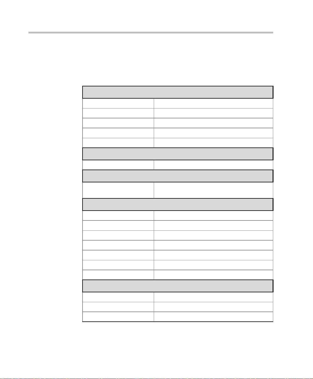
MGC-25 Specifications
Table 1-1 lists the specifications of the MGC-25 unit.
Table 1-1: MGC-25 Unit Specifications
Physical
Height 2U (88.90 mm)
Width 19” (48 cm)
Depth 19” (48 cm)
Weight Up to 31 lb (14 kg)
Free space ab ove MCU not required
Power Supply
AC Input 100–240 VAC, 50/60 Hz
Power Consumption
AC Maximum Power
consumption
Environment
Operating temperature 10°–40°C (50°–104°F)
Storage tem pera ture -40°–70°C (40°–158°F)
Relative humidity 15%-90% no condensing
Operating altitude Up to approx. 3,000 m (10,000 ft.)
Storage altitude Up to approx. 12,000 m (40,000 ft.)
Operating ESD +8 kV
Storage ESD +15kV
Diagnostics
Power up Yes
On-line Yes
Remote Yes
AC Voltage–up to 2 AMP at 100 VAC, 1 AMP at
240 V A C
1-4
Page 13
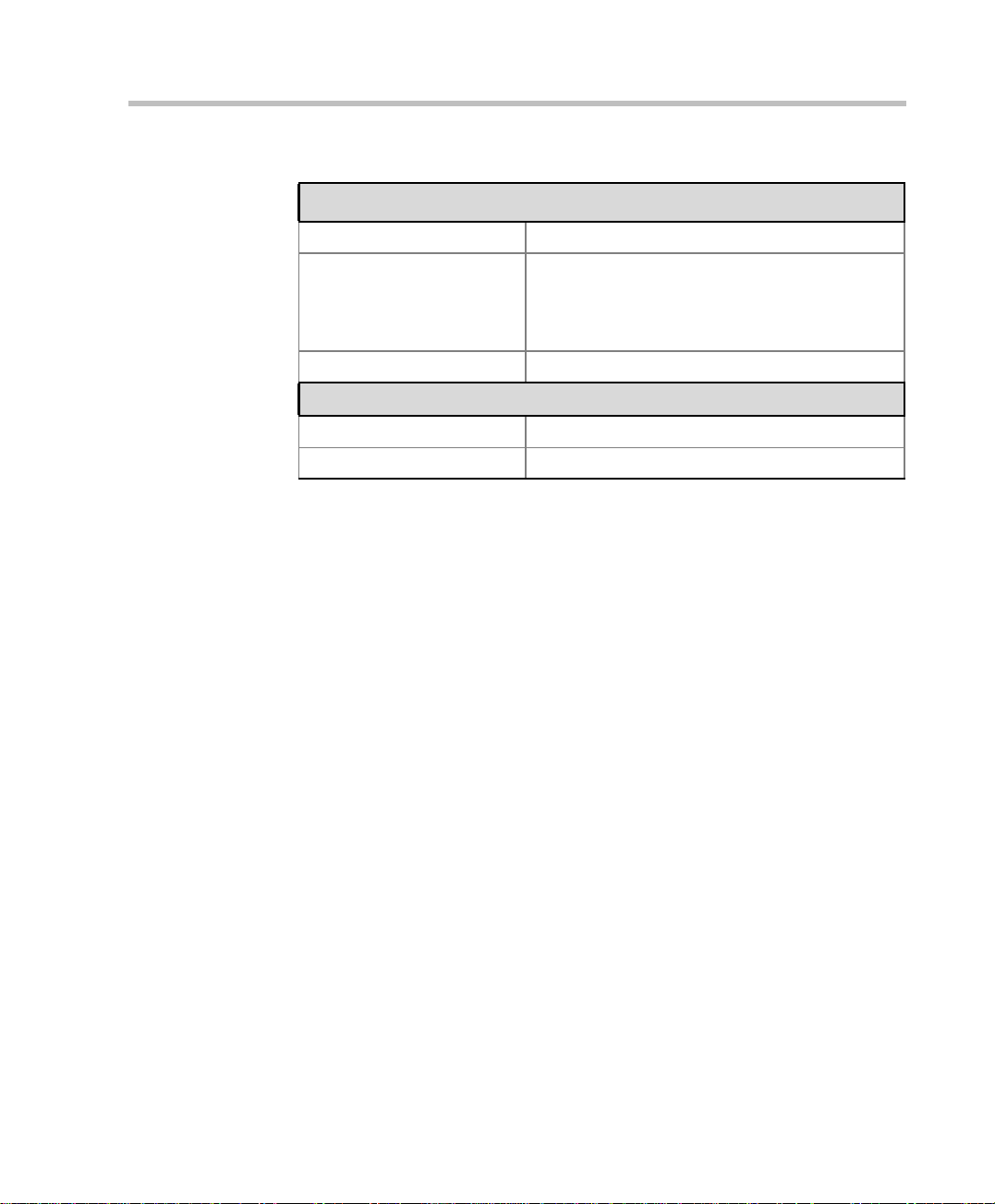
Chapter 1 - Before You Begin
Table 1-1: MGC-25 Unit Specifications
External Communications
Data rates 6 Kbps–1920 Kbps (E1)
Network interfaces ISDN: T1 PRI, E1 PRI, Multirate ISDN (H0),
NFAS, Leased Lines: T1/E1
T1-CAS lines
H.323 & SIP: LAN
Clock synchronization Synchronizes to external netw ork
Local/Remote external equipment
Operator workstations LAN/RS-232/Modem/Internet
Reservation systems LAN/Internet/Modem
1-5
Page 14

MGC-25 Getting Started Guide
Overview of this Getting Started Guide
The MGC-25 Getting Started Guide includes the following topics:
Chapter 1 - Before You Begin
This chapter includes th e following:
• System Overview
• Safety Requirements
• General Site Requirements
• System Specifications
• Getting Started Guide Overview
Chapter 2 - Hardware Description and Installation
This chapter includes th e following:
• Descriptions of the front panel, back panel, dongle and LCD display
window
• Instructions for installing the MGC-25
Chapter 3 - Software Installation and Configuration
This chapter includes instructions on how to:
• Configuring the initial IP configuration of the system
• Installing the MGC Manager
• Starting the MGC Manager
• Defining an MCU
• Conecting to an MCU
• Configuring the network services
1-6
Chapter 4 - Conference Types
This chapter describes the major types of conferences that can be scheduled
on the MGC-25, such as: on-demand conferences, scheduled conferences,
video conferences, Audio Only conferences and Entry Queues.
Chapter 5 - Basic Operation
This chapter includes instructions on how to:
• Start a conference from the default conference templates
• Dialing in to a conference
Page 15

Chapter 1 - Before You Begin
• Monitor On Going Conferences
• Perform basic operations during an On Going Conference
Chapter 6 - Defining a New Audio Conference
This chapter includes instructions on how to:
• Define the basic parameters of a new Audio Only Entry Queue
• Define a new Audio Only conference
• Define an Audio Only Meeting Room
Chapter 7 - Defining a New Video Conference
This chapter includes instructions on how to:
• Define the basic parameters of a new Video Entry Queue
• Define the basic parameters of a new Video Conference
• Define a new Video Meeting Room
Chapter 8 - MGC-25 Management Tools
This chapter describes the management tools unique to the MGC-25:
• Resource Report
• MCU System Configuration
• MGC-25 Cards Management
• Resetting the MCU
• MCU Faults Report
Appendix A - Default Templates
This appendix describes the default conference templates that are installed
with the MGC Manag er.
1-7
Page 16

MGC-25 Getting Started Guide
1-8
Page 17
Hardware Description and Installation
Be sure to follow the safety precautions on page 1-2 before installing your
system.
Hardware Description
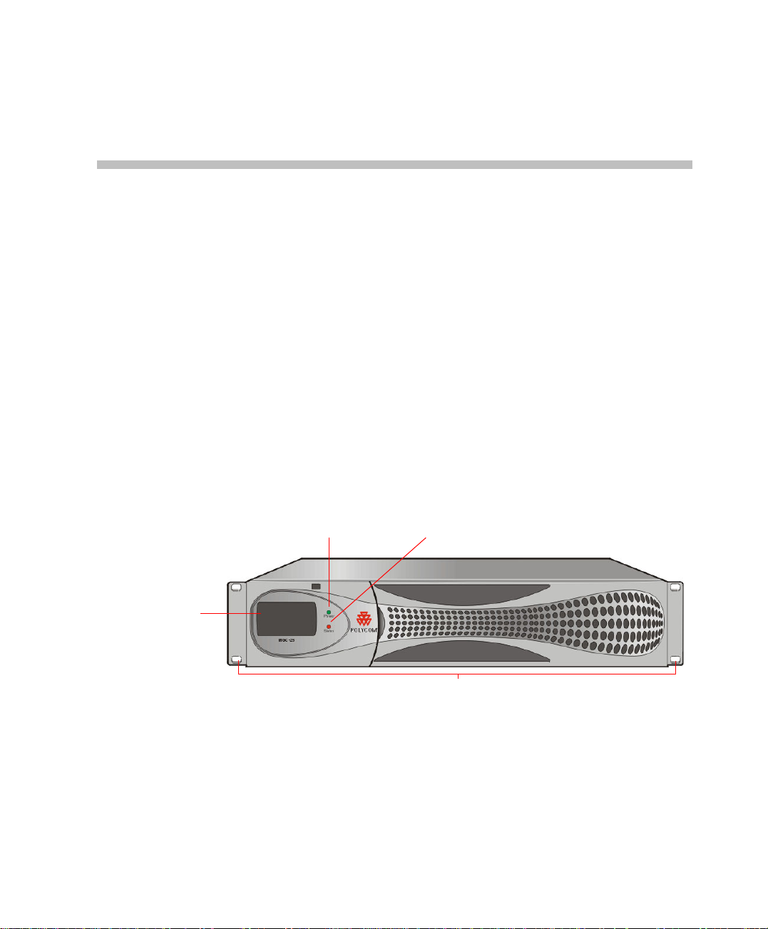
Front Panel
The MGC-25 front panel in clu des an LCD Display window which indicat es
system and network statuses.
2
LCD Display
Window
Power LED indicator
Status LED indicator
Front brackets
2-1
Page 18
MGC-25 Getting Started Guide
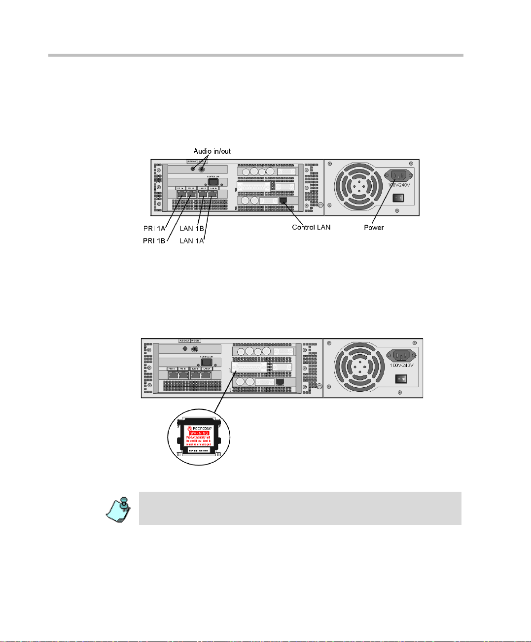
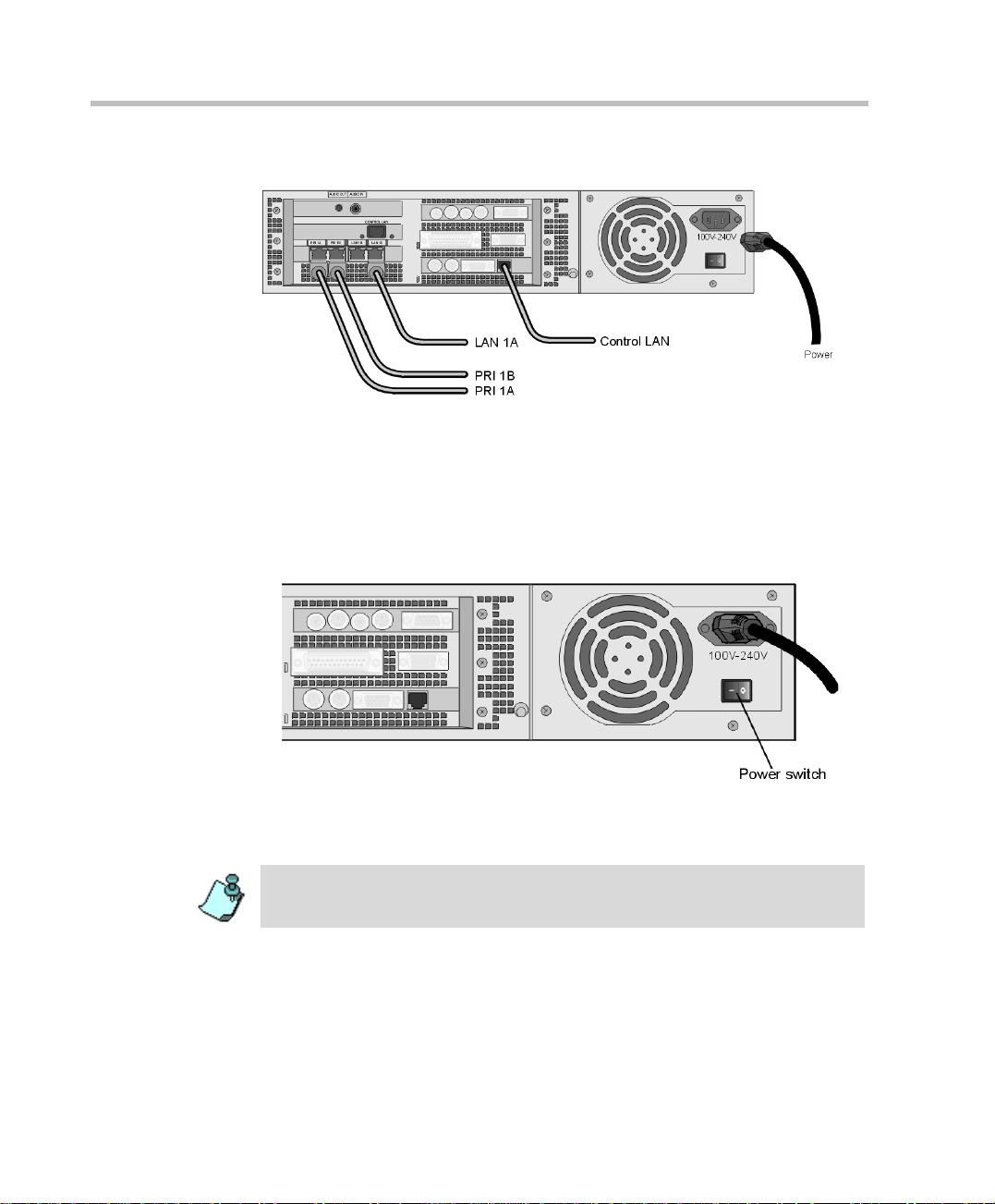
Rear Panel
The MGC-25 rear panel includes interfaces for two PRI connections, two
LAN connections, one Control LAN connection, a power cable, power
switch, cooling fan and interfaces for Polycom Support personnel.
Dongle
The Polycom MGC-25 Dongle is a hardware key that is installed in the
parallel port on the rear panel. This device contains configuration and
licensing data that is necessary for your system to function.
2-2
Never remove the dongle unless instructed by authorized support personnel.
Do not remove or damage the dongle label.
Page 19
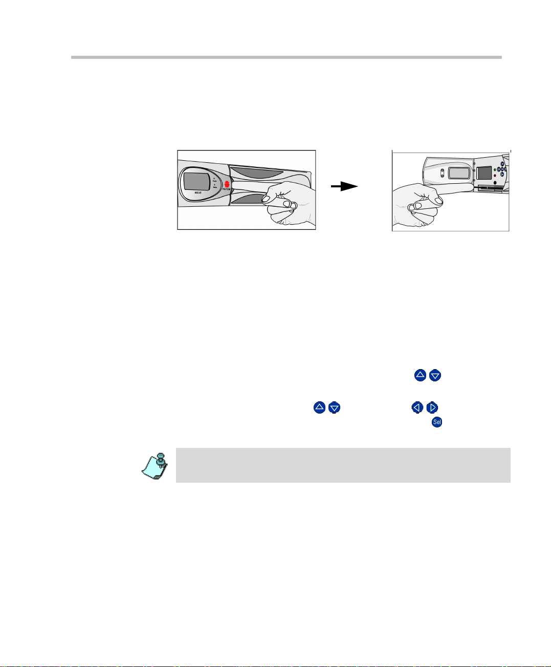
MGC-25 LCD Display Window
Open the panel door to access buttons for scrolling through the LCD screens
and configuring the system.
Working With the LCD Display Window
The LCD display window enables you to configure the MCU IP address and
view system status information without connecting to any external device.
The first time you use the MGC-25, the IP Configuration screen is displayed.
To navigate within an LCD Display:
Using the arrow buttons next to the LCD display window, you can navigate
within an LCD display to choose options, view system status, modify the
MCU IP address, save data and cancel parameter modifications.
Chapter 2 - Hardware Description and Installation
• To scroll vertically in a display, use the up/down ( / ) buttons.
• On some displays, OK and Cancel o ptions ap pear. To select one o f these
options, use the up/down ( /) and left/right ( / ) buttons to
highlight the desired option and then press the Select ( ) button to
execute the operation.
When modif y ing the parameters on the IP Configuration disp lay, navigation
works differently.
2-3
Page 20
MGC-25 Getting Started Guide
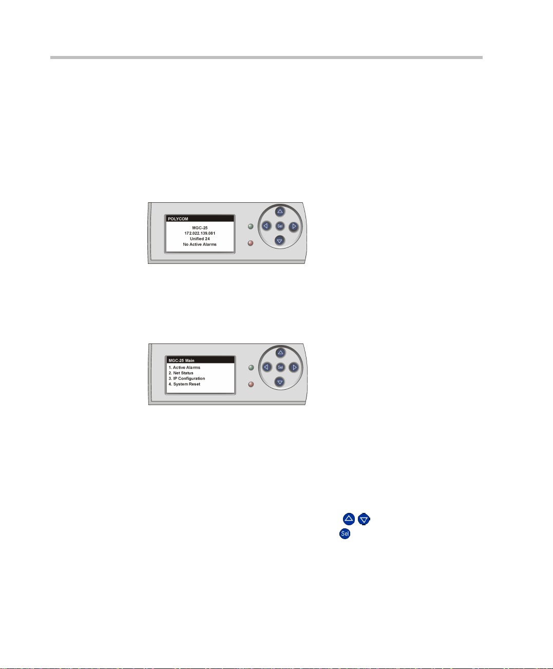
System Idle Display
When there are no actions being performed via the LCD Displ ay or no alarms
detected, the following info rmation is displayed:
• Product Name
• IP Address
• Configuration Name
• Active Alarms Status
This display is shown whenever there have not been any actions performed
via the LCD Display for 30 seconds.
Main Menu
To access the Main Menu from the System Idle display, press any button.
2-4
The Main Menu in the LCD window includes four options:
• Active Alarms - displays network and system errors, if any
• Net Status - displays the status of each network connection
• IP Configuration - displays the IP address, Subnet Mask and Default
Gateway addresses. You can configure these values.
• System Reset - resets the system
T o access an option, scroll with the up/down ( / ) buttons until the desired
option is selected, and then press the Select ( ) button.
Page 21
Chapter 2 - Hardware Description and Installation
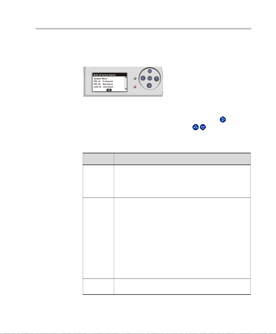
Active Alarms
To access the Active Alarms, select the first option from the MGC-25 Main
menu.
If there are no active alarms, selecting the Active Alarms option shows the
System Idle display.
To scroll vertically thro ugh the Active Alarms, press the right ( ) bu tton to
highlight the scroll bar and then use the up/down ( / ) buttons to scroll.
The possible alarms are described in Table 2-1:
Table 2-1: Alarms Shown in the LCD Display Window
Alarm Ty pe Description
System
Errors
PRI Errors R - Red Alarm
LAN Errors L - Link Down - There is no signal from the network.
Major/Minor Alarm
The system has an error. To view details about the error: in the
MGC Manager, right-click the MCU icon, and then click Faults.
For details about Faults, see the MGC Administrator’s Guide,
Chapter 5.
No connection is detected . T here are no ph ysic al or h igher l ayer
protocols estab lis hed. The line cannot be us ed for s erv ic e whe n
a red alarm is detected. Check the network cable.
Y - Yellow Alarm
The system is receiving a “Far End Alarm Failure.” This failure
indicates that layer 1 and layer 2 protocols have been
established but the layer 3 protocol is not yet established. The
line cannot be used for service when a yellow alarm is detected.
Check the network cable and contact your service provider.
N - Normal
D - D Channel not established.
Check the network cable and contact your service provider.
N - Normal
2-5
Page 22
MGC-25 Getting Started Guide
Table 2-1: Alarms Shown in the LCD Display Window
Alarm Type Description
Control
LAN errors
L - Link Down - There is no signal from the network.
N - Normal
T o retu rn to th e Main Me nu, use the left/right ( / ) buttons to highlight th e
OK option, and then press the Select ( ) button.
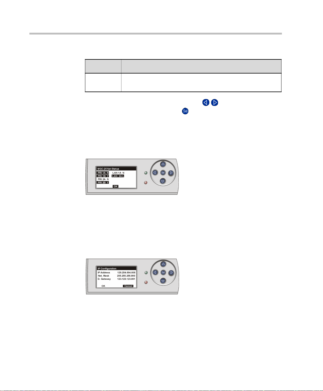
Net Status
The Net Status display lists all network links with their available statuses.
If there are no active alarms, selecting the Net Status option shows the System
Idle display.
Network statuses are described in Table 2-1.
IP Configuration
The IP Configuratio n function is available in the Main Menu and is displayed
automatically the first time you access the system.
The IP Configuration di splay shows t he IP add ress, Subnet Mask a nd Default
Gateway values of the system.
2-6
To modify these values, follow the instructions on page 3-1.
Page 23
Chapter 2 - Hardware Description and Installation
To save the values and reset the system, use the left/right ( / ) buttons to
select OK, and then press the Select ( ) button.
Alternatively, to return to the Main Menu without saving changes, use the
left/right ( / ) buttons to select Cancel, and then press the Select ()
button.
The OK option appears only if a component has been modified.
When the cursor is on the first component of the IP address, you can press the
left arrow button to access the OK and Cancel options.
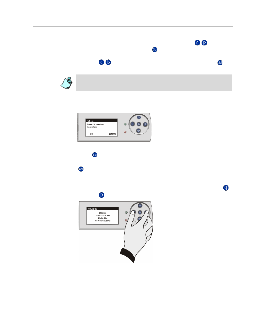
System Reset
The System Reset function is available from the Main Menu.
To reset the system, use the arrow buttons to select OK, and then press the
Select ( ) button.
To cancel, use the arrow buttons to select Cancel, and then press the Select
( ) button.
Manual System Reset
You can reset the system manually at any time by holding down the left ()
and right ( ) buttons sim ultaneously.
2-7
Page 24
MGC-25 Getting Started Guide
Hardware Installation
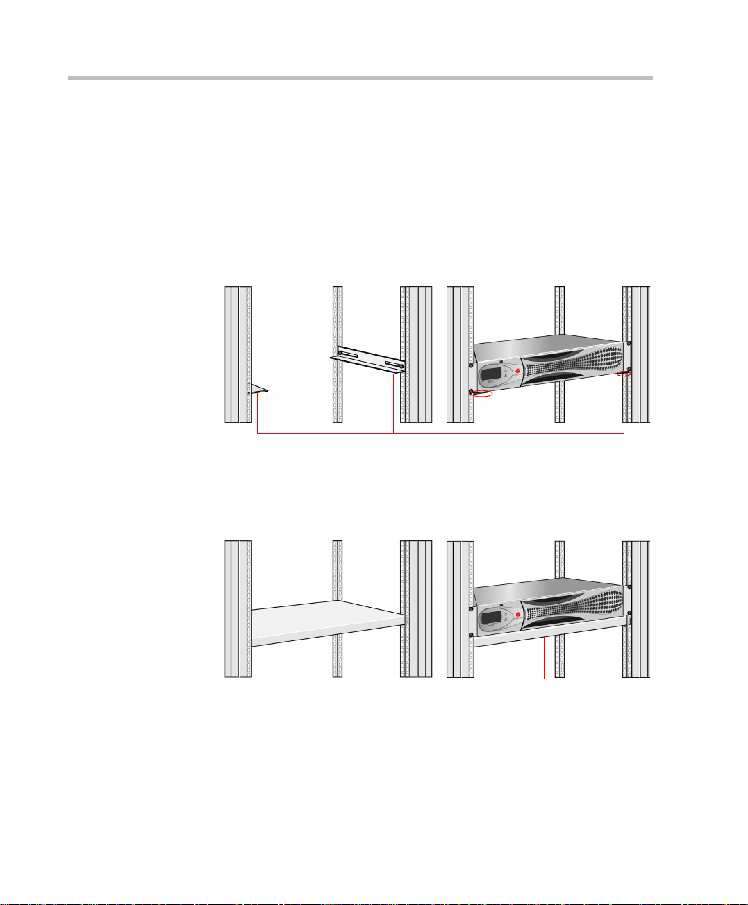
Installing the MGC-25 in a Rack
There are two methods to install the system in a rack:
• Install brackets supplied by the rack manufacturer on each side of the
rack on which the MGC-25 is placed. Secure the system by fastening
four screws to the rack on the front panel.
Place the system on brackets that have been installed
according to rack manufacturer specifications
2-8
• Install a shelf supplied by the rack manufacturer. Place the MGC-25 on
top of the shelf. Secure the system by fastening four screws to the rack
on the front panel.
Place the system on a shelf that has been installed
according to rack manufacturer specifications
Page 25
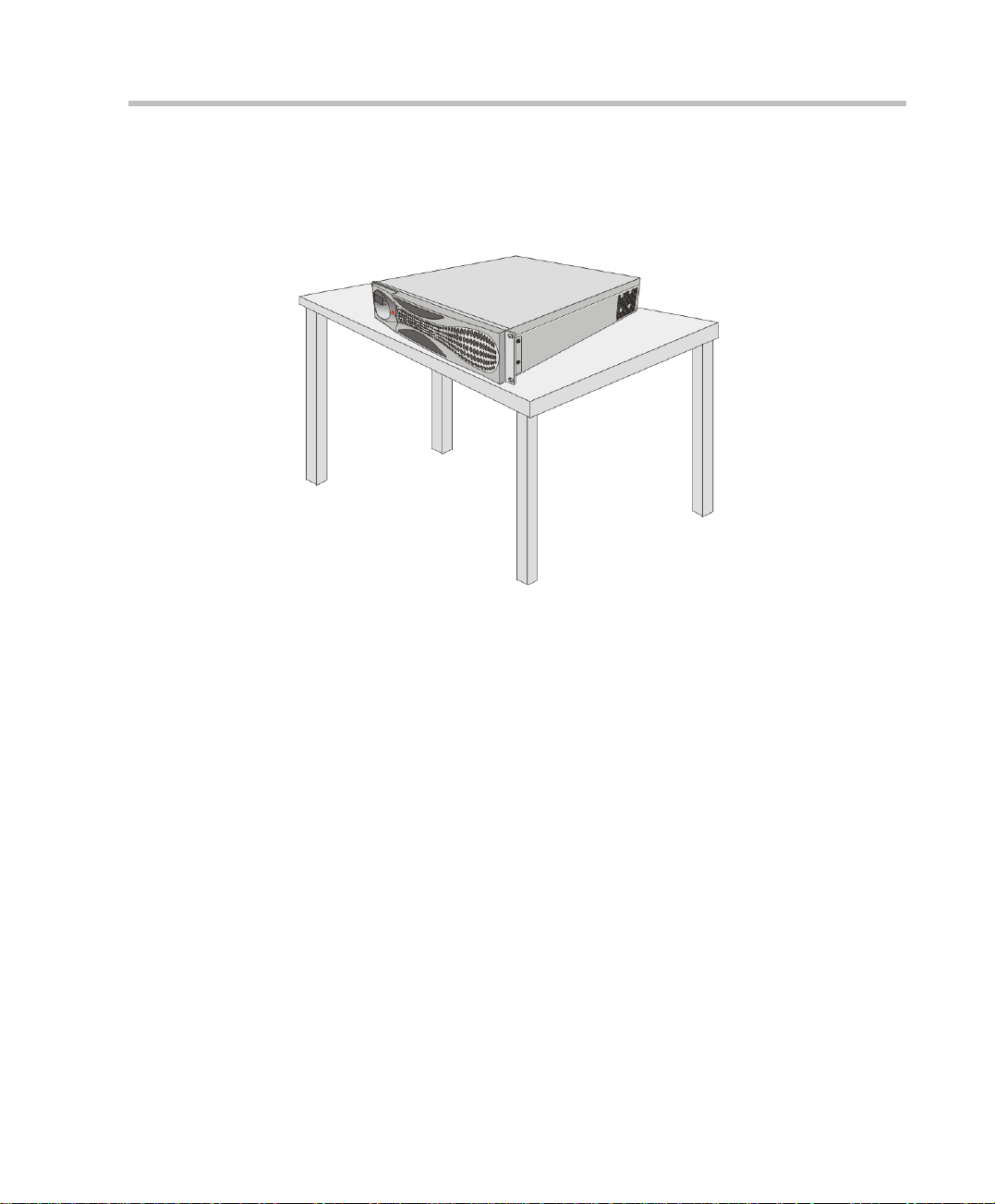
Placing the MGC-25 on a Desktop
Place the system on a secure, flat and clean surface and avoid placing
anything on top of the system.
Chapter 2 - Hardware Description and Installation
Connecting Cables
Connect the following cables:
• Power cable - insert the connector firmly into the socket so that almost
all of the narrow section of the connector is inserted
• ISDN PRI or T1-CAS cables (optional)
• LAN network cable (optional)
2-9
Page 26
MGC-25 Getting Started Guide
• Control LAN cable (to the LAN network with MGC Manager PC)
Powering Up the System
1. Make sure the power cable is connected to the system and to a grounded
power outlet.
2. Press the power switch to “1” to start the system.
2-10
On the front panel of the MGC-25 the power indicator LED and the LCD
Display Window flash. The system startup may take upto five minutes.
Wait at le ast 10 secon ds bet ween turning the sy stem of f and turning it on. I f yo u
turn the system o f f an d then try to turn it on rig ht aw ay, the system will not allo w
powering up for one minute.
Page 27
Initial System Setup
3
Initial IP
Configuration
Installing the
MGC Manager
Start ing the MGC
Manager
Defining an MCU
Connecting
to an MCU
Configuring the
Network Services
The MGC-25 requires basic configuration before you can start running
conferences.
Initial IP Configuration
The system is shipped with a default IP address: 129.254.4.8. Whenever the
system is turned on, the system checks the IP address. If the currently
defined IP address is 129.254.4.8, the system assumes that it has not been
configured and shows the IP Conf igurat ion paramet ers o n the LCD windo w.
You can now enter the IP address allocated to the MCU using the LCD and
the arrow keys.
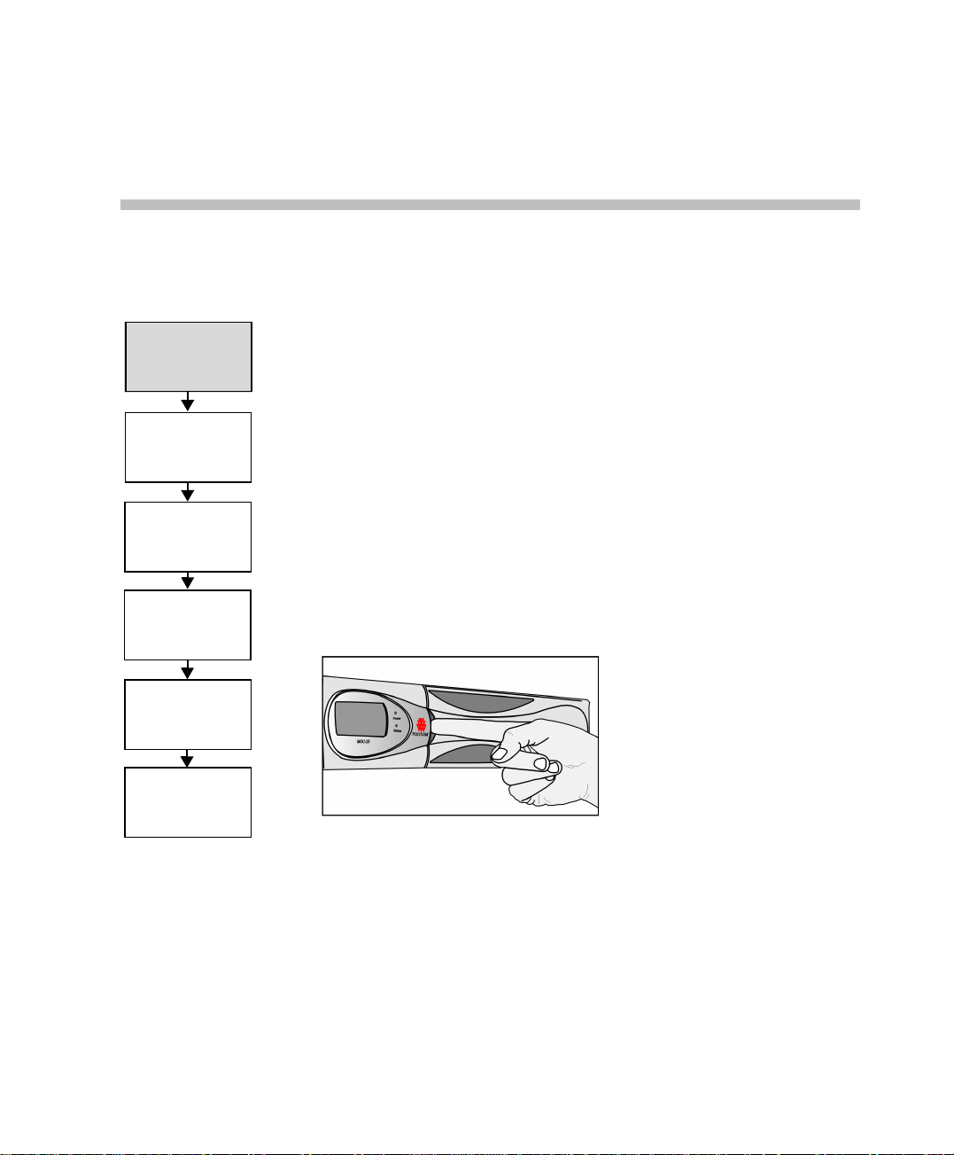
To configure the IP address of the MGC-25:
1. Open the panel for the LCD as shown:
The IP Configuration is displayed.
3-1
Page 28
MGC-25 Getting Started Guide
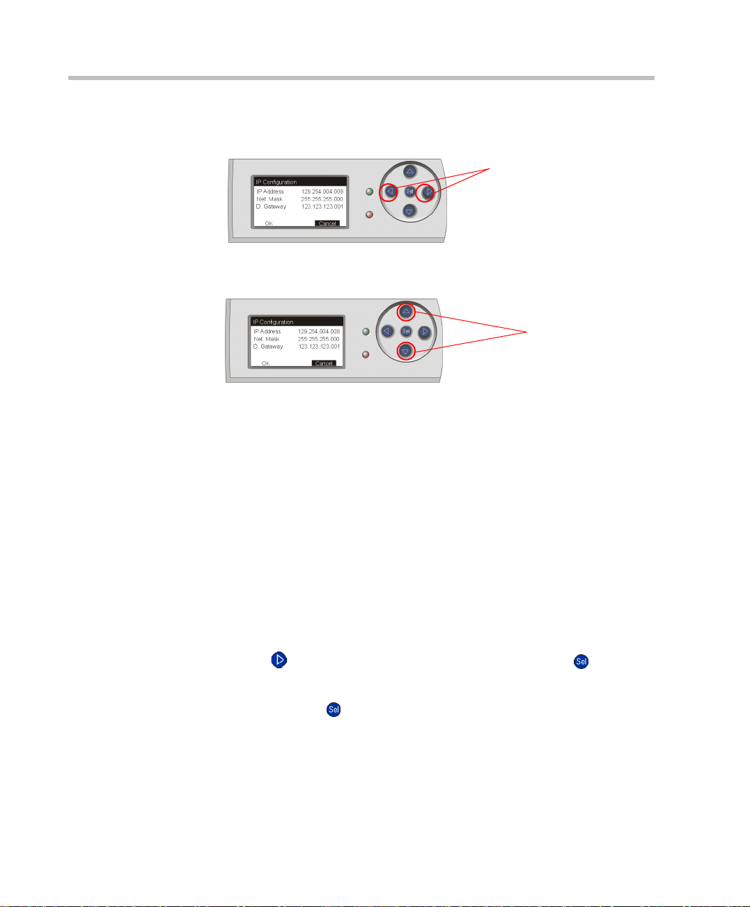
2. Start by modifying the IP Address.
3. Using the up/down buttons, modify the number. The number value range
4. After modifying a component, press the Right arrow button to move to
5. Repeat steps 2 to 4 to modify the remaining components of the IP
Using the Left/Right buttons, move to the desired number to modify.
Left/Right Buttons
is 0-255. To scroll through the numbers by tens, keep the button pressed.
Up/Down Buttons
the next component to modify. Press the Left arrow button to return to a
previous component.
address.
3-2
6. Press the Right arrow button to move to the Subn et Mask IP number. The
Subnet Mask is assigned values according to the IP address entered.
If you do not want to modify the Subnet Mask, press the Right arrow
button until you reach the Default Gateway number. If no additional
changes are required, skip to step 8.
7. Enter the IP address of the Default Gat eway if the MCU is conne cted t o a
network other than the one used by the PC running the MGC Manager.
8. After completing the modifications of all numbers, press the Right arrow
button ( ) until OK is selected, and then press the Select ( ) button.
A notification that the system will be reset is displayed.
9. Press the Select ( ) button to reset the system.
Page 29
Installing the MGC Manager
To set up conferences and to control the MGC unit you must install the MGC
Initial IP
Configuration
Manager software on a PC. Up to 30 MGC Manager-enabled PCs can be
connected to each MGC-25. A single MGC Manager-enabled PC can manage
multiple MGC systems.
Chapter 3 - Initial System Setup
Installing the
MGC Manager
Start ing the MGC
Manager
Defining an MCU
Connecting
to an MCU
Configuring the
Network Services
During the installa tion, default Reservation templa tes are installed.
The MGC-25 is shipped with a default IVR Service, default Entry
Queue Service, and a default conference profile. For information
about restoring these services when upgrading MCU software, refer
to the MGC Administrator’s Guide, Chapter 5.
To install the MGC Manager software:
1. Insert the software CD into the CD drive.
2. On the Start menu, click Run.
The Run dialog box opens.
3. Type D:\SETUP (where D is the name of the CD drive), and then click
OK.
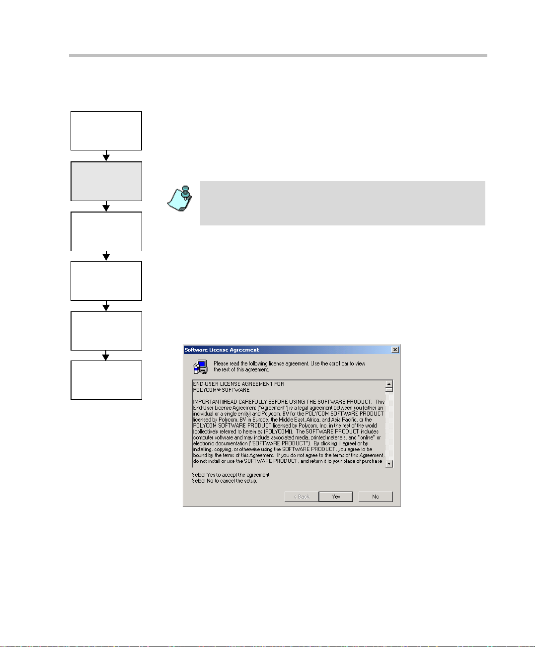
The installation wizard starts a nd the License Agreement window opens.
3-3
Page 30
MGC-25 Getting Started Guide
4. Click Yes to agree to the terms of the agreement or No to exit the
5. Click Next.
installation.
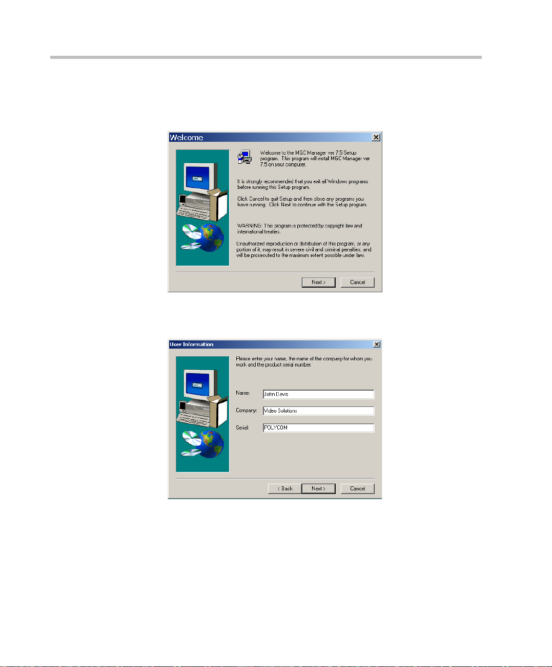
If you clicked Yes, the Welcome window opens.
The User Information screen opens.
3-4
6. Enter your name and the name of your company in the appropriate
boxes.
For a standard installation, enter Polycom in the Serial box.
7. Click Next.
Follow the on-screen instructions to complete the installation process.
Page 31

Chapter 3 - Initial System Setup
At the end of the installation procedure, the Setup Complete window
opens.
8. Click Finish.
The MGC Manager software is now installed on your computer.
3-5
Page 32

MGC-25 Getting Started Guide
Starting the MGC Manager
Initial IP
Configuration
Installing the
MGC Manager
Start ing the MGC
Manager
Defining an MCU
Connecting
to an MCU
Configuring the
Network Services
The MGC Manager can connect to several MGC units simultaneously. The
first time you run the MGC Manager application, or when a new MCU is
added to your conf iguratio n, you must first def ine each MCU’ s I P address an d
listening port number.
The MGC unit has to be inst alled and it s IP address properly co nfigured
before defining its connection parameters in the MGC Manager
application. For details, see “Initi al IP Co nfigura tion ” on p age3-1 in this
guide.
To define an MGC c onnection:
• On the Start - Progra ms menu, click MGC Manager ver 7.5, and then
click MGC Manager ver 7.5 to start the application.
The MGC Manager main window opens.
Main Menu
Toolbars
3-6
Status pane
Browser
pane
Monitor pane
Page 33

Defining an MCU
To define a new MCU:
Initial IP
Configuration
1. In the Browser pane, right-click the MCU Network icon, and then click
New MCU.
Chapter 3 - Initial System Setup
Installing the
MGC Manager
Starti ng the MGC
Manager
Defining an MCU
Connecting
to an MCU
Configuring the
Network Services
The Add MCU dialog box opens.
2. In the Name box, enter the name of the MCU. Specify a n ame that clearly
identifies the MCU.
3. In the IP Address box, enter the IP Address of the MCU.
The IP address should be identical to the one configured in the LCD
Display during the Initial IP Configuration settings.
4. Click OK.
The Add MCU dialog box closes. A new icon with the specified MCU
name appears in the Browser pane listed below the MCUs Network icon.
3-7
Page 34

MGC-25 Getting Started Guide
Connecting to an MCU
Initial IP
Configuration
Installing the
MGC Manager
Start ing the MGC
Manager
Defining an MCU
Connecting
to an MCU
Configuring the
Network Services
Once the MCU connection parameters are defined, the MGC Manager can be
connected to all defined MCUs simultaneously. The MGC Manager allows
you to set up conferences, make reservatio ns, monitor On Going Co nferences
and perform other activ ities on se veral MCUs. Th e MGC Manager repo rts the
status of each MCU connection.
To connect the operator workstation to an MCU:
1. In the Browser pane, doubl e-click the MC Us Network icon, or expand the
MCUs Network icon.
A list of MCUs appears below the MCUs Network icon.
2. Double-click the MCU icon.
Alternatively, right-click the MCU icon to which you want to connect ,
and then click Connect.
The Logon dialog box opens.
3-8
3. Enter your Login Name and Password, and then click OK.
Each MCU is initially configured with a default operator whose Login and
Password are both POLYCOM. Additional operators can be defined. For more
details, see the MGC Administrator’s Guide, Chapter 6.
Page 35

Configuring the Network Services
Chapter 3 - Initial System Setup
Initial IP
Configuration
Installing the
MGC Manager
Starti ng the MGC
Manager
Defining an MCU
Connecting
to an MCU
Configuring the
Network Services
If no Network Services have been configured, depending on your system
configuration, an appropriate Network Configuration dialog box is
automatically displayed.
• If your system is co nfigured to work wit h both IP and ISDN, the Network
Configuration Wizard di alog box is displayed. This secti on d escrib es t he
configuration of both IP and ISDN Network Services.
• If your system is configur ed to work with IP only, the IP Configuration
dialog box is displayed. For details, see page 3-10.
• If your system is configured to work with ISDN only, the ISDN
Configuration dialog box is displayed. For details, see “To configure an
ISDN Network Service:” on page3-14.
Network Configuration Wizard
The Network Config uration Wizard enables you to set up the ISDN and IP
network services quickly.
For information about defining T1-CAS Network Services, defining
additional ISDN or IP Netw ork Servic es, ad ding advan ced d efiniti ons o r
modifying existing Network Services, refer to the MGC Administrator’s
Guide, chapter 3.
You can access the Network Configuration Wizard any time from the MCU
right-click menu.
3-9
Page 36

MGC-25 Getting Started Guide
You can start the configuration process in any order, by clicking the
appropriate Network button.
To route Meet Me H.323 dial-in participants to their conferences, some
gatekeepers require configuration of an IP Network Service prefix. If your
gatekeeper requires the definition of a prefix, configure it in the gatekeeper
before you define the IP Network Service.
To configure the IP Network Service:
1. In the Network Configuration Wizard window, click the IP button.
The IP Configuratio n dialog box opens.
3-10
Page 37

2. Define the following parameters:
Table 3-1: IP Configuration Parameters
Field Description
Chapter 3 - Initial System Setup
IP Service
Name
Obtain IP
Address
Automatically
(DHCP)
LAN 1A
Spans
Configuration
LAN 1 IP
Address
Subnet Mask Enter the subnet mask of the MCU’s IP card. If the
Enter a name using up to 20 characters, or use the
default name (IP Default Service).
Select this check box to use a DHCP server for
automatic assignment and tracking of IP addresses to
the conference devices.
Do not select this check box if you need to establish a
static IP address, for example, when working with a
firewall and you need to translate an internal IP add ress,
that must be static, with an external one.
Select this check box to indicate that a LAN span is
connected to the IP card in the MCU and to define the
properties of this card.
Enter the IP address of the IP card instal led in the MCU.
When the DHCP server is used, the IP address of the
card appears as 0.0.0.0.
DHCP is used, the subnet mask is automatically
retrieved from the DHCP server and cannot be
modified. For more d etails, see the MG C Administra tor’s
Guide, Chapter 3, “Defining an IP Network Service”.
The detected number appears in the card’s
Properties-Settings-IP Network Parameters box. For
more details, see the MGC Administrator’s Guide,
Chapter 4, “Viewing the IP Card Properties”.
Default Router Enter the IP of the default router in this box. If a DHCP is
used, the IP address of the default router is
automatically retrieved from the DHCP server and
cannot be modified.
3-11
Page 38

MGC-25 Getting Started Guide
Table 3-1: IP Configuration Parameters (Continued)
Field Description
DNS DNS — Select this check box to indicate that a DNS
server is used in the network and then select:
• Specify — to enter the IP address of the DNS
server.
• Auto — to automatically detect the primary DNS IP
address, provided the DNS Server is defined in the
DHCP and if the DHCP -obtain IP Address
Automatically check box was selected.
DNS Server IP
Address
Local Domain
Name
H.323 Select this option for an H.323-only network service or
Gatekeeper A gatekeeper is used witht he network, so select the
Gatekeeper IP
Address or
Name
LAN 1 H323 ID The H.323 identification is a nu mber us ed to i dentify the
Prefix Enter a number to be used as prefix when H.323
If DNS – Specify was selected, this field is mandatory.
Enter the IP address of the primary DNS server to be
used for name translation.
Enter the domain name where the MCU is installed.
The name of the domain includes the host part of URL
or URI, for example, polycom.com.
This field is used both for SIP proxy registration and
DNS resolution and therefore it is required if you are
using DNS servers in this service.
an integrated IP service.
Gatekeeper check box to define its properties.
Enter either the gatekeeper’s host name (if the DNS
server is enabled and the gatekeeper is registered with
the DNS), or IP address.
card’s span. It can be any whole number between 0 to
65535. This number is as signed to a s pecific IP address
and must be unique per MCU.
participants dial-in to the MCU. When PathNavigator is
used, this number automatically registers with the
gatekeeper. When another gatekeeper is used, the
prefix usually must b e re gis tere d i n th e g ate ke epe r first.
This number is used as part of the dial-in string given to
participants.
3-12
Page 39

Chapter 3 - Initial System Setup
Table 3-1: IP Configuration Parameters (Continued)
Field Description
SIP Select this check box to indicate that SIP participants
can connect to the MCU using this service. Then select:
Specify—to manually define the SIP server.
Auto— to automatically detect the SIP server’s IP
address if a DHCP or if a DNS Server is present and
defined.
SIP Server IP
Address or
Name
Domain Name
or IP Address
If SIP – Specify was selected, enter either the IP
address of the preferred SIP server or its host nam e (if a
DNS server is used)
Conferences and En try Q ueues can be regist ered i n the
proxy in the format user@host. for example,
EQ1@polycom.com.
When dialing to a conference or Entry Queue, the SIP
server expects to receive the host either as domain
name or as an IP address.
The domain name is used for identifying the SIP server
in the appropriate domain according to the host part in
the dialed string. For example, when the call to
EQ1@polycom.com reaches its th e outbound proxy, this
proxy looks for the SIP server in the polycom.com
domain to which it will forward the call.
When this call arriv es to the SIP ser ver in poly com.c om,
the server looks for the registered user (EQ1) and
forwards the call to this Entry Queue or conference.
3. Click OK.
If your system supports only IP networks, a confirmation message is
displayed.
3-13
Page 40

MGC-25 Getting Started Guide
4. Click OK to confirm.
If you are defining only the IP Network Service, the Network Configuration
dialog box closes and the new IP Network Service appears in the IP Network
Services list. You must reset the MCU.
To configure an ISDN Network Service:
1. Click the ISDN button.
If you are defining both IP and ISDN Network Services, the Network
Configuration Wizard dialog box is displayed.
3-14
Page 41

The ISDN Configuration dialog box opens.
2
Chapter 3 - Initial System Setup
3
5
6
7
4
2. In the ISDN Service Name box, enter a name or use the default name
(ISDN Default Service).
3. Select the PRI 1A check box to define the parameters of the first ISDN
span.
4. If a second span is connected to the MCU, select the PRI 1B check box.
5. From the Line Type drop-down list; select either T1 (usually in the U.S),
or E1 (usually in Europe).
6. From the Switch Type drop-down list, select the brand and revision level
of equipment installed in the telephone company’s central office.
7. In the Dial-In Numbers Range boxes, enter the pho ne numbers to be used
for dial-in connection s as allocated to th e MCU by your service pr ovider.
Enter the first and last numbers in the range of phone numbers.
8. Click OK.
A confirmation message is displayed.
9. Click OK.
The Network Configuration dialog box closes and the new Network
3-15
Page 42

MGC-25 Getting Started Guide
Services appear in the Network Services list. These Network Services
automatically set as the default services.
The following icons are used to indicate the IP Network Service type:
Table 3-2: IP Network Service Icons
Icon Description
The Network Service supports both SIP and H.323
connections.
3-16
The Network Service supports only H.323
connections.
The Network Service s up ports only SIP connections.
The Network Services definition is complete.
For advanced settings, see the MGC Administrator’s Guide, Chapter 3.
Page 43

Modifying Network Services
T o make changes in t he IP and IS DN configurat ions, right -click th e MCU and
select Fast Configuration Wizard. The Network Configuration Wizard
window opens.
To change IP configurations click the IP button. To change ISDN
configurations click the ISDN button. For information regarding the
configurable fields in the relevant dialog boxes see “Network Configuration
Wizard” on page 3-9. For additional information abut setting the Network
Service as default, see the MGC Administrator's Guide, Chapter 3, “Setting
the Default Network Service”.
Chapter 3 - Initial System Setup
3-17
Page 44

MGC-25 Getting Started Guide
3-18
Page 45

Conference Types
This chapter gives an overview of basic conference types. For a full
description of conference types, see the MGC Manager User’s Guide,
Volume I, Chapter 4.
On-demand Conferences (Reservationless Conferencing)
Reservationless conferencing enables you to immediately start and connect
to On Going conferences from your endpoint, with no advan ced scheduli ng.
The MGC Manager offers two methods for Reservation-less conferencing:
• Ad Hoc Conferencing
• Meeting Rooms
Ad Hoc Conferencing
4
In Ad Hoc conferencing, the participant connects to an Ad Hoc-enabled
Entry Queue. An Entry Queue is a special routing lobby to which one or
more dial-in numbers are assigned. The participant is prompted for the
destination conference Numeric ID. If no conference with a matching
Numeric ID is running, the system creates a new On Going conference,
provided the participant has the permission to do so. The new conference is
created according to the conference paramete rs defined in a Profi le assigned
to the Entry Queue. In this method, the conference Profile is created only
once, and is used repeatedly to create numerous conferences.
This conferencing mode is useful when you want to allow all employees in
your organization to start On Going Conferences from their endpoints
without having to define conference parameters for each emp loyee and each
conference.
4-1
Page 46

MGC-25 Getting Started Guide
If an external database authentication is configured for the Entry Queue and
the conference, the MCU verifies with the external database whether a
conference with that Numeric ID can be started.
For more information about Ad Hoc conferencing, see the MGC Manager
User’s Guide, Volume II, Chapter 3.
Meeting Rooms
Meeting Rooms are conferences created once, with no starting date or time,
that can be activated as many times as required. The Meeting Room remains
in passive mode until the first participant connects to it and activates the
conference. To start the conference you simply let the participants know the
start date and time, dial-in number and the Numeric ID of the conference. No
prior booking is required. The conference returns to passive mode once the
conference ends and remains in the MCU memory unti l the next activat ion. In
this mode you must define a Meeting Room for each of the employees i n your
organization. This may r equire tediou s work when your organi zation inclu des
many employees, and it also loads the MCU memory with all the saved
Meeting Rooms.
Scheduled Conferences
You can define a conference to start at a certain date and time or to sta rt
immediately. Scheduled conferences run once and are then deleted from the
MCU memory. For scheduled conferences, the MCU reserves resources for
the conference participants, provided the participant endpoints are defined
during the conference definition. You can define conferences without
defining their participants and let participants connect to the conference as
long as there are resources available.
4-2
Page 47

Video Conference Attributes
There are four general types of video conferences:
• Video Switching - A conference in which all participants u se the same
video and audio formats. Whenever a participant starts to speak, the
participant appears on all screens as the conference is a voice activated
video switching conference.
• Transcoding (requires Video card) - A conference in which participants
use different video, audio and data formats, while maintaining the
highest video and audio capability each participant can achieve with his
or her codec. Like video switching, the current speaker is displayed on
all terminals.
• Continuous Presence (requires Video card) - A conference in which
several participants can be viewed simultaneously. In this type of
conference, the highest video , audio and dat a qua lity for each partici pant
depends on the parti cipants endpoint capabilities.
In a traditional Continuous Presence conference, each participant uses a
different video port on the V ideo card. This method enabl es such features
as full Transcoding per participant, Personal Layouts (individualized
Continuous Presence layouts per par ticipan t) and main tenance of overall
video and audio quality for the conf erence—even when par ticip ants with
lower capabilities connect. However, this method limits the number of
Continuous Presence participants to the num ber of ports on the Video
card, which is six.
• Conference On Port (requires Video card) - A conferencing method
suitable for large Continuous Presence conferences or when several
Continuous Presence conferences are running on the MCU.
In Conference On Port, all conference participants use a single video
port. This method allows for more than six participants to join a
Continuous Presence conference and allows for up to six Continuous
Presence conferences to be run on the MCU.
In a Conference on Port conference, a video layout can be selected for
the conference, but all the participants, including the speaker, view the
same layout and the same participants. The Personal layout selection is
not available in Conference on Port and the video quality is determined
by the highest common video parameters and by the video line rate.
Chapter 4 - Conference Types
4-3
Page 48

MGC-25 Getting Started Guide
Entry Queue
Entry Queues are not conferences but a means for accessing conferences.
Therefore, when defining a conference, take into account the conference
access method you would like to apply.
An Entry Queue is a special routing lobby to which one or several dial-in
numbers are assigned. When callers dial this number, they access this Entry
Queue where they wait to be routed and connected to the conference. The
participants may be connected automatically to the conference if they have
used DTMF codes to provide the required conference password or numeric
ID (depending on the MCU configuration), or they wait for the operator’s
assistance (if enabled for the Entry Queue). Both Video and Audio Only
conferences an be accessed from an Entry Queue. For information about
defining an Entry Queue, see Chapter 6, “Defining a New Audio Only Entry
Queue” on page 6-1 or Chapter 7, “Defining a New Video Entry Queue” on
page 7-1.
4-4
Page 49

Basic Operation
This chapter describes how to start, monitor and manage On Going
Conferences.
Reservation Templates
A Reservation template includes the conference parameters, such as the
conference media (audio, video ), video session, line rate, v ideo p rotocol an d
other video parameters, IVR and more. The reservation can include the
conference participant parameters.
Default Reservation Templates
Five default Reservation templates are installed with the MGC Manager:
• Default-Audio: Audio Only with Default IVR service
• Default_COP: Conference On Port at 384 Kbps
• Default_Video: Continuous Presence Conference at 384 Kbps
• SW CP: Software Continuous Presence (H.323 only) at 384 Kbps
• Video-Switch: Video Switching at 384 Kbps
5
In order to run a Default_Video or Default_COP conference, the V id eo+ card
and MGC Version 5.6 or later must be installed in your system.
Using the default Reservation templates, you can schedule a conference to
start immediately (On Going Conference), or to start automatically at a
predefined date and time (Reservation). For details of the contents of the
default Reservation templates see “Appendix A: Default Templates”.
5-1
Page 50

MGC-25 Getting Started Guide
Starting a Confer ence
You can start an On Going Conference from one of the default Reservation
templates provided with the system, or you can define a new On Going
Conference. For more details about defining new conferences, see “Defining
a New Audio Conference” on page 6-1 or “Defining a New Video
Conference” on page 7-1.
To start an On Going Conference from a default Reservation template:
1. Connect to an MCU. For more details, see “Connecting to an MCU” on
page 3-8.
2. The Default folder in the Reservations Database window opens
automatically when you open the MGC Manager. Otherwise, access this
window by clicking Reservations in AccordDB from the Window
menu.
5-2
The Reservations Database window opens.
If the Reservations Database window did not appear automatically and is not
included in the Window menu options, reopen this window using the login
procedure described in the MGC Manager User’s Guide, Volume I, Chapter 3,
MGC Manager Basics.
3. Move the Reservations Database window by dragging the blue title bar.
You can also resize the window by clicking an edge and dragging it.
4. In the Reservations Database window, expand the Default folder to
display the list of default Reservation templates.
Page 51

Chapter 5 - Basic Operation
5. Right-click the icon of the appropriate Reservation template to start, and
then click Start Immediately. If more than one MCU is connected,
select the name of the MCU to run the conference from the pop-up list.
The conference begins and appears in the list of On Going Conferences.
If no participants were defined in the Reservation template, the
conference starts but contains no participants.
5-3
Page 52

MGC-25 Getting Started Guide
Dialing-in to a Conference
Dial-in participants can access the conference using the following methods:
• Audio Only and ISDN Video participants - dial the conference ISDN
dial-in number.
• H.323 participants when a gatekeeper is present - dial the IP Network
Service Prefix and conference Numeric ID or name.
• For conferences defined as Meet Me p er C onf eren ce or Meeting Rooms, th e
IP Network Service Prefix is displayed in the Status pane of the MGC
Manager.
• The IP Network Service prefix is assigned when defining the IP Network
Service. For more information about the IP Network Service, refer to
Chapter 3.
For example, if the IP Network Service prefix is 27, the conference
Numeric ID is 1478 and the conference name is ‘MARKETING’, the
participant can dial 271478 or 27MARKETING.
• H.323 participants when a gatekeeper is not present - dial the IP address
of the IP card.
• SIP participants (if the SIP server and domainare are defined in the IP
Network Service) - dial the conference URI. For example,
MRO1@polycom.com.
If the conference included IVR parameters, the participant will ha ve to enter a
password before entering the conference.
Dial-in participants can also access a conference via a single-dial Entry
Queue. The dialing methods are t he sa me as for t he con fere nce. In t he defau lt
templates, just the Audio On ly template is defined with Entry Queue Access.
To create a new video conference with Entry Queue Access, see “Creating an
On Going Video Conference” on page 7-6.
5-4
Page 53

Chapter 5 - Basic Operation
Viewing the Conference Dial-in Properties
The required numbers and passwords needed to enter a conference , in cludi ng
IP Network prefixes and Numeric IDs appear in the MGC Manager main
Status pane.
To view the list of On Going Conferences and their dial-in numbers:
• Expand the MCU icon, and then click the On Going Conferences icon.
The list of On Going Conferences with their Numeric IDs and dial-in
numbers are displayed in the S tatus pane.
In some cnfigurations, the ISDN/PSTN number is truncated by the PBX, and
you must add the appropriate prefix to the dial-in number that is displayed in
the Status pane.
Conference Access via Entry Queue
Using an Entry Queue minimizes the number of dial-in numbers that have to
be allocated to conferences and the number of conferences that require
registration with the SIP server and enables using one or a small number of
URI addresses for all dial-in connections.
All ISDN articipants di al the same Entry Queue dial-i n number, and once they
connect to the Entry Queue, are routed to their conference according to the
conference numeric ID or password that they enter.
H.323 participants dial the IP Network Service Prefix and the Entry Queue
Numeric ID. They are routed to the target conference according to the
conference numeric ID or password that they enter.
When a new conference reservation or Ent ry Que ue is defi ned the conference
or Entry Queue registers with the SIP prox y . The SIP participant registers.The
SIP participant uses the Entry Queue URI to access the Entry Queu e using the
format: Entry Queue name@domain name. For example,
EQ1@polycom.com.
5-5
Page 54

MGC-25 Getting Started Guide
Usually for SIP conferencin g, an Ad Hoc Entry Queue is used. In this
scenario, the first participant dials the Entry Queue and creates a new
conference, while the other conference participants dial directly to the
conference using the conference name or Numeric ID.
When dialing from a Microsoft Windows Messenger endpoint that does not
have DTMF capabilities, the first participant (who creates the new con ference
in Ad Hoc Conferencing) enters the Entry Queue name foll owed by the tar g et
conference name and the numeric ID in the format:
EQ Name (Target Conference Name)(Target Conference Numeric ID).
For example, EQ1(sales)(12345). In this example, the Entry Queue name is
EQ1, and a new On Going Conference by the name sales with the Numeric
ID 12345 will be created on the MCU.
You do not need to add the domain name to the conference name, as it is
automatically added by Microsoft Windows Messenger when the request is sent
to the SIP server.
Dial-out Participants
Dial-out participants, who are called by the conference, must be defined in the
system. For details, see “Adding a Participant to a Conference” on page 5-13.
5-6
For more information about how participants can access conferences, refer to
the MGC Manager User’s Guide, Volume I, Chapter 4.
Page 55

Monitoring On Going Conferences
You can monitor conferences and perform various operations while
conferences are running.
Monitoring involves viewing the status of On Going Conferences and the
status of their participants.
Three levels of monitoring are available with the MGC Manager:
• General Monitoring - You can monitor the general status of all the On
Going Conferences and their participants in the MGC M anager main
window.
• Conference Level Monitoring - You can view additional information
regarding the conference using the Conference - Properties option.
• Participant Level Moni toring - You can view detailed information on the
participant's status using the Participant - Properties option.
When an operator is available to attend participants, you can view the
status of participants in the Participants Queue window. For more
information about the Participants Queue, see the MGC Manager User’s
Guide, Vo lume I, Chapter 8.
Operations can be performed at the conference level or at the participant
level. For example, you can terminate a conference before its scheduled
ending or you can extend its duration. You can also disconnect an individual
participant while the conference is in progress, or temporarily mute
transmission to and from a site so that the other par ticipants c an hold a privat e
discussion. You can also connect dial-out participants during the conference
and add a new participant while the conference is in session.
Chapter 5 - Basic Operation
General Monitoring
Monitoring a conference enables you to keep track of its participants and its
progress. When monitoring a conference, you can check whether all its
participants are correctly connected and whether errors and faults have
occurred.
The MGC Manager allows you to monitor several On Going Conferences
simultaneously . The On Goi ng Conference information is easily avail able and
clearly represented.
5-7
Page 56

MGC-25 Getting Started Guide
Monitoring a Conference
When you click a conference icon, the conference appears in the Status pane.
However, to get more details regarding the conference and participants
statuses, it is advised to monitor the conferences through the Monitor pane in
the main window.
Automatic Monitoring of conferences is available. For details, see the MGC
Manager User’s Guide, Volume I, Chapter 5.
Displaying the conference and participants statuses in the Monitor pane:
1. Expand the MCU icon to displa y its options.
2. Double-click the On Going Conferences icon to list the On Going
3. Right-click the conference to monitor , and th en click Monitor to view all
Conferences.
the conference participants.
Alternatively, on the conference right-click menu, click Monitor Filter
to view only participants of the selected filtering category.
5-8
Page 57

Chapter 5 - Basic Operation
The Participant Monitoring Filter dialog box opens.
4. Select the appropriate check boxes that indicate the statuses to monitor.
The following statuses can be selected:
Table 5-1: Participant Statuses to be Monitored
Filtering Option Description
Faulty participant Participants who have problems connecting to the
conference.
Participants
Requesting
Assistance
Asked question Participants who want to ask questions and were
Noisy Line Participants wh os e li ne wa s d ete cte d b y th e M C U as
Participants who have requested the operator’s
assistance and have yet to be assisted by the
operator.
added to the Question-and-Answer queue. These
participants are waiting to as k a question.
noisy.
5-9
Page 58

MGC-25 Getting Started Guide
The conference details appear in the Monitor pane.
The Status and Monitor panes take the form of a table. Each row
represents a conference or a participant. Each column represents a status
item that is being mon itored. The Conference Name, Status, Phone#,
Connection Type, Retr ies Left, Channel# and Bonding fields also appear
in the Status pane.
5-10
You can modify the order of columns in the Monitor and Status panes by moving
the column heading(s) to the desired location in the table header.
The data in the Monitor and Status tables can be sorted according to a selected
column. Clicking on a column heading sorts the table data in descending order.
Clicking on the same column heading a second time sorts the data in ascending
order.
Additional information about monitoring parti ci pants and con ferences i s
described in the MGC Manager User’s Guide, Volume I, Chapter 5.
Listing Participants in the Browser and Status Panes
You can view the list of participants currently connected to the conference in
the Browser, Status and Monitor panes.
To view the list of participants in the
Browser pane:
1. Expand the On Going Conferences or Reservations tree to display the list
of On Going Conferences or Reservations.
Page 59

Chapter 5 - Basic Operation
2. Click the plus [+] icon next to the On Going Conference or Reservation
to list the participants.
The participants are listed below the conference or Reservation.
Different icons are used to indicate the participant roles and their
connection status. For details, see the MGC Manager User’s Guide,
Volume I, Chapter 5.
To list the participants in the
Status pane:
1. Expand the On Going Conferences or Reservations tree to display the list
of On Going Conferences or Reservations.
2. Double-click the icon of the On Going Conference or Reservation whose
participants you want to list.
The participants are l isted in the Status pane.
Additional information, such as the participant st atus, connection, di al-in
or dial-out phone number, audio channel status and more is displayed in
the Status pane. Use the scroll bars to view additional information.
5-11
Page 60

MGC-25 Getting Started Guide
Participant Level Monitoring
In addition to the data that appears in the Status and the Monitor panes, you
can also view the connection parameters and status of each of the conference
participants. This feature is especially useful if there is a problem during the
connection of the participant to the conference.
To check the properties of a participant:
• In the Status pane, the Browser pane or the Monitor pane, right-click the
appropriate participant icon in the participants list, and then click
Properties.
5-12
The Participant’s Properties dialog box opens, displaying the following
tabs: Identification, Advanced, Connection Info1, Connection Info2,
Resource Details, Disconnection Cause, H221 (ISDN)/H245 (IP) and
V ideo S ources. These tabs co nta in inf ormatio n that is r eleva nt onl y to the
participant’s status while the conference is running and are mainly used
for monitoring when there are connection problems.
For a description of these tabs, refer to the MGC Manager User’s Guide,
Volume I, Chapter 5.
Page 61

Chapter 5 - Basic Operation
Operations Performed During On Going Conferences
The following operations are described in this Getting Started Guide:
• Adding a new participant to a conference
• Connecting/Disconnecting participants
• Muting/Unmuting participants
• Locking/Unlocking the conference
• Changing the conference duration
• Terminating the conference manually
• Changing the Video Layout in a Continuous Presence conference
Additional operations perfor med duri ng On Going Con ferences ar e describ ed
in the MGC Manager User’s Guide, Volume I, Chapter 6.
Adding a Participant to a Conference
Defining Dial-out Participants
You can manually add dial-out participants to the conference.
The participant properties change according to the participant type and
network connection.
The following proc edure assu mes t hat the defau lt p artici pa nt p arame ters wil l be
used. Therefore, only the parameters that you must define are described here.
For a detailed description of the all participant parameters, refer to the MGC
Manager User’s Guide, Volume I, Chapter 4.
5-13
Page 62

MGC-25 Getting Started Guide
To define a new Audio Only participant in an Audio Only conference:
1. List the On Going Conferences.
2. Right-click the icon of the conference to which to add a participant, and
then click New Participant. Alternatively , click the conference icon, and
then click the New Participant button on the Conference Toolbar.
The Properties - Identification dialog box opens.
5-14
ISDN/Telephone Participant
H.323 (VoIP) Participant
Page 63

SIP Participant
Chapter 5 - Basic Operation
The Identification parameters change according to the selected Interface Type.
The Audio Only option is automatically selected when adding participants to an
Audio Only conference.
3. In the Name box, enter the participa nt’s name.
4. In the Connection Type box, select Dial-out if the MCU/operator calls
the participant.
5. If you are defining an ISDN/telephone participant, in the Interface Type
box, select ISDN.
If you are de fining an H.32 3 participant, select H.323.
If you are defining a SIP participant, select SIP.
6. Define the participant properties as follows:
a. If you are defining an ISDN participant:
In the Participant Phone Numbers box, enter the participan t’s
number
5-15
Page 64

MGC-25 Getting Started Guide
7. In the User Defined fields, enter general information about the
8. Select the Save Participant check box to save the participant in the
b. If you are defining an H.323 participant:
In the Participant IP box, enter the IP address of the participant’s
endpoint.
Alternatively, in the Alias Name field, enter the Alias of the
endpoint as registered with the gatekeeper and then select the Alias
Type. Only H323 ID (digits and letters) and E.164 (only digits) are
supported. Use this option if a gatekeeper is defined in the H.323
Network Service.
c. If you are defining a SIP participant:
In the SIP Address box, enter the endpoint address in the format:
[user name]@[domain].
Note that the SIP URI adheres to URI rules: no spaces or special
characters such as commas, quotation marks, inverted tags and so
forth in either the name or the domain part.
participant, if required.
database for future invitations/conferences.
5-16
9. Click OK to add the participant to the conference.
To define a new video participant in a Video conference:
1. Perform steps 1-4 in the Audio Only participant definition procedure.
2a. If you are defining an ISDN participant:
For a dial-out ISDN participant using H.221 aggr egat ion mode, ent er th e
phone numbers separated by semicolons.
For example, for a 2B participant: 9251921;9251922. If using Bonding
(both numbers are the same), enter the number once. Example: 9251921.
2b. If you are defining an H.323 participant:
Follow step 6b in the Audio Only participant definition procedure
(above).
2c. If you are defining a SIP par t ic i pant:
Follow step 6c in the Audio Only participant definition procedure
(above).
Available only for Dial-out Connection Types and if Bonding is the selected
Aggregation method for th e participant.
Page 65

3. Select the Save Participant check box to save the participant in the
database for future invitations/conferences.
4. Click OK to add the participant to the conference.
The default settings are used for all other parameters to simplify the definition.
For details, see the MGC Manager User’s Guide, Volume II, Chapter 8.
Making Dial-Out Connections
When the Dial-Out Manually option is selected for the conference, the
operator connects the dial-out participants to the conference.
To manually establish a Dial-out connection:
• In the Monitor pane, Status pane or Browser pane, right-click the
participant icon, and then click Connect Participant.
Alternatively, click the Participant icon, and then click the Connect
button on the Participant Toolbar.
Chapter 5 - Basic Operation
You can connect several participants in one operation using the standard
Windows conventions for multiple selection.
During the connection attempt, the word Connecting appears in the
Connection column next to the participant name. The status changes to
Connected once the participant ’s connection is es tablished.
5-17
Page 66

MGC-25 Getting Started Guide
Disconnecting Participants
When a participant does not need to continue in a conference, you can
disconnecting or delete the participant.
When you disconnect a participant, the resources assigned to the participant
remain allocated and the participant’s parameters remain in the system
memory. This allows you to reconnect the participant if necessary.
Deleting a participant completely removes the pa rticipant’s definition from
the conference and releases the resources allocated to the participant.
Therefore, to reconnect a participant who was deleted from the conference,
you have to re-define the parameters as if he/she were a new participant.
To disconnect a participant:
• In the Monitor pane, Status pane or Browser pane, right-click the
participant icon, and then click Disconnect Participant.
Alternatively, click the Participant icon, and then click the Disconnect
button on the Participant Toolbar.
5-18
The participant is disconnected from the conference. The connection
icon changes to disconnected and the indication Disconnected appea rs in
the connection column.
Page 67

To delete a participant:
• In the Monitor pane, Status pane or Browser pane, right-click the
participant icon, and then click Delete.
Alternatively, click the Participant icon, and then click the Delete button
on the Participant Toolbar.
Muting a Participant
Occasionally, a conference organi zer may wan t to silence the aud io and v ideo
channel of a particular participant from part of an On Going Conference.
The MGC Manager enables you to mute a participant's audio and/or video
signals. A participant whose audio or video sign al is muted hears and sees the
other participants. However, the other participants cannot hear or see the
muted participan t.
Alternatively, participants' audio and video signals can be muted from their
own codecs, through the endpoint’s application.
Chapter 5 - Basic Operation
5-19
Page 68

MGC-25 Getting Started Guide
To mute a participant using MGC Manager:
• In the Monitor or the Status pane, right-click the participant icon, and
then click Mute Audio to mute the au dio signal , or click Mute V ideo on
to mute the video signal. Alternatively, click the Participant icon and
then click the Mute Aud io button or Mute Video button on the
Participant Toolbar.
The menu changes to UnMute Audio, or UnMute Video (respectively).
The appropriate Audio
columns of the Monitor and Status panes.
Video
or Video icon appears in the Audio or
For information about additional muting options, refer to the MGC
Manager User’s Guide, Volume I, Chapter 6.
Locking and Unlocking a Conference
You can lock or unlock On Going Conferences and thus control access of
dial-in participants to these conferences. The Lock/ Unl ock op tion is dyn amic
and can be applied any time before or during the conference. This feature is
used to:
• Limit the number of dial-in participants connecting to the conference in
order to save resources.
• Prevent other participants from connecting to the co nference once all the
required participants have already been connected.
To Lock or Unlock a conference:
• Right-click the conference icon, and then click Lock Conference or
Unlock Conference.
Alternatively, click the Conference icon, and then click the Lock button
or Unlock button on the Conference Toolbar.
5-20
Page 69

Additional locking options are detailed in the MGC Manager User’s Guide,
Volume I, Chapter 6.
Changing the Duration of a Conference
Chapter 5 - Basic Operation
It is often necessary to extend the duration of a conference or terminate a
conference before its scheduled completion time. The conference can be
either manually or automatically extended or terminated. To automatically
extend or terminate a conference, refer to the MGC Manager User’s Guide,
Volume I, Chapter 6.
You can change the conference duration even after the conference has started.
5-21
Page 70

MGC-25 Getting Started Guide
To change the duration of an On Going Conference:
1. In the Browser, Monitor or Status panes, right-click the conference icon,
2. Click the Scheduler tab.
and then click Properties.
The Conference Properties dialog box opens.
5-22
3. Modify the conference Ending Time.
Page 71

4. Click OK.
The Conference Properties dialog box closes. The conference’s duration
is changed.
Terminating a Conference Manually
You can manually end the conference before its scheduled end time. Usually,
you will use this option when all the participants disconnected from the
conference, or if the meeting organizer has requested it.
To terminate a conference manually:
1. In the Browser, Monitor or Status panes, right-click the On Going
Conference, and then click Terminate.
Alternatively, click the Conference icon, and then click the Terminate
button on the Conference Toolbar.
Chapter 5 - Basic Operation
A dialog box opens, prompting you to confirm the action.
2. Click Yes.
The conference ends. The conference icon is removed from the On
Going Conferences list.
5-23
Page 72

MGC-25 Getting Started Guide
Changing the Layout in a Continuous Presence Conference
You can select a particular Video Layout (that is a specific arrangement of
video windows on the screens) or Auto Layout during On Going Continuous
Presence conferences.
1. In the Browser pane, expand the On Going Conference list.
2. Right-click the On Going Conference icon, and then click Properties.
The Conference Properties dialog box opens.
3. Click the Video Sources tab.
The Conference Properties - Video Sources dialog box opens.
4. To enable Auto Layout, select the Auto Layout check box. The system
automatically and dynamically applies layouts with the appropria te
number of display windows, according to th e number of connect ed video
participants.
5-24
5. To select a particular video layout, clear the Auto La yout check box if it
is selected.
5a. Determine the number of windows to appear on the screen, and click the
arrow next to the numbered Video Layout icon that displays the available
video layouts for the selected number of windows.
5b. Click the desired Video Layout.
6. Click the Apply button to save these changes and modify additional
properties or click OK to confirm and exit the Properties dialog box.
7. For information about Auto Layout, Personal Layout, Presentation
Mode, Lecture Mode and Visual Effects, see the MGC Manager User’s
Guide, Volume I, Chapter 6.
Page 73

Defining a New Audio Conference
This chapter describes how to:
• Define an Audio Only Entry Queue
• Define an On Going Audio Only Conference
• Define an Audio Only Meeting Room
For an overview of these types of conferences, see the MGC Manager
User’s Guide VoicePlus Edition.
Defining a New Audio Only Entry Queue
This section describes how to d efine an Audi o On ly Entry Queue. To define
a Video Entry Queue, see “Defining a New Video Entry Queue” on
page 7-1.
To define a new Audio Only Entry Queue:
1. Expand the MCU icon to display its options.
6
2. Right-click the Meeting Rooms, Entry queues & SIP Factories icon,
and then click New Entry Queue.
6-1
Page 74

MGC-25 Getting Started Guide
The Entry Queue Pr op erties dialog box opens.
6-2
3. In the Name box specify a name for the Entry Queue using up to 20
characters.
4. To manually assign the Numeric ID, enter the required valu e in the
Numeric ID box. To automatically assign the Numeric ID, complete the
Entry Queue definit i on an d save it to the MGC. The MC U aut omat ic all y
assigns the Numeric ID provided the MCU is configured to support
automatic assignment of Numeric IDs.
5. In the Entry Queue Service box select from the list of predefined Entry
Queue Services the one that will be used to play audio messages and
prompts to participan ts waiting in the Entry Queue. Leave this field
blank to use the default Entry Queue Service.
6. To define an Auto Cascade Entry Queue, select the Cascade check box.
For details see the MGC Manager User’s Guide, Volume II, Chapter 3,
“Ad Hoc Auto Cascading” on page 3-16.
Page 75

Chapter 6 - Defining a New Audio Conference
7. To enable Ad Hoc conferencing, select t he Ad Hoc check b ox, an d i n the
Profile box, select the Profile from which the target conference
properties are to be taken. Profiles must be defined before enabling the
Ad Hoc option. For informatio n abou t defini ng Ad Hoc Conferences, see
the MGC Manager User's Guide, Volume II, Chapter 3.
8. In the Target Conferences box:
a. Select the Audio Only check box to define an Audio Only Entry
Queue. If the Audio Look & Feel mode is enabled in the MGC
Manager, this option is automatically selected. Audio Only
participants can connect to a video Entry Queue, and you do not
have to define a separate Entry Queue for Audio Only participants.
This action disables the Target Conference Settings pane.
b. To create an IP Only Entry Queue, select the IP Only check box.
This disables the Dial-in Numbers Pane.
c. To encrypt the Entry Queue, select the Encryption check box. In
Audio conferences, encryption is only enabled for VoIP.
9. If you selected the IP Only Target Conference, configure the audio
algorithm to use for Entry Queue VoIP participants. The Target
Conference Settings Audio Alg settings provide additional audio options
such as G.723/G.729.
Entry Queue Dial-in Number Table
Dial-in numbers are relevant to ISDN and T1-CAS participants only.
H.323 participants can dial in to an Entry Queue by dialing the Network Service
Prefix and the Numeric ID or Name of the Entry Queue using the following
format: [(Prefix)(Entry Queue Numeric ID or Name)].
SIP participants use the Entry Queue URI to connect to the Entry Queue using
the following format: [(Entry Queue Name)@(domain name)].
The list of dial-in numbers assigned to the Entry Queue is displayed in the
Dial-in Numbers table. Up to 16 dial-in phone numbers may be assigned to
the Entry Queue.
If no dial-in num ber is as sig ne d to the Entry Queue, the sy s tem as si gns a dia l-i n
number from the dial-in numbers ranges defined in the ISDN Network Service.
The number is assigned only when the Entry Queue definition is saved by
clicking the OK button. This dial-in number is displayed in the Status pane. For
more information, see Chapter 5, “Dialing-in to a conference” on page 5-4.
6-3
Page 76

MGC-25 Getting Started Guide
To manually assign an ISDN/T1-CAS dial-in number:
1. In the Dial-in Numbers table, click the button.
2. Enter the name of the Network Service (to be used by participants to
3. Enter the first dial-in number to be assigned to the Entry Queue. This
The Meet Me Service dialog box opens.
connect to the Entry Queue) exactly as it is defined in the Network
Service function (the system is case sensitive).
number must be part of the dial-in numbers range defi ned for the selecte d
ISDN Network Service. For more details regarding the dial-in numbers
range, see the MGC Administrator’s Guide, Chapter 3.
6-4
4. Enter the second dial-in number to be assigned to the Entry Queue. This
number is optional.
5. Click OK.
The dial-in number is added to the table in the Entry Queue Properties.
6. Repeat the above steps to define additional dial-in numbers for the same
Network Service, or for additional Network Services.
7. In the Entry Queue Properties dialog box, click OK to complete the
Entry Queue definition.
The new Entry Queue is added to the Meeting Rooms, Entry queues &
SIP Factories list.
Page 77

Chapter 6 - Defining a New Audio Conference
Defining an On Going Audio Co nfe re n ce
An On Going Conference is a conference that starts immediately
The following proc edure desc ribes the main parameters invol ved i n set ting u p a n
Audio Conference. For a detailed description of all parameters, see the MGC
Manager User’s Guide VoicePlus Edition, Chapter 2.
To define a new On Going Audio Conference:
1. Expand the MCU icon to display its options.
2. Right-click the On Going Conferences icon, and then click New
Conference.
The Conference Pr o perties - General dialog box opens.
6-5
Page 78

MGC-25 Getting Started Guide
3. If Audio Look and Feel is not set for the conference, select Audio in the
4. In the Name box, enter the conference name.
5. Change the Conference Duration if required.
6. In the Conf. Entry Password box, enter the conference password (digits
The default minimum number of digits for the conference password is 4, but the
number of digits can be modified using the MIN_PASSWORD_LENGTH flag in
the GREET AND GUIDE\IVR section of the system.cfg file. For additional
information refer to the MGC Administrators Guide, Chapter 5.
7. In the Web/Chairperson Password box, enter the Chairperson password
8. In the Numeric ID box, enter the desired conference Numeric ID.
Media box to display only audio related parameters and hide the video
properties as in Audio Look and Feel mode. If Audio Lo ok and Feel is set
for the system, the conference properties and defaults are automatically
set to Audio Only and all the video parameters are hidden. The Audio
Look and Feel mode is set in the Options menu. For more details, refer to
the MGC Administrator's Guide, Chapter 5.
only).
(if required).
6-6
9. In the User Defined Fields boxes, enter the requested information (if
required). The User Defined fields are displayed only if the Show User
Defined Fields in Conference Parameters option is selected in the
Database Manager.
Page 79

Chapter 6 - Defining a New Audio Conference
10. Click the Settings tab.
The Properties - Settings dialog box opens.
Parameters in the Conference Properties - Settings dialog box are
grouped in two main panes: General Settings and Media Settings. By
default, only the Basic settings in these panes are displayed when you
first open the dialog box. You can click the Advanced (>>) button to
view and modify the additional settings. In most conference definitions
you do not need to modify the Advanced parameters because the MGC
Manager uses default valu es, or uses t he optimal par ameters based on the
endpoint's capabilities.
11. Select t he Enable IVR Service check box to enable an IVR service. The
IVR Service includes a set of voice prompts that assist participants to
dial the conference dial-in numbers and use the telephone keypad to
input the required information to connect to the conference.
6-7
Page 80

MGC-25 Getting Started Guide
12. I n the Msg Service Name box, select a n IVR service o r leav e blank to u se
13. If you are defining an IP only, Audio Only (VoIP) conference, you can
14. If you want to set up a dvanced parameters, c lick th e Advanced button on
15. Click the Participants tab to add predefined participants to the
If you are defining a dia l-in co nfer ence wit h only u nde fined p arti cip ant s, this st ep
may be skipped.
16. To complete the conference definition procedure, click OK from any of
the default IVR service. The MGC-25 is shipped with a pre-configured
IVR service.
use the Audio Alg field to select an additional audio algorithm 8(G.729/
G.723.1). In a mixed network environment, only G.711 is available.
either pane. For more information, see the MGC Manager User's Guide
Voic e Plus Edition, Chapter 2.
conference. For more information, see Chapter 5, “Adding a Participant
to a Conference” on page 5-13.
the Conference Properties tabs. The Properties dialog box closes.
6-8
If all the requirements are met, and the pro perties are configure d correctly, the
new conference is added to the On Going Conferences list in the Browser
pane of the main window. The conference starts immediately. You can click
the conference icon ( ) to view the status data in the Status and Monitor
pane of the MGC Manager main window. For information about actions that
can be performed during the conference, refer to Chapter 5.
Page 81

Chapter 6 - Defining a New Audio Conference
Defining a New Audio Only Meeting Room
A Meeting Room is a conference reservation without allocated resources,
whose default duration is set to 2 hour s. A Meeting R oom is cre ated once, an d
can be activated as many times as required.
To define a New Meeting Room:
1. Expand the MCU tree to display its options.
2. Right-click the Meeting Rooms, Entry Queues & SIP Factories icon, an d
then click New Meeting Room.
The Conference Pr o perties - General dialog box opens.
3. Define the parameters in the General and Settings tabs as described in
steps 3-17 in “Defining an On Going Audio Conference” on page 6-5.
4. Click the Participants tab.
6-9
Page 82

MGC-25 Getting Started Guide
5. Usually Meeting Room conferences include undefined participants.
The Conference Properties - Participants dialog box is displayed.
However, it is possible to add defined partic ipants from the Pre-Defined
Participants list, by selecting the participants an d then clicking the >>
button. Alternatively, you can define a new participant by clicking the
New button.
6-10
6. To allow undefined participants to dial in to the Meeting Room, the
Allow Undefined Parties check box is automatically selected. Clear this
check box to lock the conference to undefined participants
7. In the Min Participants box, define the total number of participants for
which the system reserves resources. This number should include the
number of defined participants as well as undefined participants. If you
enter 0, no resources will be reserved for the conference. However,
participants will be able to connect to the conference if there are
available resources.
8. In the Max Particip ants box, enter the total number of participants who
can connect to the conference at one time, including bot h the defined and
undefined participants. This option saves resources for other
conferences. When set to Auto, the maximum number of p a rticipants is
Page 83

Chapter 6 - Defining a New Audio Conference
determined by the maximum number of participants in a conference
supported by the MCU, or by the availability of the MCU resources.
9. Click the Meet Me Per Conf tab.
The Properties - Meet Me Per Conf dialog box opens.
10. Select the Limited Sequences check box, to limit the number of times
that the Meeting Room can be activated. If this check box is cleared, the
Meeting Room can be activated an unlimited number of times.
11. In the Number of Occurrences field, determine the number of times the
Meeting Room can be activated: 1 means that the conference can be
activated once, and then it will be deleted from the system. 2 or more
means that the conference can be a ctivat ed that numbe r of t ime s, and the
conference remains in sleep mode in between recurrences.
12. In the Meet Me ISDN Service pane, click the Plus (+) button to define
dial-in numbers for this conference. If you do not define a dial-in
number, the system will assign a di al-in nu mber from the ran ge of di al-in
numbers defined in the Network Service. The dial-in number appears in
the Status pane of the MGC Manager screen.
6-11
Page 84

MGC-25 Getting Started Guide
13. The H.323 Network Service prefix is automatically assigned to the
14. Click OK.
conference after the Meeting Room is saved on the MCU. It is then
displayed in the first row of the Meet Me H.323 Service table. To add
prefixes for H.323 participants to dial using other H.323 Network
Services, click the Plus (+) button.
The Meeting Room is added to the Meeting Rooms, Entry Queues and
SIP Factories list.
6-12
Page 85

Defining a New Video Conference
This chapter describes how to:
• Define a Video Entry Queue
• Start an On Going Conference
• Set up a Meeting Room
For an overview of these types of conferences, see “Conference Types” on
page 4-1.
Defining a New Video Entry Queue
This section describes how to define a Video Entry Queue. To define an
Audio Only Entry Queue, see “Defining a New Audio Only Entry Queue”
on page 6-1.
If an Entry Queue is set to Video Switching, its audio, video, and line rate
settings must be the sa m e as its destination conference settings, or the
participants will not be able to move to the target conference.
Entry Queues can only be defined in MCUs containing an Audio+ card.
If you have not already don e so, define the Entry Queue Me ssage S er vice i n
the MCU - IVR Services before defining the Entry Queue. For more details,
see the MGC Manager User's Guide, Volume II, Chapter 2.
Entry Queues can be encrypted. For more details, see the MGC Manager
User's Guide, Volume II, Chapter 1.
7
7-1
Page 86

MGC-25 Getting Started Guide
To define a new Video Entry Queue:
1. Expand the MCU tree, right-click the Meeting Rooms, Entry Queues and
SIP Factories icon and then click New Entry Queue.
The Entry Queue Pr op erties dialog box opens.
7-2
2. In the Name box assign a name to the Entry Queue using up to 20
characters.
3. To manually assign the Numeric ID, enter the required valu e in the
Numeric ID box. To automatically assign the Numeric ID, complete the
Entry Queue definit i on an d save it to the MGC. The MC U aut omat ic all y
Page 87

Chapter 7 - Defining a New Video Conference
assigns the Numeric ID provided the MCU is configured to support
automatic assignment of Numeric IDs.
4. In the Entry Queue Service box select from the list of predefined Entry
Queue Services the one that will be used to play audio messages and
prompts to participants waiting in the Entry Queue. Leave this field
blank to use the default Entry Queue Service.
5. In the Target Conferences area:
a. Ensure the Audio Only check box is cleared.
b. Select the IP Only check box to create an IP Only Entry Queue,
whose target conferences are IP Only conferences. The target
conferences can be set as VoIP conferences (Audio Only, IP Only)
or Classic Continuous Presence (video).
c. To create an encrypted Entry Queue, select the Encryption check
box. For details about Encryption and encrypted Entry Queues, see
the MGC Manager User's Guide, Volume II, Chapter 1.
d. Select Video Switching, Transcoding or Continuous Presence as the
conference type. For more information, see Chapter 4, “Video
Conference Attributes” on page 4-3.
For an Entry Queue defined as Video Switching, conferences
accessed from this Entry Queue must be defined with the same
parameters as defined for the Entry Queue. To create such a
conference, see “Creating a Target Conference from an Entry
Queue” on page 7-5.
e. Select the Transcoding or Continuous Presence option to define a
Transcoding or Continuous Presence Entry Queue. Participants
connecting to this Entry Queue can connect at any line rate up to a
maximum rate defined for the Entry Queue. This rate is maintained
when the participant is moved to the target conference, even if the
target conference is set to a higher line rate, or if the endpoint can
7-3
Page 88

MGC-25 Getting Started Guide
• Setting the Entry Queue to Transcoding or Continuo us Pres enc e requires
• An IP Only Entry Queue in Continuous Presence mode can only be defined
• You can create several Entry Queues, each with a different set of
6. Select the maximum possible Line Rate in which participants can
7. To define dial-in numbers for the Entry Queue, follow the instructions in
8. Use the default values for the remaining parameters. These parameters
connect at a higher line rate when moved to a Transcoding or
Continuous Presence conference.
Video resources, while a Video Switching Entry Queue does not.
as Classic Continuous Presence, not as Software or Quad View mode
Continuous Presence.
parameters, to match the parameters of target conferences.
connect to the conference. If this Entry Queue will access Conferences
On Port, define the Line Rate as described in step 17 of “Creating an On
Going Video Conference” on page 7-6.
“Entry Queue Dial-in Number Table” on page 6-3.
are described in the MGC Manager User’s Guide, Volume II, Chapter 2.
7-4
Page 89

Chapter 7 - Defining a New Video Conference
Creating a Targ et Conference from an Entry Queue
You can create a new On Going conference or Reservation with the same
parameters as the Entry Queue. This is especially useful for Video Switching
conferences, since their parameters must be the same as those of the Entry
Queue.
To create a target conference from an Entry Queue:
1. Right-click the Entry Queue icon, and then click Create Reservation
from Entry Queue.
The Conference Pr o perties - General dialog box opens. The parameters
in the General and Settings tabs are au tomatically set to be compatible
with this Entry Queue.
2. If requi red, modify parameters.
3. Click the Scheduler tab to define the conference start date and time.
The current date and time are shown in th e Scheduler di alog box. Do not
change them if you want to start an On Going conference.
4. Define the conference start date and time.
5. Click OK.
7-5
Page 90

MGC-25 Getting Started Guide
Creating an On Going Video Conferen ce
An On Going Conference is a conference that starts immediately
The following proce dure d escrib es th e mai n p arame ters i nvolv ed in setti ng up an
Video Conference. For a detailed description of all parameters, see the MGC
Manager User’s Guide, Volume I, Chapter 4.
To create an On Going Conference:
1. Expand the MCU tree, right-click the On Going Conferences icon and
then click New Conference.
The Conference Properties - General dialog box opens.
7-6
2. In the Name box, enter the conference name.
3. In the Numeric ID box, enter the desired conference Numeric ID.
Page 91

Chapter 7 - Defining a New Video Conference
4. In the User Defined Fields boxes, enter the requested information (if
required).
5. Change the Conference’s Duration if required.
6. In the Media area, select the Video, Audio option.
7. In the Supported Network area, select the appropriate type of network.
8. In the Video Session area, select Video Switching, Transcoding or
Continuous Presence. For more information about these types of
conferences, see “Video Conference Types” on page 4-3.
9. When selecting Continuous Presence, you can select Classic or Quad
Views for the diff er en t layout options. If IP only is selec ted , the Software
option is enable d in the Video Session - Continuous Presence box.
— Continuous Presence - Classic offers 20 different video layouts,
suitable for conferences of up to ten participants.
— Continuous Presence - Quad Views offers 8 different video layouts,
including layouts that are suitable for very large conferences.
— Continuous Presence - Software allows Continuous Presence
conferences to be set up with two types of Video Layout formats:
2x1 and 2x2.
10. To have participants access the conference through an Entry Queue,
select the Entry Queue Access check box. If selected, the participant
must dial the Entry Queue dial-in number and enter the correct
conference password in order to be transferred to this conference.
11. To allow undefined participants (who were not defined prior to the
conference start) to connect directly to the conference without going
through an Entry Queue, select the Meet Me Per Conference check box.
Y o u can define the confer ence to be bo th Entry Queue Access and Me et Me Per
Conference. In these conferences, a participant can connect to the conference
directly, by means of the Meet Me Per Conference dial-in number, or through the
Entry Queue, by means of the conference password.
12. Optional - for additional security: If the conference is accessed through
an Entry Queue, or if an IVR service is assigned to the conference, enter
the conference password (digits only) in the Conf. Entry Password box.
13. In the Web/Chairperson Password box, enter the chairperson password
(if required).
7-7
Page 92

MGC-25 Getting Started Guide
14. Click the Settings tab.
The Properties - Settings dialog box opens.
The parameters described here are the Basic parameters. The Advanced
parameters are usually not changed from their default values. For more
information about these Advanced parameters, see the MGC Manager
User’s Gui de, Volume I, Chapter 4.
7-8
15. Select the Restricted option if all participants use restricted lines whose
line rate for each channel is 56 Kbps instead of 64 Kbps. If only some of
the participants use restricted lines, do not select this option. Instead,
select the restricted option when setting the parameters of the relevant
participants and set the conference video session type to Transcoding.
16. In the Line Rate field, specify the Kbps transfer rate:
In a V i deo Swi tchi ng conference, you must select the highest transfer rate
common to all participants. In a conference with participants from mixed
networks (ISDN and H.323), the line rate defined for the ISDN
participant is the line rate that will be used for the H.323 participant.
In a Transcoding or Continuous Presence conference, select the desired
maximum Line Rate for the conference. The system will attempt to
Page 93

Chapter 7 - Defining a New Video Conference
connect participants to the conference at this line rate or lower , accordin g
to their individual capab ilities.
In a Conference On Port, select the estimated highest transfer rate
common to all participants. The Conference On Port method forces all
conference participants to use the same video parameters. Participants
who connect to the conference do so with the quality of the participant
with the lowest line rate.
In order to maintain a minimum video quality for a Conference On Port,
there is a minimum threshold line rate that parti ci pants must support in
order to connect with video. The minimum line rates necessary to
connect to a Conference On Port are displayed in the following table.
Participants attempting to connect at rates below the minimum
conference line rate threshold are connected as Secondary (Audio Only).
Table 7-1: Conference On Port Line Rate Minimum Thresholds
Defined Conferen ce
Line Rate (in Kbps)
128 Participants will connect with video if video
256 128
384 128
512 256
768 384
1920 768
Minimum Participant Line Rate Necessary for
Video Connection (in Kbps)
session can be established.
17. The Msg Service Type field is used to select Welcome (No Wait) for a
W elcome conference, Attend ed (Wa it) for an Attended conference, IVR
for a conference with IVR Messaging Services or None for a standard
conference, that is not a Greet & Guide conference. Select the
appropriate entry. Selecting IVR assigns an IVR Service to the
conference. An IVR service allows participants to interact with the MCU
by using DTMF codes, providing useful functions such as Conference
Entry password, Conference Chairperso n identi ficat ion, Ro ll Call, In vite
and Click&View. For more informatio n about IVR, see the MGC
Manager User's Guide, Volume II, Chapter 2.
7-9
Page 94

MGC-25 Getting Started Guide
18. If you have selected a Message Service Type, use the Msg Service Name
19. The Conference On Port option is available if Continuous Pr esence was
20. To enable encryption at the conference level, select the Encryption check
21. To enable the SilenceIT feature, select the SilenceIT check box. For
22. The Dual Stream mode and the Audio Algorithm are advanced features.
23. O ption al. C lic k th e Participants tab to add predefined participants to the
field to select the name of the predefined Message Service (e.g. the
specific IVR Message Service, if an IVR service is enabled in the Msg
Service Type field) to be assigned to the conference. If left blank, the
default service is autom a tically selected.
selected in the Video Session area of the Conference Pr operties - General
tab. For more information about this conferencing method, see “Video
Conference Types” on page 4-3.
box. For details about Encryption and encrypted conferences, see the
MGC Manager User's Guide, Volume II, Chapter 1.
details about SilenceIT, see the MGC Manager User's Guide, Volume I,
Chapter 4.
For more information about this mode, see the MGC Manager User’s
Guide, Volume II, Chapter 1, “Dual Stream Modes” and the MGC
Manager User’s Guide, Volume I, Chapter 4 “Video Conference
Parameters”.
conference. For more information on adding participants to a conference,
see “To add a pre-defined participant to a conference:” on page 5-16.
7-10
24. If you selec ted Continuous Presence in the Video Session area of the
General tab, click the Video Sources tab.
Page 95

Chapter 7 - Defining a New Video Conference
The Conference Pr o pert ies - Video Sources tab opens.
25. Select the appropriate Vi deo Layout for the conference. The available
layouts displayed are determined by the type of Continuous Presence
mode selected on the General tab. For more information about setting
Video Layouts, see the MGC Manager User's Guide, Volume I, Chapter
6, “Setting Video Layouts”.
Alternatively, select the Auto Layout check box to have the system
automatically and dynamically apply layouts with the appropriate
number of display windows according to the number of connected vi deo
participants.
26. In a Contin uous Presen ce conferen ce, you can add visual effects, such as
borders and colors, to the video layouts display on the endpoints. Select
the Background color by clicking its color arrow and then select the
desired color. To define colors for the Layout Border or Speaker
Indication, select th e check box next t o the desired opt i on and th en cli ck
the color arrow to select the colors.
• The Click&View endpoint application allows participants to modify the ir
Personal Layouts, and the chairperson to modify the conference layout, in a
Continuous Presence conference. For details about Click&View, see the
MGC Manager User’s Guide, Volume I, Chapter 11.
• You must assign an IVR service to the conference to enable Click&View.
• In Conference On Port, only the conference layout may be modified.
7-11
Page 96

MGC-25 Getting Started Guide
27. Use the default values for the remaining parameters. These parameters
are detailed in the MGC Manager User’s Guide, Volume I, Chapter 4.
28. Click OK.
The conference starts.
Defining a New Video Meeting Room
A Meeting Room is a conference reservation without resource allocation,
whose default duration is set to 2 hours.
To define a New Video Meeting Room:
1. Expand the MCU icon to displa y its options.
2. Right-click the Meeting Rooms, Entry Queues & SIP Factories i con, and
then click New Meeting Room.
7-12
The Conference Properties dialog box opens.
3. Define t he parameters in the General, Settings, Participants and Video
Sources tabs as described in steps 2-22 in “Creating an On Going Video
Conference” on page 7-6.
4. Define the parameters in the General, Settings and V i deo Sources tabs as
described in “Creating an On Going Video Conference” on page 7-6.
5. Follow steps 4-14 in the procedure “Defining a New Audio Only
Meeting Room” on page 6-9.
The Meeting Room is added to the Meeting Rooms, Entry Queues & SIP
Factories li s t .
Page 97

MGC-25 Management Tools
This chapter describes the management tools unique to the MGC-25. For
details on other management tools, see the MGC Administrator’s Guide.
MGC-25 Resources Report
The Resource Report displays the number of ports that can be allocated to
participants and the number of ports that are currently assigned to On Going
Conferences, soon-to-begin reservations and Meeting Rooms.
To view the MCU resources:
1. Right-click the MCU icon, and then click Resource Report.
8
8-1
Page 98

MGC-25 Getting Started Guide
The Resource Report dialog box opens.
The following information is displayed:
Table 8-1: Resource Report Total Participants Display
Column Description
Total The total number of participants that can be
supported by the system.
Assigned The number of participant resources that are
currently assigned to On Going Conferences and
soon-to-begin (within 5 minutes) reserved
conferences.
8-2
Port-Unit
Allocation Method
The Port-Unit Alloc ation Method bo x determin es how
all the resources are allocated. The selection of the
mode can be done only when no conference is
running. The following modes are available:
• Circular (default) - The system allocates the ne xt
available sequential unit in the order in whi ch it is
numbered on the card according to the unit
numbers. For example, if the last used unit is 2,
the next time a conference is run, the system will
allocate units starting with unit 3 (provided that
unit 3 is free).
This mode shoul d be use d when you suspec t that
there may be faulty units, allowing the system to
allocate other units for the conferences while the
faulty units are replaced, or reset. However, this
mode should not be used when debugging the
system, as the probl ems wil l be inconsis tent if th e
problematic units are not used constantly.
Page 99

Chapter 8 - MGC-25 Management Tools
Table 8-1: Resource Report Total Participants Display
Column Description
Port-Unit
Allocation Method
(continued)
• Terminal - The system always starts the unit
allocation from the first free unit on the first card.
This mode may b e pr oblemati c when th ere is one
faulty unit (especially if it is the first or second)
that prevents the system from running
conferences. However, this should be the
selected mode when debugging the system.
2. To view participant resources per net work type and connection rate, click
the Details button.
The Resource Report - Details section opens.
Both ISDN and IP encrypted participants require more resources than
non-encrypted part ici p a nts.
In the resource report the MUX+ resources are incorporated in the
calculation of the number of participants that can connect to the MCU.
8-3
Page 100

MGC-25 Getting Started Guide
3. The following information is displayed:
The number of ISDN participants that can connect to the MCU changes
according to their use of encryption. The resource report reflects these
changes. Resources are shown by their actual port numbers, listing both
the Assigned or Available number of ports.
IP
In the IP section of the Resources Report, both non-encrypted and
encrypted participants are grouped together. For example, if one
encrypted and one non-encrypted participants using a line rate of 128
Kbps attend a conference, the resource report displays the sum of the
used resources of both participants together. In this case the
non-encrypted participant is allocated 1 port and the encrypted
participant 2 ports, to talling 3 ports.
ISDN
The ISDN participants section of the Resource Report differentiates
between encrypted and non-encrypted participants listing both Assigned
and Available ports for both non-encrypted and encrypted participants.
The Available port column lists the total numb er of ports that can be
allocated to encrypted and non-encrypted participants. For example, at a
line rate of 128 Kbps up to 12 non-encrypted and 8 encrypted
participants can connect to conferences running on the MGC-25. At a
line rate of 384 Kbps, 5 non-encrypted and 5 encrypted participants can
connect to conferences running on the MGC-25.
PSTN
PSTN does not support encryption. 24 Ports are available to
non-encrypted participants for connection, using rates up to 64 Kbps.
8-4
Table 8-2: Resource Report - Details
Field Description
Number of
Undefined
Participants
The total number of dial-in participants for which
resources have been assigned in “Meet-Me” On
Going Conferences and soon-to-begin (within 5
minutes) reserved conferences.
 Loading...