

Thank you for selecting our quality air conditioner. Please be sure to read this user manual carefully before using.
POLOCOOL Portable Refrigerated Air Conditioners are imported and distributed throughout Australasia by POLO
Appliances. Any enquiries should be directed to POLO Appliances on 1800 087 840 in the rst instance
PORTABLE REFRIGERATED AIR CONDITIONER
USER MANUAL
For
EX10 10,000 BTU (2.9kW)
EX12 12,000 BTU (3.5kW)
JULY 2017
POLOCOOL
POLOCOOL
Appliances
ABN 80 749 103 558
17 Brett Drive, Carrum Downs, VIC 3201
www.mypolo.com.au

1
Important Issues Regarding the Proper
Use of this Air Conditioner
Please contact Polo on 1 800 087 840
for advice before returning unit
Use this air conditioner only as described in this instruction manual.
• IMPORTANT - Ensure front louvres are open before using this air conditioner, see page 4.
• This appliance is fitted with a special safety device. When the compressor switches off or when the
appliance is first turned on, this device prevents the compressor from switching on again for at least
three minutes.
• This air conditioner has been designed and manufactured to operate in a domestic situation only
and should not be used for other purposes.
• The appliance is not intended for use by persons (including children) with reduced physical,
sensory or mental capabilities, or lack of experience and knowledge, unless they have been given
supervision or instruction concerning use of the appliance by a person responsible for their safety.
Children should be supervised to ensure they don’t play with the appliance.
• Never use the air conditioner in damp rooms (eg bathrooms and laundries).
• If the power cord is damaged, it must be replaced with a new cord installed by a suitably qualified
person or POLO serviceman.
• This air conditioner is designed to be connected to a standard 10 amp power supply outlet.
• Do not pull on or place strain on the power cord when using the appliance.
• Do not operate or stop the appliance by inserting or pulling out the power plug. Use the on/off
switch on the air conditioner control panel or the remote control.
• Do not connect to multiple power outlets on extension leads.
• Do not rest hot or heavy objects on the appliance.
• Always unplug the unit from the power outlet before cleaning or maintenance operations, for
example filter cleaning.
• Do not place the air conditioner or plastic window slider in direct sunlight.
• For maximum cooling efficiency keep the exhaust hose as short and as free of bends as possible.
• Clean the filters at least once every two weeks.
• Do not splash the unit with water.
• Do not move the unit by pulling the exhaust hose attached to the back of the unit.
• Do not move air conditioner when it is operating.
• Do not use the unit with the air intake and outlet grills closed, covered or obstructed.
• Before transporting drain the water tray in accordance with the instructions on page 15. After
transportation, wait at least one hour before switching the unit on.
•
The unit should be transported in a vertical position. If this is not possible, secure the unit at an
angle, do not lay it horizontally. After transporting, wait at least one hour before switching the unit on.
• Do not operate the air conditioner outdoors or in areas open to the outdoors.
• If the air conditioner is correctly set and runs without cool air coming out of the front air outlet after
10 minutes of correct operation, switch off the unit and contact POLO immediately.
• When cool air is coming out of the front air outlet, hot air should always be expelled from the rear
outlet. If it is not, switch off and contact POLO immediately.
THIS PRODUCT IS FOR HOUSEHOLD USE ONLY
RETAIN THIS MANUAL FOR FUTURE REFERENCE

CONTENTS
Introduction ........................................................................................ 3
Description of each part and function ................................................ 4
Installation .......................................................................................... 5
Description of the control panel ......................................................... 8
Operating from the control panel ....................................................... 9
Description of the remote control ...................................................... 11
Operating from the remote control .................................................... 12
Water drainage methods ..................................................................... 15
Maintenance and service .................................................................... 16
Trouble shooting ................................................................................ 17
2

3
INTRODUCTION
This portable air conditioner can alter the room temperature and humidity. It has multiple functions of cooling dehumidifying
(drying) and fan ventilation, and can be moved from room to room and transported from building to building easily.
The air conditioner can maintain set room indoor air temperatures between 18°C and 32°C. The set room temperature is
displayed on the remote control and in the control panel on the unit. This does not mean that the air conditioner will necessarily
reduce the actual room temperature to the set room temperature.
GUIDELINES FOR OPTIMISING COOLING EFFECTIVENESS
POLOCOOL portable refrigerated air conditioners have a maximum cooling capacity of:
(1) Model EX12 – 12,000 BTU or 3.5kW. This is sufcient to cool rooms with oor areas of between
6 and 22 square metres
(2) Model EX10 – 10,000 BTU or 2.9kW . This is sufcient to cool rooms with a oor area of between
5 and 18 square metres
• Do not place the air conditioner or plastic window slider in direct sunlight. Close all curtains in the room being cooled.
•
For maximum cooling (COOLING MODE), set the temperature at 18°C and the fan at HIGH. After approximately
3 minutes, the compressor will turn on and cooled air will come out of the front air outlet. Warm air will also come out of
the rear outlet and into the exhaust hose.
•
In COOLING MODE the air conditioner will not cool unless the set temperature is below the existing room temperature.
• In COOLING MODE once the existing room temperature reaches the set temperature, the fan continues operating and
the compressor switches on and off to maintain the set temperature within the room.
• For maximum cooling output keep the exhaust hose as short and as straight as possible. Minimise bends which can
reduce the maximum cooling capacity of the air conditioner. Elevate the air conditioner if necessary.
• Make sure the air intake and outlet grills are unobstructed.
• Clean the lters at least once every two weeks.

4
DESCRIPTION OF EACH PART AND FUNCTION
1. Air outlet grill – cooled air comes out of this outlet. IMPORTANT
– ensure horizontal louvres are open by grasping the top louvre
and pulling downwards. Louvres can be locked in 4 positions
depending on where air needs to be directed. The horizontal
position is recommended.
2. Control panel – controls the functions of the air conditioner
3 Castors – enables the air conditioner to be easily moved
4. Intake – enables air to enter the air conditioner and must
not be blocked
5. Remote control receiver – receive signals from the remote control
and must not be covered.
6. Removable lters – must be cleaned every 2 weeks
7. Handle – used when moving air conditioner
8. Air exhaust hose housing – exhaust hose is connected here
9. Power plug holder – used to store plug after power cord
stored on winding lugs
10. Condensate drain – remove cap to drain water from the
water tank/tray
11. Power cable cord and plug
12. Power cord winding lugs
13. Middle condensate drain – only used when the unit is in
dehumidifying mode
14. Air exhaust hose – approx. 1.5m long fully extended
15. Hose outlet – connects to window slider
16. Hose inlet – connects exhaust hose to rear of unit
17. Window slider – ts in window and hose outlet is attached
18. Remote control
19. Castor locks – put under castors to stop unit rolling
20. Drain pan – ts under unit and is used to catch water
from the water tank/tray
21. Drain hose – used to drain water from the middle
condensate drain

Fig. 3
50cm clearance at back to
allow for air outlet hose.
50cm clearance required for air inlet.
5
50cm
50cm
50cm
INSTALLATION
SELECTION OF INSTALLATION LOCATION (Fig.3)
Place the portable air conditioner in a at location where the air inlets and outlets cannot be covered up. Place the unit no less
than 50cm away from a wall or other obstacle. In addition a minimum 50cm clearance is required from all faces of the air
conditioner including the rear face.
window
slider
hose
outlet
hose hose
inlet
ASSEMBLY OF EXHAUST HOSE, HOSE INLET, HOSE OUTLET AND WINDOW SLIDER
• Fully extend each end of the exhaust hose by about 10cm and attach the hose inlet and hose outlet to opposite ends by
rotating the inlet/outlet in a counter clockwise direction approximately 3 to 4 turns, making sure that the hose wire is
well threaded into the hose inlet and outlet. The hose inlet and outlet cannot be installed unless the hose ends have been
fully extended.
• Clip the hose outlet into the window slider. Take care to not break the tabs on the hose outlet when disconnecting from
the window slider.

6
MOUNTING OF ASSEMBLED AIR EXHAUST HOSE
• Make certain the air intake and outlet grills are unobstructed.
• Push the hose inlet into the air exhaust hose housing lining up the slots with the side lugs. Twist anti clockwise to
secure. Twist clockwise to remove.
• Place the hose outlet to the nearest window. The length of the air exhaust hose is between 400mm and 1500mm –
use the minimum length when working.
• When mounting try and keep the air exhaust hose horizontal and do not extend its length by attaching it to another
hose as this reduces the cooling capacity of the appliance.
If the hose needs to be extended use as few bends as possible.
NOTE
• The exhaust hose should not be longer than 1.5 metres
• Never bend the exhaust hose excessively when the appliance is working
• Always keep the exhaust hose at its shortest length and as straight as possible when the appliance is working
• Never move the appliance by pulling the air exhaust hose attached to the back of the unit
• Do not move the air conditioner when it is operating

7
WINDOW SLIDER KIT INSTALLATION (Fig. 9, Fig. 10, Fig. 11 and Fig. 12)
The window slider kit has been designed to fit most standard "vertical" and "horizontal" window applications. It may
be necessary for you to improvise/modify some aspects of the installation procedures for certain types of
windows. Some window types may require the use of cardboard fillers and/or duct tape to install.
Please refer to illustration for minimum and maximum window openings.
Min. 50cm
Max. 96.5cm
Min. 50cm
Max. 96.5cm
Min. 50cm
Max. 96.5cm
Max. 96.5cm
Additional complete window kits may be purchased from POLO to enable pre-installation in windows in other rooms.
Insert Altitude unlimited drawing here – awning window and sliding door Fig 11 and 12
Window slider length
Gaps can be sealed using
cardboard or plastic and duct tape.
Window (Door) slider height
Standard door height 210cm.
Gap can be sealed using
cardboard and duct tape.
Additional window sliders
can also be purchased to fill
this gap.
WINDOW SLIDER INSTALLATION
The window slider has been designed to t most standard “vertical” and “horizontal” window applications. It may be necessary for you to improvise/modify some aspects of the installation procedures for certain types of windows. Some
window types may require the use of cardboard or plastic llers and/or duct tape to install. Additional complete window
kits may be purchased from POLO to enable pre-installation in windows in other rooms.
Please refer to illustration for minimum and maximum window openings.

8
'(6&5,37,212)7+(&21752/3$1(/
2
3
4
5
6
1 Mode button
2 Swing button
3 Decrease button
4 Increase button
5 Fan speed button
6 OnOff button
A
B
C
DE
F
G
L
M
N
A. Cool indicator
B. Dry indicator
C. Fan mode indicator
D. Timer indicator
E.. Swing indicator
F. High speed indicator
G. Med speed indicator
L. Low speed indicator
M. Te mperature unit indicator
N. Display temperature / time
DESCRIPTION OF THE CONTROL PANEL
High fan speed indicator
Med fan speed indicator
Low fan speed indicator
9
COOL
MODE
Ideal for hot muggy weather when you need to air conditioning
and dehumidify the room.
To set this mode correctly:
Press the " "
button a number of times until the " "
symbol appears.
Select the target temperature by pressing the " " or
" " button until the corresponding value is displayed.
Select the required fan speed by pressing the " " button.
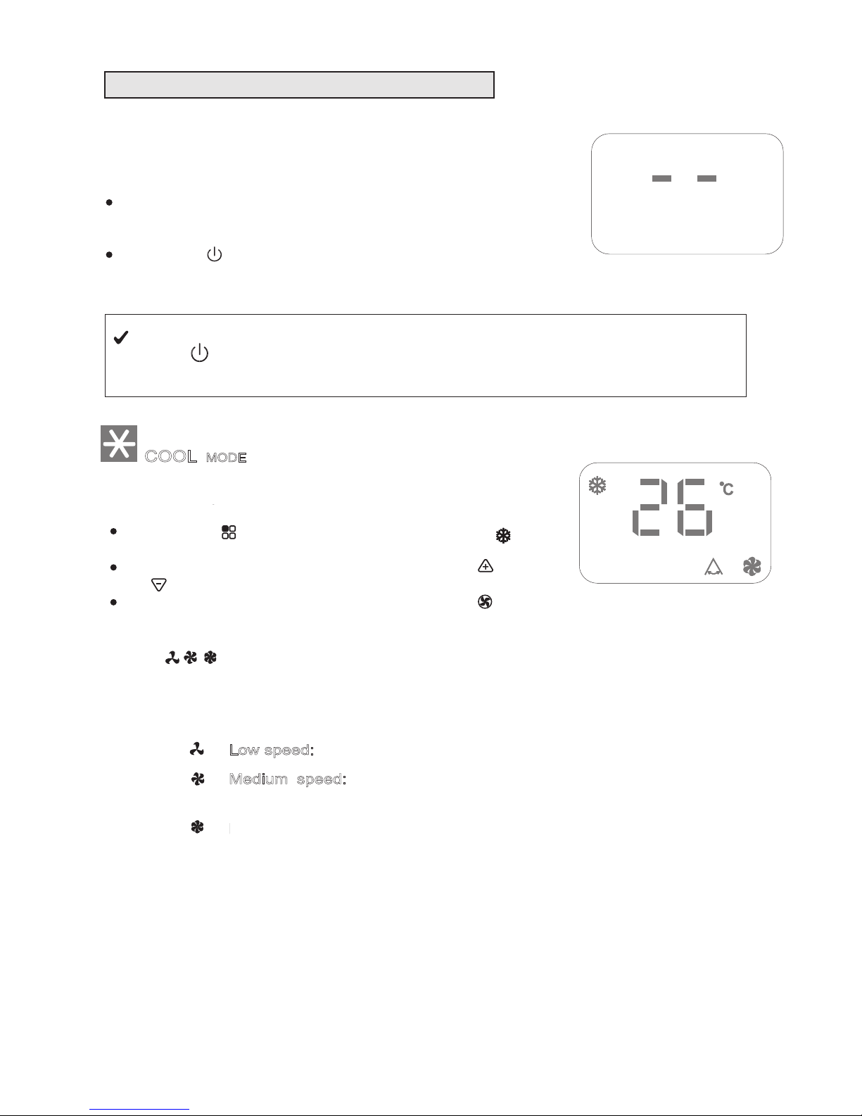
OPERATING FROM THE CONTROL PANEL
The control panel enables you to manage all the main functions
of the appliance, but to fully exploit its potential, you must use the
remote control unit.
T
URNING THE APPLIANCE ON
Plug into the mains socket.
Two lines appear on the display indicating that the appliance
is in standby.
Press the button until the appliance comes on. The last
function active when it was turned off will appear.
Never turn the air conditioner off by unplugging from the mains. Always press the
button , then wait for a few minutes before unplugging. This allows the appliance
to perform a cycle of checks to verify operation.
COOL
MODE
Ideal for hot muggy weather when you need to air conditioning
and dehumidify the room.
To set this mode correctly:
Press the " "
button a number of times until the " "
symbol appears.
Select the target temperature by pressing the " " or
" " button until the corresponding value is displayed.
Select the required fan speed by pressing the " " button.
Three speeds are available:
Maximum speed:
to achieve the target tempe-
rature as rapidly as possible
Medium speed:
reduces noise levels but still
maintains a good level of comfort
Low speed:
for silent operation
OPERATING FROM THE CONTROL PANEL
The control panel enables you to manage all the main functions
of the appliance, but to fully exploit its potential, you must use the
remote control unit.
T
URNING THE APPLIANCE ON
Plug into the mains socket.
Two lines appear on the display indicating that the appliance
is in standby.
Press the button until the appliance comes on. The last
function active when it was turned off will appear.
Never turn the air conditioner off by unplugging from the mains. Always press the
button , then wait for a few minutes before unplugging. This allows the appliance
to perform a cycle of checks to verify operation.
MODE
button a number of times until the " "
Low speed:
for silent operation
MODE
button a number of times until the " "
Medium speed:
reduces noise levels but still
Low speed:
for silent operation
MODE
button a number of times until the " "
Maximum speed:
to achieve the target tempe-
Medium speed:
reduces noise levels but still
maintains a good level of comfort
Low speed:
for silent operation
OPERATING FROM THE CONTROL PANEL
Ideal for hot muggy weather when you need to air condition
and dehumidify the room.
Four speeds are available:
Auto Speed: The three indicators light up means
the fan speed is AUTO and the appliance selects
the most suitable fan speed in relation to the
temperature set on the digital display.
High (Maximum) Speed: to achieve the target
temperature as rapidly as possible

DRY MODE
Ideal to reduce room humidity (spring and autumn, damp rooms,
rainy periods, etc).
In dry mode, the appliance should be prepared in the same way
as for cool mode, with the air exhaust hose attached to enable
the moisture to be discharged outside.
To set this mode correctly:
Press the " " button a number of times until the " "
symbol appears.
In this mode, fan speed is selected automatically by the appliance and can not be set manually.
FAN MODE
When using the appliance in this mode, the air hose does not
need to be attached.
To set this mode correctly:
Press the “ ”
button a number of times until the “ ”
symbol appears.
Select the required fan speed by pressing the F
AN button.
Three speeds are available:
10
N.B.- When operating in very cold rooms, the appliance defrost auto-
matically, momentarily interrupting normal operation. " " appears
on the display. During this operation, it is normal for the noise made
by the appliance to change.
- In this mode, you may have to wait for a few minutes before the
appliance starts giving out hot air.
the set temperature has already been reached.
- In this mode, the fan may operate for short periods, even though
“* ” means only the heat pump model have this function.
Swing function
- This function is useful for select the left / right of air delivery.
- To set this function:
- Select the operating mode( Cool/ Dry/ Fan/ Heat ) as described
above.
- Press the “ ” button, the appliance operates in the previously
selected mode, the symbol “ ”appears.
- Press the “ ” button again, the symbol disappears to indicate
the swing is stop.
High (maximum) speed: for maximum fan power
Using this function will cause the air direction louvres to swing
automatically, directing the air flow left and right.
Begin air conditioner operation by choosing the operating mode (Cool/
Dry/Fan) as described above before performing this procedure.
To select SWING operation:
• Press the swing button - the swing display
will light up and the
louvres will swing automatically
To stop swing operation:
• Press the swing button again - the swing display will disappear
and the louvres will return to the setting before the swing function
was commenced.
11
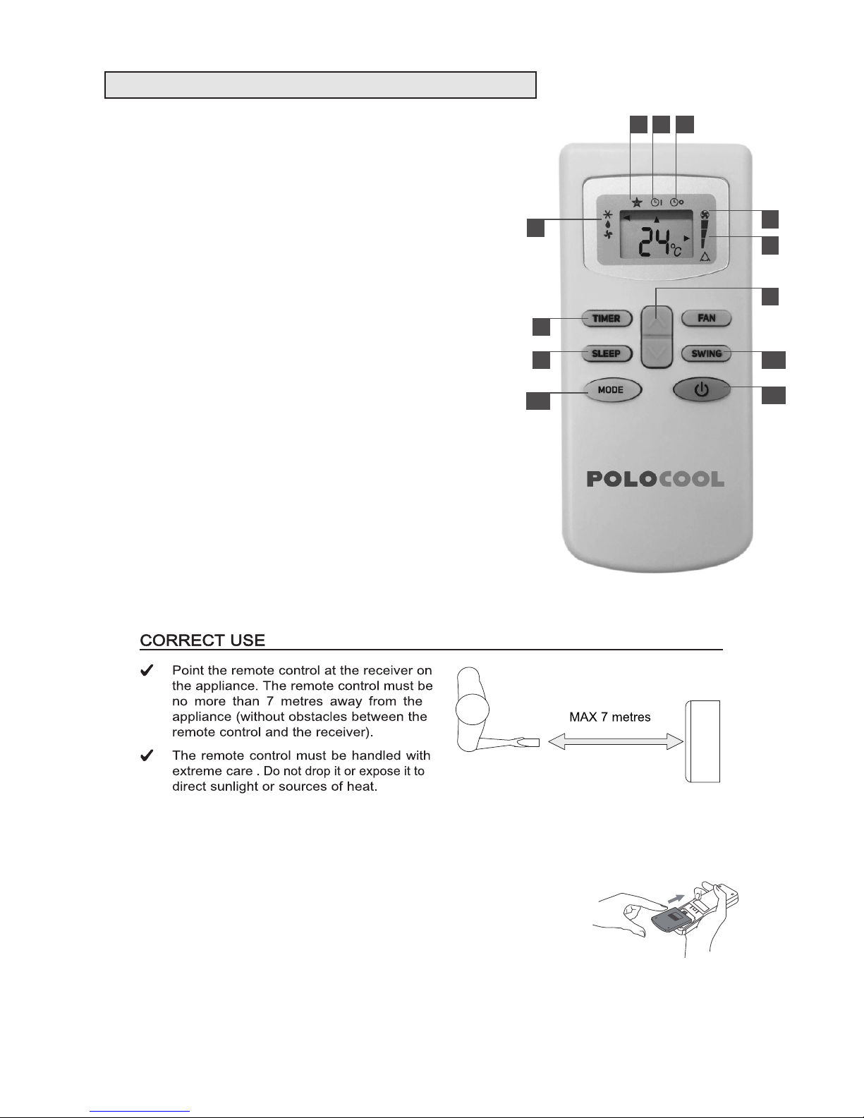
DESCRIPTION OF THE REMOTE CONTROL
1. Mode indicator - COOL / DEHUMIDIFY (DRY) / FAN
2. Sleep indicator
3. Timer on
4. Timer off
5. Auto speed indicator
6. Fan speed indicator
7. (a) increase (+) button
(b) decrease (-) button
8. TIMER button
Press this button to set automatic startup / shutdown
9. SLEEP button
Press this button to set ON/OFF sleep function
10. MODE button
Press this button to select the modes of COOL/DRY
(Dehumidify) /FAN
11. SWING button
Press this button to switch ON/OFF the automatic swing function
12. ON/OFF button
Press this button to switch ON/OFF the appliance
/
INSERTING OR REPLACING THE BATTERIES
• Slide and remove the cover on the rear of the remote control;
• Insert two “AAA” 1.5V batteries in the correct position
(see instructions inside the battery compartment);
• Replace the cover
If the remote control is not used for long periods, remove the batteries.
1
32 4
6
5
7
8
9
10
11
12
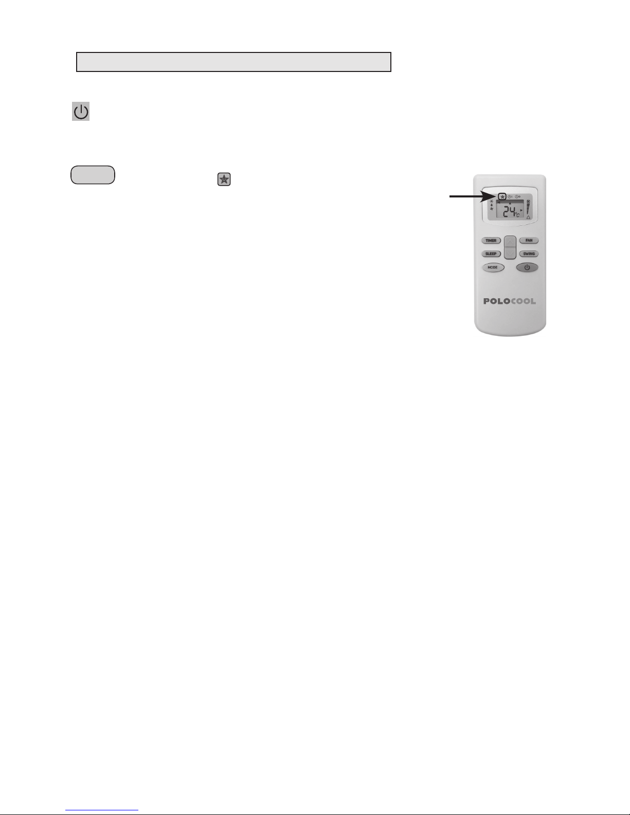
REMOTE CONTROL OPERATION
ON/OFF BUTTON
1. Press the ON/OFF button to turn the unit ON or OFF.
2. Each time the unit is turned ON it will start operation in last selected mode.
REMOTE CONTROL
SLEEP
SLEEP FUNCTION
REMOTE CONTROL OPERATION
ON/OFF BUTTON
1. Press the ON/OFF button to turn the unit ON or OFF.
2. Each time the unit is turned ON it will start operation in last selected mode.
CLOCK
CLOCK BUTTON
1. To set the correct time of the day, press the CLOCK button.
2. The clock display will fash; set the clock using the
UP/DOWN button.
3. Each time the UP or DOWN button is pressed the minute
display will increment/decrement by 1. After the correct
time is set press the CLOCK button to store the set time.
REMOTE CONTROL
C
ON
OFF
h
FEEL
❄
12
OPERATING FROM THE REMOTE CONTROL
Under this function the unit maintains the room temperature at optimum level
with quiet operation. The unit will run in a preset programmed algorithm which
will vary the set temperature after every preset time interval. The unit will be
turned off after 8 hours and will be in STAND BY mode.
Fan speed cannot be adjusted and is always set to low under this function.
TO SET
1. Select the desired mode of operation - COOL or DRY
2. Press the SLEEP button, sleep icon will appear on the display and the
remote which will indicate the unit is set in SLEEP function.
3. In SLEEP function if the unit is running in COOL mode, after each hour the
set temperature is increased by 1°C, this happens for the first two hours
after which the unit will run at (set temperature +2°C) for remaining 6 hours
before it switches off.
4. In DRY mode the dehumidifying power of the appliance is partially reduced
every hour for the first two hours and then the unit will run for 6 hrs at the
reduced dehumidifying power before it goes into STANDBY mode.

TIMER
TIMER FUNCTION
13
The Timer Function is used to set the ON or OFF time interval of the unit.
This function can only be set using the remote control.
Timer ON and Timer OFF can not be set concurrently, only one or the other can be set at any one time.
The air conditioner must be running in the desired operating settings before selecting either the Timer ON
or Timer OFF function, for example Cooling Mode, 25°C Target Temperature, Fan Speed high.
In both timer modes the time interval can be incremented by 30 minutes from 1-10 hours.
Between 10-24 hours, the time interval can be incremented by 1 hour.
In an event of power failure the timer interval will need to be reprogrammed.
TIMER ON
This function is used to start the unit after a specic time interval.
To set the ON time:
1. The unit must be running in the desired operating settings under which you want the
unit to run when it starts up after the selected time interval has elapsed.
2. Press the ON/OFF button on the remote to switch the unit in STANDBY mode.
3. Press the TIMER button; the remote handset will display the time icon and
ON next to it.
4. Press the TIMER button once; the clock display will come up and continue to ash
next to the ON time icon.
5. Set the time interval after which you want the unit to be turned ON using the UP/
DOWN button.
6. Once the selected time interval is set press the TIMER button again to store the time interval in the memory.
7. The unit will start operating in the mode selected when the preset time is reached.
8. To cancel the timer setting, press the TIMER button.
TIMER OFF
This function is used to turn OFF the unit after a specific time interval.
To set the OFF time:
1. The unit must be running in the desired operating settings under which you want the
unit to run during the specified time interval.
2. Press the TIMER button once; the clock display will come up and continue to flash
next to the ON time icon.
3. Set the time interval after which you want the unit to be turned OFF using the
UP/DOWN button.
4. Once the selected time is set press the TIMER button again to store the off time
interval in the memory.
5. The unit will be turned OFF when the preset time is reached and will be in standby
mode.
6. To cancel the timer setting, press the TIMER button.

14
FULL TANK
(safety tank full)
Empty the internal safety tank,
following the instructions in the
"End of season operations"
paragraph.
SELF-DIAGNOSIS
The appliance has a self diagnosis system to identify a number of malfunctions.
Error messages are displayed on the appliance display.
IF
IS DISPLAYED
,
WHAT SHOULD I DO?
L
OWTEMPERATURE
(frost prevention)
P
ROBEFAILURE
(sensor damaged)
The appliance is fitted with
a frost protection device to
avoid excessive formation
of ice.
The appliance starts up
again automatically when
the defrosting process is
completed.
If this is displayed, contact
your local authorised servi-
ce centre.
SELF-DIAGNOSIS
If this is displayed, contact
POLO for advice on
1800 087 840
Empty the internal water tank,
following the instructions in the
“End of season operations”
paragraph.
(water tank full)
15
WATER DRAINAGE METHOD
This air conditioner is equipped with the very latest MIST technology which means that the water tank
generally never needs emptying even in high humidity areas. Water drainage will generally only be required
at the end of the season (see End of Season Operations – page 16)
NOTE
As a safety measure, to positively prevent water spillage, the air conditioner is equipped with a fail safe
device, if, the water tank fills. The unit will completely stop, the control panel displays “
” (FULL
TANK) as mentioned in SELF-DIAGNOSIS in page 14, the compressor and fan will not restart until
the tank has been drained.
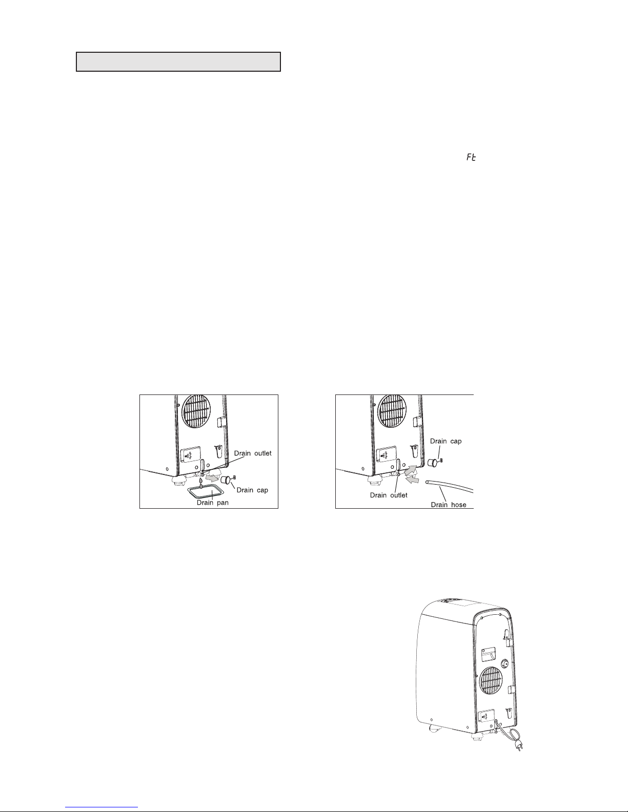
Before draining the water tank (tray) take care not to move the air conditioner as water may spill onto the floor.
Turn the air conditioner off using the on/off switch on the unit or remote control. Then drain the water tank by
unplugging the drain outlet and allowing the water to flow onto the drain pan. The drain pan will not hold the
full contents of the water tank. A number of fills of the drain pan are required. It may be easier (after 3 or 4
pans have been drained in order to avoid accidental spillage when shifting the air conditioner) to wheel the
unit outside, remove the drain plug and drain the water onto the ground.
The water tank is considered sufficiently drained when no more water flows from the drain outlet.
Restart the air conditioner by pressing the on/off button. Ensure that the unit is in COOL or DRY mode. The
compressor will start approximately 3 minutes after the unit is switched on.
NOTE
To completely drain all water from the water tank, tilt the unit by lifting it slightly upwards from
the front until no more water drains from the outlet.
CONTINUOUS DRAINAGE
When operating in dry (dehumidifying) mode continuous drainage can be used to avoid the trouble of manual
drainage, if required.
This appliance is equipped with a second drain outlet half way up the back of the unit for this purpose.
To operate the continuous drain method:
(1) Empty the water tank completely
(2)
Connect one end of the drain hose on the middle drain outlet (pick the
hose end that has a tight fit on this outlet) and lead the other end to
outdoor or other place where it can drain freely. The bottom drain outlet
can also be used but is not as effective as the middle drain outlet as
this outlet puts a greater slope on the drain pipe which drains the water
more quickly and makes the dry mode work more effectively
(3)
Turn on the appliance and select dry mode
When this continuous drainage method is adopted in dry mode, water
removed from the air flows out through the drain hose continuously.

16
CLEANING
Before cleaning or maintenance, turn the appliance off by pressing the button on the control panel or ON/OFF botton on
remote control, wait for a few minutes then unplug from the mains
CLEANING THE CABINET
You should clean the appliance with a slightly damp cloth then dry
with a dry cloth.
Never wash the air conditioner with water. It could be dangerous.
Never use petrol, alcohol or solvents to clean the appliance.
Never spray insecticide liquids or similar.
C
LEANING THE AIR FILTERS
To keep your air conditioner working efficiently, you should clean
the filter every week of operation.
The filters are housed in the intake grille (fig. 29).
Use a vacuum cleaner to remove dust accumulations from the filter. If it is very dirty, immerse in warm water and rinse a number of
times. The water should never be hotter than 40℃.
After washing, leave the filter to dry then attach the intake grille to
the appliance.
socket.
2429
CLEANING
Before cleaning or maintenance, turn the appliance off by pres-
sing the button on the control panel or ON/OFF botton on
remote control, wait for a few minutes then unplug from the mains
CLEANING THE CABINET
You should clean the appliance with a slightly damp cloth then dry
with a dry cloth.
Never wash the air conditioner with water. It could be dange-
rous.
Never use petrol, alcohol or solvents to clean the appliance.
Never spray insecticide liquids or similar.
C
LEANING THE AIR FILTERS
To keep your air conditioner working efficiently, you should clean
the filter every week of operation.
The filters are housed in the intake grille (fig. 29).
Use a vacuum cleaner to remove dust accumulations from the fil-
ter. If it is very dirty, immerse in warm water and rinse a number of
times. The water should never be hotter than 40℃.
After washing, leave the filter to dry then attach the intake grille to
the appliance.
START - END OF SEASON OPERATIONS
START OF SEASON CHECKS
Make sure the power cable and plug are undamaged and the
earth system is efficient.
Follow the installation instructions precisely.
END OF SEASON OPERATIONS
To empty the internal circuit completely of water, remove the cap
(fig. 30).
Run off all water left into a basin. When all the water has
been
drained, put the cap back in place.
Clean the filter and dry thoroughly before putting back.
socket.
2530
2429
2530
2429
MAINTENANCE AND SERVICE
To keep your air conditioner working efficiently, you should clean
the filters every two weeks of operation.
Clean the filters and dry thoroughly before putting back.

17
•
Standard air exhaust hose has been
extended longer than 1.5m?
•
Remove extension, always keep
standard hose length less than
1.5 metres
TROUBLE SHOOTING
Before seeking repair or service, please check the following.
PROBLEMCHECK ACTION
No power to Air Conditioner
•
Is A/C plugged into power supply
outlet?
•
Has fuse blown (circuit breaker
switched off) or A/C switched off?
•
Insert power plug securely into
power supply outlet and turn
power on
•
Turn A/C off, replace fuse wire
(or turn on circuit breaker), turn
A/C back on
Power to Air Conditioner, but unit
does not operate.
Air Conditioner does not cool
after turning on.
•
Is timer on?
•
Wait for timer to count down or
cancel timer setting by pressing
•
Is compressor light illuminated?
•
Wait 3 minutes from turning on,
safety device prevents compressor
(which provides cooling) being
turned on for about 3 minutes.
TIMER button
The compressor and fan has stopped.
•
Is “Ft” displayed on LCD?
•
Drain water
Air Conditioner not cooling
satisfactorily.
•
Has the temperature been set low
enough?
•
Air exhaust hose blocked?
•
Air exhaust hose bent over?
•
Air exhaust hose detached?
•
Window/door opened?
•
Air inlet/outlet blocked?
•
Air filters dirty?
•
Fan speed set at low?
•
Cooling power not enough for the
conditions of area or room?
•
Reduce Temperature setting
•
Clear blockage
•
Always keep the hose at its
shortest length and as straight as
possible
•
Connect the hose
•
Close the windows/doors to
room being cooled
•
Clear blockage
•
Clean air filter
•
Set suitable higher speed
•
Ensure A/C is suitable for
conditions of area and room
Air Conditioner vibrates.
•
Is it leaning or unbalanced?
•
Place on level floor
Lt/PF/Ft appears on the display.
•
See self-diagnosis section
Wait
TECHNICAL SPECIFICATIONS
Mains voltage
Maximum absorbed power in air conditioning
Refrigerant
Cooling capacity
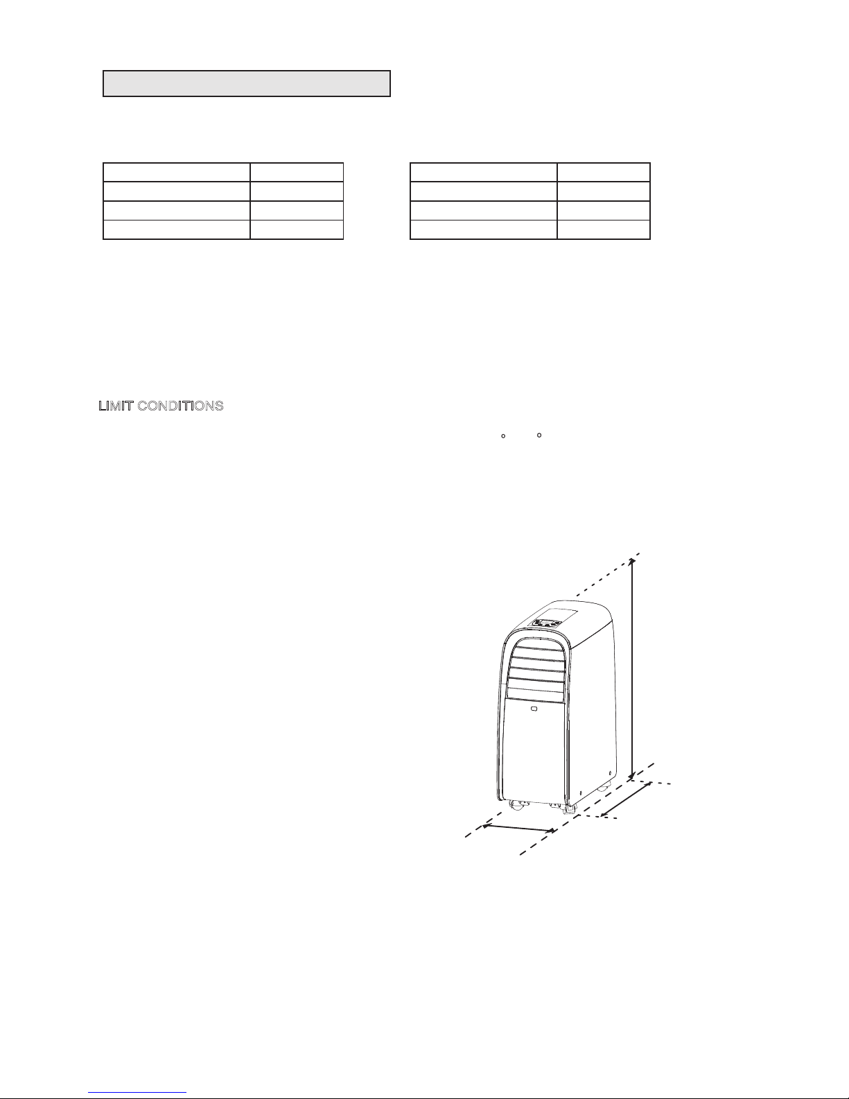
LIMIT CONDITIONS
Temperature of room in air conditioning
SIZE OF APPLIANCE
Width
Height
Depth
263 mm
700 mm
506
mm
. .
. .
. .
see rating label
10℃-25℃
(Cooling)
(Heating)
Volume of water tank
1 L
Protection degree
IPX0
18 C-35
O
O
C
506 mm
700 mm
263 mm
18
TECHNICAL SPECIFICATIONS
SIZE OF APPLIANCES
Polocool EX10
Rated Voltage 240 Volts
Rated Power Input 1100 watts
Refrigerant/Charge R410A/0.56kg
Cooling Capacity 2,900 watts
Polocool EX12
Rated Voltage 240 Volts
Rated Power Input 1200 watts
Refrigerant/Charge R410A/0.59kg
Cooling Capacity 3,500 watts
283 mm
283 mm
 Loading...