


DEC 2015
USER MANUAL
POLO ‘C’ SERIES CONVECTION
PANEL HEATERS
The POLO “C” Series range of convection panel heaters consists of eight models – four with a digital timer and four without a digital timer:
|
|
|
|
|
|
|
|
POLO Model CT |
POLO Model C |
Watts |
Amps |
Length |
Height |
Thickness |
Weight |
(with digital timer) |
(without digital |
|
|
(mm) |
(mm) |
(mm) |
(kg – |
|
timer) |
|
|
|
|
|
approx) |
CT100 |
C100 |
1000 |
4.2 |
545 |
452 |
75 |
6.5 |
CT150 |
C150 |
1500 |
6.3 |
700 |
452 |
75 |
8 |
CT200 |
C200 |
2000 |
8.3 |
890 |
452 |
75 |
10 |
CT240 |
C240 |
2400 |
10.0 |
1035 |
452 |
75 |
12 |
IMPORTANT SAFETY ADVICE
(1)The wall bracket supplied with the heater must be used to attach the heater to a wall.
(2)To locate the heater in a bathroom (ie containing a bath or shower) the heater must be located so that the controls cannot be operated by a person in the bath or shower. The heater must be located at least 600mm from a shower screen or bath surround. If in doubt, the services of a qualified electrician or licensed electrical contractor must be used to determine a suitable location in a bathroom.
(3)Do not use outdoors – indoor use only.
(4)Do not locate the heater immediately below a fixed socket outlet.
(5)The heater may be installed in front of a fixed socket outlet concealing the power lead and plug.
(6)Do not cover the heater or place material or garments on the heater.
(7)Do not obstruct the front finned air outlet of the heater or obstruct the air circulation around the heater by curtains or pushing furniture up against it. This could cause overheating and a fire risk.
(8)The heater carries the warning “Do not cover” indicating that in order to avoid overheating, do not cover the heater.
(9)If used with the included castors, do not use this heater in the immediate surroundings of a bath, a shower or a swimming pool.
(10)If the supply cord is damaged, it MUST be replaced by the manufacturer’s service agent or similarly qualified person to avoid a hazard.
(11)When using models CT240/C240 – 2400 watts, do not share the power supply with other appliances. Do not connect to multiple power outlets on extension leads.
(12)If any abnormal noise ever comes from the heater or control panel, switch off and contact Polo immediately for advice.
(13)WARNING – THE SURFACES OF THIS HEATER CAN BE HOT ESPECIALLY THE FRONT GRILL AND THE TOP OF THE HEATER
Momentarily contact with any part of the heater should not cause injury.
This appliance is not intended for use by persons (including children) with reduced physical, sensory or mental capabilities, or lack of experience and knowledge, unless they have been given supervision or instruction concerning use of the appliance by a person responsible for their safety. Children should be supervised to ensure that they don’t play with the appliance
Page 1

GENERAL
The POLO ‘C’range of convection panel heaters are designed for fixed mounting on the wall bracket supplied with each heater, or for portability on included castors. When used with the included castors, do not use this heater in the immediate surroundings of a bath, shower or indoor swimming pool.
The POLO convection panel heaters should only be operated in the upright position as shown in Fig 1 with the front outlet grill at the top and the controls on the right hand side.
All models are splash proof to IP24 and are suitable for use in bathrooms subject to the safety advice above.
The heater is fitted with a cable and plug and is designed to be connected to a standard 10 amp socket outlet located behind, or at the side or below the heater.
The heater is fitted with a cable approx 1.4metres long and a three pin plug.
For economical operation do not use the heaters 24 hours a day. We recommend you set the thermostat wheel to between 18-20 degrees Celsius and switch off the heaters when the room is not in use.
WALL MOUNTING
IMPORTANT – The wall bracket supplied with the heater must be used.
Minimum distances from objects
For objects of all types eg furniture, curtains, hangings or textiles or other flammable or nonflammable materials, the following minimum distances from the unit must be observed – see Fig 1
To the front air outlet grill |
- |
500mm |
To the sides |
- |
100mm |
To the top |
- |
150mm |
To the underside |
- |
100mm |
Air must be able to enter the bottom of the heater unobstructed and be able to escape unobstructed through the front grill.
The unit can only be used as freestanding by using the included castors
Do not stand on the unit when it is mounted on a wall.
DO NOT locate the heater immediately below a fixed power point.
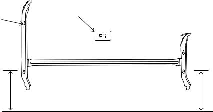
Fig 1 – Minimum distances from objects
Page 2
INSTRUCTIONS FOR WALL MOUNTING
1.This heater may be mounted in front of a standard 10 amp socket outlet with the plug inserted. See Fig 2. Ensure the heater fully covers the socket outlet and plug which results in a very clean looking installation.
2.Remove the wall bracket from the back of the heater by pressing down on the two metal tabs on the top of each end of the bracket and pulling it away from the heater. A long screw driver may be required to press the tab situated at the bottom of the plastic control housing. Lift the two bottom tabs of the wall bracket away from the heater through slots in the back of the heater.
3.Using the wall bracket as a template, and, keeping a minimum 215mm off floor level to the bottom holes in the wall bracket, carefully mark the position of the four plasterboard anchors or wallmates (locating a stud is not necessary), using the holes in the wall bracket as a guide.
These anchors(not supplied) should be able to support a load of 5kg each. If a stud is accidentally located secure the bracket there using wood screws. See Fig 2. Keep the wall bracket level by placing a spirit level on the horizontal rail of the wall bracket.
4.Install the four self drilling plasterboard anchors. Insert 8 gauge zinc coated (corrosion protected) self tappers through the holes in the wall bracket and into the wall anchors. Tighten the self tappers securely. Check that the wall bracket is level by placing a spirit level on the horizontal rail of the wall bracket.
5.Re-attach the heater to the wall bracket by locating the slots in the bottom of the heater onto the wall bracket. Then locate top slots and push heater firmly into the metal tabs until it clicks securely into position. Use a long screw driver to press the two metal tabs down to remove the heater from the wall bracket in the future.
Standard 10 amp switched socket outlet (heater can be installed in
Mark 4 holes using front of this outlet if desired) bracket as a guide.
Install 4 plasterboard anchors into plaster walls. Insert screws into these anchors to hold bracket.
215mm |
215mm |
min |
min |
Floor
Fig 2 – Wall bracket showing how to attach to a wall
Page 3
 Loading...