

Polo SB-B08, SB-A08, SB-C2-4, SB-A04, SB-A03 User Manual

POLO Filters
Type : SB-A0.4
Job No.: B05_3643
Customer: Haurenherm
Order no.: per FAX 19.10.05
Important :
Read these Instructions before commissioning. The manufacturer cannot accept
liability for damage or malfunction due to non-observance of these Instructions.
The right to make technical changes essential to development and/or
improvement is reserved. (BEMO_01E P.1)
Keep these Instructions in a safe
place for future reference.
CE Operating Instructions CE
Manufacturer
POLO-FiltertechnikBremen-GmbH
In den Ellern 6
28832 Achim
Tel.: +49-421/238 02 -0
Fax : +49-421/238 02 99

Polo Filter-Technik Bremen
Drafted by: M. Schwarzer Stand: 01.05
Operating Instructions
General Notes
BEMO_01E/7
Page 2 of 6
EU conformity declaration
within the meaning of the EU Machinery Guideline 98/37/EC, Appendix II A
EU Guideline on Electro-magnetic Compatibility 89/336/EEC
EU Guideline „Low-voltage“ 73/23/EEC
The filter described on the previous page (BEMO_01E P.1) was designed, developed and
manufactured in accordance with the EU Guidelines mentioned above on the sole
responsibility of
POLO Filter-Technik Bremen GmbH
In den Ellern 6
28832 Achim
Germany
The following harmonised standards apply:
• DIN EN ISO 12100-1, Safety of Machinery
• DIN EN ISO 12100-2, Safety of Machinery
• EN 60 204.1:1998-11, Electrical Equipment of Industrial Machinery
The following standards were applied in evaluating the electro-magnetic compatibility of the
products:
• DIN EN 61000-6-4:2002; EMC Generic emission standard of Industrial Machinery
• DIN EN 61000-6-2:2002; EMC Generic Immunity standard of Industrial Machinery
Complete technical documentation is available.
The Operating Instructions for the machinery are also available.
Bremen, 31.01.2005 Management
Place, Date Signature Günter Grigo Details of signatory

Polo Filter-Technik Bremen
Drafted by: M. Schwarzer Stand: 01.05
Operating Instructions
General Notes
BEMO_01E/7
Page 3 of 6
1 Basic notes on safety
These Operating Instructions contain the most important information on safely operating the machinery.
1.1 Obligations and liability
Observe the information given in these Instructions.
Knowledge of the basic safety information and regulations is the fundamental pre-condition for the safe use and
trouble-free operation of the plant. These Operating Instructions, particularly the safety information contained
therein, are to be adhered to by all persons working on the plant.
In addition, the generally valid accident prevention rules and regulations as well as the operator’s internal
working, operational and safety regulations must also be adhered to.
The staff installing and operating the plant before it is commissioned must read these Operating Instructions.
These Instructions must always be available at the plant site.
Dangers involved in plant use
This plant is state-of-the-art and compliant with the generally acknowledged safety engineering rules in its
design. Nevertheless, plant operation may involve some risk to life and limb for the operator or third parties or
even cause damage to the plant or other property. The plant is only to be used
• for the purpose for which it was designed, and
• only when it is in good operational condition from the safety engineering standpoint.
Malfunctions that may affect safety must be corrected immediately they arise.
Guarantee and liability
Our “General Conditions of Sale” apply. These are available to the operator by the time contract is made at the
latest. Guarantee and liability claims for damage to persons or property are excluded when due to one or more
of the following causes:
• improper use of the plant;
• improper installation, commissioning, operation or maintenance of the plant;
• plant operation with defective safety equipment or with safety and protective equipment improperly installed
or defective;
• non-observance of the information in the Operating Instructions concerning transport, storage, installation,
commissioning, operation, maintenance and equipping of the plant;
• unauthorised technical modification of the plant;
• any other form of unauthorised modification of the plant (e.g. drive system);
• defective monitoring of plant components subject to wear;
• improperly performed repairs, and/or
• emergencies due to foreign bodies or force majeure.
1.2 Safety symbols
Warning
This symbol is to be found accompanying all safety-at-work information involving risk to life and limb.
Observe this warning and be very cautious where it applies. Pass all such information on to other
operators. The generally valid safety and accident prevention rules must be observed as well as the
information in these Operating Instructions on the subject.
Caution
This symbol denotes important information on proper treatment of the plant. Non-observance may lead
to plant malfunction or damage to the surrounding area.
)
Polo Filter-Technik Bremen
Drafted by: M. Schwarzer Stand: 01.05
Operating Instructions
General Notes
BEMO_01E/7
Page 4 of 6
1.3 Staff qualifications and training
The operator must ensure that
• operating, maintenance, service and installation staff are properly qualified to perform their functions;
• operating, maintenance and service staff are aware of all relevant safety information and observe same;
• staff responsibilities for operation, modification and maintenance are clearly defined, and that all
• trainees only work on the plant under experienced supervision.
1.4 Protective equipment
All the plant protective equipment must be properly installed and fully functional before the plant is operated.
Protective equipment may only be removed when
• the plant has been brought to a standstill, and
• it is secured against re-starting.
Protective equipment is to be properly installed by the operator in case of incomplete component delivery.
All the safety and danger labelling on the plant must be kept clearly legible and renewed whenever necessary.
1.5 Maintenance, service and installation work safety information
Maintenance work must be performed only when the plant is at a complete standstill on principle.
All safety equipment is to be re-installed and/or made wholly functional again immediately on completion of any
work on the plant.
The plant must not be operated if any part/s is/are damaged (plugs, wiring, etc.), their proper functioning not
guaranteed, or when damage is ascertainable or can safely be assumed.
Caution! The plant starts automatically!
The plant is to be completely cut off from all power
sources before working on it!
1.6 Modification and spare part manufacture
Modifications and changes to the plant may only be carried out by agreement with the maker and under
adherence to all relevant safety rules.
Use of original spares and accessories authorised by the maker is a major safety factor. No liability whatsoever
can be accepted for any damage due to the use of any other parts.
Polo Filter-Technik Bremen
Drafted by: M. Schwarzer Stand: 01.05
Operating Instructions
General Notes
BEMO_01E/7
Page 5 of 6
2. Transport and handling
2.1 Liability
POLO accepts no liability for transport damage or for breakage. Please check the plant immediately on delivery
and advise any claim/s to the last shipper; this applies even if the packaging seems undamaged. We
recommend leaving the plant, equipment and packaging in the condition in which the damage was ascertained
to ensure the validity of any claims that may be enforceable against third parties.
Please advise us of any other complaints you may have within six days of receipt of the shipment in question.
2.2 Transport
The plant may only be transported in its original packaging until it is commissioned. The maker is to be advised
immediately of any damage.
If the plant is moved within the works, all connections must be undone first. Plant movement must be carried out
in such a manner that no damage is caused. Should any such damage occur despite this, then an expert must
check the plant before it is re-started and, if necessary, repair it.
Allow for the weight given in the Operating Instructions when transporting the
plant.
Use a forklift or crane with carrying ropes/cables of the right strength.
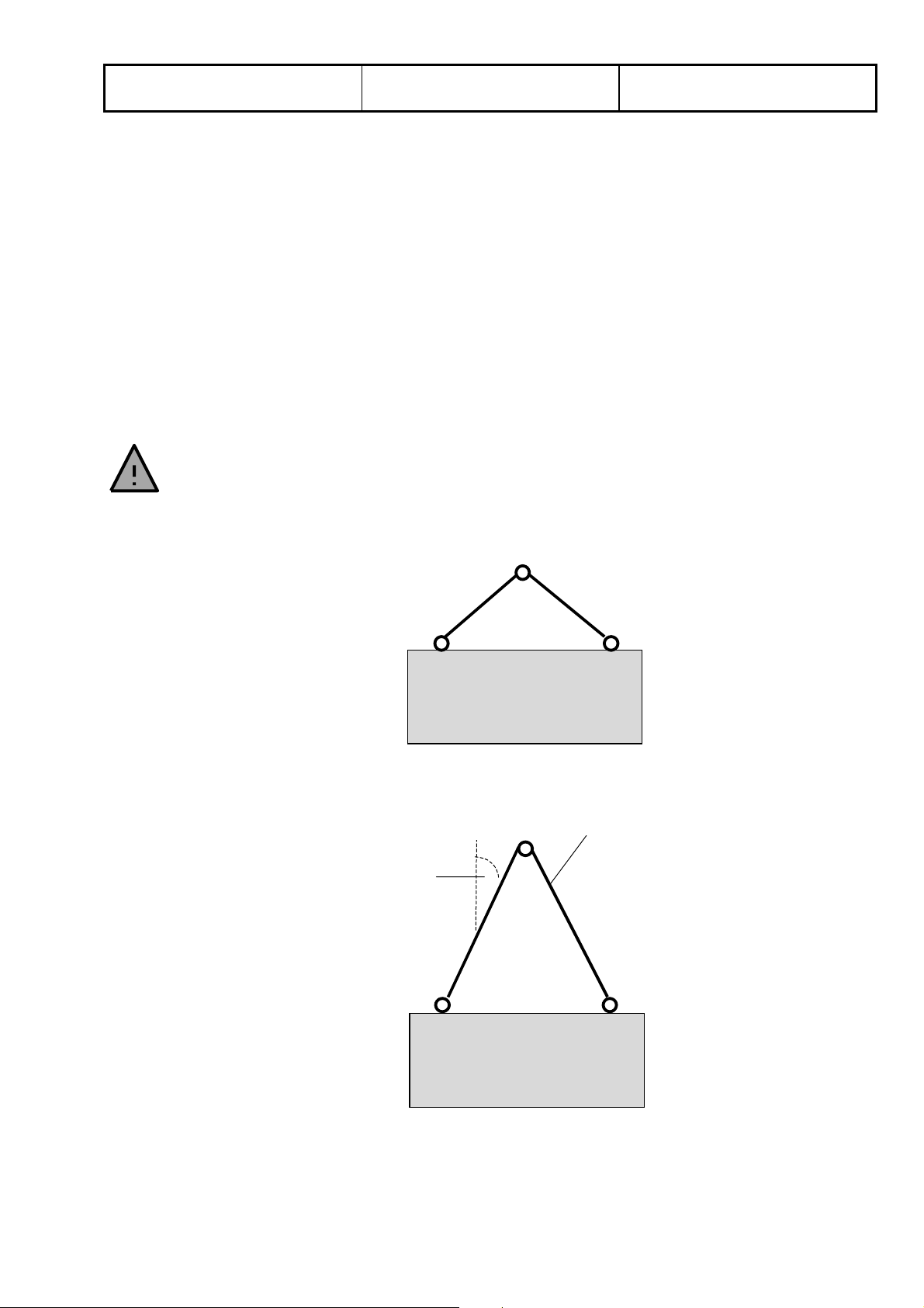
2.3 Transport carefully
Wrong:
Right:
30°
≤
Carrying rope/wire
Polo Filter-Technik Bremen
Drafted by: M. Schwarzer Stand: 01.05
Operating Instructions
General Notes
BEMO_01E/7
Page 6 of 6
3. Safety identification on the filter plant
Safety instructions, in the shape of pictograms, have been attached to the filter plant in a number of places. In
order to avoid danger to operating personnel or third parties, these instructions must be followed!
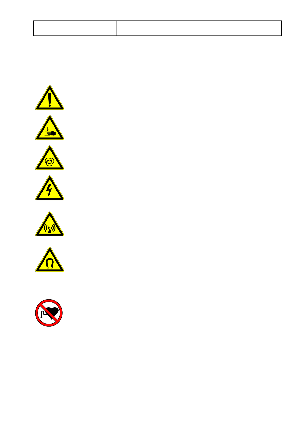
3.1 Warning signs (black with yellow background)
Warning of a dangerous position (general)
Warning of the danger of injury to the hands (e.g. cutting, crushing ...)
Warning of the automatic starting up of the mashine
Warning of dangerous electrical voltage
Warning of electromagnetic fields
Warning of manetic fields
3.2 Prohibition sign (red)
Prohibited for persons with heart pacemakers

Polo Filter-Technik Bremen
Drafted by: M. Schwarzer Issue: 03.08
Operating instructions for
Slope Bed Filter SB
BEMO_09E/6
Page 1 of 8
1. Technical data:
1.1 Machine details (information shown on filter type plate)
Please enter the information shown on the filter type plate in the following table. In the event that problems
should require remedying, this information can help in avoiding unnecessary delays.
Type
Order No.
Further information relating to your filter (max. flow rate, weight etc.) is to be found in the table in the
accompanying brochure.
1.2 Correct use of the filter unit
The equipment is exclusively designed for separating liquids, the composition of which is defined in the order
confirmation. Use of the equipment for filtering other substances is prohibited. Incorrect use of the equipment
can jeopardise the life and limb of the user and/or that of third parties or can prevent efficient operation of the
equipment.
2. Setting up and starting up
When working on the system, please take note of the danger and safety instructions attached to the filter. In
order to avoid any damage to the filter aid, it must be covered during assembly (e.g. by a welding blanket).
2.1 Installation
2.1.1 Filter installation (if supplied without tank)
If you have obtained a filter without the accompanying tank you must erect the filter above the existing collecting
trough. Beforehand it is to be ensured that the mounting unit is able to take the weight of the filter plus the
weight of the medium to be filtered. During installation care is to be taken that the filter is completely flush and
level and unable to slip.
2.1.2 Installation (if supplied with tank)
Position the filter, with the collecting trough beneath, in the intended position. Care is to be taken that the
equipment is level and firmly seated.
The equipment must be level in order to ensure that the medium to be filtered is evenly distributed over the filter
fabric.
Polo Filter-Technik Bremen
Drafted by: M. Schwarzer Issue: 03.08
Operating instructions for
Slope Bed Filter SB
BEMO_09E/6
Page 2 of 8
2.2 Connecting the equipment
Install the return channel plus the machine supply line. If the filter is to be fed using a pump, pipes of suitable
diameter have to be used in order to lower the speed of the liquid reaching the intake distributor to a minimum.
The pipes and connector channels to the machine to be supplied have to have a certain rate of fall so that the
liquid flows quickly and leaves no deposits. The use of bends should be avoided.
If rubber or plastic pipes are used, their length is to be precisely calculated in order to avoid air pockets in which
deposits would certainly form, eventually blocking the pipes.
2.3 Electrical connection
The filter equipment comes ready to be connected and must simply be connected to the machine as per
enclosed wiring diagram.
Once connection work is completed, the entire electrical installation must be checked as per VDE (Association
of German Electrical Engineers). If connection has not been carried out professionally, no claims will be
accepted under warranty.
2.4 Starting up the plant
Please check whether the filter aid is positioned correctly and has not been damaged. If this is the case, the
plant can be filled. Please check continuously that all connecting pipes do not leak.
When filling up for the first time, please note the max. fill level of the tank. Details are listed in the construction
plans. When filling the tank at a later date, the liquid still in the system must be taken into consideration to avoid
the system overflowing.
If the filter system has been equipped with a switching cabinet, the main switch must be operated and the
control voltage must be switched to “ON“ when starting it up for the first time. Other necessary details are listed
in the enclosed electrical plans.
All control devices (float switches) have been pre-set and checked at the factory. However, during the starting
up process, the operator must observe all functions and if necessary correct them.
All pumps must be equipped with sliders and pressure gauges. They must be set in accordance with the points
specified in the constructions plans. After these points have been reached, fully automatic operation
commences. If there are no leaks, the plant is operational.
3. Inspection and maintenance work
Caution! Equipment starts up automatically!
Prior to carrying out any work on the equipment, switch to neutral and stop
conveyance of impure medium!
Caution! Some types of impurities and some types of
impure media can cause injury (e.g. cuts or burns).
Therefore it is necessary to wear suitable protective clothing!
Polo Filter-Technik Bremen
Drafted by: M. Schwarzer Issue: 03.08
Operating instructions for
Slope Bed Filter SB
BEMO_09E/6
Page 3 of 8
3.1 Filter fleece
We have equipped this filter with fleece type ________.
)
However, we can also supply approximately 20 other fleece qualities from stock.
Depending on the version being used, fleece consumption is monitored using a fleece limit switch with a visual
or acoustic alarm or must be monitored by means of regular sight checks.
Care is to be taken that the equipment is never operated without the use of a filter
)
fleece.
When the roll of fleece is almost used up it must be replaced.
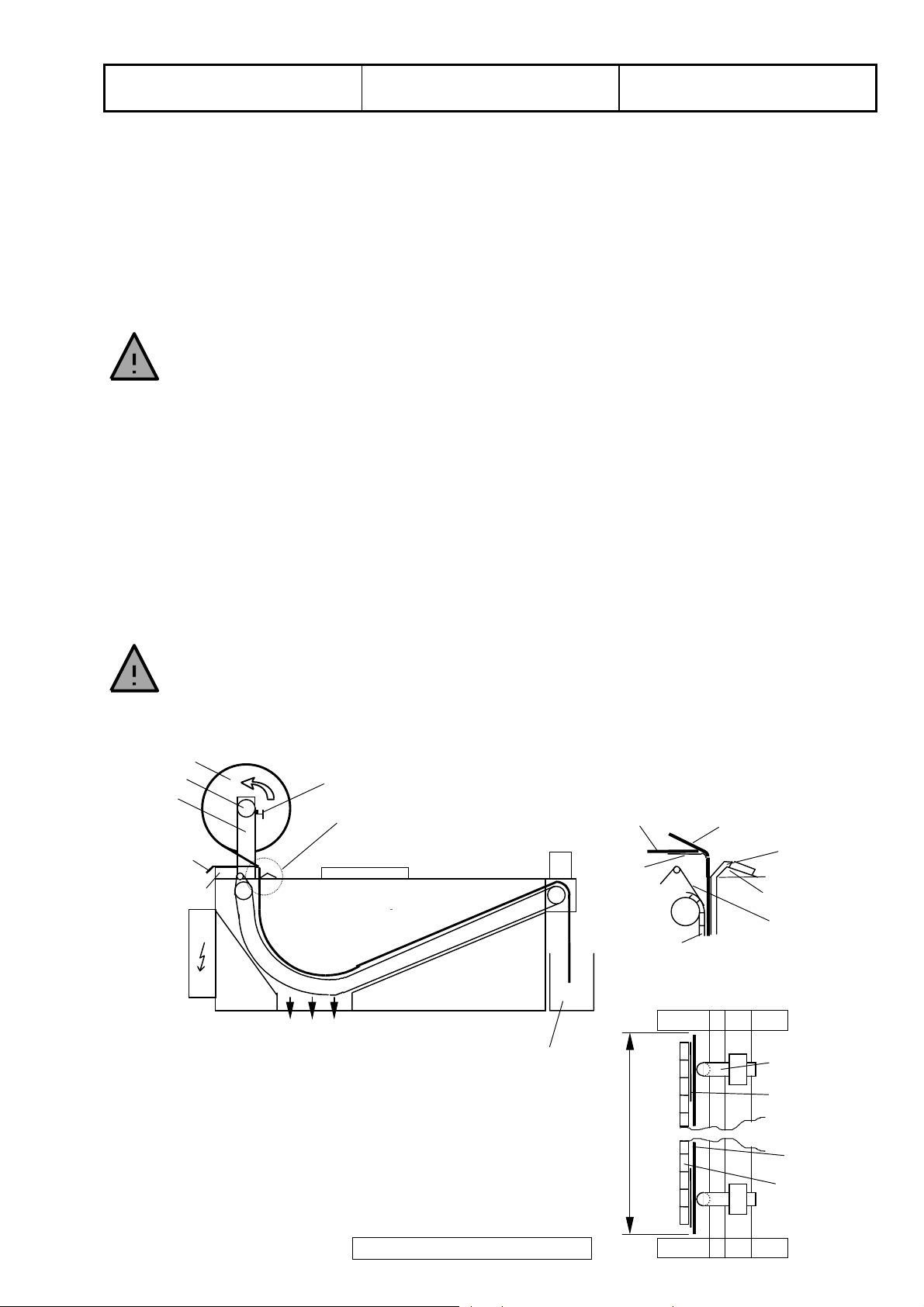
Caution! Sudden start-up of conveyor chain may result in injury!
Fig. 3.1 shows how the fleece roll is being changed.
First, loosen the clamps (1) on either side of the fleece roll holder (2), take out the plastic tube (3) and remove
the cardboard tube from the old fleeceroll. Then push the plastic tube in the new fleece roll (4) and position in
the fleece roll holder.
Care must be taken to make sure that the direction of fleece rotation is correct.
)
(see Fig. 3.1)!
The direction of rotation of the fleece roll must be changed in the case of fleeces
)
with defined dirt and clean sides (Types 380/400/480)!
Centre the fleece roll and secure from moving by tightening the clamps. Some play is necessary so that the
fleece roll can turn properly.
Place the new fleece over the rest of the old roll and direct it down into the gap between the cover (5) and the
angle (6).
NEVER touch the chain!
Danger of injury!
Lift the float in order to trigger the band transport and to transport the fleece untill the old fleece cannot be seen
anymore (approx. 500 mm).
4
3
2
old fleece
(approx. 500mm)
5
1
A
old
fleece
5
conveyor
Detail A
new fleece
side gasket
(firm)
6
rotating seal
View from above:
dirt box
Fig. 3.1 Replacing the fleece roll
side gasket
(firm)
rotating seal
fleece
width of fleece
conveyor
chain
Polo Filter-Technik Bremen
Drafted by: M. Schwarzer Issue: 03.08
Operating instructions for
Slope Bed Filter SB
BEMO_09E/6
Page 4 of 8
3.2 Dirt box
The dirt box ought to be regularly checked.
Do not allow too much used fleece to build up in the dirt box!
)
Otherwise there is a danger of the used fleece becoming wedged in the (returning) conveyor chain.
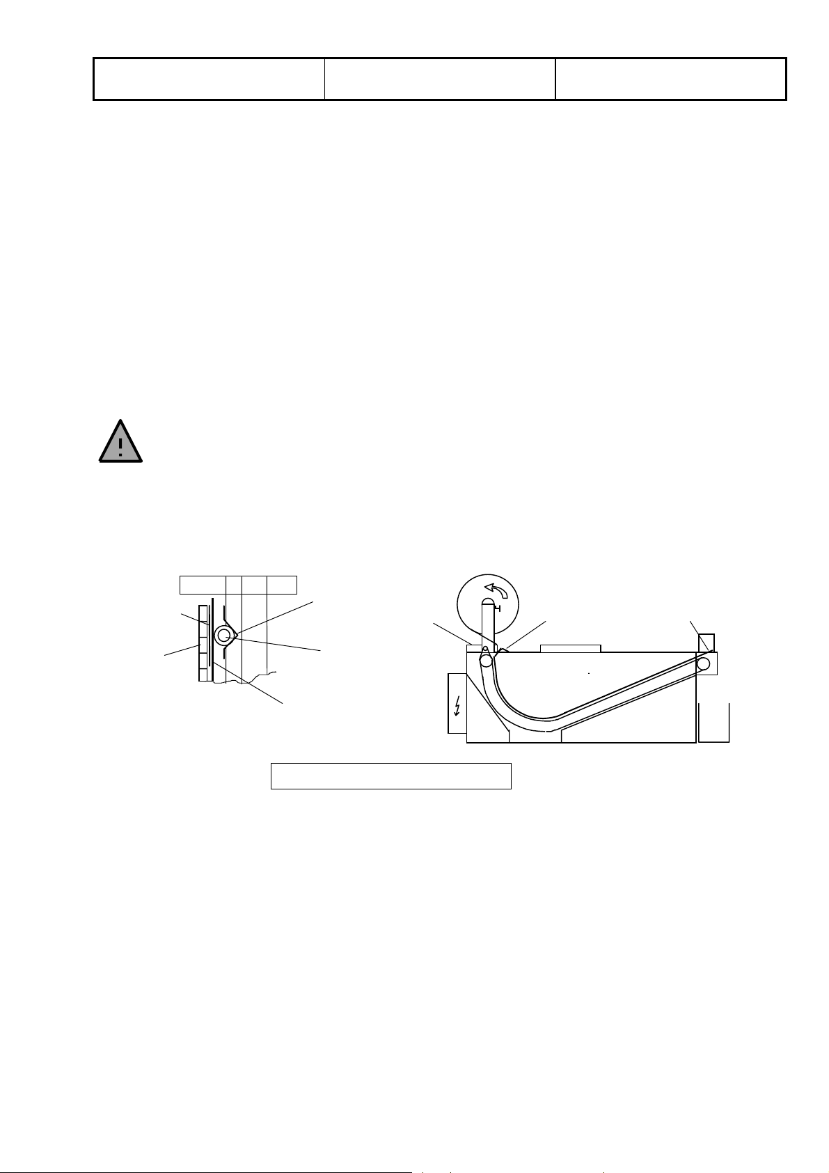
3.3 Side gasket (PTFE-tube with core)
The condition of the side gasket must be checked every 2 months and the gasket replaced if necessary.
Caution: soiled medium may enter the clean tank if the side gasket is damaged!
)
Before replacing the gasket the filter must be emptied by cycling the filter mat forward, and the intake of new
medium must be interrupted.
After emptying, unscrew the collar band and advance the side gasket to the discharge side by cycling the filter.
The PTFE tube is threaded with its open side into the vee-guide between the cover and the angle at the filter
fabric intake side (see fig. 3.2). By lifting the float switch the belt cycle is triggered and the gasket is fed through.
NEVER touch the chain!
Danger of injury!
After feeding through the gasket, it is left hanging loose at the discharge side. On the feed side, the gasket must
be bent around the angle edge and fixed with the collar band. Please ensure that the metal pin is located
underneath the collar band.
Make screw
connection with
clamping ring
here
Let it hang loose
here
Undergasket
Conveyor
chain
Veeguide
Cover
Side gasket
Fleec e
Fig. 3.2 Replacing the side gasket
Polo Filter-Technik Bremen
Drafted by: M. Schwarzer Issue: 03.08
Operating instructions for
Slope Bed Filter SB
BEMO_09E/6
Page 5 of 8
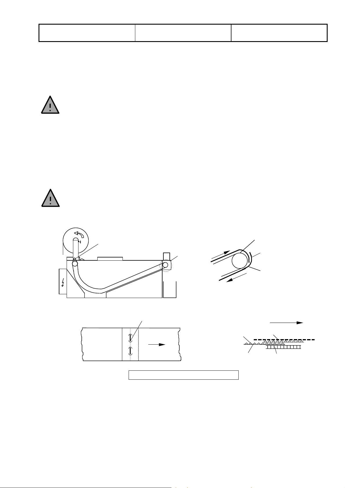
3.4 Undergasket (rotary)
If the filter mat is damaged during operation of the filter it may be possible that the undergasket is damaged. In
this case it must be replaced.
To do this, first interrupt the intake of new medium and empty the filter. Then remove the filter mat from the
filter. Unscrew the cover on the feed side. Trigger the belt cycle until the connection pin at the front of the filter is
visible.
NEVER touch the chain!
Danger of injury!
Pull out the pin and, using the belt cycle, feed the undergasket out of the filter.
When fitting the new gasket, care must be taken to place the smooth side towards the transport chain (see fig.
3.3).
Connect the gasket to the transport chain on the discharge side and feed to the back by triggering the belt
cycle. There, remove the gasket from the chain, feed it around the deflection roller and into the gap between the
transport chain and the PTFE tube. Trigger the belt cycle and feed the gasket through to the front side.
Connect both ends with the pin. Take care to ensure that the upper end is located at the back (see detail A in
fig. 3.3).
The connection pin must be inserted such that the ends are et the smooth side.
)
Wear suitable protection (gloves) when fitting the pin to prevent stab injuries.
After replacing both undergaskets the cover must be put back in place. Then the fleece can be put on as
described at 3.1. However, the belt needs to be cycled to the discharge side.
Detail A
deflection
shaft
View from above:
connection pin
(ends at bottom)
direction of
feed
A
rough side
smooth side
conveyor chain
connect with
pin here
undergasket
direction of
feed
fleece
conveyor
chain
Fig. 3.3 Connecting the undergasket
3.5 Fleece limit switch
If the equipment is fitted with a fleece limit switch then its function must be checked during fleece roller changes
in order to ensure that the equipment is not accidentally operated without the filter fleece. Furthermore it is to be
ensured that the switch is not mechanically damaged (e.g. bent), which could alter the switching points.
Polo Filter-Technik Bremen
Drafted by: M. Schwarzer Issue: 03.08
Operating instructions for
Slope Bed Filter SB
BEMO_09E/6
Page 6 of 8
3.6 Float switch
All POLO-Filter-Technik GmbH float switches are mechanical, buoyancy-dependent control elements. Adhering
particles of dirt are capable of altering the switching points and must therefore be dealt with promptly. This is an
inspection which must to be carried out at least once per week.
If the float switch does not function correctly, the filter unit may overflow.
)
3.7 Greasing
This special design of this filter makes greasing unnecessary.
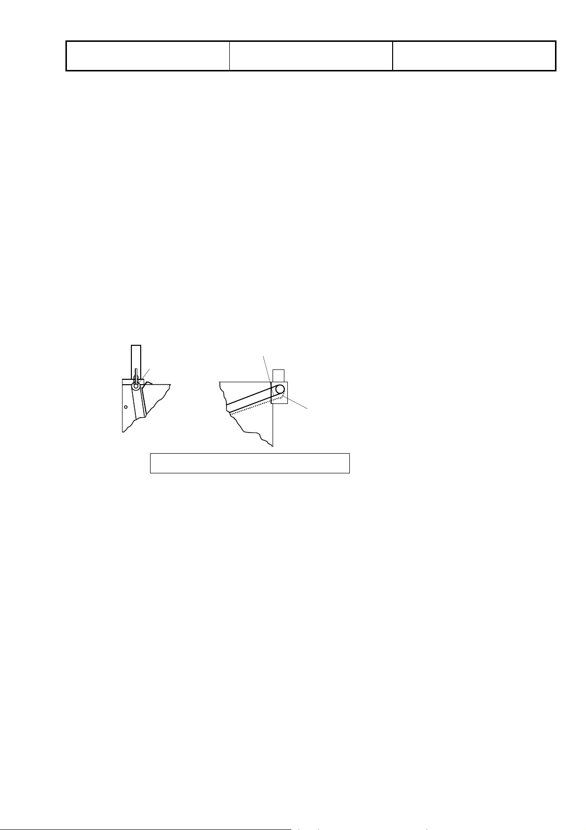
3.8 Transport chain
The tension of the transport chain must be checked once a month. As the chain is self-tensioning, there is no
chain adjuster. This transport chain balances any play under tension. If the chain no longer transports correctly
(chain jumps), it must be shortened or possibly be replaced.
Type SB-B1.6 is an exception. With this type the chain tension must be set by means of 2 tension jacks located
at the deflection shaft of the conveyor chain. Normally the contact angle of the drife shaft is nearly 180°. If it is
fallen down to 100-110°, the chain must be re-tensioned with the chain tensiners at the deflection shaft
(see fig. 3.4).
chain tension
correct
chain tensioner
chain too long
Î
re-tension
Fig.3.4 Adjusting transport chain tension
3.9 Additional maintenance
If your filter plant is equipped with additional components (e.g. magnetic filters, belt skimmer, hasp...) please
refer to the respective chapters of these operating instructions on how to perform additional maintenance work.
The manufacturer’s regulations apply to all pumps and drives. More details are listed in the enclosed data
sheets and documentation.

Polo Filter-Technik Bremen
Drafted by: M. Schwarzer Issue: 03.08
Operating instructions for
Slope Bed Filter SB
BEMO_09E/6
Page 7 of 8
4. Identifying and remedying faults
4.1 General
Quick fault analysis can be carried out using the following list. When faults occur, the user is usually able to deal
with them himself. If this should not prove possible, the probable cause of the fault can be identified over the
telephone, using this fault analysis.
The equipment may only be repaired by competent personnel. In the event of
)
problems with the equipment please contact the manufacturer.
Because of irregular dirt concentration, the filter may be overloaded for short periods of time.
As a result of this:
• The level of liquid continues to rise
• An overflow alarm is triggered
• The belt cycle is continuous
This state is NOT NORMAL! If the plant does not correct itself within a very short period of time, you must find
the cause.
4.2 No or insufficient filtration
Visible faults:
• Filter fleece roll has been used up, continuous belt is worn
• Indicator light (if installed) reports end of fleece
Rectifying fault:
• Renew filter aid as described in items 3.1
4.3 Overflow
Visible problem:
• Medium flows over filter edge
Remedy:
check:
• that the float switch is functioning and has no deposits
• the chain drive motor safety switch
• that the conveyor chain moves freely
• any external fuses
• the inflow rate
4.4 Filter band constantly slips
Visible problem:
• The equipment advances without medium flowing onto the filter
Remedy:
• Check that the float switch is functioning and free of deposits
4.5 Pumps
Visible problem:
• Noises, low pressure
Remedy:
• Check direction of rotation. - Close the valve
- If max. pressure isn't achived, change direction of rotation by changing the
phase.
- If max. pressure isn't achived now, the pump is out of order
 Loading...