

Page 1

POLO Filters
Type : SB-A0.4
Job No.: B05_3643
Customer: Haurenherm
Order no.: per FAX 19.10.05
Important :
Read these Instructions before commissioning. The manufacturer cannot accept
liability for damage or malfunction due to non-observance of these Instructions.
The right to make technical changes essential to development and/or
improvement is reserved. (BEMO_01E P.1)
Keep these Instructions in a safe
place for future reference.
CE Operating Instructions CE
Manufacturer
POLO-FiltertechnikBremen-GmbH
In den Ellern 6
28832 Achim
Tel.: +49-421/238 02 -0
Fax : +49-421/238 02 99
Page 2

Polo Filter-Technik Bremen
Drafted by: M. Schwarzer Stand: 01.05
Operating Instructions
General Notes
BEMO_01E/7
Page 2 of 6
EU conformity declaration
within the meaning of the EU Machinery Guideline 98/37/EC, Appendix II A
EU Guideline on Electro-magnetic Compatibility 89/336/EEC
EU Guideline „Low-voltage“ 73/23/EEC
The filter described on the previous page (BEMO_01E P.1) was designed, developed and
manufactured in accordance with the EU Guidelines mentioned above on the sole
responsibility of
POLO Filter-Technik Bremen GmbH
In den Ellern 6
28832 Achim
Germany
The following harmonised standards apply:
• DIN EN ISO 12100-1, Safety of Machinery
• DIN EN ISO 12100-2, Safety of Machinery
• EN 60 204.1:1998-11, Electrical Equipment of Industrial Machinery
The following standards were applied in evaluating the electro-magnetic compatibility of the
products:
• DIN EN 61000-6-4:2002; EMC Generic emission standard of Industrial Machinery
• DIN EN 61000-6-2:2002; EMC Generic Immunity standard of Industrial Machinery
Complete technical documentation is available.
The Operating Instructions for the machinery are also available.
Bremen, 31.01.2005 Management
Place, Date Signature Günter Grigo Details of signatory
Page 3

Polo Filter-Technik Bremen
Drafted by: M. Schwarzer Stand: 01.05
Operating Instructions
General Notes
BEMO_01E/7
Page 3 of 6
1 Basic notes on safety
These Operating Instructions contain the most important information on safely operating the machinery.
1.1 Obligations and liability
Observe the information given in these Instructions.
Knowledge of the basic safety information and regulations is the fundamental pre-condition for the safe use and
trouble-free operation of the plant. These Operating Instructions, particularly the safety information contained
therein, are to be adhered to by all persons working on the plant.
In addition, the generally valid accident prevention rules and regulations as well as the operator’s internal
working, operational and safety regulations must also be adhered to.
The staff installing and operating the plant before it is commissioned must read these Operating Instructions.
These Instructions must always be available at the plant site.
Dangers involved in plant use
This plant is state-of-the-art and compliant with the generally acknowledged safety engineering rules in its
design. Nevertheless, plant operation may involve some risk to life and limb for the operator or third parties or
even cause damage to the plant or other property. The plant is only to be used
• for the purpose for which it was designed, and
• only when it is in good operational condition from the safety engineering standpoint.
Malfunctions that may affect safety must be corrected immediately they arise.
Guarantee and liability
Our “General Conditions of Sale” apply. These are available to the operator by the time contract is made at the
latest. Guarantee and liability claims for damage to persons or property are excluded when due to one or more
of the following causes:
• improper use of the plant;
• improper installation, commissioning, operation or maintenance of the plant;
• plant operation with defective safety equipment or with safety and protective equipment improperly installed
or defective;
• non-observance of the information in the Operating Instructions concerning transport, storage, installation,
commissioning, operation, maintenance and equipping of the plant;
• unauthorised technical modification of the plant;
• any other form of unauthorised modification of the plant (e.g. drive system);
• defective monitoring of plant components subject to wear;
• improperly performed repairs, and/or
• emergencies due to foreign bodies or force majeure.
1.2 Safety symbols
Warning
This symbol is to be found accompanying all safety-at-work information involving risk to life and limb.
Observe this warning and be very cautious where it applies. Pass all such information on to other
operators. The generally valid safety and accident prevention rules must be observed as well as the
information in these Operating Instructions on the subject.
Caution
This symbol denotes important information on proper treatment of the plant. Non-observance may lead
to plant malfunction or damage to the surrounding area.
)
Page 4
Polo Filter-Technik Bremen
Drafted by: M. Schwarzer Stand: 01.05
Operating Instructions
General Notes
BEMO_01E/7
Page 4 of 6
1.3 Staff qualifications and training
The operator must ensure that
• operating, maintenance, service and installation staff are properly qualified to perform their functions;
• operating, maintenance and service staff are aware of all relevant safety information and observe same;
• staff responsibilities for operation, modification and maintenance are clearly defined, and that all
• trainees only work on the plant under experienced supervision.
1.4 Protective equipment
All the plant protective equipment must be properly installed and fully functional before the plant is operated.
Protective equipment may only be removed when
• the plant has been brought to a standstill, and
• it is secured against re-starting.
Protective equipment is to be properly installed by the operator in case of incomplete component delivery.
All the safety and danger labelling on the plant must be kept clearly legible and renewed whenever necessary.
1.5 Maintenance, service and installation work safety information
Maintenance work must be performed only when the plant is at a complete standstill on principle.
All safety equipment is to be re-installed and/or made wholly functional again immediately on completion of any
work on the plant.
The plant must not be operated if any part/s is/are damaged (plugs, wiring, etc.), their proper functioning not
guaranteed, or when damage is ascertainable or can safely be assumed.
Caution! The plant starts automatically!
The plant is to be completely cut off from all power
sources before working on it!
1.6 Modification and spare part manufacture
Modifications and changes to the plant may only be carried out by agreement with the maker and under
adherence to all relevant safety rules.
Use of original spares and accessories authorised by the maker is a major safety factor. No liability whatsoever
can be accepted for any damage due to the use of any other parts.
Page 5
Polo Filter-Technik Bremen
Drafted by: M. Schwarzer Stand: 01.05
Operating Instructions
General Notes
BEMO_01E/7
Page 5 of 6
2. Transport and handling
2.1 Liability
POLO accepts no liability for transport damage or for breakage. Please check the plant immediately on delivery
and advise any claim/s to the last shipper; this applies even if the packaging seems undamaged. We
recommend leaving the plant, equipment and packaging in the condition in which the damage was ascertained
to ensure the validity of any claims that may be enforceable against third parties.
Please advise us of any other complaints you may have within six days of receipt of the shipment in question.
2.2 Transport
The plant may only be transported in its original packaging until it is commissioned. The maker is to be advised
immediately of any damage.
If the plant is moved within the works, all connections must be undone first. Plant movement must be carried out
in such a manner that no damage is caused. Should any such damage occur despite this, then an expert must
check the plant before it is re-started and, if necessary, repair it.
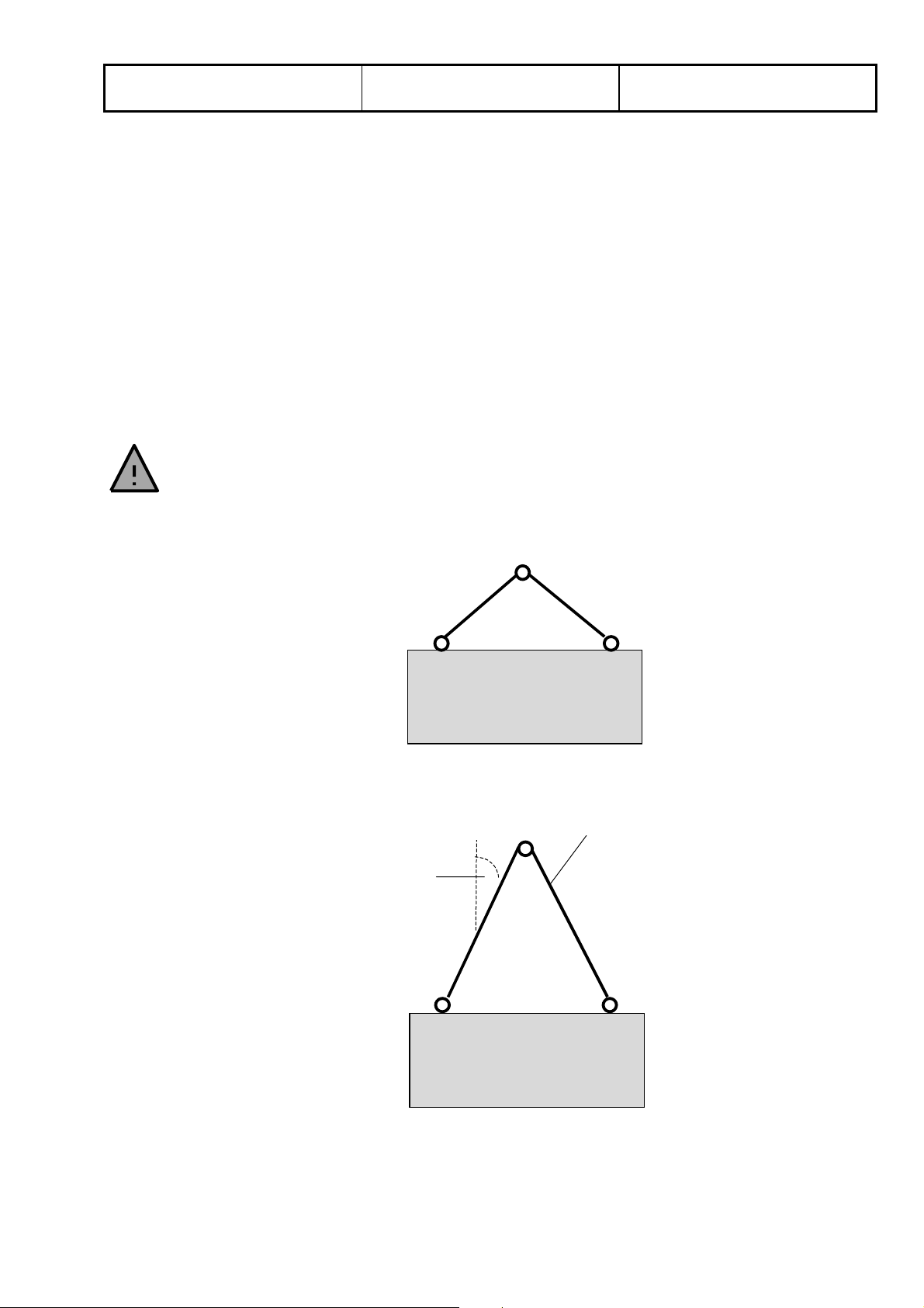
Allow for the weight given in the Operating Instructions when transporting the
plant.
Use a forklift or crane with carrying ropes/cables of the right strength.
2.3 Transport carefully
Wrong:
Right:
30°
≤
Carrying rope/wire
Page 6
Polo Filter-Technik Bremen
Drafted by: M. Schwarzer Stand: 01.05
Operating Instructions
General Notes
BEMO_01E/7
Page 6 of 6
3. Safety identification on the filter plant
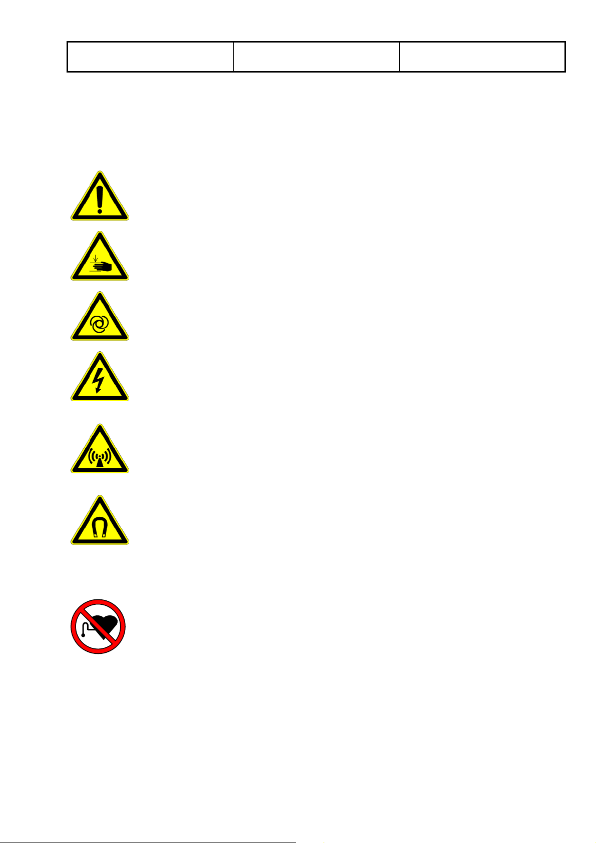
Safety instructions, in the shape of pictograms, have been attached to the filter plant in a number of places. In
order to avoid danger to operating personnel or third parties, these instructions must be followed!
3.1 Warning signs (black with yellow background)
Warning of a dangerous position (general)
Warning of the danger of injury to the hands (e.g. cutting, crushing ...)
Warning of the automatic starting up of the mashine
Warning of dangerous electrical voltage
Warning of electromagnetic fields
Warning of manetic fields
3.2 Prohibition sign (red)
Prohibited for persons with heart pacemakers
Page 7

Polo Filter-Technik Bremen
Drafted by: M. Schwarzer Issue: 03.08
Operating instructions for
Slope Bed Filter SB
BEMO_09E/6
Page 1 of 8
1. Technical data:
1.1 Machine details (information shown on filter type plate)
Please enter the information shown on the filter type plate in the following table. In the event that problems
should require remedying, this information can help in avoiding unnecessary delays.
Type
Order No.
Further information relating to your filter (max. flow rate, weight etc.) is to be found in the table in the
accompanying brochure.
1.2 Correct use of the filter unit
The equipment is exclusively designed for separating liquids, the composition of which is defined in the order
confirmation. Use of the equipment for filtering other substances is prohibited. Incorrect use of the equipment
can jeopardise the life and limb of the user and/or that of third parties or can prevent efficient operation of the
equipment.
2. Setting up and starting up
When working on the system, please take note of the danger and safety instructions attached to the filter. In
order to avoid any damage to the filter aid, it must be covered during assembly (e.g. by a welding blanket).
2.1 Installation
2.1.1 Filter installation (if supplied without tank)
If you have obtained a filter without the accompanying tank you must erect the filter above the existing collecting
trough. Beforehand it is to be ensured that the mounting unit is able to take the weight of the filter plus the
weight of the medium to be filtered. During installation care is to be taken that the filter is completely flush and
level and unable to slip.
2.1.2 Installation (if supplied with tank)
Position the filter, with the collecting trough beneath, in the intended position. Care is to be taken that the
equipment is level and firmly seated.
The equipment must be level in order to ensure that the medium to be filtered is evenly distributed over the filter
fabric.
Page 8
Polo Filter-Technik Bremen
Drafted by: M. Schwarzer Issue: 03.08
Operating instructions for
Slope Bed Filter SB
BEMO_09E/6
Page 2 of 8
2.2 Connecting the equipment
Install the return channel plus the machine supply line. If the filter is to be fed using a pump, pipes of suitable
diameter have to be used in order to lower the speed of the liquid reaching the intake distributor to a minimum.
The pipes and connector channels to the machine to be supplied have to have a certain rate of fall so that the
liquid flows quickly and leaves no deposits. The use of bends should be avoided.
If rubber or plastic pipes are used, their length is to be precisely calculated in order to avoid air pockets in which
deposits would certainly form, eventually blocking the pipes.
2.3 Electrical connection
The filter equipment comes ready to be connected and must simply be connected to the machine as per
enclosed wiring diagram.
Once connection work is completed, the entire electrical installation must be checked as per VDE (Association
of German Electrical Engineers). If connection has not been carried out professionally, no claims will be
accepted under warranty.
2.4 Starting up the plant
Please check whether the filter aid is positioned correctly and has not been damaged. If this is the case, the
plant can be filled. Please check continuously that all connecting pipes do not leak.
When filling up for the first time, please note the max. fill level of the tank. Details are listed in the construction
plans. When filling the tank at a later date, the liquid still in the system must be taken into consideration to avoid
the system overflowing.
If the filter system has been equipped with a switching cabinet, the main switch must be operated and the
control voltage must be switched to “ON“ when starting it up for the first time. Other necessary details are listed
in the enclosed electrical plans.
All control devices (float switches) have been pre-set and checked at the factory. However, during the starting
up process, the operator must observe all functions and if necessary correct them.
All pumps must be equipped with sliders and pressure gauges. They must be set in accordance with the points
specified in the constructions plans. After these points have been reached, fully automatic operation
commences. If there are no leaks, the plant is operational.
3. Inspection and maintenance work
Caution! Equipment starts up automatically!
Prior to carrying out any work on the equipment, switch to neutral and stop
conveyance of impure medium!
Caution! Some types of impurities and some types of
impure media can cause injury (e.g. cuts or burns).
Therefore it is necessary to wear suitable protective clothing!
Page 9
Polo Filter-Technik Bremen
Drafted by: M. Schwarzer Issue: 03.08
Operating instructions for
Slope Bed Filter SB
BEMO_09E/6
Page 3 of 8
3.1 Filter fleece
We have equipped this filter with fleece type ________.
)
However, we can also supply approximately 20 other fleece qualities from stock.
Depending on the version being used, fleece consumption is monitored using a fleece limit switch with a visual
or acoustic alarm or must be monitored by means of regular sight checks.
Care is to be taken that the equipment is never operated without the use of a filter
)
fleece.
When the roll of fleece is almost used up it must be replaced.
Caution! Sudden start-up of conveyor chain may result in injury!
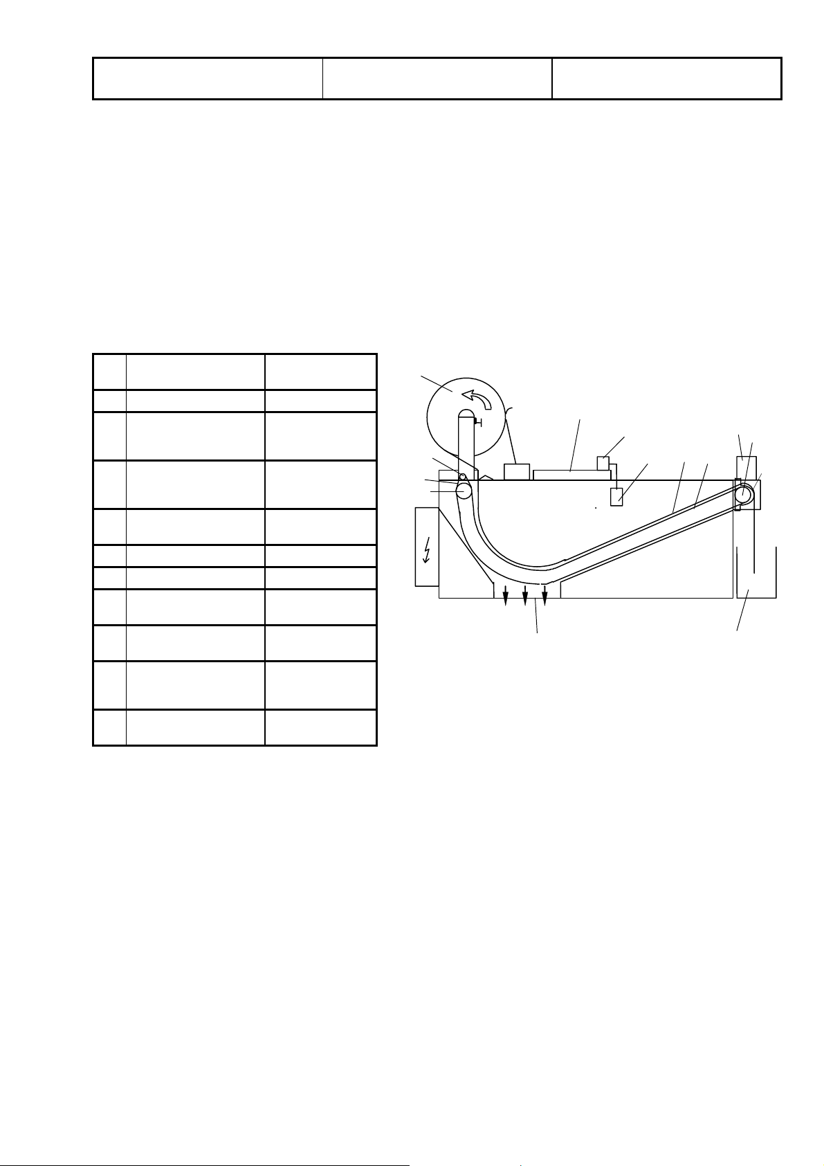
Fig. 3.1 shows how the fleece roll is being changed.
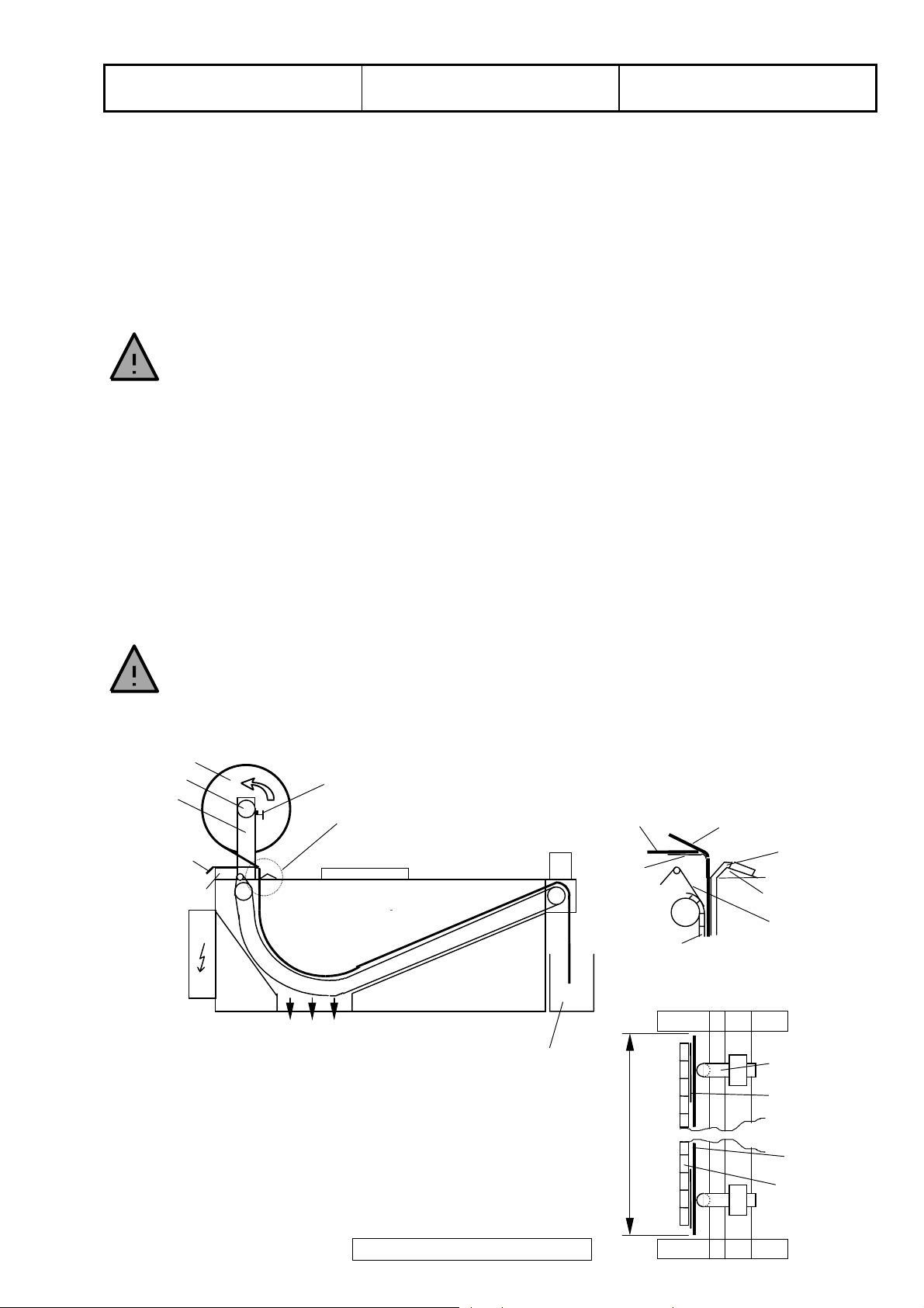
First, loosen the clamps (1) on either side of the fleece roll holder (2), take out the plastic tube (3) and remove
the cardboard tube from the old fleeceroll. Then push the plastic tube in the new fleece roll (4) and position in
the fleece roll holder.
Care must be taken to make sure that the direction of fleece rotation is correct.
)
(see Fig. 3.1)!
The direction of rotation of the fleece roll must be changed in the case of fleeces
)
with defined dirt and clean sides (Types 380/400/480)!
Centre the fleece roll and secure from moving by tightening the clamps. Some play is necessary so that the
fleece roll can turn properly.
Place the new fleece over the rest of the old roll and direct it down into the gap between the cover (5) and the
angle (6).
NEVER touch the chain!
Danger of injury!
Lift the float in order to trigger the band transport and to transport the fleece untill the old fleece cannot be seen
anymore (approx. 500 mm).
4
3
2
old fleece
(approx. 500mm)
5
1
A
old
fleece
5
conveyor
Detail A
new fleece
side gasket
(firm)
6
rotating seal
View from above:
dirt box
Fig. 3.1 Replacing the fleece roll
side gasket
(firm)
rotating seal
fleece
width of fleece
conveyor
chain
Page 10
Polo Filter-Technik Bremen
Drafted by: M. Schwarzer Issue: 03.08
Operating instructions for
Slope Bed Filter SB
BEMO_09E/6
Page 4 of 8
3.2 Dirt box
The dirt box ought to be regularly checked.
Do not allow too much used fleece to build up in the dirt box!
)
Otherwise there is a danger of the used fleece becoming wedged in the (returning) conveyor chain.
3.3 Side gasket (PTFE-tube with core)
The condition of the side gasket must be checked every 2 months and the gasket replaced if necessary.
Caution: soiled medium may enter the clean tank if the side gasket is damaged!
)
Before replacing the gasket the filter must be emptied by cycling the filter mat forward, and the intake of new
medium must be interrupted.
After emptying, unscrew the collar band and advance the side gasket to the discharge side by cycling the filter.
The PTFE tube is threaded with its open side into the vee-guide between the cover and the angle at the filter
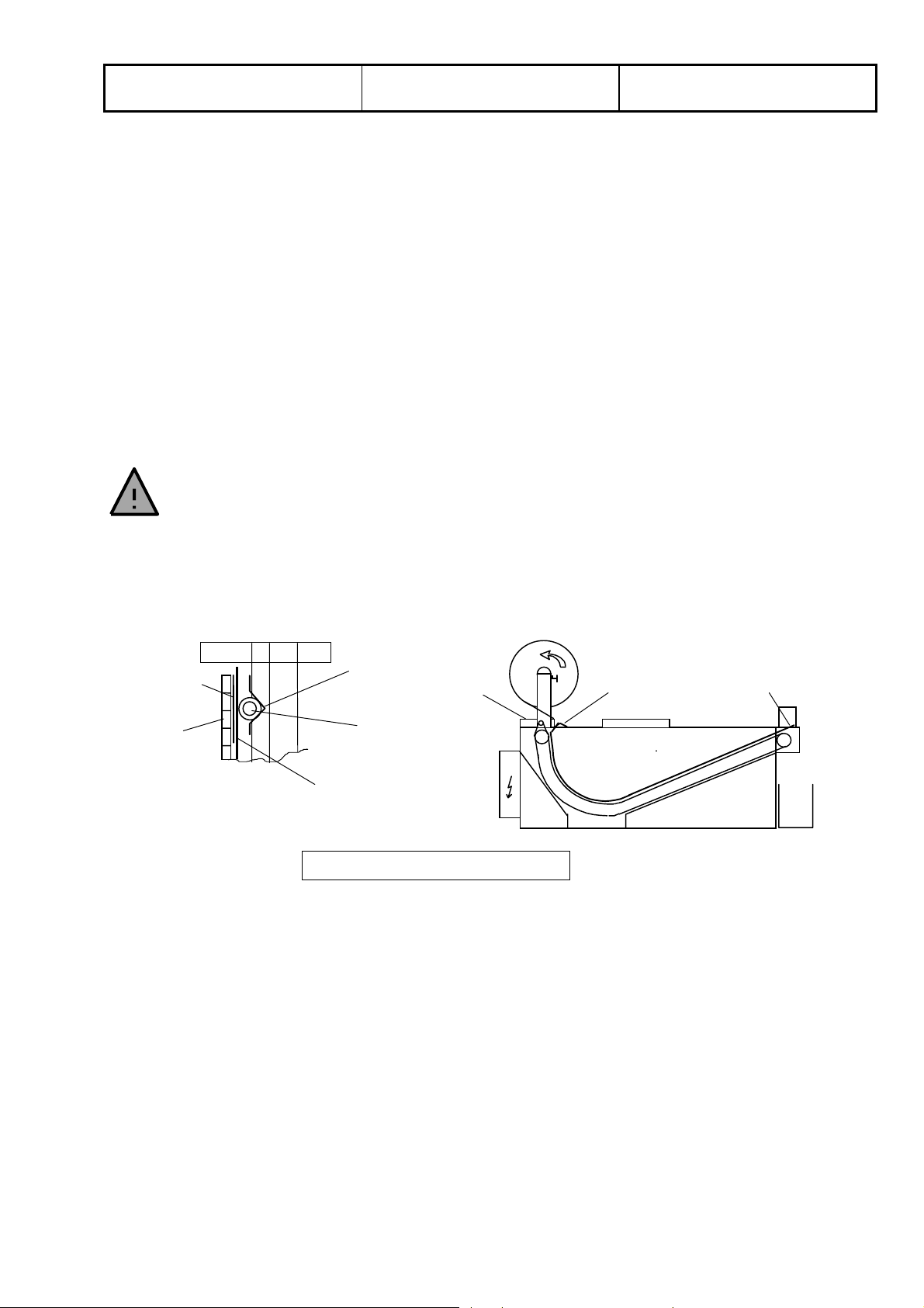
fabric intake side (see fig. 3.2). By lifting the float switch the belt cycle is triggered and the gasket is fed through.
NEVER touch the chain!
Danger of injury!
After feeding through the gasket, it is left hanging loose at the discharge side. On the feed side, the gasket must
be bent around the angle edge and fixed with the collar band. Please ensure that the metal pin is located
underneath the collar band.
Make screw
connection with
clamping ring
here
Let it hang loose
here
Undergasket
Conveyor
chain
Veeguide
Cover
Side gasket
Fleec e
Fig. 3.2 Replacing the side gasket
Page 11
Polo Filter-Technik Bremen
Drafted by: M. Schwarzer Issue: 03.08
Operating instructions for
Slope Bed Filter SB
BEMO_09E/6
Page 5 of 8
3.4 Undergasket (rotary)
If the filter mat is damaged during operation of the filter it may be possible that the undergasket is damaged. In
this case it must be replaced.
To do this, first interrupt the intake of new medium and empty the filter. Then remove the filter mat from the
filter. Unscrew the cover on the feed side. Trigger the belt cycle until the connection pin at the front of the filter is
visible.
NEVER touch the chain!
Danger of injury!
Pull out the pin and, using the belt cycle, feed the undergasket out of the filter.
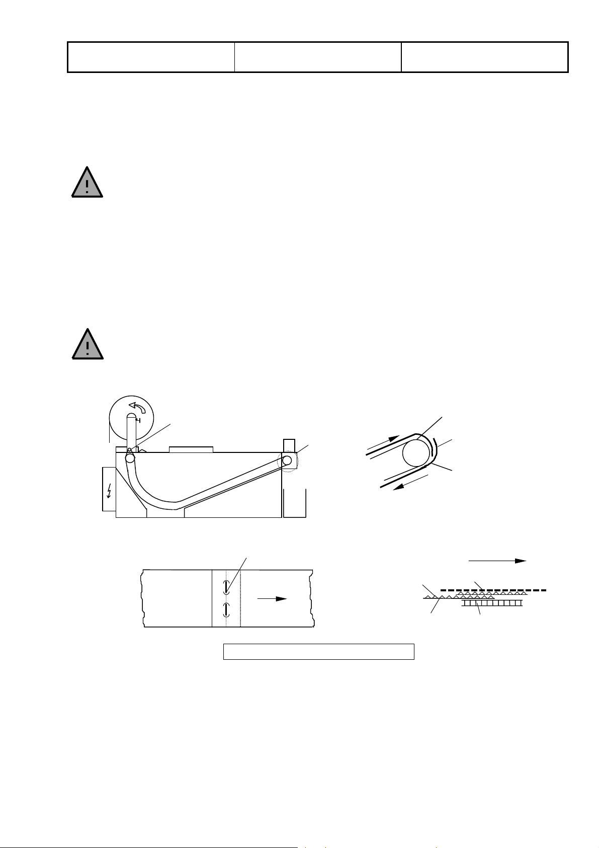
When fitting the new gasket, care must be taken to place the smooth side towards the transport chain (see fig.
3.3).
Connect the gasket to the transport chain on the discharge side and feed to the back by triggering the belt
cycle. There, remove the gasket from the chain, feed it around the deflection roller and into the gap between the
transport chain and the PTFE tube. Trigger the belt cycle and feed the gasket through to the front side.
Connect both ends with the pin. Take care to ensure that the upper end is located at the back (see detail A in
fig. 3.3).
The connection pin must be inserted such that the ends are et the smooth side.
)
Wear suitable protection (gloves) when fitting the pin to prevent stab injuries.
After replacing both undergaskets the cover must be put back in place. Then the fleece can be put on as
described at 3.1. However, the belt needs to be cycled to the discharge side.
Detail A
deflection
shaft
View from above:
connection pin
(ends at bottom)
direction of
feed
A
rough side
smooth side
conveyor chain
connect with
pin here
undergasket
direction of
feed
fleece
conveyor
chain
Fig. 3.3 Connecting the undergasket
3.5 Fleece limit switch
If the equipment is fitted with a fleece limit switch then its function must be checked during fleece roller changes
in order to ensure that the equipment is not accidentally operated without the filter fleece. Furthermore it is to be
ensured that the switch is not mechanically damaged (e.g. bent), which could alter the switching points.
Page 12
Polo Filter-Technik Bremen
Drafted by: M. Schwarzer Issue: 03.08
Operating instructions for
Slope Bed Filter SB
BEMO_09E/6
Page 6 of 8
3.6 Float switch
All POLO-Filter-Technik GmbH float switches are mechanical, buoyancy-dependent control elements. Adhering
particles of dirt are capable of altering the switching points and must therefore be dealt with promptly. This is an
inspection which must to be carried out at least once per week.
If the float switch does not function correctly, the filter unit may overflow.
)
3.7 Greasing
This special design of this filter makes greasing unnecessary.
3.8 Transport chain
The tension of the transport chain must be checked once a month. As the chain is self-tensioning, there is no
chain adjuster. This transport chain balances any play under tension. If the chain no longer transports correctly
(chain jumps), it must be shortened or possibly be replaced.
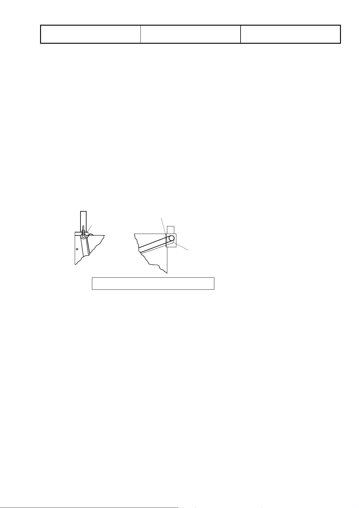
Type SB-B1.6 is an exception. With this type the chain tension must be set by means of 2 tension jacks located
at the deflection shaft of the conveyor chain. Normally the contact angle of the drife shaft is nearly 180°. If it is
fallen down to 100-110°, the chain must be re-tensioned with the chain tensiners at the deflection shaft
(see fig. 3.4).
chain tension
correct
chain tensioner
chain too long
Î
re-tension
Fig.3.4 Adjusting transport chain tension
3.9 Additional maintenance
If your filter plant is equipped with additional components (e.g. magnetic filters, belt skimmer, hasp...) please
refer to the respective chapters of these operating instructions on how to perform additional maintenance work.
The manufacturer’s regulations apply to all pumps and drives. More details are listed in the enclosed data
sheets and documentation.
Page 13

Polo Filter-Technik Bremen
Drafted by: M. Schwarzer Issue: 03.08
Operating instructions for
Slope Bed Filter SB
BEMO_09E/6
Page 7 of 8
4. Identifying and remedying faults
4.1 General
Quick fault analysis can be carried out using the following list. When faults occur, the user is usually able to deal
with them himself. If this should not prove possible, the probable cause of the fault can be identified over the
telephone, using this fault analysis.
The equipment may only be repaired by competent personnel. In the event of
)
problems with the equipment please contact the manufacturer.
Because of irregular dirt concentration, the filter may be overloaded for short periods of time.
As a result of this:
• The level of liquid continues to rise
• An overflow alarm is triggered
• The belt cycle is continuous
This state is NOT NORMAL! If the plant does not correct itself within a very short period of time, you must find
the cause.
4.2 No or insufficient filtration
Visible faults:
• Filter fleece roll has been used up, continuous belt is worn
• Indicator light (if installed) reports end of fleece
Rectifying fault:
• Renew filter aid as described in items 3.1
4.3 Overflow
Visible problem:
• Medium flows over filter edge
Remedy:
check:
• that the float switch is functioning and has no deposits
• the chain drive motor safety switch
• that the conveyor chain moves freely
• any external fuses
• the inflow rate
4.4 Filter band constantly slips
Visible problem:
• The equipment advances without medium flowing onto the filter
Remedy:
• Check that the float switch is functioning and free of deposits
4.5 Pumps
Visible problem:
• Noises, low pressure
Remedy:
• Check direction of rotation. - Close the valve
- If max. pressure isn't achived, change direction of rotation by changing the
phase.
- If max. pressure isn't achived now, the pump is out of order
Page 14
Polo Filter-Technik Bremen
y
y
y
y
Drafted by: M. Schwarzer Issue: 03.08
Operating instructions for
Slope Bed Filter SB
BEMO_09E/6
Page 8 of 8
4.6 Customer service
In the event of queries our customer services department is naturally ready to help, and can be reached on:
0049 (0)421 / 23 80 2-0
In order to avoid unnecessary delays, always have the technical data relating to your equipment to hand when
making your call.
During the warranty period, only POLO service engineers or persons working on
behalf of POLO may carry out repairs or make modifications. Otherwise no claims
)
will be accepted under the warranty.
4.7 Spare parts
When ordering spare parts please quote the order number stated on the type plate.
1 Drive shaft for
conve
2 drive motor spare part
3 conveyor chain
4 side gasket
5 float switch complete spare part
6 float single spare part
7 fleece roll Floor stock item
8 Deflection shaft for
conve
9 rotating seal
10 Deflection shaft for
rotating seal
11 Bearing spare part
or chain
or chain
spare part
Wear and tear
part (approx. 2
ears)
Wear and tear
part (approx. 2
ears)
spare part
Wear and tear
part (approx. 2
spare part
7
inlet
3
dirt box
2
1
11
9
10
5
4
6
8
outlet
Page 15

Exakte Trennung
Rein-/Schmutzwasser
Für extrem dünne
Vliese geeignet,
weil es getragen und
ht gezogen wird
nic
Hoher Flüssigkeitsspiegel
begrenzt den Vliesverbrauch
FILTERANLAGEN NACH MASS
Für Öl, Wasser, Emulsion
und andere flüssige Medien
Schrägbettfilter SB
Der POLO Schrägbettfilter SB ist ein vollautomatisch arbeitender Filter für
die Reinigung vieler, unterschiedlicher Flüssigkeiten.
Er besteht aus einem Stahl- oder Niro- geschweißtem Gehäuse mit Antriebsund Umlenkwelle. Die endlose, das Filtervlies tragende Transportkette bildet
eine extrem tiefe Filtermulde. Der Vortrieb erfolgt über einen Getriebemotor.
Die Steuerungsfunktionen, ausgelöst von Schwimmerschaltern, werden von
einem externen oder integriertem El.-Schaltkasten ausgeführt.
Individuelle Problemlösungen
Page 16
Schrägbettfilter SB
FFuunnkkttiioonneenn
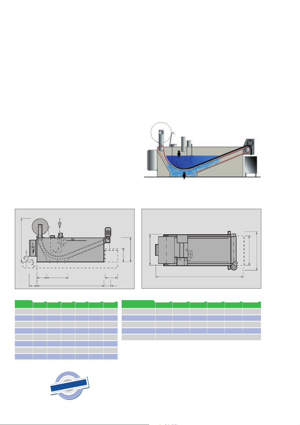
Die Flüssigkeit wird dem Filter über den Einlaufverteiler
drucklos zugeführt, durchfließt das Vlies und gelangt
gereinigt über den Auslauf in einen darunter stehenden
Reintank.
Durch die kurzen Bandtakte wird nur ein sehr kleiner Teil
der Filterfläche erneuert, so dass der wesentliche Teil der
Flüssigkeit dieses “Anschwemmittel” durchfließt und
damit die Filterfeinheit erhöht.
Die Form des Filterbettes ermöglicht einen hohen Flüssigkeitsspiegel. Dadurch wird der Mengendurchsatz gesteigert und das Vlies optimal genutzt. Auf dem Vlies lagern
sich die Schmutzpartikel ab und vermindern mehr und
mehr den Durchfluss.
Diese Schmutzpartikel (Filterkuchen) stellen eine zusätzliche, hochwertige Filterschicht dar und verbessern damit
das Filterergebnis. Der Spiegel steigt auf der Schmutzseite des Filters. Bei einem voreingestellten Niveau
erfolgt ein Bandtakt (ca. 50 mm lang).
Der Filterprozess wird während des Weitertaktens nicht
unterbrochen, ein zusätzlicher Puffertank ist nicht notwendig! Der aufgebaute Filterkuchen ist ein wertvolles
Filterhilfsmittel und verbessert den Reinheitsgrad maßgeblich.
Filtervlies
Einlauf
Eine Schlauchdichtung, beständig gegen alle handelsüblichen Kühlschmierstoffe, trennt die Schmutzkammer
gegen die Reinseite zuverlässig ab.
Ein Vliesenderollentaster (Option) gibt ein Signal, dass
die Vliesrolle ersetzt werden muß.
Filtervlies
Einlauf-
Schaltkasten
verteiler
Schwimmerschalter
Auslauf
Filterkuchen
Antrieb
H
Schalt- oder
FFiilltteerr TTyypp
L
B
H
L1
L2
B1
B2
B3
Klemmkasten
SSBB --AA0033
1280
735
800
882
397
571
440
560
Tank
L2 x B2 250180
Auslauf
in Reintank
SSBB --AA0044
SSBB --AA0088
1660
2660
735
793
800
800
1250
2250
397
13 97
571
571
440
265
560
560
b
e
i
n
r
t
a
e
c
b
h
h
c
a
F
DIN EN ISO 9001
H
§
W
1
9
I
L1150 125
SSBB --BB0088
SSBB --BB11..66
1660
2660
1250
1250
800
800
1250
2250
397
13 97
108 4
108 4
954
1060
718
1060
POLO Filter-Technik Bremen GmbH
FILTERANLAGEN NACH MASS
Für Öl, Wasser, Emulsion
G
und andere flüssige Medien
Schmutz-
kasten
SSBB --CC22..44
2760
176 6
1000
2250
1396
1618
112 4
1560
Abwurf
440
250
FFiilltteerr TTyypp
Gewicht ca.
Inhalt ca.
Durchlaufleistung max.
Anschlusswerte L1
Versorgungsspannung
Werkstoffe: Stahl oder VA
Anstrich RAL 6011 (Sonderlackierung möglich)
B1
Filtervlies
SSBB--AA0033
90 kg
170 l/min
0,09 kW
.
.
.
40 l
Schwimmer-
schalter
L
SSBB --AA0044
120 kg
220 l/min
0,09 kW
100 l
SSBB --AA0088
180 kg
250 l
400 l/min
0,12 kW
400 V 50Hz
SSBB --BB0088
220 kg
440 l/min
0,12 kW
Technische Änderungen vorbehalten.
200 l
SSBB --BB11..66
320 kg
420 l
800 l/min
0,12 kW
In den Ellern 6 | 28832 Achim
Telefon 0421 238 02-0 | Fax 23802-99
[email protected] | www.polo-filter.com
B
B3
SSBB --CC22..44
750 kg
700 l
1200 l/min
0,37 kW
ONPR-09/04
Page 17

Polo Filter-Technik Bremen
GmbH
Übersetzung Prospekt SB
englisch
ONPR-09E/2
Seite 1 von 2
POLO Slope Bed Filter SB
Positive separation of upper and lower chamber by unique rotating hose seal.
Suitable for extremely thin vleece.
Very high liquid level helps reuce vleece consumption.
Application
Polo slope bed filters clean machine tool collants fully automatic. Tank contains drive and return shaft
Attached to a steel frame. The endless transport chain, which carries the vleece, forms a very deep filter
base. Advance of vleece is controlled by float switch and drive motor. Unit can be supplied with terminalor control box.
Function
Dirty liquid is lead into the filter without pressure by gravity or with a pump. The liquid flows through the vleece
and returns clean through the outlow into the clean below.
The configurar´tion of the filter bed allows for a high liquid level. This generates higher volume and optimal use
of
veece . Dirt particles deopsit on the filter vleece, liquid level rises to a preset trigger which then activates vleece
advance. Clogged vleece is pulled out and clean vleece pulled in. A hose seal, resistant against all coolants
reliably seperates the dirt-from chamber.
Maintenance
The use and replacement of the filter vleece needs to be watched unless an optional alert is built into the syste
system. The fleece roll can be replaced without interruption of normal operations.
--------------------------------------------------------------------------------------------------------------------------------------------------Abwurf = dumping
Ausführung als Rückpumpstation = execution as return-line pump station
Auslauf in Reintank = outlet into cleantank
Durchlaufleistung = capacity max.
Einlauf = inlet
Filter, Typ = filter, type
Filtervlies = filter fleece
Gewicht = weight approx;
Schalt- oder Klemmenkasten = switch box / terminal block
Schmutzkasten = dirt box
Schwimmerschalter = floating switch
Page 18

Polo Filter-Technik Bremen
GmbH
Zubehör Schmutzkasten = accessories dirt box
Übersetzung Prospekt SB
englisch
ONPR-09E/2
Seite 2 von 2
Page 19
Page 20
CRK, CHK, SPK, MTH, MTR
Installation and operating instructions
Montage- und Betriebsanleitung
Notice d’installation et d’entretien
Istruzioni di installazione e funzionamento
Instrucciones de instalación y funcionamiento
Instruções de instalação e funcionamento
ВЕБ½ГРГБИ¿ТºСТ¿СЕРИ¿ЗЙГЗТНУПБ½¿Р
Installatie- en bedieningsinstructies
Monterings- och driftsinstruktion
Asennus- ja käyttöohjeet
Monterings- og driftsinstruktion
TM02 1571 1401
Page 21

We GRUNDFOS declare under our sole r esponsibility tha t the products
CRK, CHK, SPK, MTH and MTR, to which this declaration relates, are
in conformity with the Council Directives on the approximation of the
laws of the EEC Member States relating to
– Machinery (98/37/EEC).
Standard used: EN 292.
– Electromagnetic comp atibility (89/336/ EEC).
Standards used: EN 50 081-1 and EN 50 082-2.
– Electrical equipment designed for use within certain voltage limits
(73/23/EEC).
Standards used: EN 60 335-1 and EN 60 335-2-51.
Nous GRUNDFOS déclarons sous notre seule responsabilité que les
produits CRK, CHK, SPK, MTH et MTR auxquels se réfère cette décla-
ration sont conformes aux Directives du Conseil concernant le
rapprochement des législations des Etats membres CEE relatives à
– Machines (98/37/CEE).
Standard utilisé: EN 292.
– Compatibilité électromagnétique (89/336/CEE).
Standards utilisés: EN 50 081-1 et EN 50 082-2.
– Matériel électrique destiné à employer dans certaines limites de
tension (73/23/CEE).
Standards utilisés: EN 60 335-1 et EN 60 335-2-51.
Nosotros GRUNDFOS decla ramos bajo nuestra única responsabilidad
que los productos CRK, CHK, SPK, MTH yMTR a los cuales se refiere
esta declaración son conformes con las Directivas del Consejo relativas a la aproximación de las legislac iones de los Es tados Miembros de
la CEE sobre
– Máquinas (98/37/CEE).
Norma aplicada: EN 292.
– Compatibilidad electromagnética (89/336/CEE).
Normas aplicadas: EN 50 081-1 y EN 50 082-2.
– Material eléctrico destinado a utilizarse con determinadas límites
de tensión (73/23/CEE).
Normas aplicadas: EN 60 335-1 y EN 60 335-2-51.
¢É¼ÏÄ+692(*37БДИЫКМТЙВЙВ¾НМЗИВЖРСЖЗ¹БЖЗ»Й¾ПВТЕЪКД
ЩСЖС¾НОМЖЩКС¾'6/',/74/18,З¾ Ж186РТЙЙМОУЫКМКС¾Ж
ЙВСДК¬БДА¼¾СМТ°ТЙ¿МТИ¼МТВН¼СДПРЪАЗИЖРДПСЦККЩЙЦКСЦК
§О¾СЫК0ВИЫКСДП¢ТОЦН¾ЖЗ»П¢КЦРДПРВРФºРДЙВС¾
v ©ÄԾʻɾѾ((&
ОЩСТНМНМТФОДРЖЙМНМЖ»ЕДЗВ(1
v ¤ИВЗСОМЙ¾АКДСЖЗ»РТЙ¿¾СЩСДС¾((&
ОЩСТН¾НМТФОДРЖЙМНМЖ»ЕДЗ¾К(1З¾Ж(1
v ¤ИВЗСОЖЗºПРТРЗВТºПРФВБЖ¾РЙºКВПАЖ¹ФО»РДВКСЩПМОЖРЙºКЦК
МО¼ЦКДИВЗСОЖЗ»ПС¹РДП((&
ОЩСТН¾НМТФОДРЖЙМНМЖ»ЕДЗ¾К(1З¾Ж
(1
Vi GRUNDFOS försäkrar under ansvar, att produkterna CRK, CHK,
SPK, MTH och MTR, som omfattas av denna försäkran, är i överens-
stämmelse med Rådets Direktiv om inbördes närmande till EUmedlemsstaternas lagstiftning, avseende
– Maskinell utrustning (98/37/EC).
Använd standard: EN 292.
– Elektromagnetisk kompatibilitet (89/336/EC).
Använda standarder: EN 50 081-1 och EN 50 082-2.
– Elektrisk material avsedd för användning inom vissa spännings-
gränser (73/23/EC).
Använda standarder: EN 60 335-1 och EN 60 335-2-51.
Vi GRUNDFOS erklærer under ansvar, at produkterne CRK, CHK,
SPK, MTH og MTR, som denne erklæring omhandler, er i overens-
stemmelse med Rådets direktiver om indbyrdes tilnærmelse til EF
medlemsstaternes lovgivning om
– Maskiner (98/37/EØF).
Anvendt standard: EN 292.
– Elektromagnetisk kompatibilitet (89/336/EØF).
Anvendte standarder: EN 50 081-1 og EN 50 082-2.
– Elektrisk materiel bestemt til anvendelse inden for visse
spændingsgrænser (73/23/EØF ).
Anvendte standarder: EN 60 335-1 og EN 60 335-2-51.
Declaration of Conformity
Déclaration de Conformité
Declaración de Conformidad
¢¼ЙЧСЕ±УККЪПФЧСЕР
Försäkran om överensstämmelse
Overensstemmelseserklæring
Wir GRUNDFOS erklären in alleiniger Verantwortung, daß die Produkte CRK, CHK, SPK, MTH und MTR, auf die sich diese Erklärung
bezieht, mit den folgenden Richtlinien des Rates zur Angleichung der
Rechtsvorschriften der EG-Mitgliedstaaten übereinstimmen:
– Maschinen (98/37/EWG).
Norm, die verwendet wurde: EN 292.
– Elektromagnetische Verträglichkeit (89/336/EWG).
Normen, die verwendet wurden: EN 50 081-1 und EN 50 082-2.
– Elektrische Betriebsmittel zur Verwendung innerhalb bestimmter
Spannungsgrenzen (73/23/EWG).
Normen, die verwendet wurden: EN 60 335-1 und EN 60 335-2-51.
Noi GRUNDFOS dichiariamo sotto la nostra esclusiva res ponsa bilità
che i prodotti CRK, CHK, SPK, MTH e MTR ai quali questa dichiarazione se riferisce sono conformi alle Direttive del Consiglio
concernente il ravvicinamento delle legislazioni degli Stati membri
CEE relative a
– Macchine (98/37/CEE).
Standard usato: EN 292.
– Compatibilità elettromagnetica (89/336/CEE).
Standard usati: EN 50 081-1 e EN 50 082-2.
– Materiale elettrico destinato ad essere utilizzato entro certi limiti di
tensione (73/23/CEE).
Standard usati: EN 60 335-1 e EN 60 335-2-51.
Nós GRUNDFOS declaramos sob nossa única responsabilidade que
os produtos CRK, CHK, SPK, MTH e MTR aos qua is s e re fere e sta
declaração estão em conformidade com as D irectivas do Con selho das
Comunidades Europeias relativas à aproximação das legislações dos
Estados Membros respe itant es à
– Máquinas (98/37/CEE).
Norma utilizada: EN 292.
– Compatibilidade electromagnética (89/336/CEE).
Normas utilizadas: EN 50 081-1 e EN 50 0 82-2.
– Material eléctrico destinado a ser utilizado dentro de cer t os li mites
de tensão (73/23/CEE).
Normas utilizadas: EN 60 335-1 e EN 60 3 35-2- 51.
Wij GRUNDFOS verklaren geheel onder eigen verantwoordelijkheid
dat de produkten CRK, CHK, SPK, MTH en MTR waarop deze verklaring betrekking heeft in overeenstemming zijn met de Richtlijnen van
de Raad inzake de onderlinge aanpassing van de wet gevingen v an de
Lid-Staten betreffende
– Machines (98/37/EEG).
Norm: EN 292.
– Elektromagnetische compatibiliteit (89/336/EEG).
Normen: EN 50 081-1 en EN 50 082-2.
– Elektrisch materiaal bestemd voor gebruik binnen bepaalde
spanningsgrenzen ( 73/ 23 /EEG ).
Normen: EN 60 335-1 en EN 60 335-2-51.
Me GRUNDFOS vakuutamme yksin vastuullisesti, että tuot teet CRK,
CHK, SPK, MTH ja MTR, jota tämä vakuutus koskee, noud atta vat
direktiivejä jotka käsittelevät EY:n jäsenvaltioiden koneelli sia laitte ita
koskevien lakien yhdenmukaisuutta seur.:
– Koneet (98/37/EY ).
Käytetty standardi: EN 292.
– Elektromagneettinen vastaavuus (89/336/EY).
Käytetyt standardit: EN 50 081-1 ja EN 50 082-2.
– Määrättyjen jänniterajoitusten puitteissa käytettävät sähköiset
laitteet (73/23/EY).
Käytetyt standardit: EN 60 335-1 ja EN 60 335-2-51.
Bjerringbro, 1st April 2001
Konformitätserklärung
Dichiarazione di Conformità
'HFODUDomRGH&RQIRUPLGDG H
Overeenkomstigheidsverklaring
Vastaavuusvakuutus
Jan Strandgaard
Technical Manager
Page 22
CONTENTS
Page
1. Applications 4
2. Type designation 4
2.1 Pump key for CRK, CHK, SPK and MTH 4
2.2 Pump key for MTR 4
3. Technical data 4
4. Installation 4
4.1 Pump location 5
4.2 Suction conditions 5
5. Electrical connection 6
6. Operation and maintenance 6
6.1 Lubrication and maintenance 6
6.2 Filters 6
6.3 Periodic checks 7
7. Service 7
8. Sound pressure level 7
9. Fault finding chart 8
10. Disposal 8
Before beginning installation procedures,
these installation and operating instructions should be studied carefully. The installation and operation should also be in
accordance with local regulations and accepted codes of good practice.
1. Applications
The GRUNDFOS pumps, types CRK, CHK, SPK,
MTH and MTR, are multistage centrifugal pumps designed for pumping liquids for machine tools, condensate transfer, liquid transfer in industrial washing
machines and similar applications.
The pump must not be used for the transfer of inflammable liquids such as diesel
oil, petrol or similar liquids.
The pumps are designed for pumping liquids with a
density and viscosity corresponding to those of water. The pumped liquid must not contain abrasive
particles or fibres.
When pumping liquids with a density or viscosity
higher than that of water, the motor size should be
taken into consideration.
2. Type designation
The standard range of pumps encompasses complete impeller in chamber combinations. On request,
other lengths, against duty combinations, can be
supplied by fitting empty intermediate chambers instead of standard chambers with impellers.
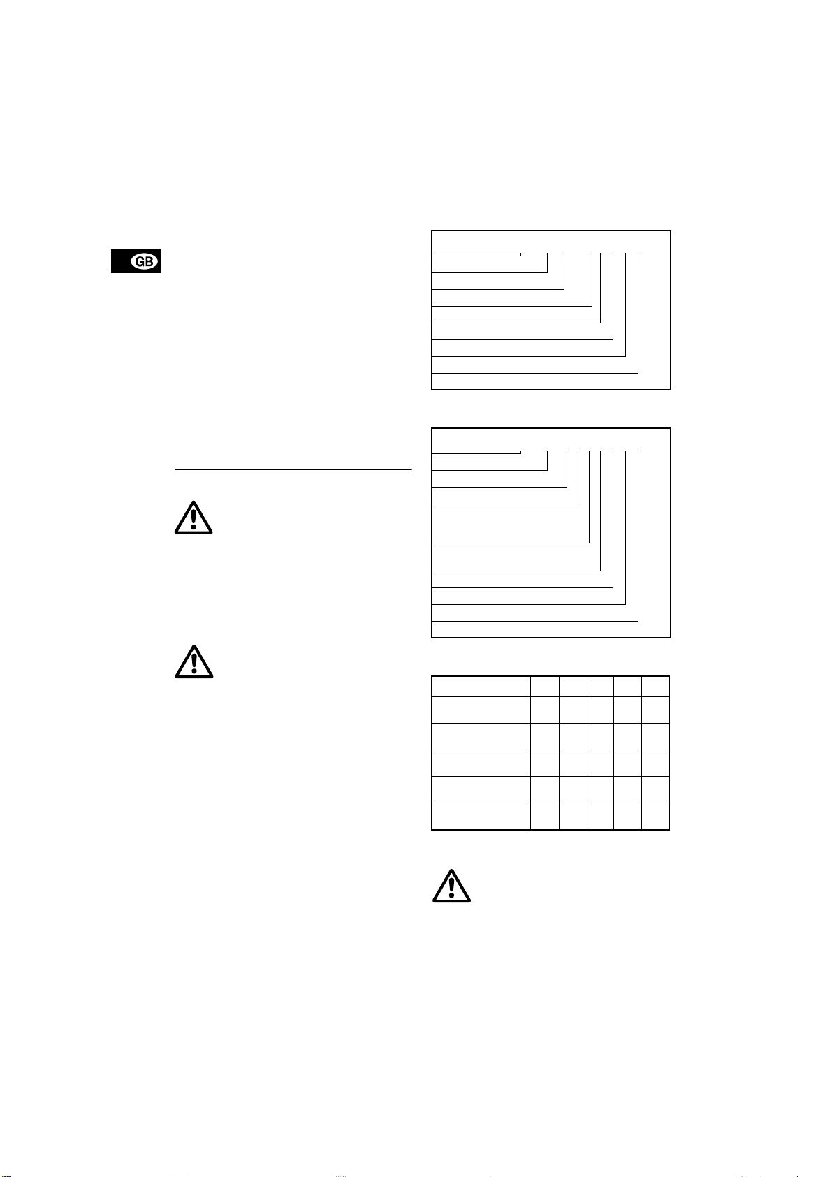
The pump key on the pump nameplate indicates the
number of chambers and impellers fitted to the
pump.
2.1 Pump key for CRK, CHK, SPK and MTH
Example CRK 4 - 160 / 2 -x -x -x -xxxx
Pump range
Nominal flow rate in m³/h
Number of stages x 10 (SPK x 1)
Number of impellers
Code for pump version
Code for pipework connection
Code for materials
Code for shaft seal and rubber pump parts
2.2 Pump key for MTR
Example MTR 32- 2 /1 -1 -x -x -x -xxxx
Pump range
Nominal flow rate in m³/h
Number of stages
Number of impellers (is only used
if the pump has fewer impellers
than chambers)
Number of impellers with reduced
diameter
Code for pump version
Code for pipework connection
Code for materials
Code for shaft seal
3. Technical data
CRK CHK SPK MTH MTR
Minimum liquid
temperature [°C]
Maximum liquid
temperature [°C]
Maximum ambient
temperature [°C]
Maximum operating
pressure [bar]
Enclosure class
–15 –10 –10 –10 –10
+90 +90 +90 +90 +90
+40 +55 +40 +40 +40
25 8 10 10 25
IP 54
IP 55
IP 54
IP 54
IP 55
IP 54
IP 54
IP 55
4. Installation
The pump must be installed so that persons cannot accidentally come into contact with the hot surface of the motor.
4
Page 23
4.1 Pump location
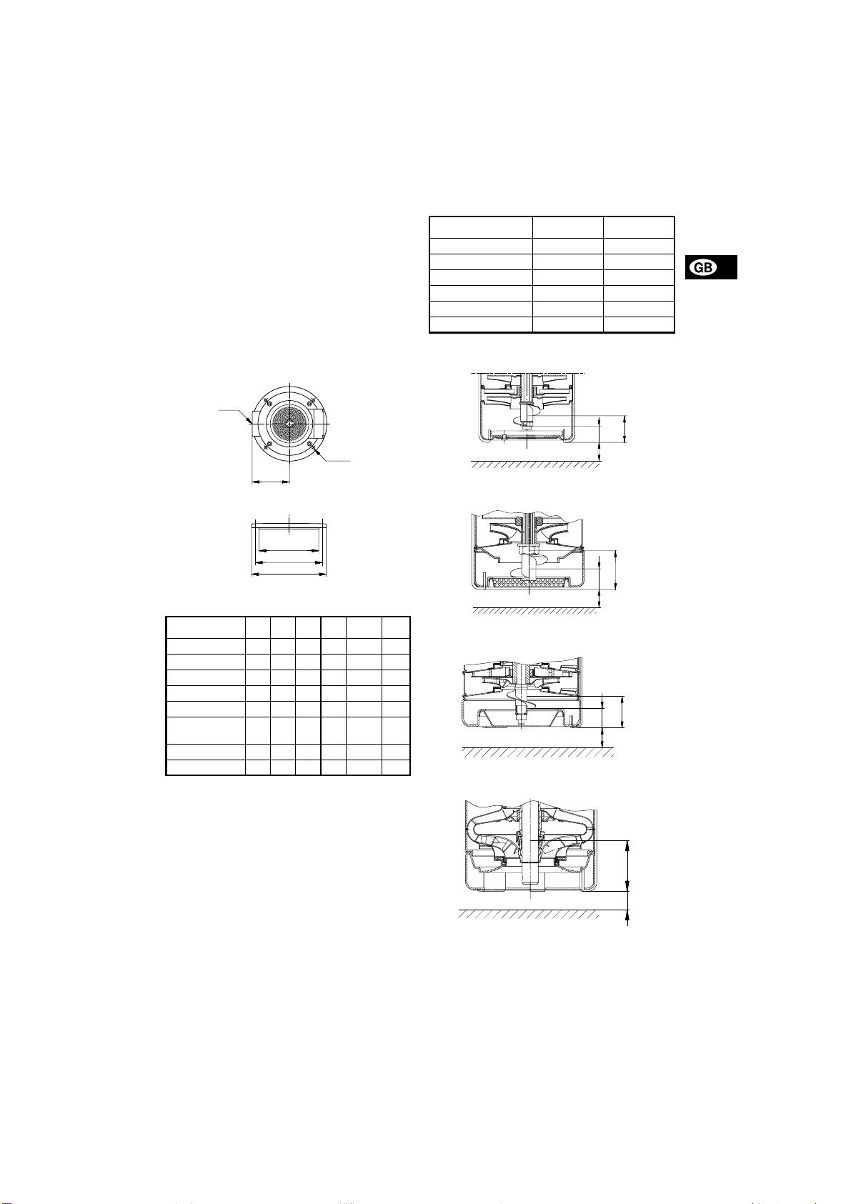
The pump is designed for tank mounting in vertical
position. The pump is positioned in a hole cut into
the cover of the tank (upper side) and is secured to
the tank by four hexagon head screws through the
holes in the mounting flange. It is recommended to fit
a sealing gasket between the pump flange and tank.
If the pump is to be installed horizontally, the drain
hole of the motor stool must be fitted with a plug.
Note: MTR 32, 45 and 64 pumps can only be
mounted in vertical position.
Fig. 1
c
4 x X
L
D1
D2
D3
Pump mounting flange dimensions:
Pump type D1 D2 D3 L C X
CRK 2 and 4 140 160 180 100 Rp 1¼ ø7.5
CRK 8 and 16 200 225 250 125 Rp 2 ø9
CHK 2 and 4 140 160 180 121 Rp ¾ ø7
SPK 1, 2 and 4 100 115 130 64 Rp ¾ ø7.5
SPK 8 140 160 180 100 Rp 1¼ ø7.5
MTH 8, 12 and
16
MTR 32 190 220 250 150 DN 65 ø12
MTR 45 and 64 240 265 290 165 DN 80 ø12
180 210 200 100 Rp 1¼ ø9
4.2 Suction conditions
The bottom of the pump strainer must be at least
25 mm above the bottom of the tank.
The pumps are designed to provide full performance
down to a level of A mm above the bottom of the
strainer.
At a liquid level between A and B mm above the bottom of the strainer, the built-in priming screw will protect the pump against dry running.
Note: MTR 32, 45 and 64 pumps have no priming
screw.
Pump type A [mm] B [mm]
CRK 2 and 4 41 28
CRK 8 and 16 50 25
CHK 2 and 4 37 22
SPK 1, 2, 4 and 8 40 25
MTH 8, 12 and 16 40 25
MTR 32, 45 and 64 70 –
Fig. 2
CRK 2, 4, CHK 2, 4, SPK 1, 2, 4 and 8
B
25 mm
Fig. 3
CRK 8 and 16
TM00 4375 5298
25 mm
Fig. 4
MTH 8, 12 and 16
25 mm
Fig. 5
MTR 32, 45 and 64
25 mm
A
TM00 4841 3897TM00 4842 3897TM01 4326 5298TM01 4335 5298
A
B
A
B
A
5
Page 24
5. Electrical connection
The electrical connection should be carried out in accordance with local regulations.
Never make any connections in the pump
terminal box unless the electricity supply
has been switched off.
If the pump is not connected to an electric
installation, it must be connected to an external mains switch.
The operating voltage and frequency are marked on
the pump nameplate. Please make sure that the motor is suitable for the electricity supply on which it will
be used.
Single-phase GRUNDFOS motors incorporate a
thermal overload switch and require no additional
motor protection.
Three-phase motors must be connected to a motor
starter.
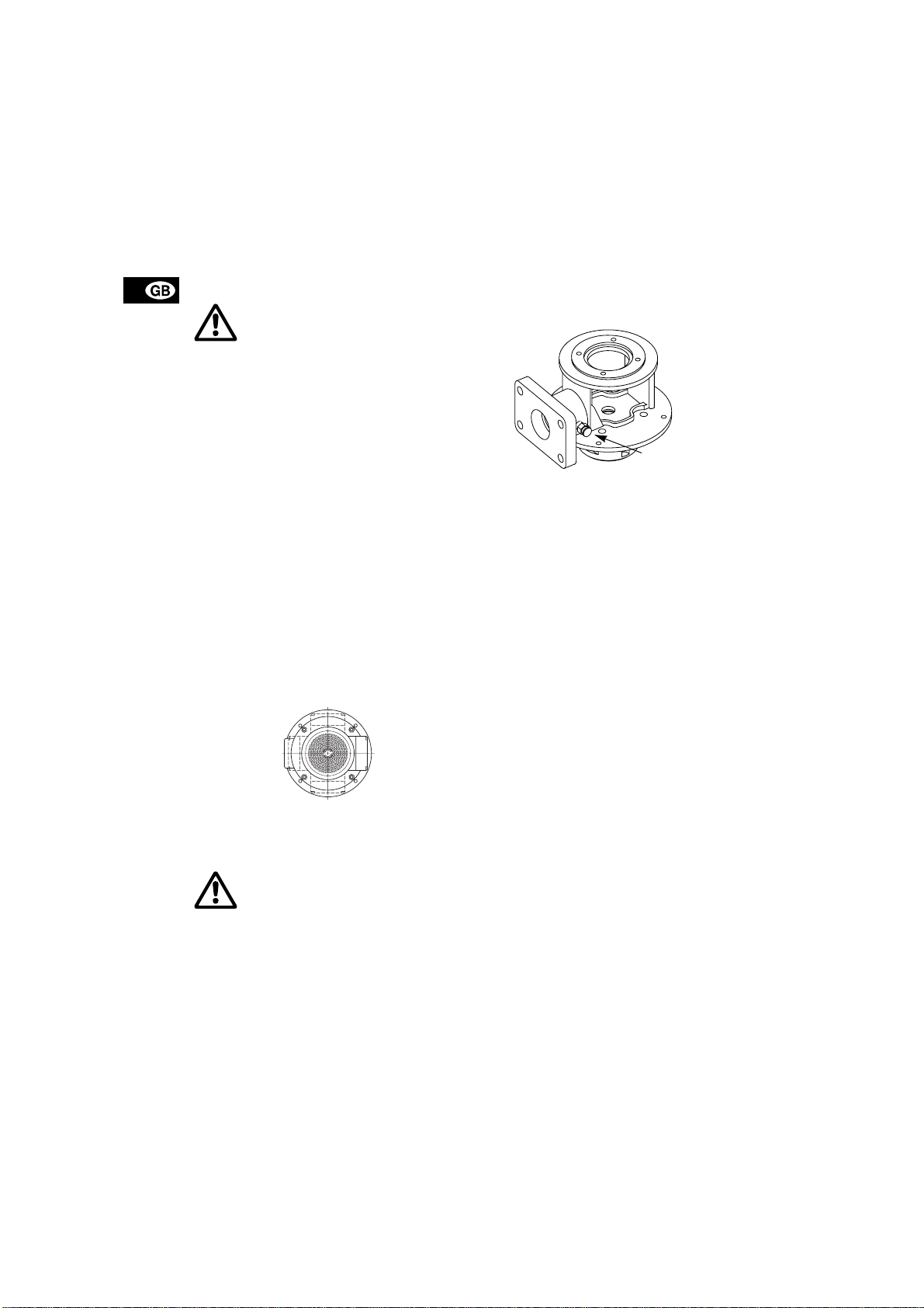
The terminal box can be turned to four positions, in
90° steps. See fig. 6.
Proceed as follows:
1. Remove the coupling guards (CRK, SPK and
MTR). Do not remove the coupling.
2. Remove the four bolts securing the motor to the
motor stool.
3. Turn the motor to the required position.
4. Replace and tighten the four bolts.
5. Replace the coupling guards.
The electric motor should be connected to the supply
as shown in the diagram inside the terminal box
cover.
Fig. 6
270˚
0˚
90˚
180˚
6. Start-up
Pay attention to the direction of the vent
hole and take care to ensure that the escaping water does not cause injury to persons or damage to the motor or other
components.
Before starting the pump, make sure:
• that all pipe connections are tight.
• that the pump body is partly filled with liquid
(partly submerged).
• that the strainer is not blocked by impurities.
Start the pump as follows:
1. Close the isolating valve on the discharge side of
the pump.
2. If the pump is fitted with a vent valve, this valve
must be opened, see fig. 7.
Fig. 7
Vent valve
Vent valve
3. See the correct direction of rotation of the pump
on the motor fan cover. When seen from the top,
the pump should rotate counter-clockwise.
4. Start the pump and check the direction of rotation.
5. Open the discharge isolating valve a little.
6. If the pump is fitted with a vent valve, this valve
must be closed when a steady stream of liquid
runs out of it.
7. Completely open the discharge isolating valve.
The pump has now been vented and is ready for operation.
6. Operation and maintenance
Note: The pump is not allowed to run against a
closed discharge valve for more than approx. 5 minutes as this will cause an increase in temperature/
formation of steam in the pump which may cause
damage to the pump.
6.1 Lubrication and maintenance
Pumps installed in accordance with these instructions require very little maintenance.
The mechanical shaft seal is self-adjusting and has
TM00 4257 2294
wear-resistant seal rings which are lubricated and
cooled by the pumped liquid.
The pump bearings are also lubricated by the
pumped liquid. The motor ball bearings are grease
packed and sealed for life. No further lubrication is
necessary.
Pumps from 4 kW and up have angular contact bearings.
6.2 Filters
Chip trays, filters, etc. should be cleaned at regular
intervals to ensure a correct flow of liquid.
TM01 6428 2399
6
Page 25
6.3 Periodic checks
At regular intervals, depending on the conditions and
time of operation, the following checks should be
made:
• Check the quantity of liquid and operating pressure.
• Check that there are no leaks.
• Check that the motor is not overheating.
• Check the tripping of the motor starter.
• Check that all controls are operating satisfactorily.
If the above checks do not reveal any abnormal operating details, no further checks are necessary.
Should any faults be found, check the symptoms
with section 9. Fault finding chart.
7. Service
If a pump has been used for pumping
liquids which are injurious to human health
or poisonous, it will be classified as contaminated.
A contaminated pump must not be sent to GRUNDFOS for service until GRUNDFOS has received all
necessary details about the pumped liquid, etc.
Otherwise GRUNDFOS can refuse to accept the
pump for servicing.
Possible costs of returning the pump are to be paid
by the customer.
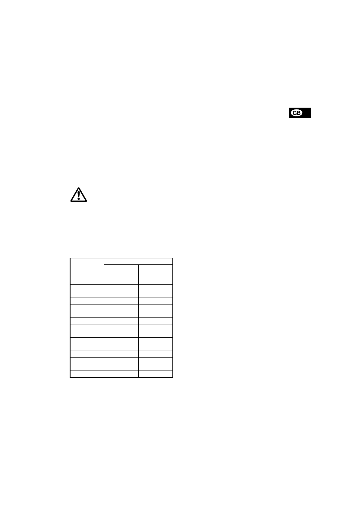
8. Sound pressure level
Motor
[kW]
0.25 <70 <70
0.37 <70 <70
0.55 <70 <70
0.75 <70 <70
1.1 <70 <70
1.5 <70 71
2.2 <70 71
3.0 <70 71
4.0 73 71
5.5 73 78
7.5 73 78
11 80 84
15 72 77
18.5 72 77
22 70 75
30 70 84
LpA [dB(A)]
50 Hz 60 Hz
7
Page 26
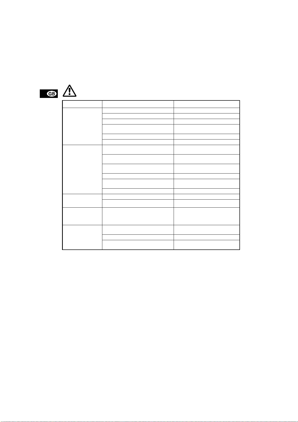
9. Fault finding chart
Before starting work on the pump, make sure that the electricity supply has been switched off and
that it cannot be accidentally switched on.
Fault Cause Remedy
1. Motor does not run
when started.
2. Motor starter overload trips out immediately when supply
is switched on.
3. Motor starter overload trips out occasionally.
4. Motor starter has
not tripped out but
the pump does not
run.
5. Pump runs but
gives no liquid or
pump capacity is
not constant.
a) Supply failure. Connect the electricity supply.
b) Fuses are blown. Replace fuses.
c) Motor starter overload has tripped out. Reactivate the motor protection.
d) Main contacts in motor starter are not
making contact or the coil is faulty.
e) Control circuit is defective. Repair the control circuit.
f) Motor is defective. Replace the motor.
a) One fuse/automatic circuit breaker is
blown.
b) Contacts in motor starter overload are
faulty.
c) Cable connection is loose or faulty. Fasten or replace the cable connec-
d) Motor winding is defective. Replace the motor.
e) Pump mechanically blocked. Remove the mechanical blocking of the
f) Overload setting is too low. Set the motor starter correctly.
a) Overload setting is too low. Set the motor starter correctly.
b) Low voltage at peak times. Check the electricity supply.
a) Chec k 1 a), b), d) and e).
a) Pump strainer partly blocked by impuri-
ties.
b) Liquid level in tank too low. Increase the liquid level.
c) Pump rotates in the wrong direction. Change the direction of rotation of the
Replace contacts or magnetic coil.
Cut in the fuse.
Replace motor starter contacts.
tion.
pump.
Clean the strainer.
motor.
10. Disposal
Disposal of this product must be carried out according to the following guidelines:
1. Use the local public or private waste collection
service.
2. In case such waste collection service does not
exist or cannot handle the materials used in the
product, please deliver the product or any hazardous materials from it to your nearest GRUNDFOS company or service workshop.
8
Subject to alterations.
Page 27

General data
Materials
Pos. Description Materials DIN W.-Nr. AISI/ASTM
Motor stool
Motor stool
2
(no drain hole for
central europe)
7 Coupling guard Stainless steel 1.4301 AISI 304
7a Screw Stainless steel
28 Set screw Stainless steel
76 Nameplate Stainless steel
Extension pipe Stainless steel 1.4301 AISI 304
Intermediate chamber without bearing
Intermediate
3
chamber
Intermediate
3a
chamber
Intermediate
4
chamber
45 Neck ring
45 Neck ring PPS 40% GF
45a Disc for neck ring PTFE
64 Spacing pipe Stainless steel 1.4401 AISI 316
69 Spacing pipe Stainless steel 1.4401 AISI 316
Intermediate chamber with bearing
Intermediate
4a
chamber
Bearing in cham-
4a
ber
45 Neck ring
45a Disc for neck ring PTFE
47a Bearing ring
64a Spacing pipe Stainless steel 1.4401 AISI 316
64b Spacing pipe Stainless steel 1.4401 AISI 316
Bottom intermediate chamber
Intermediate
5a
chamber
45 Neck ring
45 Neck ring PPS 40 % GF
45a Disc for neck ring PTFE
64c Spacing pipe Stainless steel 1.4401 AISI 316
Suction interconnector
Filter:
SPK 1, 2 and 4,
84
ø2 mm holes
SPK 8, ø4 mm
holes
Suction intercon-
121
nector
84b Set screw Stainless steel
Shaft
51 Spline shaft Stainless steel 1.4057 AISI 431
61 Neck ring Stainless steel 1.4301 AISI 304
62 Stop ring Stainless steel 1.4436 AISI 316
64c Neck ring Stainless steel 1.4401 AISI 316
66 Washer Stainless steel 1.4301 AISI 304
67 Lock nut Stainless steel 1.4401 AISI 316
69a Spacing pipe Stainless steel 1.4301 AISI 304
112 Spacing pipe Stainless steel 1.4301 AISI 304
122 Priming screw Stainless steel 1.4401 AISI 316
Cast iron
EN-GJL-200
Stainless steel
(I-version)
Stainless steel 1.4301 AISI 304
Stainless steel 1.4301 AISI 304
Stainless steel 1.4301 AISI 304
Tin/bronze
(only SPK 8)
Stainless steel 1.4301 AISI 304
Ceramic Al
95-100% Hilox
PPS 40% GF
Tin/bronze
(only SPK 8)
Tungsten
carbide
Stainless steel 1.4301 AISI 304
Tin/bronze
(only SPK 8)
Stainless steel 1.4301 AISI 304
Stainless steel 1.4301 AISI 304
0.6020 ASTM 25B
1.4408 AISI 316LN
2.1020.10.
2O3
2.1020.10.
2.1020.10.
SPK, MTH, CRK
Pos. Description Materials DIN W.-Nr. AISI/ASTM
Shaft seal (AUUV)
102 O-ring FKM
103 Neck ring, upper Wolframkarbid
104 Neck ring, lower Wolframkarbid
107 O-ring FKM
108 Spring
111 Disc Stainless steel
Impeller
49 Impeller Stainless steel 1.4301 AISI 304
49d Impeller, lower Stainless steel 1.4301 AISI 304
Strap
26 Strap Stai nles s steel 1.4301 AISI 304
36 Nut Stainless steel
66a Washer Stainless steel
Coupling
8 Coupling
Hexagon socket
9
head screw
10 Shaft pin Stainless steel 1.4301 AISI 304
Stainless steel,
CrNiMo
Cast iron ENGJS-400-15
Sinter metal
Steel
1.4401 AISI 316
0.7040
ASTM
60-40-18
10
Page 28
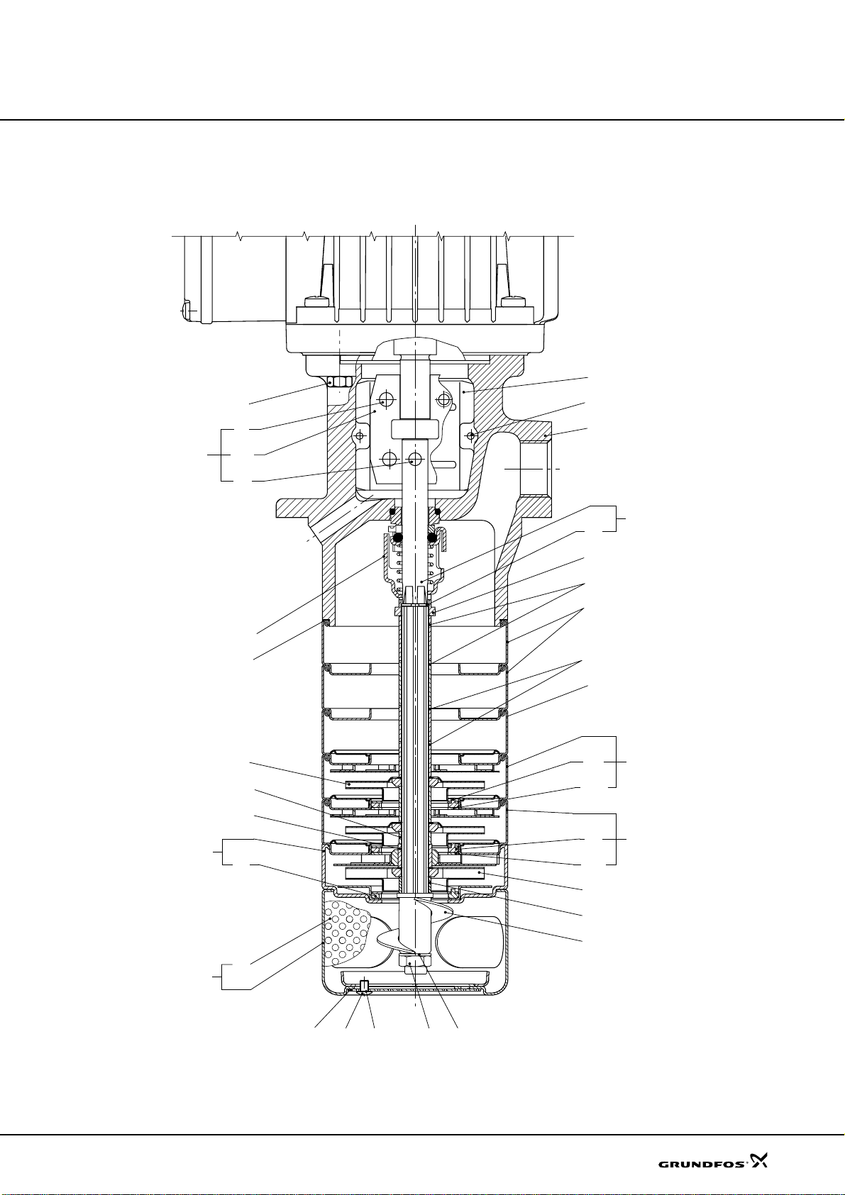
General data
Sectional drawing
SPK, MTH, CRK
7
28
9
8
10a
10
105
37
49
64a
47a
7a
2
51
62
61
69
3a
64
3
445
45a
Fig. 7
5a
121
SPK 1, SPK 2
45
85
84 84b
84c
67 66b
45
45a
49d
64c
122
4a
TM01 9281 1901
11
Page 29
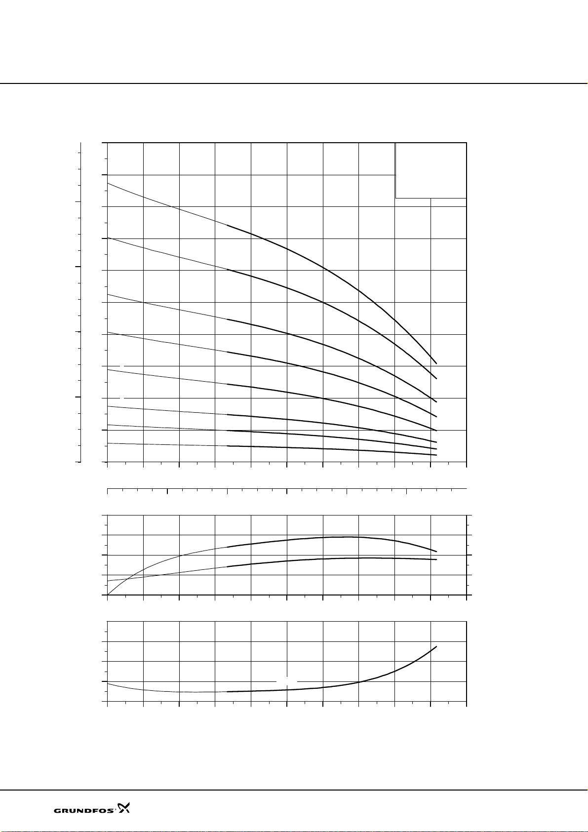
Performance curves
SPK 8
H
p
800
[m]
90
80
70
15
12
[kPa]
SPK 8
50 Hz
SPK 8
50 Hz
ISO 9906 Annex A
600
400
200
60
9
50
7
40
5
30
20
3
2
10
1
0
0
0 20 40 60 80 100 120 140 160
0 2 4 6 8 10
P2
[W]
240
160
80
Q [l/min]
Q [m³/h]
Eta
P2
Eta
[%]
60
40
20
20
0
0 20 40 60 80 100 120 140 160
NPSH
[m]
6
4
2
0
0 20 40 60 80 100 120 140 160
NPSH
0
Q [l/min]
Q [l/min]
TM00 1936 3700
Page 30
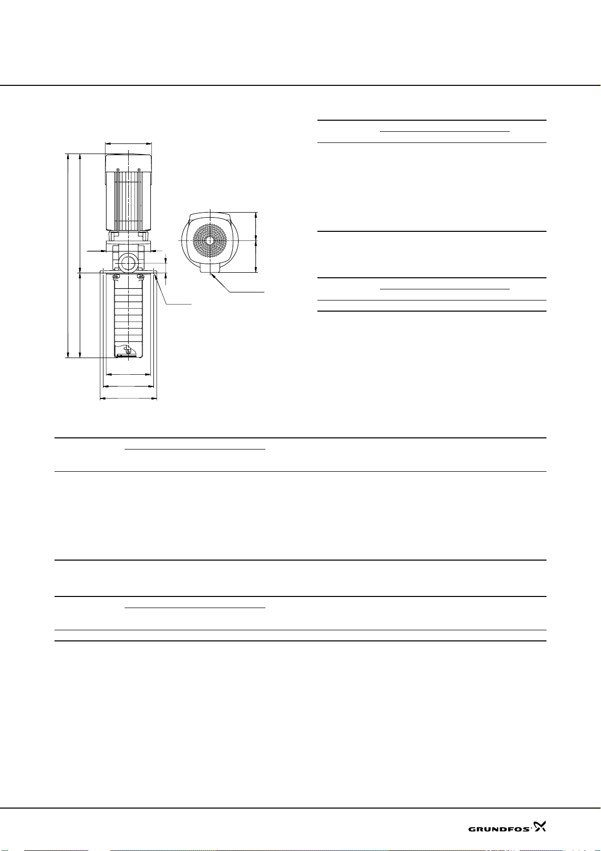
Technical data
Dimensional sketches Dimensions and weights
SPK 8
50 Hz
D1
Pump type
SPK 8-1/1 454 182 273 142 140 109 9.4
SPK 8-2/2 517 224 293 142 140 109 12.6
SPK 8-3/3 559 266 293 142 140 109 13.6
SPK 8-5/5 683 350 333 142 140 109 15.9
SPK 8-7/7 767 434 333 142 140 109 18.3
C
E
D2
A
100
32
Rp 1 1/4
4 x ø7
B
SPK 8-9/9 902 518 384 178 140 110 25.6
SPK 8-12/12 1028 644 384 178 140 110 29.1
SPK 8-15/15 1154 770 384 178 140 110 30.6
The stated weights apply to SPK only. For SPKI, add 1.3 kg.
The electrical data apply to 3 x 220-255/380-440 V, 50 Hz.
SPK with extension pipe
Pump type
SPK 8-15/15 1389 1005 384 178 140 110 33.6
The stated weights apply to SPK only. For SPKI, add 1.3 kg.
Dimensions [mm]
A B C D1 D2 E
Dimensions [mm]
A B C D1 D2 E
Weight
[kg]
Weight
[kg]
ø140
ø160
ø180
TM00 1918 3297
Electrical data 3 x 220-240/380-415 V, 50 Hz
Motor
Pump type
SPK 8-1/1 MG 71A 0.25 1.12/0.65 0.83-0.71 73 5.7-6.2
SPK 8-2/2 MG 71A 0.37 1.66/0.96 0.84-0.76 72 4.8-5.2
SPK 8-3/3 MG 71B 0.55 2.50/1.44 0.84-0.76 72 4.8-5.2
SPK 8-5/5 MG 80A 0.75 3.20/1.86 0.86-0.78 74 5.0-5.5
SPK 8-7/7 MG 80B 1.10 4.60/2.65 0.87-0.79 76 5.2-5.7
SPK 8-9/9 MG 90SA 1.50 5.90/3.40 0.85-0.79 82 6.3-6.9
SPK 8-12/12 MG 90LA 2.20 8.25/4.75 0.87-0.82 84 7.0-7.6
SPK 8-15/15 MG 90LA 2.20 8.25/4.75 0.87-0.82 84 7.0-7.6
The electrical data apply to 3 x 220-255/380-440 V, 50 Hz.
Typ e
P
[kW]
2
Full load current
I
[A]
1/1
Power factor
Cos M
1/1
Motor efficiency
K [%]
I
start
------------ -
I
11e
SPK with extension pipe
Motor
Pump type
SPK 8-15/15 MG 90LA 2.20 8.25/4.75 0.87-0.82 84 7.0-7.6
Typ e
P
[kW]
2
Full load current
[A]
I
1/1
Power factor
Cos M
1/1
Motor efficiency
K [%]
I
start
------------ -
I
11e
21
Page 31
0
1
2
3
4
5 6
7
8
9
Polo-Filtertechnik-Bremen GmbH
In den Ellern 6
28832 Achim
Tel.: 0421/238020
E-Mail: [email protected]
Kunde :
Anlagenbezeichnung:
Zeichnungsnummer :
Kommission :
Hersteller (Firma) :
Pfad (ohne \EPLAN4\P) :
Projektname :
Fabrikat :
Type :
Installationsort :
Projektverantwortlicher :
Teilebesonderheit :
Bearbeitet am:
09.02.06
Haurenherm
SB-A0.4
B05_3643-E1
Polo-Filter-Bremen
Polo-Filter-Bremen
SB-A0.4
Lucka
von (Krzel):
GRA
Anzahl der Seiten :
13
nderung
Datum Name
Datum
Bearb.
Plot
Form.
LCK
20.10.06
EPLAN 4.10 :14.09.93
SB-A0.4
Urspr.
Ers.f.
Polo-Filter-Bremen
Ers.d.
Deckblatt
B05_3643-E1
SB mit Klemmenkasten
=+POLO
ALLG
Bl.
+Z1/2
1
1
Bl.
Page 32
0
1
2
3
5 6
7 8
9
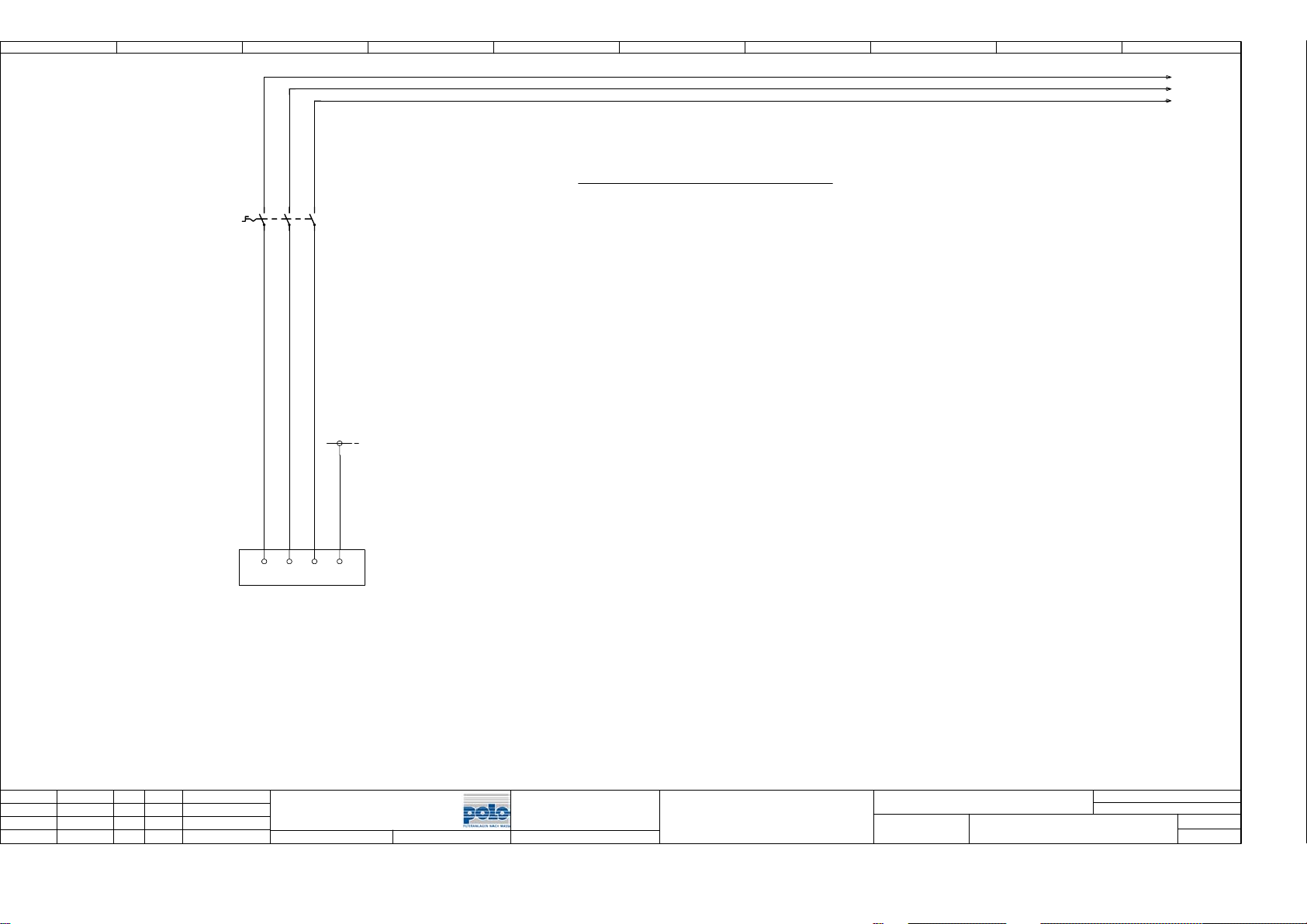
/3.01L1
/3.01L2
/3.01L3
Leistenbezeichnung
-2Q1
4.4
21436
-X1:L1L2 L3PEPE
400V 50Hz
Zuleitung
Vorsicherung
5
4x1,5mmý
10A
=POLO+Z1-X1=Leiste Schaltschrank
=POLO+Z2-X2=Leiste Klemmenkasten Filter
+ALLG/1
nderung
Datum
Name
Datum
Bearb.
Gepr.
Norm
LCK
20.10.06
SB-A0.4
Urspr.
Ers.f.
Polo-Filter-Bremen4 Einspeisung
Ers.d.
B05_3643-E1
SB mit Klemmenkasten
=+POLO
Z1
Bl.
3
2
9
Bl.
Page 33
0
1
2
3
4
5 6
7 8
9
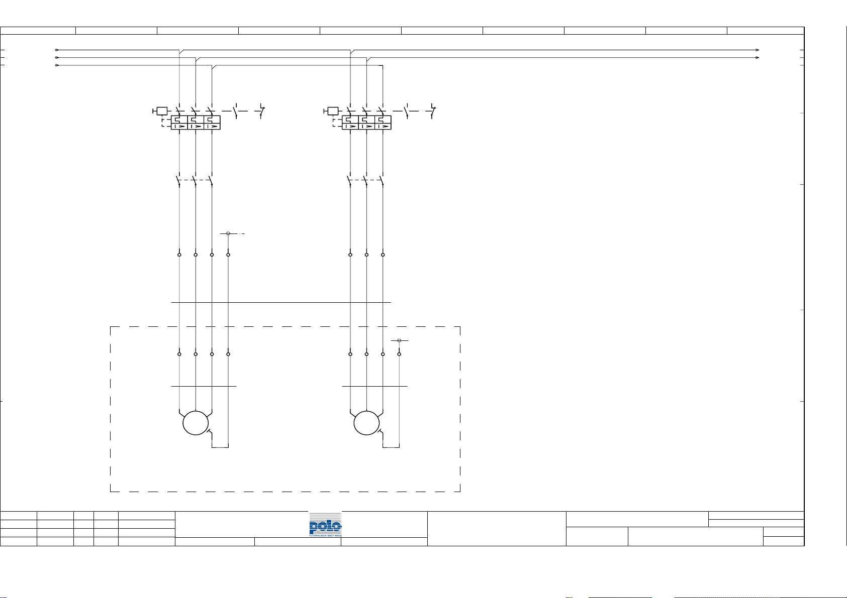
2.9/ 1L1
2.9/ 1L2
2.9/ 1L3
+Z2
Filter
-3Q1
0,28-0,4A
-W1+Z2:
H05VV5-F
7x1,5
-6K1
6.1
-X1 1
-X2 1
12345
3
1
4
2
2
1
2
2
/4.11L1
/4.11L2
-7K1
7.1
12345
3
1
4
2
13
21
14
7.4
22
7.1
6
5
6
13
21
14
7.3
22
6.1
6
-3Q2
1,8-2,5A
5
6
PE
3
4
3
PE
5
6
7
4
5
6
PE
3
4
5
6
7
8
2
nderung
Datum
Name
Datum
Bearb.
Gepr.
Norm
-W3M1:
H05VV5-F
4x1,5
-3M1
0,09 kW
Bandantrieb
LCK
20.10.06
1
2
3
PE
UVW
M
3
~
Ï
Bandantrieb
Polo-Filter-Bremen
Urspr.
Ers.f.
-W3M2:
H05VV5-F
4x1,5
-3M2
0,75 kW
Bandantrieb
1
2
3
PE
UVW
M
3
~
Ï
Betriebspumpe
SB-A0.4
Ers.d.
Antriebe
B05_3643-E1
SB mit Klemmenkasten
=+POLO
Z1
Bl.
4
3
9
Bl.
Page 34
0
1
2
3
4
5 6
7 8
9
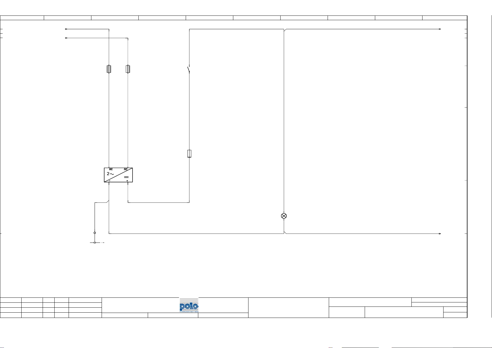
3.9/ 1L1
3.9/ 1L2
-4F1
-4T1
60W
4A
1
-4F2
2
400V
L1
-
24V
4A
1
2
L2
+
-2Q1
2.2
-4F3
2A
/6.0-1L+
13
14
1
2
3
nderung
Datum
Name
Datum
Bearb.
Gepr.
Norm
LCK
20.10.06
-X1 W1
PE
Polo-Filter-Bremen
Urspr.
Ers.f.
SB-A0.4
Ers.d.
X1
-4H1
X2
Steuerung Ein
Steuerspannungsversorgung
B05_3643-E1
SB mit Klemmenkasten
=+POLO
Z1
Bl.
/6.0M-
6
4
9
Bl.
Page 35
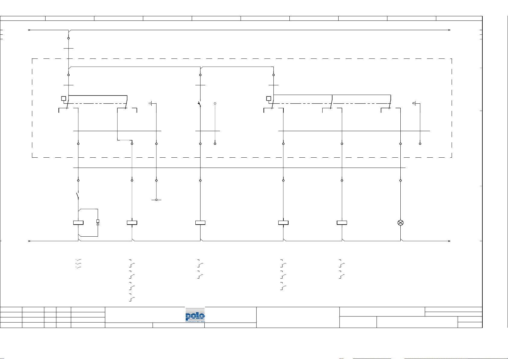
0
1
2
3
4
5 6
7 8
9
4.9/ -1L+
Filter
+Z2
-X1 20
-W2+Z2:
H05VV5-F
12x1,5
-W6S1:
-X2 20
H05VV5-F
4x1,5
-6S1
-W6S1:
H05VV5-F
4x1,5
-W2+Z2:
H05VV5-F
12x1,5
Q
12
-3Q1
1
Schwimmerschalter
1
Filter
11
Niro
21
14 22 PE
2
3
-X2 30
2
-X1 30
13
3.2
14
/7.0-1L+
21
-W6S2:
1
H05VV5-F
PE
24
PE
-6S2
-W6S2:
H05VV5-F
3x1,5
13
PE
14
2
PE
3x1,5
31
3
31
32
PE
32
33
4
33
34
-W6S3:
H05VV5-F
5x1,5
-6S3
-W6S3:
H05VV5-F
5x1,5
22
Schwimmerschalter
11
Q
12 32
Tank
14 24 34 PE
35
5
35
21 31
22
36
6
36
37
7
37
PE
38
PE
4.9/M-
4
nderung
Datum
-6K1
DC24V
Bandantrieb
1 2 3.2
3 4 3.2
5 6 3.2
Datum
Bearb.
GRA
Gepr.
Name
20.10.06
Norm
A1
A2
-6K2
24VDCV
A2
šberlauf
Filter
14
11 8.7
12
24
21 7.1
22
34
31 8.1
32
44
41 8.8
42
Polo-Filter-Bremen
Urspr.
A1
Ers.f.
-6K3
24VDCV
A2
Vlies Ende
14
11 8.2
12
44
41 8.8
42
SB-A0.4
Ers.d.
A1
-6K4
24VDCV
A2
Trockenlaufschutz
14
11 7.1
12
34
31 8.3
32
44
41 8.8
42
Filtersteuerung
A1
-6K5
24VDCV
A2
min. Fllstand
A1
Tank
14
11 8.5
12
44
41 8.8
42
B05_3643-E1
SB mit Klemmenkasten
X1
-6H1
X2
max. Fllstand
Tank
=+POLO
Z1
/7.0M-
Bl.
7
6
9
Bl.
Page 36
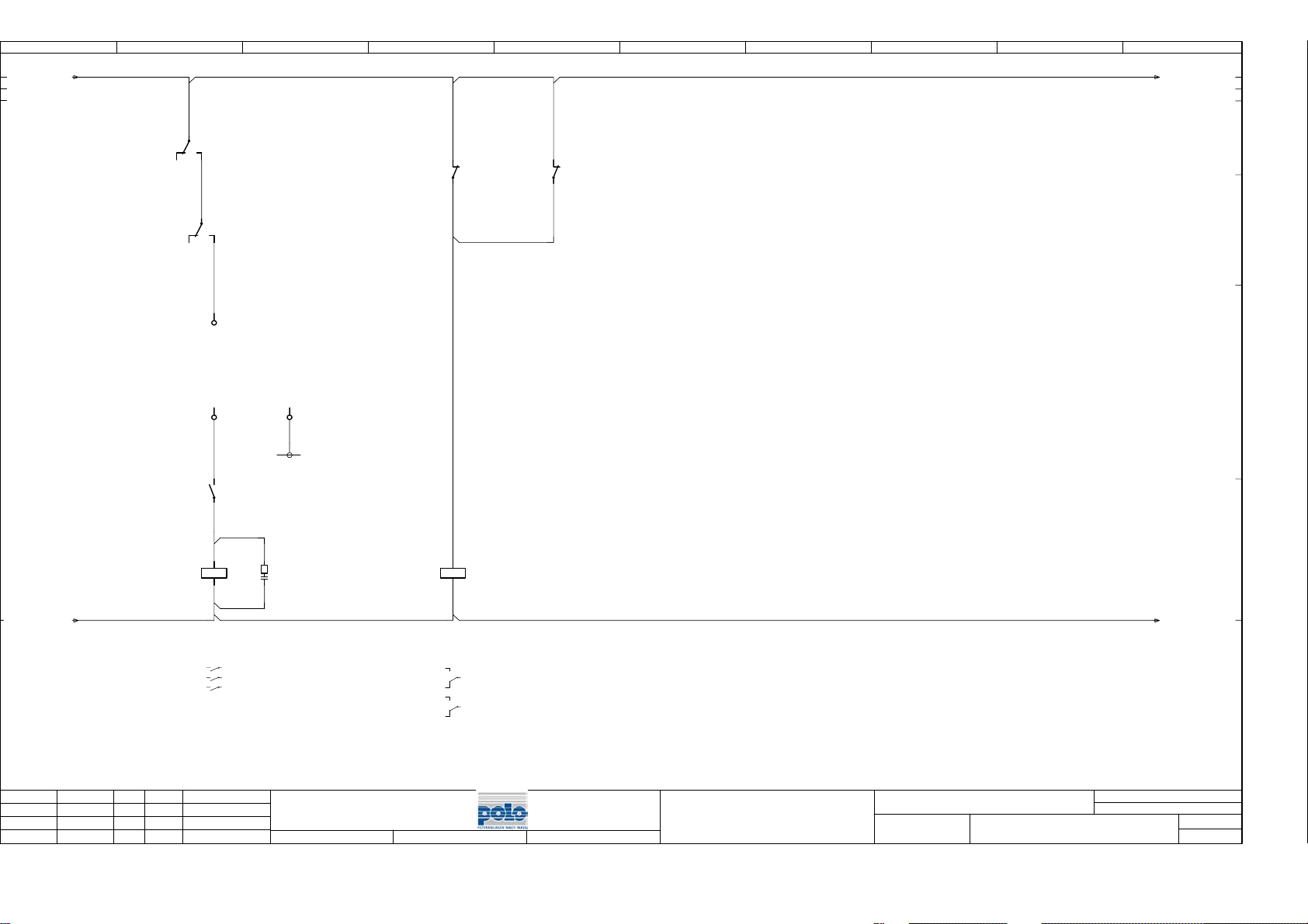
0
1
2
3
4
5 6
7 8
9
6.9/ -1L+
-6K2
6.2
22
-6K4
6.5
-X1 40
externe
Ansteuerung
-X1 41
-3Q2
3.5
21
12
24
11
14
13
14
pE
42
-3Q1
3.3
21
22
-3Q2
3.5
/8.0-1L+
21
22
6.9/M-
6
nderung
Datum
-7K1
DC24V
1 2 3.4
3 4 3.4
5 6 3.4
Betriebspumpe
Datum
Bearb.
GRA
Gepr.
Name
20.10.06
Norm
A1
A2
24VDCV
Motorst”rung
Polo-Filter-Bremen
Urspr.
-7K2
Ers.f.
A1
A2
/8.0M-
14
11 8.6
12
44
41 8.9
42
8
=+POLO
Z1
Bl.
7
9
Bl.
SB-A0.4
Ers.d.
Meldungen
B05_3643-E1
SB mit Klemmenkasten
Page 37
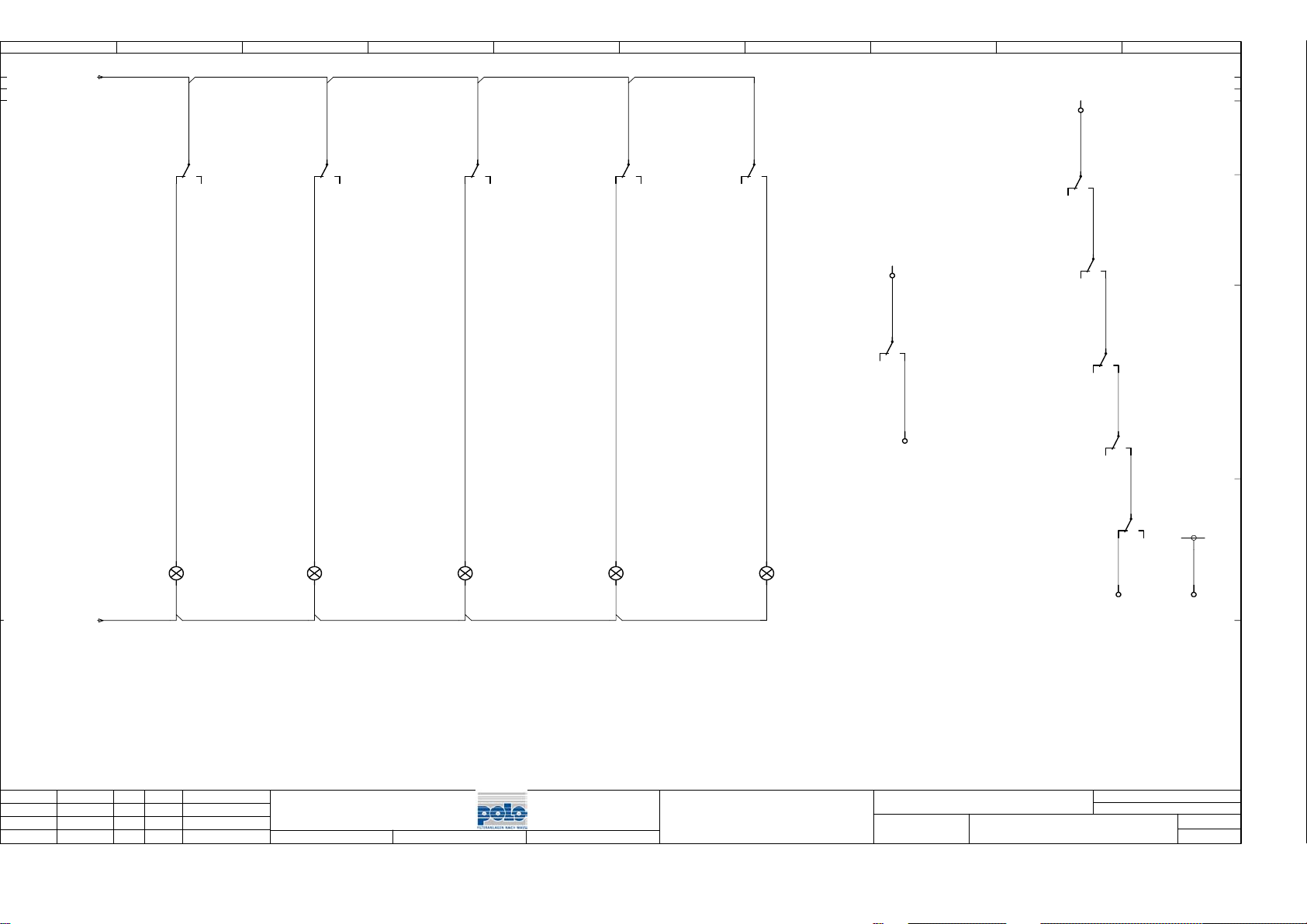
0
7.9/ -1L+
1
2
3
4
5 6
7 8
9
-X1 52
7.9/M-
-6K2
6.2
-8H1
32
X1
X2
31
34
-6K3
6.4
-8H2
12
X1
X2
11
14
-6K4
6.5
-8H3
32
X1
X2
31
34
-6K5
6.7
-8H4
12
X1
X2
11
14
-7K2
7.3
-8H5
12
11
14
X1
X2
-6K2
6.2
-X1 50
11
12
-X1 51
14
-6K2
6.2
-6K3
6.4
-6K4
42
6.5
-6K5
6.7
41
44
41
44
42
41
42
42
-7K2
7.3
-X1 53
44
41
42
44
41
44
PE
54
7
nderung
Datum
šberlauf
Filter
Datum
Bearb.
Gepr.
Name
Norm
GRA
20.10.06
Vlies Ende
Polo-Filter-Bremen
Urspr.
Trockenlaufschutz
Ers.f.
SB-A0.4
Ers.d.
min. Fllstand
Tank
Meldungen
Motorst”rung
šberlauf
Filter
B05_3643-E1
SB mit Klemmenkasten
Filter
st”rungsfrei
=+POLO
Z1
Bl.
9
8
9
Bl.
Page 38
0
1
2
3
5 6
7 8
9
Ziel
Geht
nach...
Funktionstext
Klemmenkasten Filter
Klemmenkasten Filter
externe Ansteuerung
=
Betriebspumpe Ein
šberlauf Filter
=
Filter st”rungsfrei
=
12x1.5mmý=POLO+Z2-W2:H05VV5-F
1
2
3
PE
4
5
6
7
7x1.5mmý=POLO+Z2-W1:H05VV5-F
KabelnameKabeltyp
Ort
Extern
Zielbezeichnung
Betriebsmittelkennzeichnung
1
+Z2-X2
2
+Z2-X2
3
PE
+Z2-X2
+Z2-X2
4
+Z2-X2
5
+Z2-X2
6
+Z2-X2
PE
+Z2-X2
+Z2-X2
+Z2-X2
+Z2-X2
+Z2-X2
+Z2-X2
+Z2-X2
+Z2-X2
Verkabelungsrichtung
Leistenbezeichnung
=POLO+Z1-X1
Leiste Schaltschrank
Anschluá
Klemmen-
nummer
Brcken
Ger„te-
20
30
31
32
33
35
36
37
anschluá
1
1
2
2
3
3
4
4
5
5
6
6
7
7
W1
PE
PE
20
30
31
32
33
35
36
37
40
41
42
50
51
52
53
54
Zielbezeichnung
-6K1
-6K1
-6K1
-7K1
-7K1
-7K1
-4T1
-4H1
-3Q1
-6K2
-PE
-6K3
-6K4
-6K5
-6H1
-6K4
-3Q2
-pE
-6K2
-6K2
-6K2
-7K2
-PE
Intern
Anschluá
X1
13
A1
A1
A1
A1
X1
14
13
11
14
41
42
Start
Kommt
von...
KabelnameKabeltyp
Seite/Pfad
2
4
6
2
4
6
-
/3.2
/3.2
/3.2
/3.2
/3.4
/3.4
/3.4
/4.2
/6.1
/6.1
/6.2
/6.3
/6.4
/6.5
/6.7
/6.8
/7.1
/7.1
/7.2
/8.7
/8.7
/8.8
/8.8
/8.9
8
nderung
Datum
Name
Datum
Bearb.
Gepr.
Norm
09.02.06
GRA
20.10.06
SB-A0.4
Urspr.
Ers.f.
Polo-Filter-Bremen4 Leiste Schaltschrank
Ers.d.
B05_3643-E1
SB mit Klemmenkasten
POLO
=+POLO
Z1
Bl.
+Z2/1
9
9
Bl.
Page 39
0
1
2
3
5 6
7 8
9
Ziel
Geht
nach...
Funktionstext
Bandantrieb
=
=
=
Betriebspumpe
=
=
=
SWS Filter
Vlies Ende
SWS Tank
5x1.5mmý=POLO+Z2-W6S3:H05VV5-F
1
2
3
4
PE
3x1.5mmý=POLO+Z2-W6S2:H05VV5-F
1
2
PE
4x1.5mmý=POLO+Z2-W6S1:H05VV5-F
1
2
3
PE
4x1.5mmý=POLO+Z2-W3M2:H05VV5-F
1
2
3
PE
4x1.5mmý=POLO+Z2-W3M1:H05VV5-F
KabelnameKabeltyp
Ort
Extern
Zielbezeichnung
Betriebsmittelkennzeichnung
1
-3M1
2
-3M1
3
PE
-3M1
-3M1
-3M2
-3M2
-3M2
-3M2
-6S1
-6S2
-6S3
-6S1
-6S1
-6S1
-6S2
-PE
-6S3
-6S3
-6S3
-6S3
Verkabelungsrichtung
Leistenbezeichnung
=POLO+Z2-X2
Leiste Klemmenkasten Filter
Intern
Anschluá
Klemmen-
nummer
Brcken
Ger„te-
11
13
11
14
22
PE
14
14
24
34
PE
anschluá
U
1
V
2
W
3
Ï
4
U
5
V
6
W
7
Ï
8
PE
20
21
22
30
31
32
33
34
35
36
37
38
Zielbezeichnung
+Z1-X1
+Z1-X1
+Z1-X1
+Z1-X1
+Z1-X1
+Z1-X1
+Z1-X1
-PE
+Z1-X1
+Z1-X1
+Z1-X1
+Z1-X1
+Z1-X1
+Z1-X1
+Z1-X1
+Z1-X1
Anschluá
20
30
31
32
33
35
36
37
Start
7x1.5mmý=POLO+Z2-W1:H05VV5-F
12x1.5mmý=POLO+Z2-W2:H05VV5-F
Kommt
von...
KabelnameKabeltyp
Seite/Pfad
1
1
2
2
3
3
PE
4
4
5
5
6
6
7
1
2
3
PE
4
5
6
7
+Z1/3.2
+Z1/3.2
+Z1/3.2
+Z1/3.2
+Z1/3.4
+Z1/3.4
+Z1/3.4
+Z1/3.4
+Z1/6.1
+Z1/6.4
+Z1/6.5
+Z1/6.1
+Z1/6.2
+Z1/6.3
+Z1/6.4
+Z1/6.4
+Z1/6.5
+Z1/6.7
+Z1/6.8
+Z1/6.8
+Z1/9
nderung
Datum
Name
Datum
Bearb.
Gepr.
Norm
09.02.06
GRA
20.10.06
SB-A0.4
Urspr.
Ers.f.
Polo-Filter-Bremen4 Leiste Klemmenkasten Filter
Ers.d.
B05_3643-E1
SB mit Klemmenkasten
POLO
=+POLO
Z2
+STUECK/1
Bl.
1
1
Bl.
Page 40
0
1
2
3
Leistungsberechnung
Benennung Menge Bezeichnung Typen Nummer
=POLO+Z1-2Q1
=POLO+Z1-3Q1
=POLO+Z1-X1
=POLO+Z1-X1
=POLO+Z2-X2
=POLO+Z2-X2
=POLO+Z2-3M1
=POLO+Z1-3Q2
=POLO+Z2-3M2
=POLO+Z1-4F1
=POLO+Z1-4T1
=POLO+Z1-4F2
=POLO+Z1-4F3
=POLO+Z1-4H1
=POLO+Z2-6S1
=POLO+Z1-6K1
=POLO+Z1-6K2
=POLO+Z2-6S2
=POLO+Z1-6K3
=POLO+Z2-6S3
1
Hauptschalter
3LD2103-1TP51
Motorschutzschalter
1
3RV1011-0EA15
Klemme
16
UK5N
Schutzleiterklemme
4
UKSLKG5
Klemme
15
UK5N
Schutzleiterklemme
5
UKSLKG5
Getriebemotor
1
CA 10-G56 M4 0,09KW/0,32A
Motorschutzschalter
1
3RV1011-1CA15
Tauchpumpe
1
SPK8-5/5
Sicherung
1
5SG7 713
Gleichspannungsversorgung
1
GNC 24-2,5
Sicherung
1
5SG7 713
Sicherung
1
5SG7 713
Leuchtmelder
1
3SB32 44-6AA60
Schwimmerschalter
1
SCHWIMMERSCHALTER
Schtz
1
3RT1015-1BB41
Relais
1
553490245090
Grenzschalter
1
GRENZSCHALTER
Relais
1
553490245090
Schwimmerschalter
1
SCHWIMMERSCHALTER
+Z2/1
Datum
09.02.06
Bearb.
nderung
Datum
Name
Gepr.
Norm
Lucka
20.10.06
SB-A0.4
Urspr.
Ers.f.
Ers.d.
Bestellnummer
3LD2103-1TP51
3RV1011-0EA15
UK5N
UKSLKG5
UK5N
UKSLKG5
CA 10-G56 M4 fr SB-Filter
3RV1011-1CA15
SPK8-5/5
5SG7 713
GNC 24-2,5
5SG7 713
5SG7 713
3SB32 44-6AA60
SWS-M01-S04
3RT1015-1BB41
553490245090
3SE2 120-1VW
553490245090
SWS-M05-S04
Polo-Filter-Bremen4 Stckliste
5 6
Hersteller
Lieferant / Ort
Siemens AG
Siemens AG
Phoenix Contact
Phoenix Contact
Phoenix Contact
Phoenix Contact
Flender Getriebebau
Siemens AG
Grundfos
Siemens AG
Block GmbH & Co. K
Siemens AG
Siemens AG
Siemens AG
Polo-Filter-Bremen
Siemens AG
FINDER RELAIS GmbH
Siemens AG
FINDER RELAIS GmbH
Polo-Filter-Bremen
7 8
Artikelnummer
SIE.3LD2103-1TP51
SIE.3RV1011-0EA15
PHOE.UK 5N
PHOE.UKSLKG 5
PHOE.UK 5N
PHOE.UKSLKG 5
FLEN.CA 10-G56 M4
SIE.3RV1011-1CA15
GRUND.SPK8-5/5
SIE.5SG7 713
BLOCK.GNC 24-2,5
SIE.5SG7 713
SIE.5SG7 713
SIE.3SB32 44-6AA60
POLO.SWS-M01-S04
SIE.3RT1015-1BB41
FIN.553490245090
SIE.3SE2 120-1VW
FIN.553490245090
POLO.SWS-M05-S04
B05_3643-E1
SB mit Klemmenkasten
9
STUECK POLO 05.02 LCK
=+POLO
STUECK
Bl.
Pos.
1
2
3
4
5
6
7
8
9
10
11
12
13
14
15
16
17
18
19
20
2
1
2
Bl.
Page 41
0
1
2
3
Leistungsberechnung
Benennung Menge Bezeichnung Typen Nummer
=POLO+Z1-6K4
=POLO+Z1-6K5
=POLO+Z1-6H1
=POLO+Z1-7K1
=POLO+Z1-7K2
=POLO+Z1-8H1
=POLO+Z1-8H2
=POLO+Z1-8H3
=POLO+Z1-8H4
=POLO+Z1-8H5
1
1
1
1
1
1
1
1
1
1
Relais
553490245090
Relais
553490245090
Leuchtmelder
3SB32 44-6AA60
Schtz
3RT1015-1BB41
Relais
553490245090
Leuchtmelder
3SB32 44-6AA20
Leuchtmelder
3SB32 44-6AA20
Leuchtmelder
3SB32 44-6AA20
Leuchtmelder
3SB32 44-6AA20
Leuchtmelder
3SB32 44-6AA20
Bestellnummer
553490245090
553490245090
3SB32 44-6AA60
3RT1015-1BB41
553490245090
3SB32 44-6AA20
3SB32 44-6AA20
3SB32 44-6AA20
3SB32 44-6AA20
3SB32 44-6AA20
5 6
Hersteller
Lieferant / Ort
FINDER RELAIS GmbH
FINDER RELAIS GmbH
Siemens AG
Siemens AG
FINDER RELAIS GmbH
Siemens AG
Siemens AG
Siemens AG
Siemens AG
Siemens AG
7 8
Artikelnummer
FIN.553490245090
FIN.553490245090
SIE.3SB32 44-6AA60
SIE.3RT1015-1BB41
FIN.553490245090
SIE.3SB32 44-6AA20
SIE.3SB32 44-6AA20
SIE.3SB32 44-6AA20
SIE.3SB32 44-6AA20
SIE.3SB32 44-6AA20
9
STUECK POLO 05.02 LCK
Pos.
21
22
23
24
25
26
27
28
29
30
1
nderung
Datum
Name
Datum
Bearb.
Gepr.
Norm
09.02.06
Lucka
20.10.06
SB-A0.4
Urspr.
Ers.f.
Polo-Filter-Bremen4 Stckliste
Ers.d.
B05_3643-E1
SB mit Klemmenkasten
=+POLO
STUECK
+AUFBAUPL/1
Bl.
2
2
Bl.
Page 42
0
1
2
3
5 6
7 8
9
X2
+STUECK/2
nderung
Datum
Name
Datum
Bearb.
Gepr.
Norm
GRA
20.10.06
Leitungskanal
Leitungskanal
Rittal EB 1554.500
200x300x120mm
IP54, RAL 7035
Bolzen (Erdungsbolzen)
Polo-Filter-Bremen4 Klemmenkasten Filter
SB-A0.4
Urspr.
Ers.f.
Ers.d.
1xM25, 6xM20
B05_3643-E1
SB mit Klemmenkasten
=+POLO
AUFBAUPL
Bl.
2
1
2
Bl.
Page 43
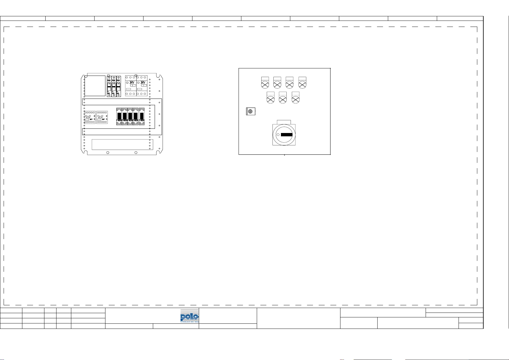
0
1
2
3
5 6
8H3
8H4
6H1
8H1
8H2
4H1
8H5
7 8
9
Leitungskanal
Leitungskanal
X1
1xM25, 5xM20
1
nderung
Datum
Name
Datum
Bearb.
Gepr.
Norm
Rittal AE 1380.500
380x380x210mm
IP54, RAL 7035
GRA
20.10.06
SB-A0.4
Urspr.
Ers.f.
Polo-Filter-Bremen4 Schaltkasten
Ers.d.
B05_3643-E1
SB mit Klemmenkasten
=+POLO
AUFBAUPL
Bl.
2
2
Bl.
 Loading...