

Page 1
Isolation
Pads
Mounting
Brackets
and Screws
Wood Joist
Wood Joist
To p View
of CSW100
Subwoofer
in floor
THIS DOCUMENT APPLIES TO CSW100, CSW155, CSW200, AND SWA500 PRODUCTS
Cutsheet for CSW100/155/200 Custom Install
Subwoofers and SWA500 Amplifier
CSW100
Custom Install Subwoofer
The CSW100 subwoofer is a bandpass design with slot-load venting and has a 10 inch long-throw driver. The
CSW100 fits standard joist spacing and is designed specifically for floor and ceiling installation, or custom enclosures that are at least nine inches (9”) deep. All sound comes from an opening approximately 13 inches long by 3
inches wide. There is an access panel on the back of the subwoofer should the driver have to be removed for service.
Hardware (included)
• 1 Subwoofer
• 4 Mounting Brackets
• 16 - 3/4" Particle Board Panhead Screws
• 16 Washers
• 3 Isolation Pads
• 1 Registration Card
• 1 Owner’s Manual (also available online)
• Plastic molded grille
• 6 Rubber Buttons (to cover grille screw holes)
Protective Cover
A 1/2" thick protective cover of MDF covers the
CSW100 grille opening. This protective cover
(3 - 1/4" x 13") is also the template you will use to
cut the grille opening. Affixed to the MDF cover
is the following label:
All the bass
comes out
of here!
If you choose to use another grille, use one
that doesn’t resonate and caulk it.
.PolkAudio.com
www
Available Finishes: Black
/ 800.377.7655 (USA & Canada) / 410.358.3600 (W
orldwide)
1
Page 2
Dimensions
Installed Weight: 33 lbs.
13"
(33.0 cm)
26 1/4"
(66.7 cm)
26 1/4"
(66.7 cm)
9"
(22.9 cm)
Cutout for grill opening - 3 1/4"
2 Polk Audio Custom Install Pr
Access panel
2"
(5.08 cm)
13"
(33.02 cm)
5/8"
(1.6 cm)
oduct: CSW100
Page 3

Specifications
CSW100 shown with Polk Audio 2" x 12" grille.
PERFORMANCE
DRIVER COMPLEMENT SINGLE LONG-THROW KLIPPEL-ANALYZED 10-INCH DRIVER
POWER HANDLING (WATTS) 250 CONTINUOUS
OVERALL FREQUENCY RESPONSE 27HZ-140HZ
LOWER -3DB LIMIT 33HZ
UPPER -3DB LIMIT
NOMINAL IMPEDANCE
120HZ
8 OHMS
CONNECTIONS
SPEAKER WIRE
MAXIMUM WIRE SIZE ACCOMMODATED 12 AWG
MINIMUM RECOMMENDED 18 AWG
INPUT CONNECTORS HEAVY-DUTY SPRING LOADED
PUSH TERMINALS
Recommended Configuration
Use dedicated SWA500 amplifier to achieve optimal performance as recommended by Polk Audio (see note on SPEX Cards under SWA500).
Factory Support
For product support, contact our service department at 1-800-377-7655 9am to 6pm EST, Monday-Friday,
or contact customer ser
vice at polkcs@polkaudio.com
For more information on the CSW100 and specific installation procedures, log onto
http://www.polkaudio.com/downloads/manuals/home/CSW100_200_Manual.pdf
.PolkAudio.com
www
/ 800.377.7655 (USA & Canada) / 410.358.3600 (W
orldwide)
3
Page 4
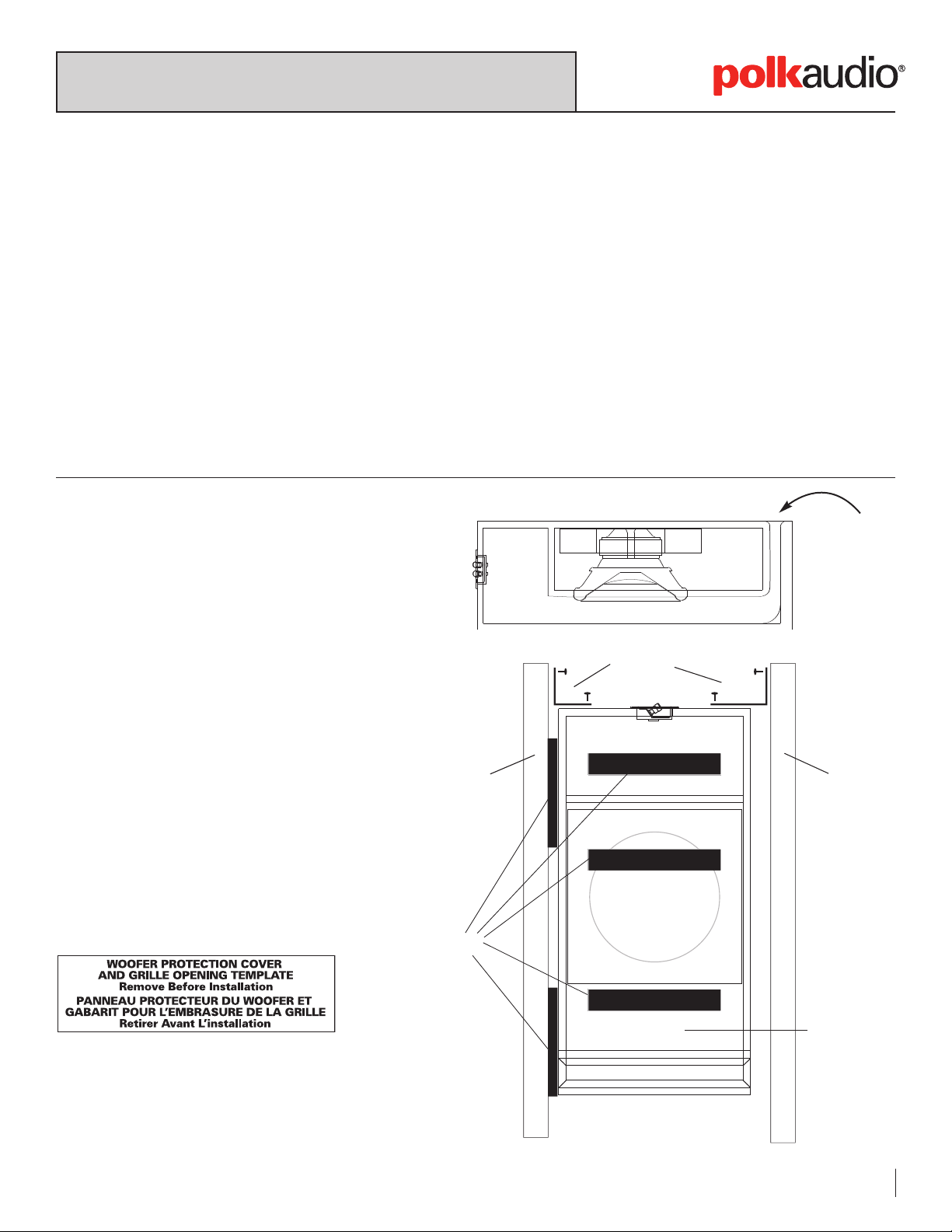
CSW155
Custom Install Subwoofer
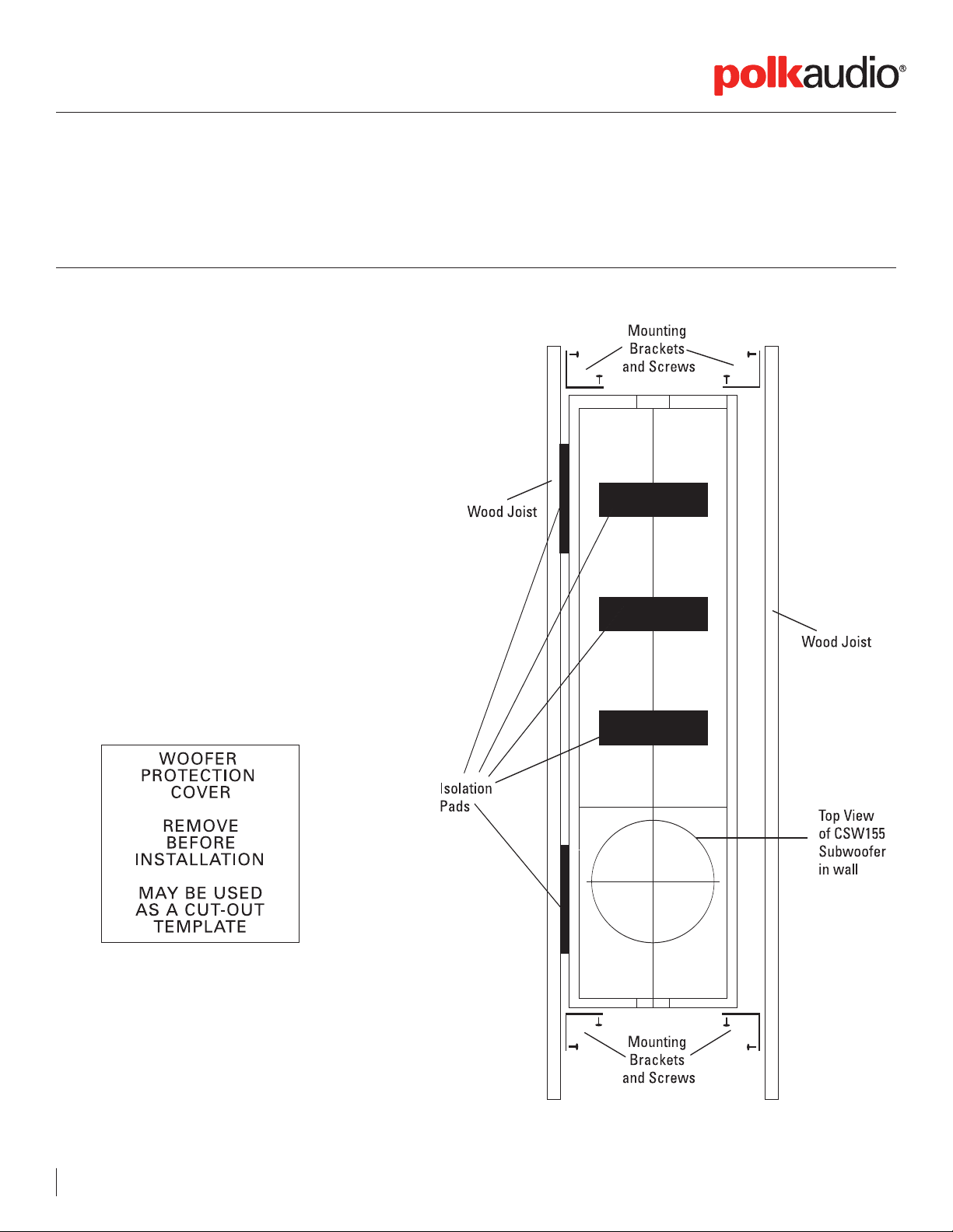
The CSW155 is designed for in-wall placement, either pre-construction or retrofit.
It fits comfortably between 16" OC studs.
Parts included:
1 CSW155 Subwoofer
4 Brackets
16 Screws
16 Washers
11 Isolation Pads (6 installed, 5 included)
1 15 1/2" x 17 1/2" perforated grille with plastic
frame
CSW155 INSTALLATION PROCEDURE
The CSW155 weighs 36 lbs.
Note:
Protective Cover
A 1/2" thick protective cover of MDF covers the
CSW155 grille opening. This protective cover (15
1/2"x17 1/2") is also the template you will use to cut
the grille opening. Affixed to the MDF cover is this
label:
4 Polk Audio Custom Install Pr
oduct: Model Number
Page 5

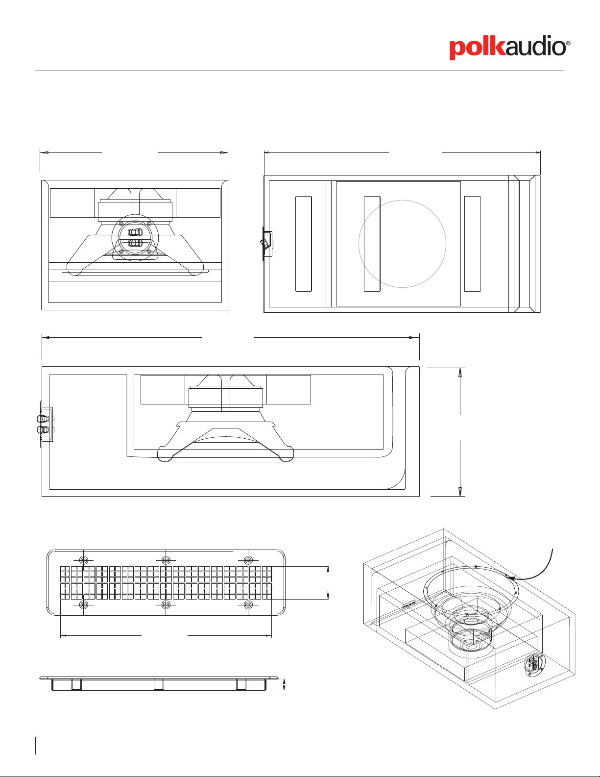
Dimensions
Installed Weight: 48 lbs.
60"
(152.4cm)
14"
(35.56cm)
3 3/8"
(8.6cm)
.PolkAudio.com
www
/ 800.377.7655 (USA & Canada) / 410.358.3600 (W
orldwide)
5
Page 6

Specifications
PERFORMANCE
DRIVER COMPLEMENT SINGLE LONG-THROW KLIPPEL-ANALYZED 10-INCH DRIVER
OVERALL FREQUENCY RESPONSE 30HZ-140HZ
LOWER -3DB LIMIT 36HZ
UPPER -3DB LIMIT 120HZ
NORMAL IMPEDANCE 8 OHMS
CONNECTIONS
SPEAKER WIRE
MAXIMUM WIRE SIZE ACCOMMODATED 12 AWG
MINIMUM RECOMMENDED
INPUT CONNECTORS HEAVY-DUTY SPRING LOADED PUSH
TERMINALS, ONE PAIR PER SIDE
18 AWG
Recommended Configuration
Use dedicated SWA500 amplifier to achieve optimal performance as recommended by Polk Audio (see note on SPEX Cards under SWA500).
Factory Support
For product support, contact our service department at 1-800-377-7655 9am to 6pm EST, Monday-Friday,
or contact Customer Service at polkcs@polkaudio.com
For more information on the CSW155 and specific installation procedures, log onto
http://www.polkaudio.com/downloads/manuals/home/CSW100_155_200_Manual.pdf
6 Polk Audio Custom Install Pr
oduct: Model Number
Page 7

Isolation
Pads
Mounting
Brackets
and Screws
Mounting
Brackets
and Screws
Wood Joist
Wood Joist
To p View
of CSW200
Subwoofer
in floor
CSW200
High Performance Custom Install Subwoofer
The CSW200 is a built-in subwoofer designed specifically for floor and ceiling installation or custom enclosures that
are at least nine inches (9") deep. This subwoofer fits standard joist spacing.
Hardware (included)
• 1 Subwoofer
• 4 Mounting Brackets
• 16 - 3/4" Particle Board Panhead Screws
• 16 Washers
• 3 Isolation Pads
• 1 Registration Card
• 1 Owner’s Manual (also available online)
Grille (not included)
The CSW200 does not include a grille. We recommend
using a 12" x 12" grille, though you may use a variety of
grilles with the CSW200 (10" x 10"or 8" x 14" for example).
To prevent spurious noises, use a grille that doesn’t
resonate and caulk it. To install the CSW200, follow the
procedure that applies to your job.
Protective Cover/Installation
A 1/2" plate of MDF covers the CSW200 woofer to protect
it and the cabinet during shipping and installation. Af
to the MDF cover, you will see the following label:
oduct: CSW200
fixed
.PolkAudio.com
www
vailable Finishes: Black
A
/ 800.377.7655 (USA & Canada) / 410.358.3600 (W
orldwide)
77 Polk Audio Custom Install Pr
Page 8

A
34.
10
866
.1[]
6.50
165.1[]
6.50
165.1[]
Dimensions
Installed Weight: 48 lbs.
13"
(33.0 cm)
34 1/8"
(86.7 cm)
6 1/2"
(16.5 cm)
6 1/2"
(16.5 cm)
34 1/8"
(86.7 cm)
9" (22.9 cm)
8 Polk Audio Custom Install Pr
oduct: Model Number
Page 9

Specifications
CSW200 shown with aftermarket 12" x 12" floor grate.
PERFORMANCE
DRIVER COMPLEMENT SINGLE LONG-THROW KLIPPEL-ANALYZED 10-INCH DRIVER
POWER HANDLING (WATTS) 250 CONTINUOUS
OVERALL FREQUENCY RESPONSE 22HZ-140HZ
LOWER -3DB LIMIT 28HZ
UPPER -3DB LIMIT 120HZ
NORMAL IMPEDANCE 8 OHMS
CONNECTIONS
SPEAKER WIRE
MAXIMUM WIRE SIZE ACCOMMODATED 12 AWG
MINIMUM RECOMMENDED 18 AWG
INPUT CONNECTORS HEAVY-DUTY SPRING LOADED PUSH
IMPORTANT NOTE: The CSW200 is equipped with two sets of binding posts for
installing convenience. Use either set to hook up the subwoofer to the ampli-
. Do not use both sets. Always use one set.
fier
TERMINALS, ONE PAIR PER SIDE
Recommended Configuration
Use dedicated SWA500 amplifier to achieve optimal performance as recommended by Polk Audio (see note on SPEX Cards under SWA500).
Factory Support
For product support, contact our service department at 1-800-377-7655 9am to 6pm EST, Monday-Friday,
or contact Customer Ser
vice at polkcs@polkaudio.com
es, log onto
For more information on the CSW200 and specific installation pr
ocedur
http://www.polkaudio.com/downloads/manuals/home/CSW100_200_Manual.pdf
oduct: CSW200
.PolkAudio.com
www
/ 800.377.7655 (USA & Canada) / 410.358.3600 (W
orldwide)
99 Polk Audio Custom Install Pr
Page 10

SWA500
High Performance Subwoofer Amplifier
Hybrid Class D amplifier, producing 250W Continuous Power into 8 Ohms and 500W Continuous Power into 4 Ohms.
Dimensions
Chassis
3 1/2" H x 17" W x 12 5/8" D (8.89 cm H x 43.18 cm W x 32.07 cm D)
17”
43.18cm
WEIGHT
INSTALLED WEIGHT 9.8 LBS. (4.5 KG.)
SHIPPING WEIGHT 17 LBS. (7.7 KG.)
PERFORMANCE
POWER CONTINUOUS 250W INTO 8 OHMS
500W INTO 4 OHMS
POWER PEAK
BANDWIDTH 15HZ - 250HZ
DISTORTION 0.01%
CROSSOVER FREQ RANGE 40HZ - 120HZ
CROSSOVER SLOPE
POWER REQUIREMENTS 120V 60HZ AC, 6.3 AMPS
AVAILABLE IN 220V? YES
800W
24dB/OCT
3 1/2”
10.16cm
8.89cm
(with
feet)
PROTECTION CIRCUITRY
The SW
t cir
shor
A500 amplifier of
cuit, fuse and over
fers dynamic power contr
-current protection.
ol, thermal protection,
ACCESSORIES
SPEX Cards, which configure EQ, Crossover and Power Control circuitry to
each Polk subwoofer
Rack ears
.
CONNECTIONS
SPEAKER WIRE
MAXIMUM WIRE SIZE ACCOMMODATED 12 AWG
MINIMUM RECOMMENDED 18 AWG
SPEAKER OUT/SPEAKER IN 5-WAY BINDING POSTS
LINE IN/OUTPUTS LFE, LINE IN L/R, LINE OUT L/R
POWER CONNECTIONS 8 FOOT DETACHABLE IEC POWER CORD
4”
10 Polk Audio Custom Install Pr
oduct: Model Number
Page 11

Dimensions (continued)
17”
43.18 cm
Recommended Configuration
SPEX Card: The SPEX Card configures the EQ, Crossover and Power Control
circuitry to match each Polk Subwoofer. The SWA500 Amplifier comes with
SPEX Card(s), one each for the specific Polk In-wall Subwoofer to be installed.
NOTE: One of the SPEX Cards must be installed in the SWA500 Amplifier
for the amplifier to function.
1. Locate the SPEX Card that corresponds to the Polk subwoofer model to
which the SWA500 Amplifier will be connected.
2. Remove the two (2) thumb screws from the rear of the amplifier.
3. Remove the label covering the SPEX Card slot.
4. Connect the ribbon connector coming from the SPEX Card opening to its mating
connector on the SPEX Card.
5. Insert the SPEX Card into the opening and screw the retaining plate onto the back panel.
3 1/2”
8.89 cm
4”
10.16 cm
Factory Support
For product support, contact our service department at 1-800-377-7655 9am to 6pm EST, Monday-Friday,
or contact Customer Service polkcs@polkaudio.com.
For more information on the SWA500 and specific installation procedures, log onto
http://www.polkaudio.com/downloads/manuals/home/SW
oduct: SW
A500
A500_Manual.pdf
.PolkAudio.com
www
/ 800.377.7655 (USA & Canada) / 410.358.3600 (W
orldwide)
1111 Polk Audio Custom Install Pr
 Loading...