

Polhemus PATRIOT User Manual

USER MANUAL
URM03PH170 Rev. B
NOVEMBER 2004

USER MANUAL
{This page intentionally left blank.}

USER MANUAL
Copyright © 2004 by Alken, Inc., dba Polhemus
Colchester, Vermont, U.S.A.
All rights reserved. No part of this publication may be reproduced, stored in a retrieval
system, or transmitted, in any form or by any means, mechanical, photocopying,
recording or otherwise, without the prior written permission of Polhemus. No patent
liability is assumed with respect to the use of the information contained herein. While
every precaution has been taken in the preparation of this manual, Polhemus assumes no
responsibility for errors or omissions. Neither is any liability assumed for damages
resulting from use of the information contained herein.
3SPACE
®
is a registered trademark of Polhemus; PATRIOT™ and LIBERTY™ are
trademarks of Polhemus.
FCC Statement
This equipment has been tested and found to comply with the limits for a Class A digital device,
pursuant to part 15 of the FCC Rules. These limits are designated to provide reasonable
protection against interference when the equipment is operated in a commercial environment.
This equipment generates, uses, and can radiate radio frequency energy and, if not installed and
used in accordance with the instruction manual, may cause interference to radio communications.
Operation of this equipment in a residential area is likely to cause interference in which case the
user will be required to correct the interference at the user’s own expense.
EC – Declaration of Incorporation
This Product Complies with the following European Community Directives:
89/336/EEC as amended by 92/31/EEC
73/23/EEC Low Voltage as amended by 93/68/EEC
The following standards were used to verify compliance with the directives:
EMC: IEC 61326-1:1997+A1:1998 / EN 61326-1:1997+A1:1998
CCISPR 11:1990 / EN 55011:1991-Group 1 Class A
IEC 6100-4-2:1995+A1:1998 / EN 61000-4-2:1995 (ESD 4kV CD, 8kV AD)
IEC 6100-4-3:1995 / EN 61000-4-3:1995 (3V/m 80% AM)
IEC 6100-4-4:1995 / EN 61000-4-4:1995 (0.5kV line-line, 1kV line-earth)
IEC 6100-4-6:1995 / EN 61000-4-6:1995 (3V 80% AM, power line)
Australia/New Zealand: AS/NZS 2064.1
Rev. B i November 2004

USER MANUAL
Safety Notices
i. Warnings
• This instrument contains no user serviceable parts. Do not attempt to service unit.
Return to Polhemus for repair.
• Do not perform any unauthorized modification to the instrument.
• Do not operate the instrument in the presence of flammable gas or fumes. Operation
of any electrical instrument in such an environment constitutes a definite safety
hazard.
• Do not use the instrument in a manner not specified by the manufacturer.
ii. To clean the instrument
If the instrument requires cleaning:
1. Remove power from the instrument.
2. Clean the external surfaces of the instrument with a soft cloth dampened with a
mixture of mild detergent and water.
3. Make sure that the instrument is completely dry before reconnecting it to a power
source.
Rev. B ii November 2004

USER MANUAL
TABLE OF CONTENTS
SAFETY NOTICES.........................................................................................................II
I. WARNINGS........................................................................................................................................ II
II. TO CLEAN THE INSTRUMENT ............................................................................................................. II
TABLE OF FIGURES............................................................................................................................... ....................... v
LIST OF TABLES........................................................................................................................................................... vi
1. GETTING STARTED............................................................................................. 1
1.1 SET UP THE PATRIOT ..................................................................................................................... 1
1.2 INSTALL THE HOST SOFTWARE .........................................................................................................6
1.2.1 USB Driver Installation............................................................................................................6
1.3 USE THE POLHEMUS PIMGR GUI...................................................................................................... 6
1.4 EXPERIMENT WITH PATRIOT DATA ................................................................................................ 9
1.5 TERMS/ACRONYMS......................................................................................................................... 10
2. PATRIOT SYSTEM COMMANDS .................................................................... 18
2.1 OVERVIEW ...................................................................................................................................... 18
2.2 COMMAND SYNTAX........................................................................................................................ 18
2.2.1 Notation .................................................................................................................................. 18
2.2.2 Command Format Notes.........................................................................................................19
Station Wildcard.................................................................................................................................. 19
Default Parameters.............................................................................................................................. 19
2.2.3 Response Format Notes .......................................................................................................... 20
ASCII.................................................................................................................................................. 20
Binary.................................................................................................................................................. 20
Error Responses .................................................................................................................................. 21
2.3 PATRIOT USER COMMAND SET SUMMARY .................................................................................. 22
2.4 PATRIOT ERROR CODE SUMMARY ............................................................................................... 23
2.5 COMMAND REFERENCE................................................................................................................... 24
2.5.1 Configuration Commands....................................................................................................... 24
‘A’ – Alignment Reference Frame.................................................................................................. 25
‘B’ – Boresight ................................................................................................................................ 28
‘F’ – Output Format........................................................................................................................ 30
‘G’ – Source Mounting Frame ........................................................................................................ 32
‘H’ – Hemisphere of Operation....................................................................................................... 34
‘L’ – Stylus Button Function........................................................................................................... 37
‘N’ – Tip Offsets............................................................................................................................. 39
‘O’ – Output Data List.....................................................................................................................41
‘U’ – Set Units ................................................................................................................................ 43
‘X’ – Position Filter Parameters.............................................................................................. ........ 45
‘Y’ – Attitude Filter Parameters...................................................................................................... 48
‘^B’ – Un-Boresight........................................................................................................................ 51
‘^E’ – Set Echo Mode..................................................................................................................... 52
‘^O’ – RS-232 Port Configuration .................................................................................................. 53
‘^R’ – Reset Alignment Frame........................................................................................................ 55
‘^U’ – Active Station State..............................................................................................................56
‘^X’ – Operational Configuration ID.............................................................................................. 59
2.5.2 Operational Commands.......................................................................................................... 61
‘C’ – Continuous Print Output ........................................................................................................ 62
‘P’ – Single Data Record Output..................................................................................................... 63
‘Q’ – Reset Counters....................................................................................................................... 65
‘^K’ – Save Operational Configuration........................................................................................... 66
‘^T’ – Read/Clear BIT Errors.......................................................................................................... 67
‘^V’ – WhoAmI .............................................................................................................................. 69
‘^W’ – Set Default Operational Configuration................................................................................71
‘^Y’ – Initialize System...................................................................................................................72
‘^Z’ – Read Operational Configuration........................................................................................... 73
Rev. B iii November 2004

USER MANUAL
3. COMPONENT DESCRIPTION .......................................................................... 77
3.1 SYSTEM ELECTRONICS UNIT (SEU)................................................................................................ 77
3.1.1 Source Port............................................................................................................................. 77
Source Frequency................................................................................................................................77
3.1.2 Sensor Ports............................................................................................................................ 77
3.1.3 LED Indicator......................................................................................................................... 77
3.1.4 RS-232 I/O.............................................................................................................................. 78
Serial Connector.................................................................................................................................. 78
Hardware Switches.............................................................................................................................. 78
3.2 MAGNETIC SOURCE ........................................................................................................................ 79
3.3 SENSOR(S) ...................................................................................................................................... 80
3.4 STYLUS ........................................................................................................................................... 80
4. SYSTEM OPERATION........................................................................................ 82
4.1 I/O CONSIDERATIONS ..................................................................................................................... 82
4.2 POWERING UP PATRIOT ............................................................................................................... 82
4.3 CONFIGURATION CHANGES............................................................................................................. 82
4.4 OUTPUT UPDATE RATE ................................................................................................................... 82
4.5 OUTPUT CONSIDERATIONS.............................................................................................................. 83
4.6 USEFUL RANGE............................................................................................................................... 83
APPENDIX A. Alignment Reference Frame ............................................................................................................. A-1
APPENDIX B. System Output Data Records ............................................................................................................ B-1
ASCII FORMAT.................................................................................................................................... B-1
BINARY FORMAT............................................................................................................................... B-2
APPENDIX C. Built In Test (BIT) ............................................................................................................................ C-1
INITIALIZATION RESULTS........................................................................................................................ C-1
RUNTIME RESULTS ................................................................................................................................. C-2
APPENDIX D. Limited Warranty and Limitation of Liability................................................................................... D-1
APPENDIX E. Specifications.....................................................................................................................................E-1
APPENDIX F. Customer Service ...............................................................................................................................F-1
Rev. B iv November 2004

USER MANUAL
TABLE OF FIGURES
Figure 1-1 PATRIOT System----------------------------------------------------1
Figure 1-2 Source Connection ---------------------------------------------------2
Figure 1-3 Sensor Connection ---------------------------------------------------2
Figure 1-4 Sensor/Source Test Setup -------------------------------------------3
Figure 1-5 Power Connector -----------------------------------------------------3
Figure 1-6 USB Cable Connection---------------------------------------------- 4
Figure 1-7 RS-232 Cable Connection-------------------------------------------5
Figure 1-8 PiMgr Screen Display -----------------------------------------------7
Figure 1-9 RS-232 Configuration Settings-------------------------------------8
Figure 1-10 PATRIOT Data Record Display----------------------------------8
Figure 1-11 Euler Angles------------------------------------------------------- 15
Figure 3-1 Source Diagram ---------------------------------------------------- 79
Figure 3-2 Sensor---------------------------------------------------------------- 80
Figure 3-3 Stylus ---------------------------------------------------------------- 81
Figure 4-1 Alignment Reference Frame-------------------------------------A-1
Rev. B v November 2004

USER MANUAL
LIST OF TABLES
Table 2-1 ASCII Response Format ---------------------------------------------------------------------20
Table 2-2 Binary Response Format---------------------------------------------------------------------21
Table 2-3 ‘A’ ASCII Response--------------------------------------------------------------------------26
Table 2-4 ‘A’ Binary Response -------------------------------------------------------------------------26
Table 2-5 ‘B’ ASCII Response--------------------------------------------------------------------------29
Table 2-6 ‘B’ Binary Response -------------------------------------------------------------------------29
Table 2-7 ‘F’ ASCII Response--------------------------------------------------------------------------31
Table 2-8 ‘F’ Binary Response--------------------------------------------------------------------------31
Table 2-9 ‘G’ ASCII Response--------------------------------------------------------------------------32
Table 2-10 ‘G’ Binary Response -------------------------------------------------------------------------32
Table 2-11 ‘H’ ASCII Response--------------------------------------------------------------------------35
Table 2-12 ‘H’ Binary Response -------------------------------------------------------------------------35
Table 2-13 ‘L’ ASCII Response--------------------------------------------------------------------------38
Table 2-14 ‘L’ Binary Response--------------------------------------------------------------------------38
Table 2-15 ‘N’ ASCII Response--------------------------------------------------------------------------40
Table 2-16 ‘N’ Binary Response -------------------------------------------------------------------------40
Table 2-17 Output Data Types----------------------------------------------------------------------------41
Table 2-18 ‘O’ ASCII Response--------------------------------------------------------------------------42
Table 2-19 ‘O’ Binary Response -------------------------------------------------------------------------42
Table 2-20 ‘U’ ASCII Response--------------------------------------------------------------------------43
Table 2-21 ‘U’ Binary Response -------------------------------------------------------------------------43
Table 2-22 ‘X’ ASCII Response--------------------------------------------------------------------------46
Table 2-23 ‘X’ Binary Response -------------------------------------------------------------------------47
Table 2-24 ‘Y’ ASCII Response--------------------------------------------------------------------------49
Table 2-25 ‘Y’ Binary Response -------------------------------------------------------------------------50
Table 2-26 ‘^E’ ASCII Response ------------------------------------------------------------------------52
Table 2-27 ‘^E’ Binary Response ------------------------------------------------------------------------52
Table 2-28 ASCII Baud Rate Values --------------------------------------------------------------------53
Table 2-29 ASCII Parity Values--------------------------------------------------------------------------53
Table 2-30 ‘^O’ ASCII Response ------------------------------------------------------------------------54
Table 2-31 ‘^O’ Binary Response ------------------------------------------------------------------------54
Table 2-32 Binary RS-232 Codes ------------------------------------------------------------------------54
Table 2-33 ‘^U[station]’ ASCII Response--------------------------------------------------------------57
Table 2-34 ‘^U0’ ASCII Response-----------------------------------------------------------------------57
Table 2-35 ‘^U’ Binary Response ------------------------------------------------------------------------57
Table 2-36 ‘^X’ ASCII Response ------------------------------------------------------------------------59
Table 2-37 ‘^X’ Binary Response------------------------------------------------------------------------60
Table 2-38 ‘P’ ASCII Response--------------------------------------------------------------------------63
Table 2-39 ‘P’ Binary Response--------------------------------------------------------------------------64
Table 2-40 ‘^T’ ASCII Response ------------------------------------------------------------------------68
Table 2-41 ‘^T’ Binary Response ------------------------------------------------------------------------68
Table 2-42 ‘^V’ ASCII Response ------------------------------------------------------------------------69
Table 2-43 ‘^V’ Binary Response ------------------------------------------------------------------------70
Table 2-44 ‘^V[station] ASCII Response---------------------------------------------------------------70
Table 2-45 ‘^V[station]’ Binary Response--------------------------------------------------------------70
Table 2-46 ‘^Z’ ASCII Response Header---------------------------------------------------------------73
Table 2-47 ‘^Z’ ASCII Response ------------------------------------------------------------------------74
Table 2-48 ‘^Z’ Binary Response ------------------------------------------------------------------------75
Table 3-1 LED conditions -------------------------------------------------------------------------------78
Table 3-2 RS-232 Pin Outs ------------------------------------------------------------------------------78
Table 3-3 Switch Settings--------------------------------------------------------------------------------79
Table 4-1 BIT Results DWORDs---------------------------------------------------------------------C-1
Table 4-2 Source BIT Results ------------------------------------------------------------------------- C-1
Table 4-3 Global Sensor BIT Results ---------------------------------------------------------------- C-2
Table 4-4 Sensor Channel BIT Results --------------------------------------------------------------C-2
Table 4-5 Runtime BIT Error Codes ----------------------------------------------------------------- C-3
Rev. B vi November 2004
USER MANUAL
1. Getting Started
Congratulations on buying the latest, most cost-effective 3D tracking system yet! This
section of the user manual has been provided to help get your project under way as
quickly as possible.
As with any new system, there are two ways to get started with your PATRIOT system:
you could “wing it,” which involves a great deal of assumptions based on previous
experience and/or visual inspection, and hope for the best. Alternatively, you could sit
down and read the whole manual, line-by-line, and then start. What we provide here is a
middle ground to cover the basics to get you going quickly. However, this approach does
not preclude using the manual as a precise guide, reference and final arbiter.
1.1 Set Up the PATRIOT
NOTE: This approach assumes the use of a single sensor, availability of a USB or COM
Port on a computer with either Windows 2000 or Windows XP, and that the Polhemus
PiMgr GUI is installed on the computer. See
instructions.
Install the Host Software on page 6 for
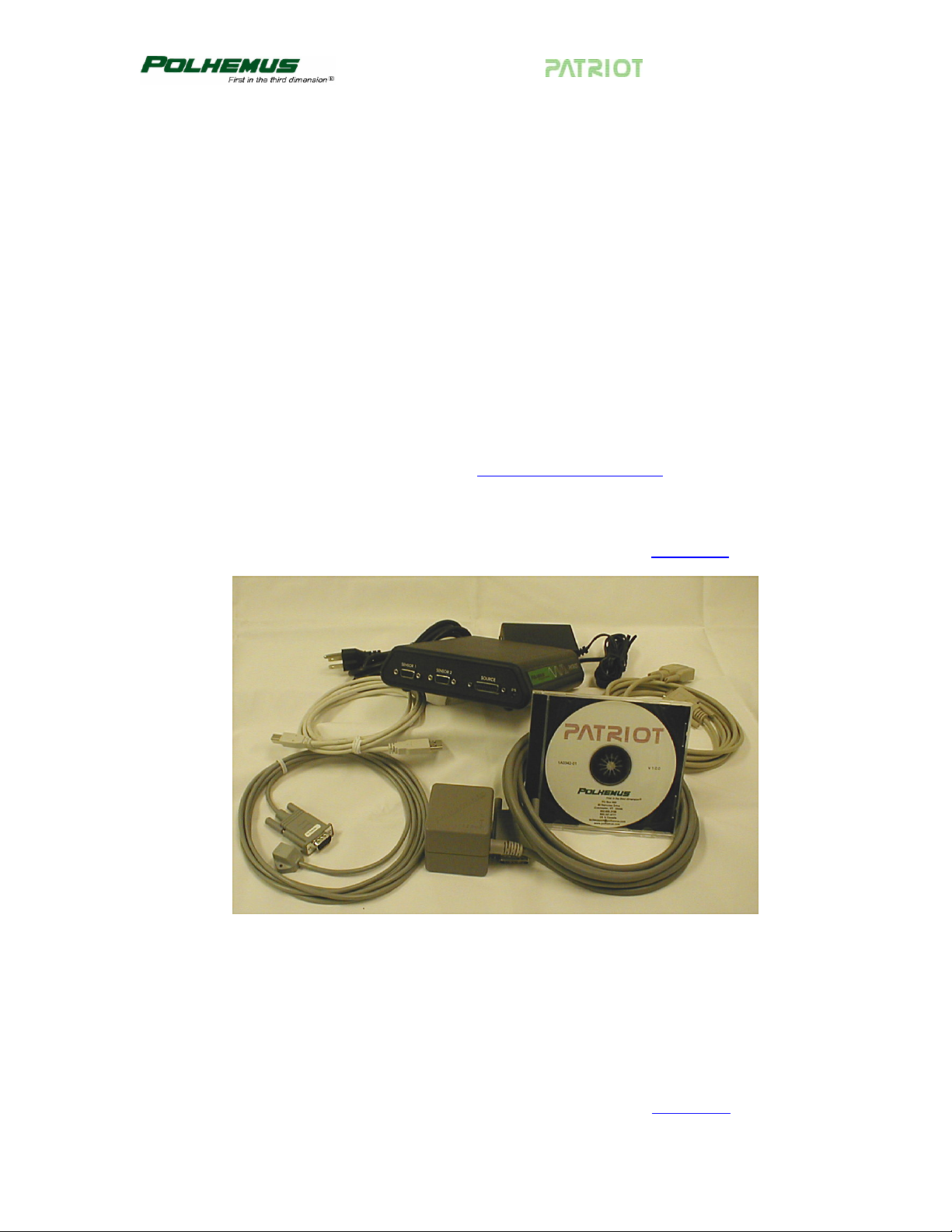
1. Unpack the PATRIOT SEU, source, sensor(s), USB and RS-232 cables,
PATRIOT Host Software CD, power supply and cables. See
Figure 1-1 PATRIOT System
Figure 1-1.
2. Set up the PATRIOT system close to your host computer and away from large
metal objects like file cabinets, metal desks, etc., and away from the floor and
walls.
3. Identify the source (the two-inch gray cube) and insert the source connector into
the source receptacle, being careful to firmly engage it. Using your fingers,
tighten the two retaining screws to secure the connector. See
Rev. B 1 November 2004
Figure 1-2.
USER MANUAL
Figure 1-2 Source Connection
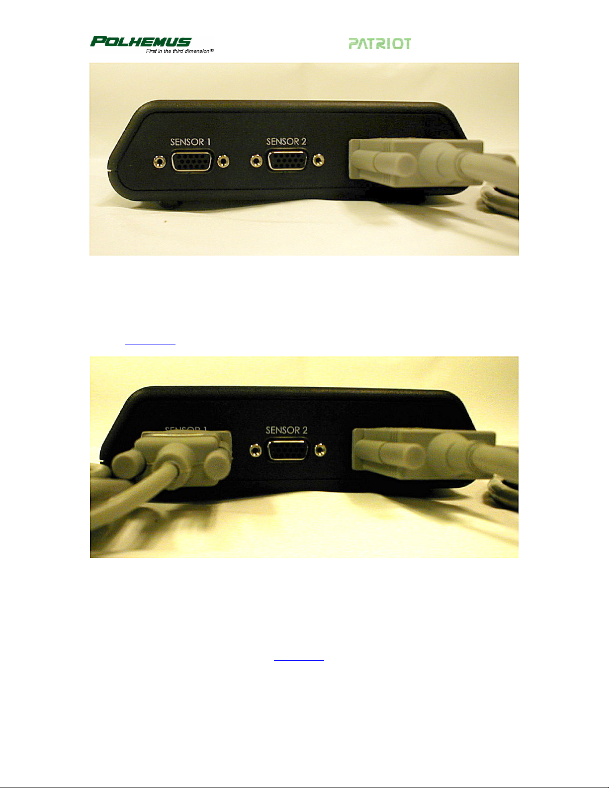
4. For getting started, use only one sensor. Identify the sensor and insert it into either
of the sensor receptacles as shown below. Firmly engage and lock the sensor
connector into place in the same manner as the source connector in step 3. See
Figure 1-3.
Figure 1-3 Sensor Connection
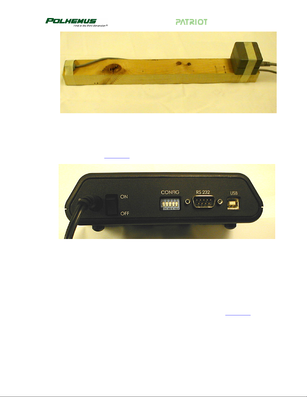
5. For testing purposes, it is convenient to mount both the source and the sensor on a
single block of wood (2x4 or equivalent) about 16 inches apart. Exact placement
of the source and sensor is not important for this test; just make sure the cables of
both devices are not routed tightly together and that they come off opposite
ends of the wooden block. See
Rev. B 2 November 2004
Figure 1-4.
USER MANUAL
Figure 1-4 Sensor/Source Test Setup
6. Ensure the power switch is in the OFF position (logic “0”, DOWN). With the
separate power supply UNPLUGGED from the wall, connect the power input
cable to the PATRIOT. The power supply can now be plugged into a 110/220
VAC outlet. See
Figure 1-5.
Figure 1-5 Power Connector
USB or RS-232 Communication
Only one I/O port (USB or RS-232) can be active at a time.
• For USB, continue with step 7.
• For RS-232, skip to step 11.
For USB Communication:
7. Identify the USB cable and insert it into the receptacle as shown in
Figure 1-6.
Connect the other end of the USB cable to the host computer.
Rev. B 3 November 2004

USER MANUAL
Figure 1-6 USB Cable Connection
8. At this point, you may turn on the PATRIOT system using the power switch
located on the back panel of the SEU. A system status indicator located on the
front panel should flash red for 5 to 10 seconds indicating self-test and set-up.
When these routines are completed, the indicator will reflect system status as
follows:
• Steady green
• Flashing red
System operational – passed startup testing.
Failed self-test and set-up.
9. The host should respond with a “Found New Hardware” message. Follow the
hardware wizard to install the required drivers from the PATRIOT Host Software
CD-ROM. For step-by-step instructions, refer to
USB Driver Installation on page
6.
NOTE: Once the USB cable is connected to PATRIOT, it cannot return to RS-232 mode
without removing the USB connection and restarting (power OFF/ON).
10. You may now use the Polhemus PiMgr GUI to exercise the system. If you have
not yet installed the Host Software, continue to
Install the Host Software on page
6. Otherwise, continue to Use the Polhemus PiMgr GUI on page 6 and
Experiment with PATRIOT Data on page 9.
For RS-232 Communication:
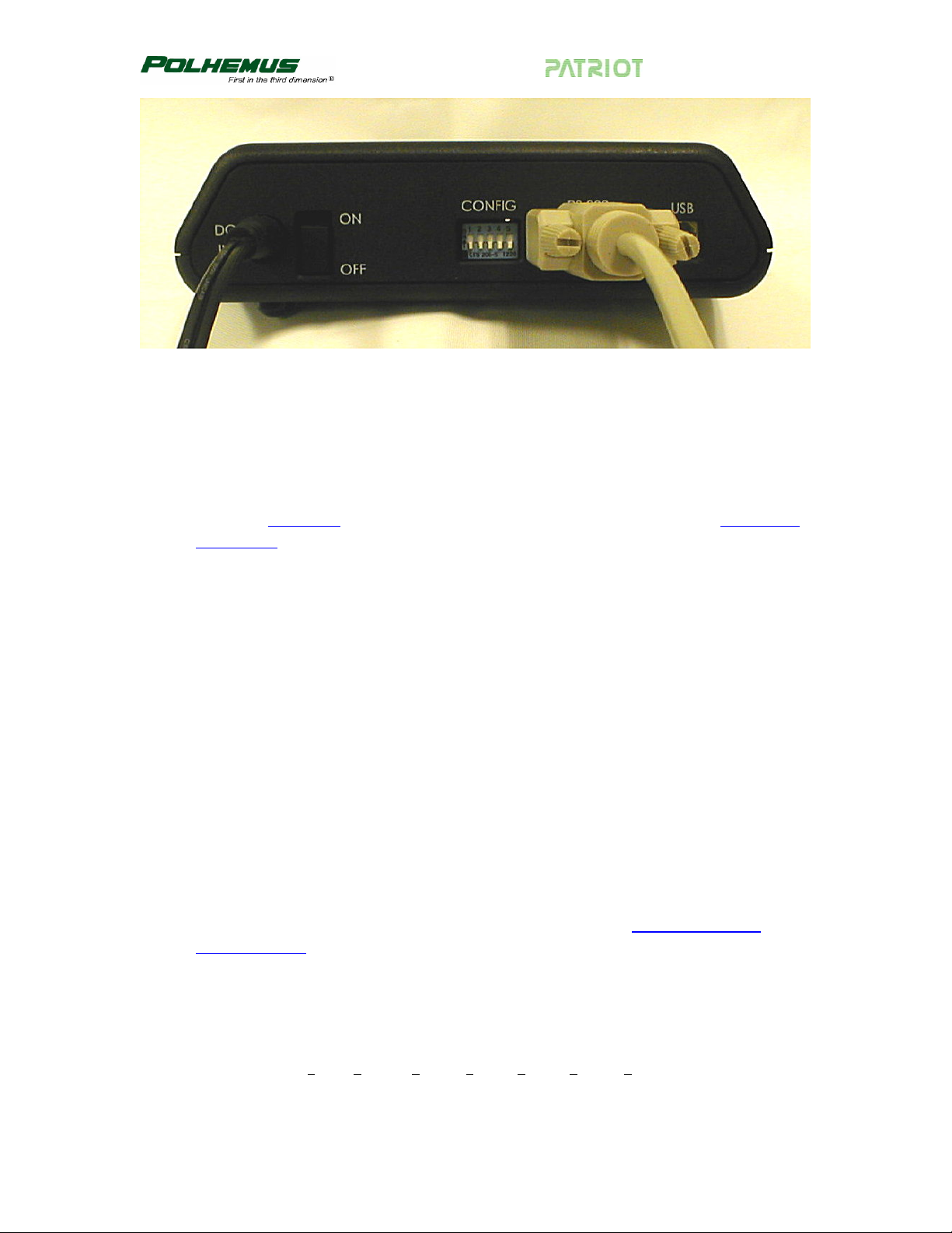
11. Locate the RS-232 cable and insert it into the receptacle as shown in
Figure 1-7.
Most PC hosts have a 9 pin, male “D” type connector for COM1. If you are using
COM1, plug the remaining end of the cable into the COM1 port of the host PC,
engage, and lock as before.
If your host computer has a 25 pin “D” connector for the RS-232 port, you will
need a 9 to 25 pin “D” connector adapter with the proper genders. Note that this
adapter must not compromise the NULL MODEM sense of your cable.
Rev. B 4 November 2004
USER MANUAL
Figure 1-7 RS-232 Cable Connection
12. You may now exercise the system. To use the Polhemus PiMgr GUI, return to
step 10. With the RS-232 connection, you may also use PATRIOT’s ASCII
interface through the Windows HyperTerminal program.
To do this, first set PATRIOT’s “CONFIG” hardware switches to all DOWN as
shown in
on page 78
Figure 1-7. (RS-232 switch settings are described in detail in RS-232 I/O
.)
Next, start the HyperTerminal program and create a serial connection using these
switch settings. The steps are as follows:
• Navigate to HyperTerminal from the Windows Start menu. StartÖAll
ProgramsÖAccessoriesÖCommunicationsÖHyperTerminal.
• In HyperTerminal, enter a session name, choose an icon, and click OK
• In the “Connect using” field, select the desired COM port (COM1) and click OK.
• In the “Bits per second” field, select 115200.
• In the “Data bits” field, select 8 (default).
• In the “Parity” field, select None (default).
• In the “Stop bits” field, select 1 (default).
• In the “Flow control” field, select None and click OK.
13. You should now have a serial connection opened to PATRIOT. Turn PATRIOT
on. In 5 to 10 seconds, you will see “PATRIOT Ready!” in the HyperTerminal
screen.
14. Collect a single data record from PATRIOT by typing the
Record Outpu
t command (see page 63) in the HyperTerminal screen. PATRIOT
‘P’ – Single Data
will respond with a single frame of position and orientation data. The data
displayed in the HyperTerminal screen consists of a station number and six
columns of data as follows (these values represent an arbitrary placement of the
sensor and source.):
1 2 3 4 5 6 7
01 16.082 -0.387 0.713 3.051 1.126 -0.674
Rev. B 5 November 2004

USER MANUAL
15. Continue experimenting with the position and orientation data. See Experiment
with PATRIOT Data
orientation data, carefully go over the above procedure in a systematic fashion,
checking connections and switch settings especially. If you still need assistance,
refer to
Customer Service on page F-1.
on page 9. If the system fails to produce position and
1.2 Install the Host Software
NOTE: PATRIOT Host Software is intended to be installed on a computer running
Windows 2000 or Windows XP only.
• Insert the PATRIOT Host Software CD-ROM into your computer’s CD-ROM drive.
• If the PATRIOT Host Software Installation Panel does not run automatically, then
navigate to the CD-ROM drive using Windows Explorer. Run “Setup.exe”. The Host
Software Installation Panel will appear. Click on “Install Host Software.” The
installation wizard will walk you through the installation.
• For simplicity, it is recommended that you use the default installation settings
suggested by the installation wizard.
• When the installation is complete, if you are planning to use your computer’s USB
port to connect to the PATRIOT System, leave the CD-ROM in the drive. It will be
needed when the initial USB connection is made.
• If you are not planning to use the USB port, you may remove the CD-ROM from the
drive now.
1.2.1 USB Driver Installation
• When PATRIOT is connected via USB to a Windows host for the first time, the host
will display a “Found New Hardware” message. The host will then launch the
“Found New Hardware Wizard” to locate and install the USB drivers for PATRIOT.
• If the CD-ROM is not already in the drive, load it now.
• When the Found New Hardware Wizard displays, select the “Install software
automatically” option and click “Next.”
• The wizard will install the PATRIOT Loader. When it has completed, click “Finish.”
• The same process will be launched again automatically to install the Polhemus
PATRIOT USB Driver. Repeat the same selections and the process will be complete.
1.3 Use the Polhemus PiMgr GUI
If you selected the default settings when you installed the PATRIOT Host Software on
your computer, you will find a shortcut to the PiMgr application on your Windows 2000
or XP desktop. It looks like this:
Rev. B 6 November 2004

USER MANUAL
Otherwise, navigate to the program through the windows Start menu:
StartÖAll ProgramsÖPolhemusÖPiMgr
The initial PiMgr screen will look like this:
Figure 1-8 PiMgr Screen Display
1. With no PATRIOT system connected, notice that the
lower right corner. Once connected, the icon will change to
icon appears in the
.
2. If the PATRIOT system is already powered up and connected to the computer, the
PiMgr will discover the connection immediately upon startup. If not, you will
need to manually create the connection once you have powered up PATRIOT. To
do this, first you must select the type of connection you wish to create.
3. If you want to create a USB connection, skip to step 4. PiMgr defaults to a USB
connection. If you want to create an RS-232 connection, first configure the serial
port settings by opening the Device Configuration dialog. Open this dialog off
the Device menu: DeviceÖDevice Configuration…, and select the Connection
tab. Select the RS-232 Connection Type on the left, and the appropriate RS-232
Properties on the right. Then Click OK.
Rev. B 7 November 2004

USER MANUAL
Figure 1-9 RS-232 Configuration Settings
4. To create a connection, click the Connect button on the PiMgr toolbar:
.
When the connection has been established, the connection icon at the lower right
will change to
.
5. To collect a single frame of motion data from the PATRIOT system, click the
Single button on the toolbar:
6. You can also do this by typing ‘p’ or ‘P’ anywhere on the PiMgr window. This
will cause PiMgr to request a single data frame from the PATRIOT system. The
contents of the frame will be displayed in the text window at the top of the PiMgr
display. The airplane image(s) in the graphics portion of the screen will move to
the retrieved position and orientation:
Figure 1-10 PATRIOT Data Record Display
The text portion of the screen will display the retrieved position and orientation:
Position in inches Euler Orientation in degrees
Station Number X Y Z Azimuth Elevation Roll
1 0.389 34.603 0.000 -1.000 0.000 88.000
Rev. B 8 November 2004

USER MANUAL
1.4 Experiment with PATRIOT Data
1. Take some initial samples of data using the ‘P’ – Single Data Record Output
command (see page 63
relative to the source (
change regardless of the number of data samples you take.
2. Remove the sensor, move it approximately six inches toward the source, secure it
in place, and take another single data frame. The value of the X position data will
decrease by approximately six inches. The Y and Z values will remain roughly the
same as the original data. If you left the attitude of the sensor approximately the
same as it was when you started, then the attitude data also will be approximately
the same.
3. Again, remove the sensor and without moving its position, try twisting it in
azimuth (in the same plane as the wood support) approximately 45 degrees and
lock it down with tape. Now collect another data frame. The first four columns
will be approximately as they were in step 1, but the Azimuth data in column 5
will have changed by approximately 45 degrees.
). Because you have locked the sensor in one position
Set Up the PATRIOT, step 5), the data output will not
4. Continue to experiment with the system as described in step 3 to demonstrate that
it measures the position and orientation (six-degree-of-freedom) of the sensor
with respect to the source.
5. For a more “hands-on” approach to communicating with PATRIOT, an RS-232
connection is available.
Rev. B 9 November 2004

USER MANUAL
1.5 Terms/Acronyms
Alignment Obtaining congruence between the axes of the PATRIOT system
and the axes of the application. The process whereby the
PATRIOT system coordinate reference is brought into
coincidence, either physically or mathematically, with other
coordinates of the environment. Alignment in an active system is
not the same as a boresight operation, which concerns only the
sensor; in passive systems, alignment and boresight can be
identical.
Alignment Frame The reference frame in which the position and orientation of the
sensor is measured. The default alignment frame is the source
frame.
API
Application Programming Interface. Programming library used to
develop custom host software for driving the instrument.
Sometimes used interchangeably with “SDK.”
ASCII American national Standard Code for Information Interchange
defines a certain 8-bit code for display and control characters.
Attitude Matrix A three-by-three matrix containing the direction cosines of the
sensor’s X axis in column one, the direction cosines of the sensor’s
Y axis in column two, and the direction cosines of the sensor’s Z
axis in column three. The order of the Euler angle rotation
sequence is azimuth, elevation, and roll.
X Direction Cosines Y Direction Cosines Z Direction Cosines
CA*CE
SA*CE
-SE
CA*SE*SR - SA*CR
CA*CR + SA*SE*SR
CE*SR
CA*SE*CR + SA*SR
SA*SE*CR – CA*SR
CE*CR
where:
CA = Cos (azimuth)
CE = Cos (elevation)
CR = Cos (roll)
SA = Sin (azimuth)
SE = Sin (elevation)
SR = Sin (roll)
Rev. B 10 November 2004

USER MANUAL
Azimuth The coordinate of orientation tracking in the horizontal plane
where an increase in the angle is clockwise when viewed from
above. Azimuth is a rotation around the “Z” or vertical axis. The
term “yaw” is often substituted for azimuth, especially in the
context of flight.
Baud Rate The signaling rate on a serial line. For example, to convey an 8-bit
byte normally requires at least two additional bit times, a start bit
and a stop bit so that synchronization is possible without a separate
clocking line. For example, such an arrangement implies for a
9600 baud rate conveyance of data at a 9600*8/10 = 7680 bit rate.
Benign Environment A tracking environment free of the need for special calibration or
compensation brought on by the unique features of a particular
installation and its environment (e.g. high light levels for optical
tracking, high sound levels for sonic tracking, high metallic
distortion for magnetic tracking). If not otherwise noted, all
measurements and statements pertaining to PATRIOT performance
shall be regarded as occurring in such a benign environment.
Binary Mathematical system based on two digits: 0 and 1.
BIT
Built-In Test features monitoring the status and health of the
PATRIOT system, as well as flagging certain preset conditions
monitored by the PATRIOT system software. Not to be confused
with bit, a contraction of “binary digit.”
Boresight Any procedure that rotates the sensor frame so as to precisely align
the sensor to the designated reference frame.
In a PATRIOT system context, the term usually refers to the
system software routine that, on command, performs a coordinate
rotation, which effectively aligns the sensor frame to a predefined
boresight reference orientation.
The boresight routine accomplishes the boresight orientation of the
sensor regardless of the sensor’s physical orientation at the instant
of boresight initiation. For applications that require the orientation
tracking of the body (or body member) to which the sensor is
attached, a prerequisite to initiating the boresight function is a
physical orientation of the body to be tracked to the boresight
reference orientation.
Rev. B 11 November 2004

USER MANUAL
bps Bits per second. Not to be confused with the signaling, or baud
rate, which is always equal to or higher than the bit rate. (See baud
rate.)
Direction Cosines The cosines of the angles between the sensor’s x, y, z axes and the
X, Y, Z axes of the measurement reference (alignment) frame.
Elevation Coordinate of orientation tracking in the vertical plane where an
increase in the angle is upward from the horizontal. A term often
substituted for elevation, especially as it concerns flight, is “pitch.”
Factory Defaults The values assigned to certain system variables by the factory.
Stored in non-volatile memory, they are used to reinitialize the
variables if configuration information is lost.
Firmware Term used to describe the software programmed into PATRIOT
non-volatile memory.
Format The interchange coding used to present data. PATRIOT outputs
either ASCII or BINARY data, but accepts only ASCII inputs from
the host.
Hemisphere Because of the inversion symmetry of the magnetic fields
generated by the source, there are two possible mathematical
solutions for the X, Y, Z position coordinates for each set of sensor
data processed, and PATRIOT is unable to determine which
solution is the correct one without additional information. This
additional information is provided by the
Operation
command on page 34, which defines the hemisphere in
‘H’ – Hemisphere of
which the sensors are operating. Therefore, only half of the total
spatial sphere surrounding the source can be utilized at any one
time for unambiguous position measurement.
The selected hemisphere is referred to as the “current hemisphere.”
It is defined by an LOS (line-of-sight) vector from the source
through a point at the zenith of the hemisphere, and is specified by
the direction cosines of the chosen LOS vector.
The orientation coordinates do not have a two-solution spherical
ambiguity and are therefore valid throughout the operating sphere
centered at the source.
Rev. B 12 November 2004

USER MANUAL
Host Any device capable of supporting an RS-232C interface or the high
speed USB interface and capable of bi-directional data
transmission. Devices may range from a dumb terminal to a
mainframe computer.
I/O latency The interval of time needed by the host computer to transfer data
from the PATRIOT system into the host application.
Lag The interval of time between requesting a PATRIOT system data
point and receiving it into the host computer.
Latency The interval of time between when measurement data were
collected and when the P&O result is formatted ready for transfer
to the host computer. In some systems, namely active PATRIOT
systems, there is a time interval between when the data is collected
and when the P&O computation can be done. Hence, this
definition is intended to correspond to the center point of data
collection time so that latency is straightforward and
understandable as stated. Other tracking systems (e.g., inertial)
may produce raw data continuously or nearly continuously.
PATRIOT latency in this case reduces to the computation time for
producing the answer ready for transfer to the host computer.
LIBERTY A generation of flexible and expandable motion tracking
instruments after which the PATRIOT is modeled, using the same
sources and sensors. The LIBERTY 240/8 allows up to 8 sensors,
while the LIBERTY 240/16 allows up to 16 sensors.
Line of Sight (LOS) 1) The orientation angle of the source/sensor pair; 2) in active
tracking systems, the angle between the source of stimulation and
the sensor; 3) not obscured or blocked from view, such as a clear
line of sight for optical uses.
LSB Least significant bit
LSD Least significant digit.
MSB Most significant bit.
Rev. B 13 November 2004

USER MANUAL
Motion Box The volume in which motion tracking is specified to perform as
prescribed. Although this 3D volume usually is cubicle in nature,
many of the tracking technologies known as ‘active’ are dependent
on a source of stimulation (e.g., magnetic field, light source) which
actually performs equally well at a constant radius from the source
so that the “box” actually might be better described as spherical or
hemispherical.
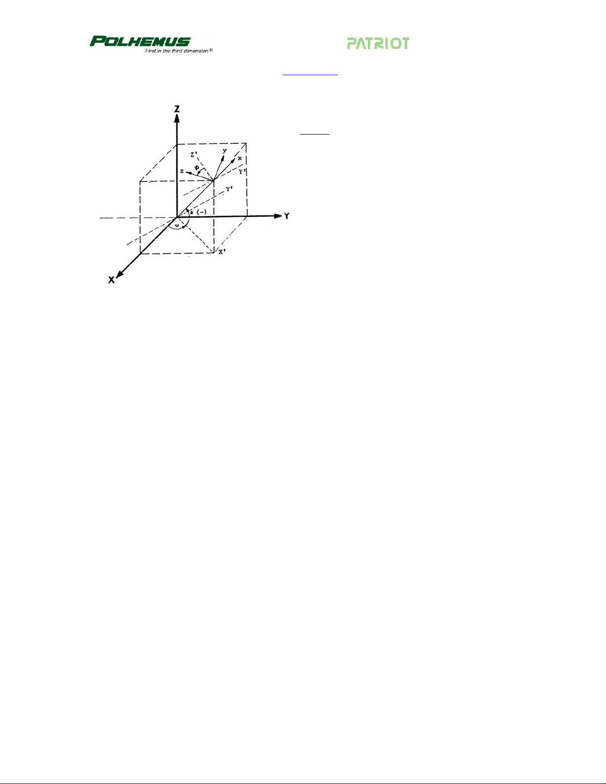
Orientation Angles The azimuth, elevation, and roll angles that define the current
orientation of the sensor coordinate frame with respect to the
designated reference frame.
The Euler angle coordinates that are output by PATRIOT as one
measure of sensor orientation are graphically defined in
1-11
. Here, the x, y, z and X, Y, Z tri-axis arrays represent
Figure
independent, three-dimensional orthogonal coordinate frames. The
x, y, z triad represents the sensor frame in its current orientation
state. The X, Y, Z triad represents the reference frame against
which the relative orientation of the sensor frame is measured. By
definition, the X, Y, Z frame also represents the zero-orientation
reference state of the sensor frame.
The Euler angles, azimuth, elevation and roll, are designated ψ, θ,
and φ. These angles represent an azimuth-primary sequence of
frame rotations that define the current orientation of the sensor
with respect to its zero-orientation state. The defining rotation
sequence is an azimuth rotation followed by an elevation rotation
followed by a roll rotation.
The azimuth angle ψ is defined in the figure as a rotation of the X
and Y reference axes about the Z reference axis. The transition
axes labeled X’ and Y’ represent the orientation of the X and Y
axes after the azimuth rotation.
The elevation angle θ is defined as a rotation of the Z reference
axis and the X’ transition axis about the Y’ transition axis. The
transition axis labeled Z’ represents the orientation of the Z
reference axis after the elevation rotation. The current x-axis of the
current sensor frame represents the orientation of the X’ transition
axis after the elevation rotation.
Lastly, the roll angle φ is defined as a rotation of the Y’ and Z’
transition axes about the x-axis of the sensor frame. The y and zaxes of the current sensor frame represent the orientation of the Y’
and Z’ transition axes after the roll rotation.
Rev. B 14 November 2004
USER MANUAL
In the example of Figure 1-11, the azimuth, elevation and roll
rotations are positive, negative and positive respectively.
Legend
X, Y, Z = Alignment (Reference) Frame
x, y, z = Rotated Stylus or Sensor Coordinate Frame
Ψ = Azimuth
θ = Elevation
φ = Roll
Figure 1-11 Euler Angles
Output List A list of the data items included in a data record.
PATRIOT A two-sensor low cost tracking instrument modeled after
LIBERTY.
P&O Acronym for position and orientation, the six pieces of data needed
to fully describe tracking of an object in 3D space. Some tracking
devices, by virtue of their principle of operation, can produce only
position or only orientation whereas others can produce both P&O
(although the user usually can opt for only those parameters desired).
Pitch Same as elevation.
Quaternion A four-parameter quantity representing a vector and a scalar. The
quaternion q = q
+ i q1 + j q2 + k q3 can be used to represent the
0
sensor’s orientation without the need for trigonometric functions.
The attitude matrix output from PATRIOT can be equivalently
represented by the following matrix using quaternions:
X Directional Cosines Y Directional Cosines Z Directional Cosines
2
2
2
2
⎡
q
0
⎢
⎢
2(
qq
⎢
- q -
q +
q
3
2
1
+
qq
2103
)
2(
q
2
0
-
qq
qq
2
2
- q + q -
q
2
1
⎢
⎢
2(
⎣
-
qq
qq
2( )
+
qq
qq
23012031
2
3
)
2( )
2(
qq
-
qq
2
2
q
1
0
⎤
)
+
qq
20313021
⎥
⎥
)
qq
1032
⎥
⎥
2
2
⎥
+ q - q -
q
3
2
⎦
Rev. B 15 November 2004

USER MANUAL
Response The interval of time between a request to the PATRIOT system to
collect a data point and when that data is available for input from
the PATRIOT system.
Roll Coordinate of orientation tracking about the azimuth-elevation axis
where an increase of the angle is clockwise as viewed from behind or
in the same direction as the object is facing.
SDK
Software Development Kit; software development toolset available
for LIBERTY/PATRIOT-based trackers, consisting of
programming libraries, help files, and sample code. SDK is
sometimes referred to as “API,” although API refers specifically to
the programming libraries used to interface with the instrument.
Sensor The sensor measures the low-frequency magnetic field generated
by the source. The sensor is used to track both the position and
orientation of the object to which it is attached, relative to the
measurement reference frame.
Source The source generates the low-frequency magnetic field measured
by the sensor. The source’s X, Y, and Z-axes are the default
measurement reference frame.
Station The source-sensor pair. PATRIOT supports up to two sensors,
yielding a possible two stations.
Stylus A pencil-shaped housing for the sensor with an integral switch and
used by the operator to indicate and/or select points to be digitized.
Sync Shorthand for synchronization. For example, “sync sign al.”
Units The unit of assumed distance. PATRIOT allows measurement in
either inches or centimeters.
Update Rate The rate at which motion-tracking data can be made available from
the PATRIOT system.
Useful Range The maximum distance at which the resolution and noise
performance of the PATRIOT system can be realized.
Rev. B 16 November 2004

USER MANUAL
User Defaults The values assigned to certain system variables by the user. Stored
in non-volatile memory, the system receives these variable values
at power-up.
XYZ or X, Y, Z The Cartesian coordinates of position tracking where normally +X is
in the forward direction; +Y is in the right hand direction; and +Z is
downward.
XYZAER The output string of data reporting the position, XYZ, and
orientation, AER – azimuth, elevation and roll – of the tracking
sensor.
Yaw Same as azimuth.
<> Used in text to indicate the “Enter” key.
^ Used in text to indicate the “Ctrl” key.
Rev. B 17 November 2004

USER MANUAL
2. PATRIOT System Commands
2.1 Overview
This section specifies the PATRIOT Command Interface. It defines the structure and
function of PATRIOT commands and responses.
The interface is comprised of ASCII commands and binary or ASCII response frames.
The ASCII commands are designed to work in a ‘dumb terminal’ mode, thus keeping the
communications protocol simple and easy to use. These commands are the basis of the
Polhemus APIs.
Additional information is provided in this document to give the reader some background
in the terminology and general science behind the Polhemus tracking technology.
All commands are input on the RS-232 serial port or USB port.
2.2 Command Syntax
2.2.1 Notation
The following notation is used in this manual to describe the PATRIOT command
syntax:
[ ] Items shown inside square brackets are optional. To include
optional items, type only the information inside the brackets. Do
not type the brackets.
<> Represents an ASCII carriage return or “enter” (‘^M’, 0x0d).
Whenever shown this value must be present to terminate the
command sequence.
... An ellipsis indicates that you can repeat an item.
, A comma represents a delimiter in a list of optional parameters.
The comma must be present for those parameters which are
omitted except for the case of trailing commas. For example:
Qs,p1,,,p4<>
is the proper command format when omitting parameters p2 and
p3. Commas following the parameter p4 are not required if
parameters p5 and p6 are omitted.
| A vertical bar means either/or. Choose one of the separated items
and type it as part of the command. For example,
“ON|OFF” indicates that you should enter either ON or OFF, but
not both. Do not enter the vertical bar.
Rev. B 18 November 2004

USER MANUAL
^ A caret in front of a command letter indicates that the control key
should be held down while typing the command letter. Control
commands produce ASCII values between 0x00 and 0x1F.
For discussion purposes, examples assume that only one sensor is used, in the Sensor 1
position.
2.2.2 Command Format Notes
• Commands and alphabetic parameters are NOT case sensitive.
• Commands that use optional parameters use current system retained values for
parameters omitted from the command.
• The term “station” refers to a source-sensor pair. For example, eight sensors paired
with the one available source are assigned station numbers one through eight (1-8).
• Unless otherwise noted, commands do not take any punctuation immediately
following the command letter. However, if an optional first parameter is to be
omitted, a comma is necessary between the command letter and the next parameter.
• A numeric floating point value will be accepted by the machine if any of the
following formats are used. For example, 3.0 may be specified as: 3, 3., 3.0 or
3.0E+00.
Station Wildcard
When using a command that requires a station number as the parameter, the user may
wish to apply the command to both stations of the PATRIOT system. In such situations a
‘*’ character may be used in place of the station number to apply the settings to both
stations in the PATRIOT system.
e.g. H*,0,0,1<> would change the hemisphere for every station to the positive Z
hemisphere.
e.g. H1,0,0,1<> would change the hemisphere for only station 1 to the positive Z
hemisphere.
Default Parameters
Commands that take multiple parameters can be used to change a subset of the
parameters and leave the remaining parameter values unchanged.
For example:
• The command Gaz,el,roll<> changes the source mounting frame to (az, el, roll).
• The command G0,180,0<> changes the source mounting frame to (0,180,0). By
omitting the el parameter from the command: G0,,180<> the source mounting fram e
would then change to (0,180,180). The el setting remains unchanged.
Rev. B 19 November 2004

USER MANUAL
• Similarly, the az parameter can be defaulted by: Gel,roll<> and the roll parameter
can be defaulted by Gaz,el<>. The trailing comma is not required when the last
parameter(s) are omitted.
2.2.3 Response Format Notes
Depending on the
‘F’ – Output Format configuration setting (see page 30), frames
received from PATRIOT in response to the commands detailed in this document will
conform to one of the following format definitions.
ASCII
ASCII response frames are described in this document using the following notation:
A............... Is an ASCII Character
B .............. Is a Blank or Space
S .............. Is the Sign byte (+,- or a space for (+))
x ............... Is a decimal digit (0-9)
<>.............Carriage Return + Line Feed (i.e. ^M^J, 0x0d 0x0a)
n() ............ Repeat contents of parentheses n times
Example: A format 3(Sx.xxxxB), would be output as: -1.1111 2.2222 -3.3333
Except where noted, ASCII mode response includes a standard 5-character response
header. The default ASCII response frame format is as follows:
Table 2-1 ASCII Response Format
Byte Index Format Description
0 A First Digit of Station Number
1 A Second Digit of Station Number
2 A Command Letter
3 A Error Indicator
HEADER
4 B ASCII Blank character
5 thru n A Response Body
n+1, n+2 <> A P&O response frame may not contain a
Carriage Return/Line Feed as specified by
the user with the ‘O’ command
If the Station Number is not applicable to the command, the first two fields will be ASCII
zeros ‘0’.
Error codes presented in the Error Indicator field are detailed in
PATRIOT Error Code
Summary on page 23. “No Error” is represented by an ASCII blank character ‘ ‘.
Binary
Binary response frames are described in this document using the following notation:
US ............unsigned short, 16 bits
SH ............signed short, 16 bits
UC............unsigned char, 8 bits
Rev. B 20 November 2004

USER MANUAL
CH............char, 8 bits
I................signed integer, 32 bits
DW...........unsigned double word, 32 bits
FL.............32-bit single-precision floating-point in IEEE format consisting
of sign bit, 8-bit exponent, and 23-bit mantissa:
SXXX XXXX XMMM MMMM MMMM MMMM MMMM MMMM
[n].............Array of size n of type preceding square brackets (e.g. FL[3])
Binary response frames are composed of an 8 byte frame header followed by a variablelength frame body as follows:
Table 2-2 Binary Response Format
Byte Index TYPE Description
0,1 US Frame Tag, always ‘PA’ or 0x5041 for PATRIOT HST
2 UC Station Number
3 UC Initiating command
4 UC Error Indicator
HEADER
5 UC Reserved
6,7 SH Response size; number of bytes in the response body
8 - n Binary Response body
Error codes presented in the Error Indicator field are detailed in
PATRIOT Error Code
Summary on page 23. “No Error” is represented by NULL (0x00).
Error Responses
When in binary mode, error responses are always prepended by the binary frame header,
followed by the ASCII error string. In ASCII mode, error responses have no header. See
PATRIOT Error Code Summary on page 23 for a complete listing of error responses.
Rev. B 21 November 2004

USER MANUAL
2.3 PATRIOT User Command Set Summary
Command Description Decimal Hexadecimal Notes Page
A Alignment Reference Frame 65 0x41
B Boresight 66 0x42 28
C Continuous Print Output 67 0x43 62
F Output Format 70 0x46 0=asc, 1=bin 30
G Source Mounting Frame 71 0x47 32
H Hemisphere of Operation 72 0x48 34
L Stylus Button Function 76 0x4C 37
N Tip Offsets 78 0x4E 39
O Output Data List 79 0x4F 41
P Single Data Record Output 80 0x50 63
25
Q FrameCount/Timestamp Reset 81 0x51 0=both;1=FC,2=TS 65
U Set Units 85 0x55 0=in, 1=cm 43
X Position Filter Parameters 88 0x58 45
Y Attitude Filter Parameters 89 0x59 48
^B UN-Boresight 2 0x02 51
^E Set Echo Mode 5 0x05 0=off, 1=on 52
^K Save Operational Configuration 11 0x0B 66
^O RS-232 Port Configuration 15 0x0F 53
^R Reset Alignment Frame 18 0x12 55
^T Built-in-Test Information 20 0x14 67
^U Active Station State 21 0x15 56
^V WhoAmI (Software versions) 22 0x16 69
^W Set Operational Configuration 23 0x17 71
^X Operational Configuration ID 24 0x18 59
^Y Initialize System 25 0x19 72
^Z Read Operational Configuration 26 0x1A 73
Rev. B 22 November 2004
 Loading...