

Page 1

Star★★★★Trak User Guide v001B
Table of Contents
1 First Things First 1-1
1.1 Copyright...................................................................................1-1
1.2 Reader’s Guide and Glossary...................................................1-1
1.3 Warning.....................................................................................1-2
1.4 Customer Service .....................................................................1-2
2 System Specifications 2-3
2.1 StarTrak System Specifications................................................2-3
Environment ....................................................................2-3
Receivers ........................................................................2-3
TrakBelt...........................................................................2-3
Operating Modes.............................................................2-3
Battery Time - Wireless...................................................2-4
Update Rate ....................................................................2-4
Client Interface ................................................................2-4
Transmitters ....................................................................2-4
Absolute Accuracy...........................................................2-4
Repeatability....................................................................2-4
Range..............................................................................2-4
Measurement Limits........................................................2-5
Operating Temperature...................................................2-5
Physical Characteristics ..................................................2-5
3 StarTrak System Description and Components 3 -6
3.1 Introduction ...............................................................................3-6
3.2 Detailed Component Descriptions ............................................3-7
Battery Pack.......................................................................3-7
Battery Charger..................................................................3-8
Calibration System .............................................................3-9
Ethernet Cables................................................................3-10
Keyboard, Monitor, and Mouse ........................................3-11
StarServe..........................................................................3-12
Standard Receiver and Cable Assembly .........................3-13
StarPak.............................................................................3-14
StarLink RF Interface .......................................................3-16
Long Ranger Transmitter .................................................3-18
Tether Cable.....................................................................3-19
TrakBelt............................................................................3-19
StarDrive...........................................................................3-20
4 Step-By-Step System Installation 4-21
4.1 Connecting it all together........................................................4-21
Overview...........................................................................4-21
StarServe..........................................................................4-22
Mouse............................................................................4-22
Keyboard.......................................................................4-22
Monitor ..........................................................................4-22
StarLink RF Interface Unit................................................4-22
StarDrive...........................................................................4-22
Long Ranger Transmitter Assembly.................................4-23
Transmitter Mounting .......................................................4-24
i
Page 2

Star★★★★Trak User Guide v001B
System Interconnect.........................................................4-27
Layout Considerations ..................................................4-28
StarTrak Component Interconnect................................4-29
Receivers..........................................................................4-35
TrakBelt............................................................................4-37
Ethernet Connection.........................................................4-37
4.2 Starting up StarTrak................................................................4-38
Start the Server ................................................................4-38
Launch the StarTrak Application......................................4-38
Start the MAC...................................................................4-38
Power up StarPack...........................................................4-39
Verify Active Sensors .......................................................4-39
Examine Sensor Characterization and Calibration Data..4-40
Display Field Data ............................................................4-41
Display Motion Data .........................................................4-42
Stopping StarTrak ............................................................4-42
4.3 Environment Model.................................................................4-43
Before you Begin Using Data...........................................4-43
Required Equipment .........................................................4-43
Setting Up.........................................................................4-44
Introduction....................................................................4-44
Hardware Configuration ................................................4-44
Software Configuration and Operational Setup ............4-46
Transmitter Location, Orientation and Hemisphere ......4-47
Define the Mapping Grid ...............................................4-47
Data Collection.................................................................4-48
Map Setup.....................................................................4-48
Mapping Process...........................................................4-49
Apply Area Compensation File......................................4-51
5 System Operation 5-53
5.1 Introduction .............................................................................5-53
StarTrak Performer...........................................................5-53
StarTrak Operator ............................................................5-53
5.2 StarTrak Main Window............................................................5-53
Introduction.......................................................................5-53
Main Window Controls .....................................................5-54
Menu Bar.......................................................................5-54
Tool Bar.........................................................................5-55
Status Bar......................................................................5-55
File Menu..........................................................................5-55
View Menu........................................................................5-55
Error Logging....................................................................5-56
Window Menu...................................................................5-56
Help Menu........................................................................5-56
About StarTrak .................................................................5-57
5.3 Status Window........................................................................5-57
Introduction.......................................................................5-57
Channel Status Messages ...............................................5-58
Channel Message Rate....................................................5-59
Channel Sensors View.....................................................5-60
Control Buttons.................................................................5-60
Start...............................................................................5-60
Reset.............................................................................5-60
Sync...............................................................................5-61
5.4 Data Views..............................................................................5-61
ii
Page 3

Star★★★★Trak User Guide v001B
Data Menu........................................................................5-61
Motion Data......................................................................5-62
Motion View......................................................................5-63
5.5 Diagnostic Views.....................................................................5-64
Diagnostics Menu.............................................................5-64
Magnetic Field Data .........................................................5-64
Characterization Data.......................................................5-65
Calibration Data................................................................5-66
5.6 Tools .......................................................................................5-66
Tools Menu.......................................................................5-66
Reset Algorithm................................................................5-67
Calibration and Mapping ..................................................5-67
Introduction....................................................................5-67
Map Area.......................................................................5-68
Pole Setup.....................................................................5-69
Relative Position............................................................5-69
Map Collection...............................................................5-70
Options Window...............................................................5-71
Introduction....................................................................5-71
File Locations Tab.........................................................5-72
Network Tab..................................................................5-73
Dipole Tab.....................................................................5-74
Area Model..........................................................................5-74
Filter ....................................................................................5-75
Hemisphere.........................................................................5-75
RF Link Tab...................................................................5-76
Format Tab....................................................................5-77
6 Exporting Data 6-78
6.1 Introduction .............................................................................6-78
6.2 Data Format............................................................................6-78
7 Maintenance 7-81
7.1 Introduction .............................................................................7-81
7.2 Maintaining a Safe Work Environment ..................................7-81
7.3 Caring for your StarTrak System ............................................7-81
7.4 Transporting the StarTrak System..........................................7-81
8 Technical Support 8-83
8.1 Technical Support...................................................................8-83
9 Important Information 9-84
9.1 Warranty & Liability.................................................................9-84
9.2 Indemnity Against Patent Infringement...................................9-85
9.3 FCC Statement .......................................................................9-85
iii
Page 4

1 First Things First
Star★★★★Trak User Guide v001B
1.1 C
Copyright ©1998 by Polhemus Incorporated
Colchester, Vermont U.S.A.
All rights reserv ed. No p art of this public atio n m ay be rep rod uced, s tor ed in a r etrieva l s yst em ,
or transmitted, in any form or by any means, mechanical, photocopying, recording or
otherwise, without the prior writte n permission of Polhem us Incorporated. No pate nt liability is
assumed with respect to the use of the inform ation contained herein. While e very precaution
has been taken in the preparation of this book, Polhemus Incorporated assumes no
responsibility for errors or omissions. Neither is any liability assumed for damages resulting
from the use of the information contained herein.
STAR★TRAK® is a registered trademark of Polhemus Incorporated.
1.2 R
Throughout this m anual, the f ollowing c onvent ions are us ed. W ords s urrounded b y “<” and “>”
represent keys on your StarT rak s ystem keyboard. F or exam ple, the c ontrol ke y is pri nted lik e
this
<Ctrl>
OPYRIGHT
EADER’S GUIDE AND GLOSSARY
When groups of keys should be pressed and held they are printed like this:
<Ctrl> + <Alt> + <Del >
When prompts and m essages appear on the sc reen or commands that are to be typed, they
appear in a different typeface. For example:
All Sensors Active
Throughout this manual, the wor d “ rec ei ver” is us e d synonymously with the word “ sens or .” The
terms are used interchangeably to refer to the miniature antennae that are placed on the object
to be tracked.
First Things First 1-1
Page 5

Star★★★★Trak User Guide v001B
1.3 W
Before operating your StarTrak system, make cer tain that the StarServe, StarDrive U nit and
the monitor are properly grounded by connection to three-terminal grounded power
receptacles.
The voltages deve lop ed in the optional Su perNo va transmitter(s) can be h igh eno ugh to create
a shock hazard. Do not t ouch, handle or place conduc tive material near these units while in
operation.
DO NOT connect or disconnect the Long Ranger or SuperNova transmitter(s) to/from the
StarDrive Unit when powered, as this will cause severe damage to both StarTrak components.
1.4 C
ARNING
Warning, Shock Hazard !!!
USTOMER SERVICE
If problems are encoun tered with the StarT rak equipment, help is just a telephon e call away.
Call Polhemus and ask for Customer Service. For the most part, our Customer Service
engineers can handle your prob lems over the telephone and get you bac k into the fast lane
right away. If the prob lem requires repair of your instrument, the Customer Serv ice engineer
will issue a Return Merchandise Author ization (RMA) number. It is a good idea to keep the
original shipping co ntainer for your StarTrak instrument in the event t hat the instrument m ay
require repair. Please do not retur n any instrument without an RMA number as it will not be
accepted. If your instrument is still under warranty, Polhemus will repair it free of charge
according to the provisions of the warrant y as stated in Sec tion 9 of th is doc um ent. The pr oper
return address is:
Polhemus Incorporated
1 Hercules Dri ve
Colchester, Vermont 05446
Attention: RMA # ______
Telephone (Voice): (802) 655-3159
Telephone (Voice): (800) 357-4777
Telephone (FAX): (802) 655-14 39
First Things First1-2
Page 6

2 System Specifications
Star★★★★Trak User Guide v001B
2.1 S
TARTRAK SYSTEM SPECIFICATIONS
Environment
Operating volum e no larger t han a 12f t. (3.6 m ) radius. T he enviro nment m ust be calibrat ed in
order to provide spec ified per form ance. Spec ified per form ance will be pr ovided i n this volum e,
with somewhat degraded performance outside that central volume. Minimum separation
(transmitter center to receiver distance) is 1.5 ft. (0.5 m). Use of the optional Super Nova
transmitter extends the maxim um specified perform ance range to 18 ft. (5.5 m ) and minimum
separation to 5 ft. (1.5 m).
Receivers
Up to 16 Receivers on each of 2 actors, for a total of 32 Receivers.
TrakBelt
One per actor, for a total of 2. Conta ins the elec tronics assem blies to acq uire rec eiver signa ls,
digitize and format data, and transmit to StarServe. Belts are powered by rechargeable
batteries, which also are housed in the be lt. Provisions are m ade for operation with either one
or two batteries.
Operating Modes
Wireless Mode: No cables will connect actor s with servers . Actor s' m otions wi ll be c aptured for
a period of time limited by the TrakBelt’s battery capacity.
Tethered Mode: A thi n, 1/ 4 i n. cab le connecting each ac tor with the St arTrak Motion Capture
Server will allow capture of actors' m otions for long periods of time: 1 hour, 1 batter y; 2 hour s ,
2 batteries; 16 receivers.
System Specifications 2-3
Page 7

Star★★★★Trak User Guide v001B
Battery Time - Wireless
At least 90 minutes, two batteries and 16 receivers.
Update Rate
120 Hz. per Receiver, independent of the number of receivers.
Client Interface
Ethernet, UDP Protocol
Transmitters
An arrangement of transmitting antennas sufficient to provide the performance specified
herein. The Long Ranger is supplied standard. The Super Nova is optional and can extend the
operating range, usually by 30% - 40%.
Absolute Accuracy
The absolute dim ensional accuracy of the position and or ientation reported by each Rec eiver
in the Calibrated Volume.
Position: 1 in. (2.5 cm) mean value over 100 samples. Standard deviat ion of 0.4 in. (1
cm)
Orientation: 1° (2.5 cm) peak
Repeatability
Within system accuracy,
Position: 0.5 in. (1.3 cm)
Orientation: 2°
Range
With Long Ranger Transmitter: 1.5 ft. (0.5 m) to 12 ft. (3.6 m) radius
With Super Nova Transmitter: 5 ft. (1.6 m) to 18 ft. (5.5 m) radius
NOTE: Operation in a distortion-free environment with the Super Nova requires calibration.
This may not be necessary with the Long Ranger.
System Specifications2-4
Page 8

Measurement Limits
Six degree-of-freedom sensing. No line-of-sight limits.
Operating Temperature
10°C-40°C at 10%-90% RH, non-condensing
Physical Ch a racteristics
Star★★★★Trak User Guide v001B
Motion Capture Server --
Configuration: Tower
Size: 16.5” (41.9 cm) L x 7.25” (18.4 cm) W x 17.5” (44.4 cm) H
Weight: 61 lbs.
Receiver
Size: Approximately 1.19” (30 mm) x .75” (19 mm) x .75 (19 mm)
Weight: 1.0 oz. (30 g)
Transmitter Driver –
Configuration: Mini-tower
Size: 14.25” (36.2 cm) L x 7.5” (19 cm) W x 14.5” (36.8 cm) H
Weight: 17 lbs.
TrakBelt
Configuration: Cloth belt with pocket for 1 StarPak electronics module and two batteries
StarServe
StarDrive
Available Sizes: Small (33.25” x 8”); Medium (40” x 8”); Large (49” x 8”)
StarPak
Size: 6” (15.2 cm) x 6” (15.2 cm) x 2.5” (6.4 cm)
Weight: 4.5 lbs. with 16 receiver ports and wireless link.
StarLink
Size: 11” (27.9 cm) L (incl. antennas) x 5.5” (14 cm) W x 1.5” (3.8 cm) H
Weight: 1.5 lbs. (with dual units)
System Specifications 2-5
Page 9

Star★★★★Trak User Guide v001B
3 StarTrak System Description and Components
3.1 I
The overall StarTrak system interconnect encompasses the following main components:
StarServe – The central control unit for the StarTrak system. Part number 4A0436-01.
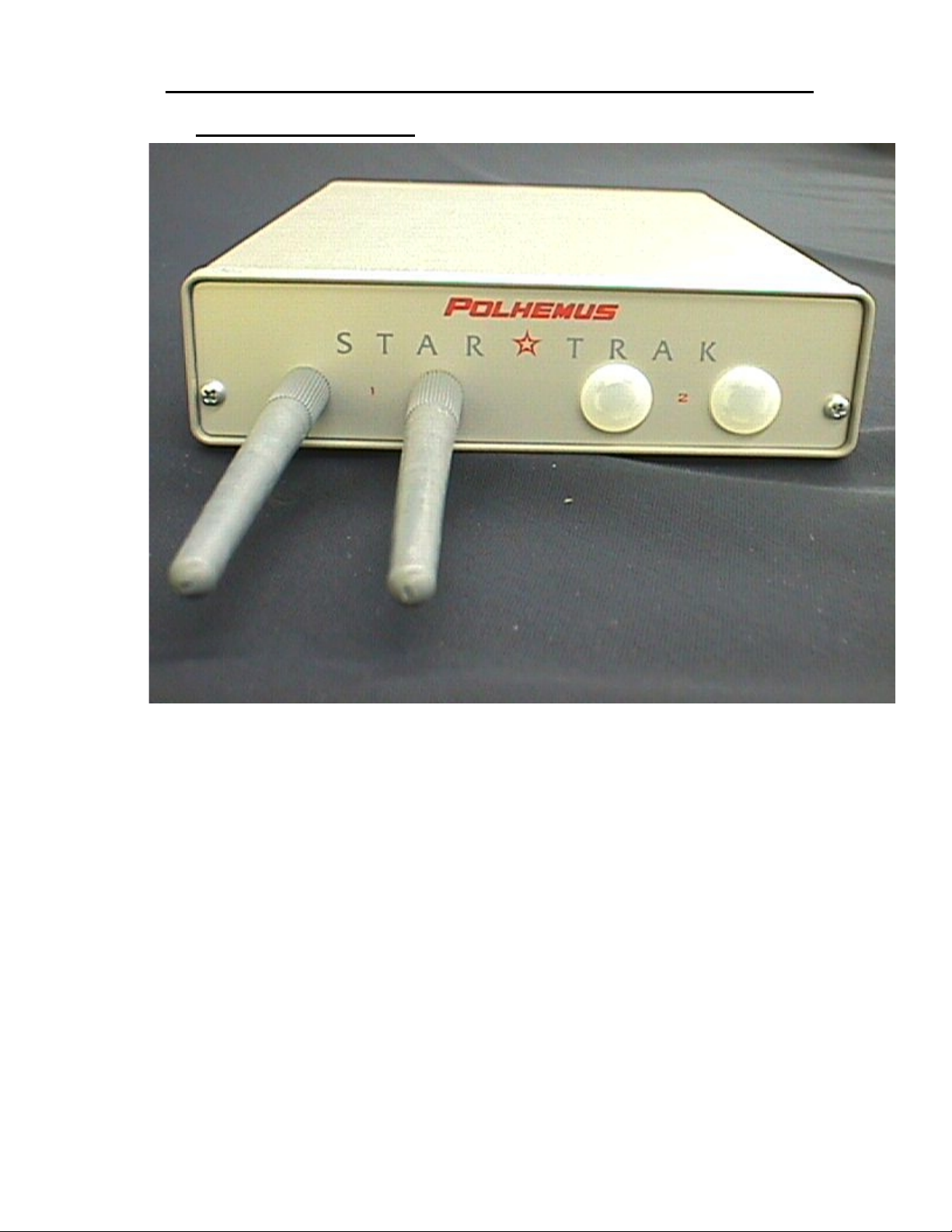
StarLink RF Interface – A Spread Spectrum radio transmitter and interface unit used to
communicate with the StarPack Assemblies. Two different configur ations are available: Part
number 4A0438-01 for a 1-actor RF wireless unit or 4A0438–02 for a 2-actor wireless unit.
Calibration Fixture – The StarTrak environment calibration pole system. Part number
4A0443-01.
Long Ranger Transmitter – An apparatus that creates a lo w-level magnetic fiel d throughout
the motion capture volume. Part number 4A0345-02.
StarDrive Unit – An electronics unit that receives low power signals and amplifies them to
drive the transmitter. Part number 4A0426-01.
Receiver – A miniature antenna, placed on the object to be tracked that receives the
transmitted magnetic fields. StarTrak can simultaneously operate up to 32 receivers per
system. Three different cable length configurations are available: Part number 4A0434-01,
4A0434-02, and 4A0434-03.
StarPak – Synchronizes the sensing of the magnetic fields, collects sensed data, converts
data to digital form and transm its data via t eth er or wir eles s to the StarLink. Two confi gurat ions
are available: An 8-input unit is part number 4A0435-01 and a 16-input unit is 4A0435-02.
NTRODUCTION
StarLink – Provides the wireless link to/from the StarPak (s) and interfaces the StarServe via
its internally housed special MAC board. Part number 3A0602.
Host Computer – The system utilizing the StarTr ak motion capture data. The da ta is r eceived
via the Ethernet connection.
The remainder of th is chapter will describe all of the StarTrak components in detail. P lease
check to ensure that you have received all of the StarTrak components listed in this manual.
StarTrak System Description and Components3-6
Page 10
Star★★★★Trak User Guide v001B
3.2 D
Battery Pack
ETAILED COMPONENT DESCRIPTIONS
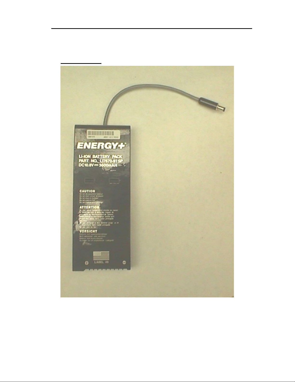
Figure 3-1 Battery Pack
The StarTrak Battery Pack consists of a long-life Lithium Ion battery capable of powering a
single StarPak for approxim ately 1 hour between charges. One b attery pack will operate up to
16 receivers.
StarTrak System Description and Components 3-7
Page 11
Star★★★★Trak User Guide v001B
Battery Charger
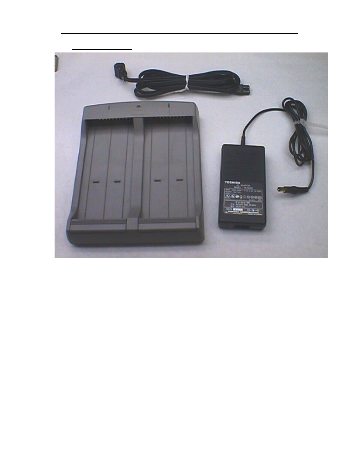
Figure 3-2 Battery Charging Unit
The battery charger un it is pr ovid ed t o charg e the L ithium Ion batter y pack . T he charge tim e is
approximately 1.5 hours.
StarTrak System Description and Components3-8
Page 12
Calibration System
Star★★★★Trak User Guide v001B
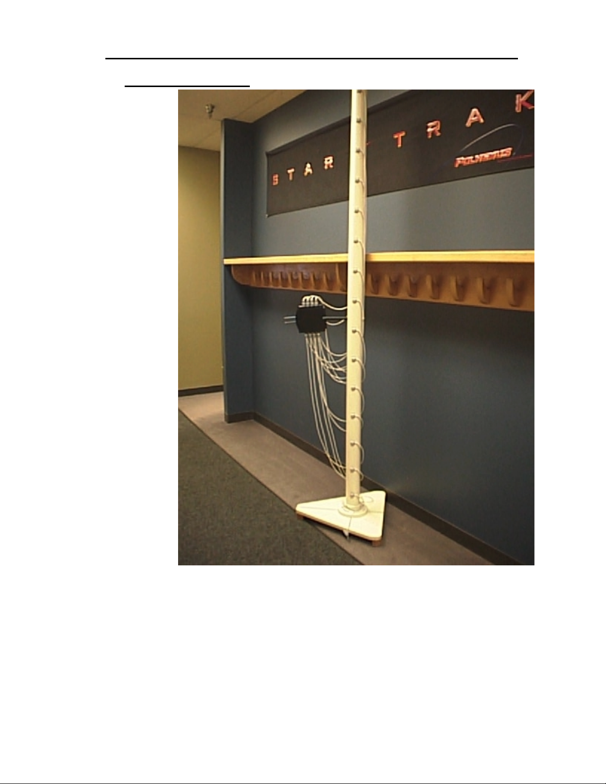
Figure 3-3 Calibration fixture
The StarTrak ca libration fixture c onsists of a m odular pole where the calibration receivers are
mounted in a known position an d orienta tion. This fixture is used to m odel th e environm ent for
the motion capture space.
StarTrak System Description and Components 3-9
Page 13
Star★★★★Trak User Guide v001B
Ethernet Cables
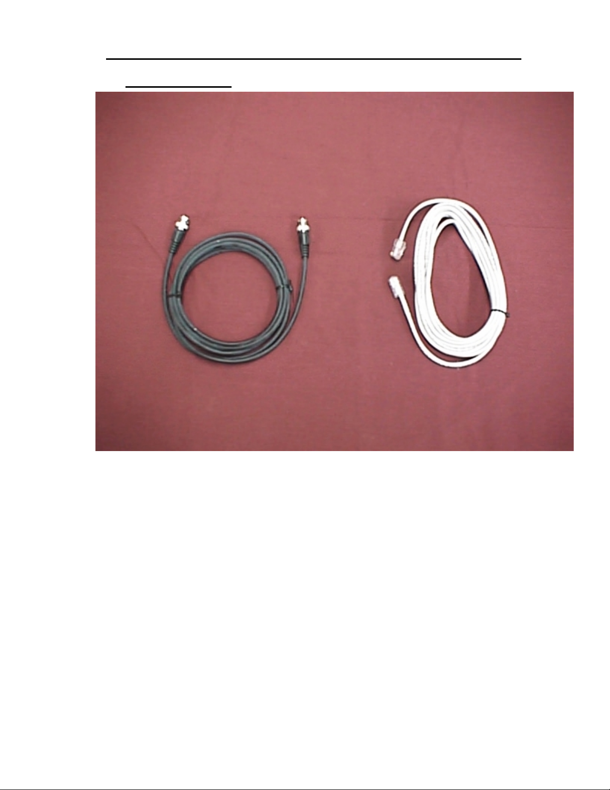
Figure 3-4 10Base2 (left) and 10BaseT (right) Ethernet Cables
The Ethernet cables pro vide a high-speed data pipe to external data proc essing equipment.
Both Real Time and recorded motion capture data may be transmitted over this link.
StarTrak System Description and Components3-10
Page 14
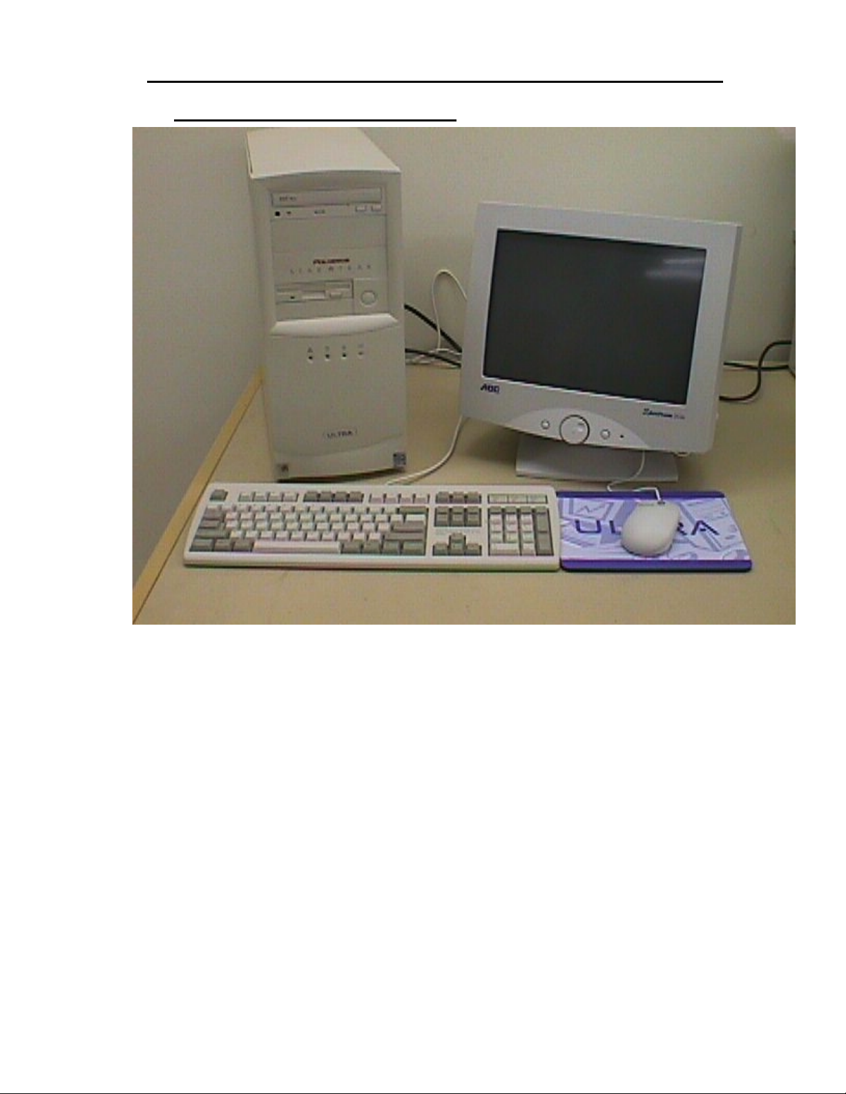
Keyboard, Monitor, and Mouse
Star★★★★Trak User Guide v001B
Figure 3-5 StarServe, Keyboard, Monitor and Mouse
The keyboard, monitor and mouse provide a means for interfacing with the StarTrak system.
StarTrak System Description and Components 3-11
Page 15

Star★★★★Trak User Guide v001B
StarServe
Figure 3-6 StarServe
The StarServe is the central cont rol unit of the St arTrak system. It is built upo n a W indows NT
platform and performs numerous functions in addition to providing real-time motion capture
data. A few key functions are described here:
Position & Orientation Solution – The Server performs the sophisticated position and
orientation calculations.
MAC Board – Installed in the StarServe is a special circuit board that performs two functions:
StarTrak System Description and Components3-12
Page 16
Star★★★★Trak User Guide v001B
1. StarDrive Excitation – The Server provides the unique wa vef or m that is amplified by
the Star Drive unit and then applied to the Long Ranger Transmitter.
2. StarPak Control and Data Acquisition – Used to com municate with the per form ers’
StarPak via tether cable and via Radio Link with the StarLink RF interface.
Network Connection – The server provides an Ethernet interface to your host computer.
Standard Receiver and Cable Assembly
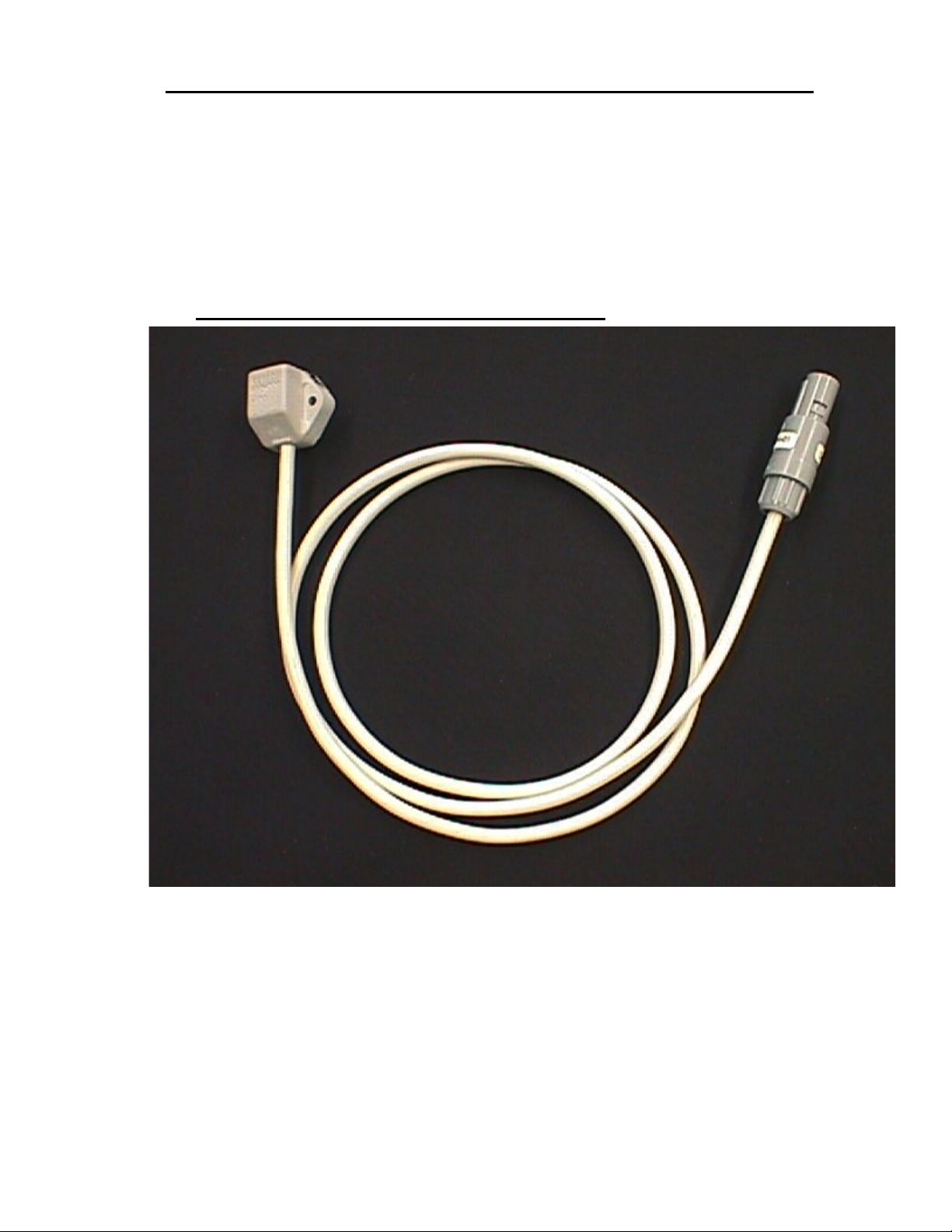
Figure 3-7 Standard Receiver and Cable Assembly
A StarTrak rec eiver is a miniature antenna, placed on the object to be tr acked, that recei ves
the transmitted m agnetic fields. The StarTrak can simultaneously operate up to 32 receivers
per system. The r eceiver’s small size provides both comfort and good fit. Up to 16 receivers
can be connected to a single StarPak. See figure 3-7 above.
Receivers may also be referred to as “sensors” in this document.
StarTrak System Description and Components 3-13
Page 17
Star★★★★Trak User Guide v001B
StarPak
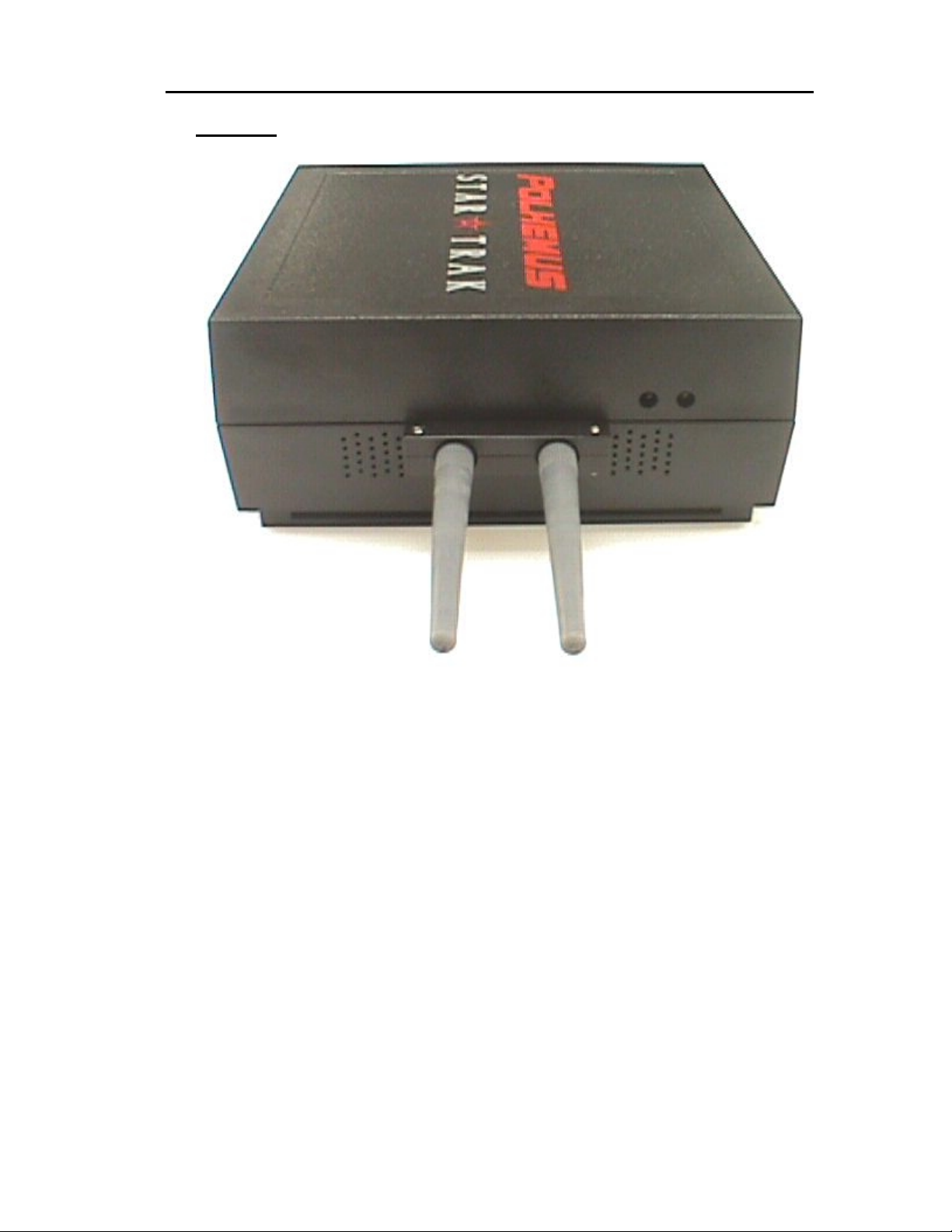
Figure 3-8 StarPak Front View
StarTrak System Description and Components3-14
Page 18
Star★★★★Trak User Guide v001B
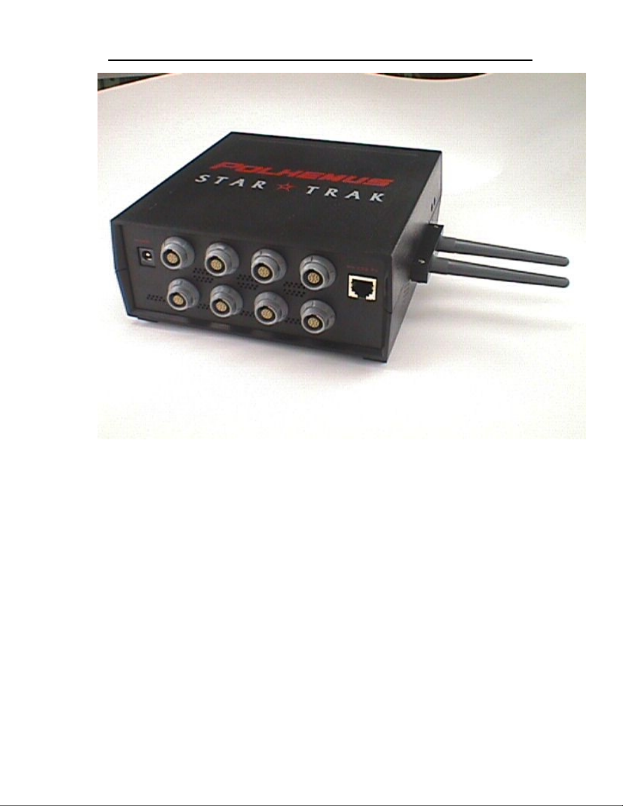
Figure 3-9 StarPak Back View
The StarPak is the interface between the 16 Receivers and the StarLink RF Interface. The
StarPak performs primary signal processing of the data provided by the Receivers,
conditioning it and getting it into digital format ready for transmission to the server.
StarTrak System Description and Components 3-15
Page 19
Star★★★★Trak User Guide v001B
StarLink RF Interface
Figure 3-10 StarLink Front View
StarTrak System Description and Components3-16
Page 20
Star★★★★Trak User Guide v001B
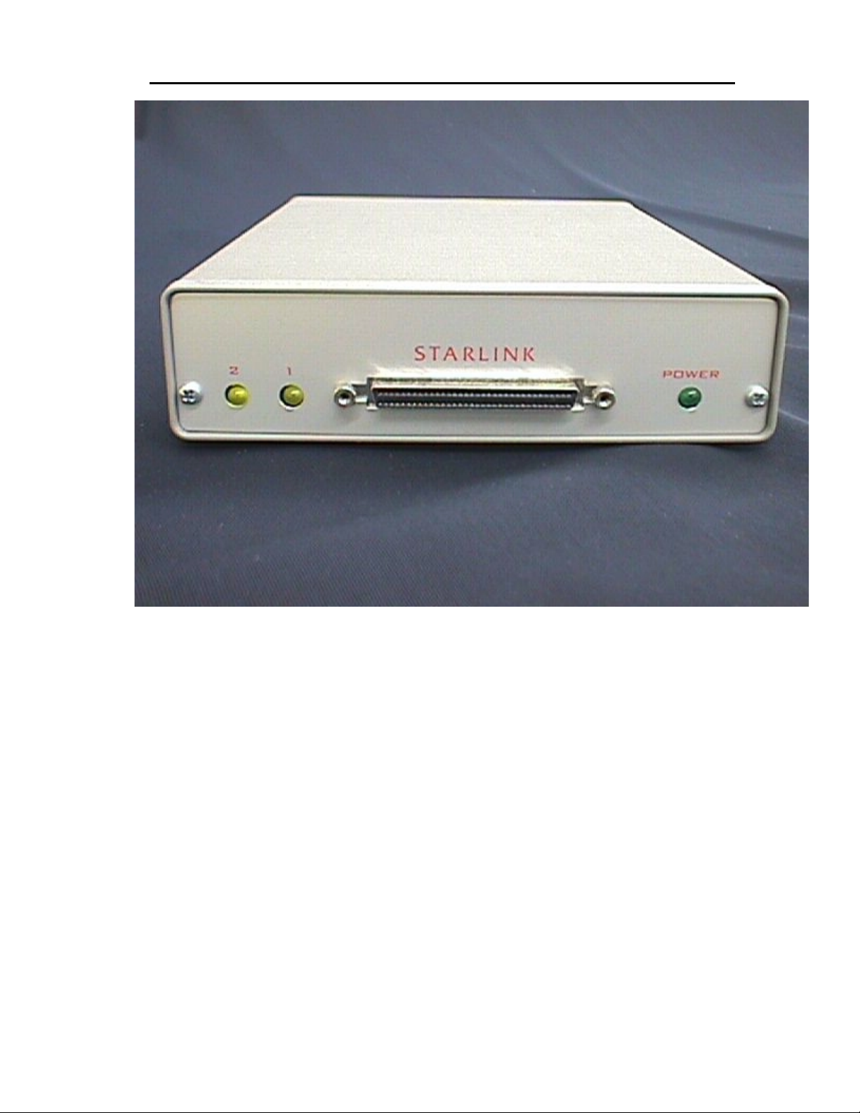
Figure 3-11 StarLink Rear View
The StarLink RF unit interfaces the Spread Spectrum RF transceivers to the StarSer ve. The
transceivers provide the wireless data link between the StarServe and the StarPak. The
StarLink RF Interface can support communication for one or two StarPaks.
StarTrak System Description and Components 3-17
Page 21
Star★★★★Trak User Guide v001B
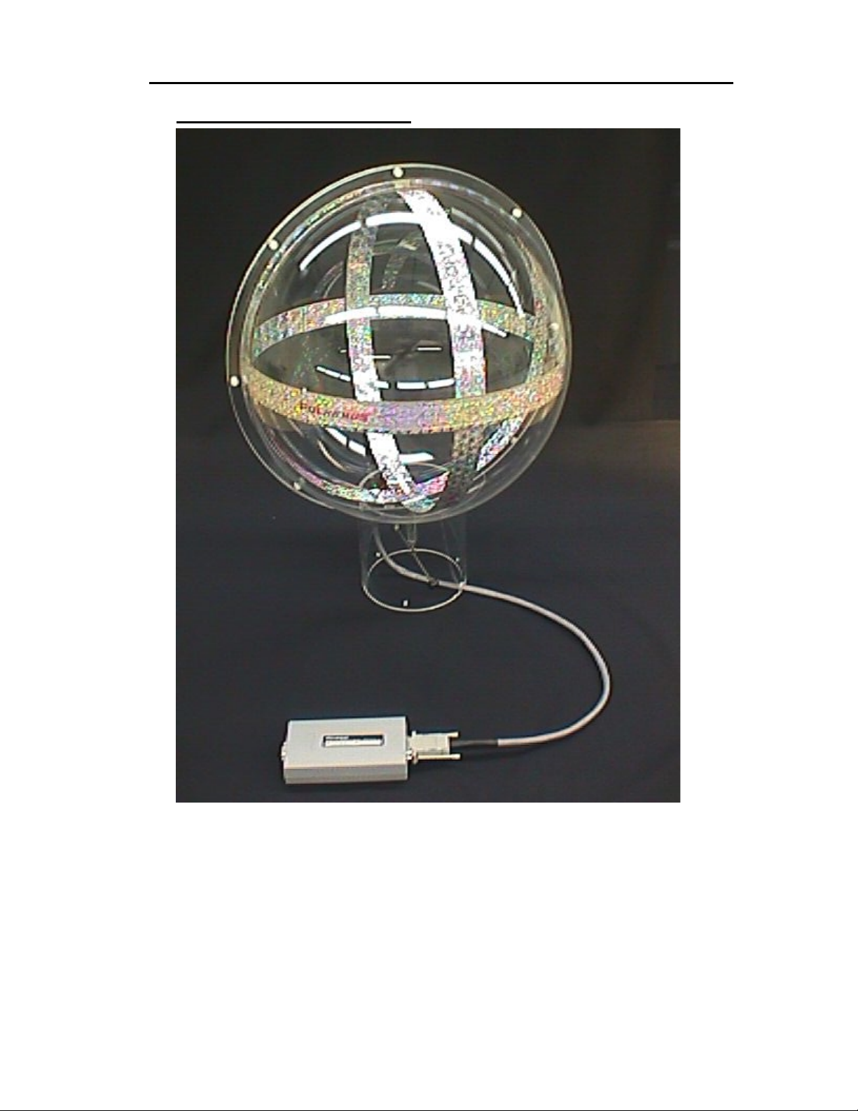
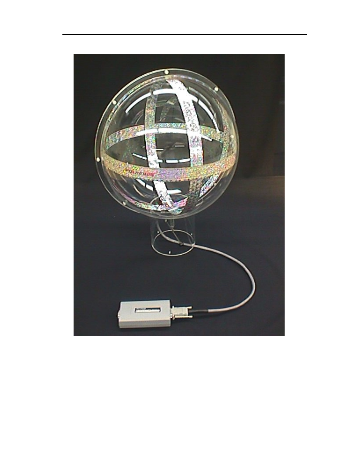
Long Ranger Transmitter
Figure 3-22 Long Ranger Transmitter System with Tuning Module
The Long Ranger T ransmitter is the “ Antenna” or m agnetic radiator of the Star Trak s ystem. It
must be placed on a stable platform and oriented in a specific direction.
Warning: Do not attach/remove the Long Ranger Transmitter to/from the Star Drive Unit when
it is powered on or it will cause severe damage to both units.
StarTrak System Description and Components3-18
Page 22

Star★★★★Trak User Guide v001B
Tether Cable
The Tether Cable is a c ondu it through which all the c o llected Receiver data may be sent to the
StarTrak StarServe f or position and orientation proc essing. In non-wireless m ode the Tether
remains connected to the performer. In wireless mode, the Tether is used only to initially
synchronize the StarPak with the StarServe. There exists one Tether per StarPak unit.
TrakBelt
Figure 3-33 TRAKBELT
The TRAKBELT is a simple har ness worn aro und the per form er’s waist t hat prov ides for easy
attachment of the StarPak and Battery Pack to the performer.
StarTrak System Description and Components 3-19
Page 23
Star★★★★Trak User Guide v001B
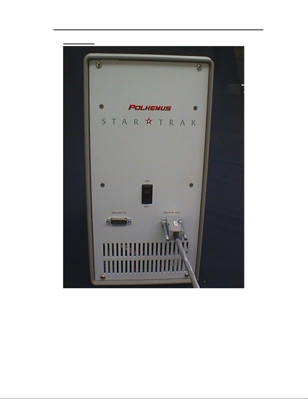
StarDrive
Figure 3 44 StarDrive
The StarDrive unit receives low power signals and amplifies them to drive the transmitter.
StarTrak System Description and Components3-20
Page 24

Star★★★★Trak User Guide v001B
4 Step-By-Step System Installation
4.1 C
ONNECTING IT ALL TOGETHER
Overview
Figure 4-1 illustrates the overall electrical interconnect of the StarTrak system.
POLHEMUS
STARTRAK
KEY BOARD
MOUSE
115/230 VAC
17500 BLK/ 17850
MONITOR
STAR
LINK
AB
PCMCIA PCMCIA
CABLE ASSY
DCA2775/MD68MM10
STAR SERVER
4A0436-01
EXTENDER BRD
MAC BOARD
8 STAR TRAK
RECEIVERS
INTERCONNECT
STAR DRIVE
4A0426-01
2A0596-01
BATTERY PACK BATTERY PACK
CABLE
TETHER
A3L79b10BL-MW
115/230 VAC
17500 BLK/
17850
CABLE ASSY
3A0542-03
STAR PACK
MASTER BOARD
SLAVE BOARD
PCMCIA
STAR TUNER
3A0583-01
2A0497-022A0497-02
LONG RANGER
3A0345-02
CABLE ASSYCABLE ASSY
3A0581-01
8 STAR TRAK
RECEIVERS
4A0434-0*4A0434-0*
Step-By-Step System Installat io n 4-21
Page 25

Star★★★★Trak User Guide v001B
StarServe
The StarTrak StarServe is a Pentium based, Microsoft NT workstation running the StarTrak
motion capture appl ication. The ser ver unit is comprised of the chassis, k eyboard, m ouse and
monitor. The chassis contains the receptacles for the other server components, the MAC
board and an Ethernet interface.
Mouse
The mouse is installed at the server chassis into a PS2 mini-DIN receptacle. All required
mouse drivers are pre-installed at the factory.
Keyboard
The keyboard is a standard AT style input device. It is connected at the rear of the server
chassis into a PS2 mini-DIN receptacle.
Monitor
The monitor is connected to the receptacle at the rear of the StarServe chassis with a standard
video cable. Refer to Figure 3-5. The monitor power cord must be attached to a standard
power receptacle. The monitor and chassis automatically operate at the proper voltage 100220V, 50-60Hz, depending on what is supplied.
StarLink RF Interface Unit
This unit interfaces the Spread Spectrum RF trans ceivers to the StarSer ve. It is connect ed to
the StarServe chassis via a 68-Position SCSI-III cable to the MAC board
StarDrive
The StarTrak Star Dr ive unit is connected to the Star Serve chassis via a 15 position D-type
cable assembly. Similar ly, it is attached to the T ransm itter (Long Ran ger, etc ) via a xx p osition
D-type cable assembly. The Star Drive unit also must be attached to a standard power
receptacle and will operate at proper voltage (100-220VAC, 50-50-60Hz). A lighted power
switch is provided on the unit face panel. The StarDrive can be turned ON/OFF as the
StarServe turns ON/OFF.
Step-By-Step System Installation4-22
Page 26
Star★★★★Trak User Guide v001B
Long Ranger Transmitter Assembly
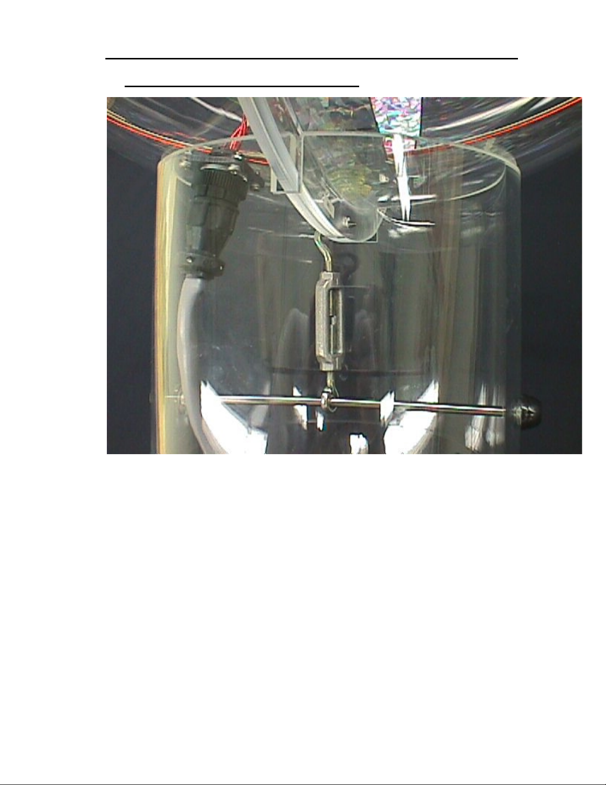
Figure 4-2 Long Ranger Transmitter Assembly and Cable Connection
When using the Lon g Ra nger Transmitter, attach t he t ur nbuckle the opening in the l ong r a ng er
and the bar inside the pedestal, as shown in Figure 4-2 above.
Step-By-Step System Installat io n 4-23
Page 27
Star★★★★Trak User Guide v001B
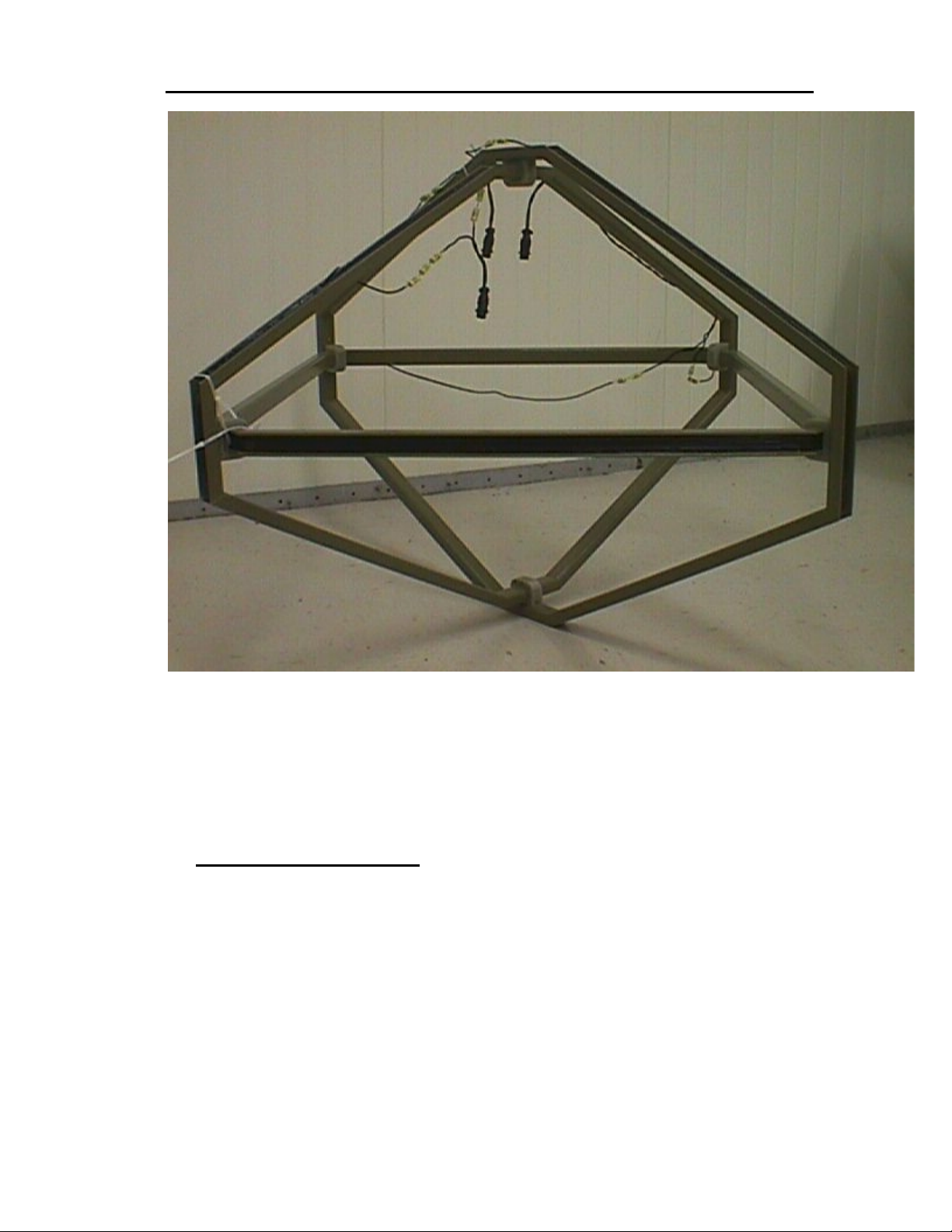
Figure 4-3 Super Nova Transmitter
If the optional Super Nova Transmitter is used in l ieu of the Long Ranger, attach its special
transmitter cable to th e three connectors of the Super N ova Transmitter, matching the X, Y,
and Z labeled connectors. See Figure 4-3 above.
Transmitter Mounting
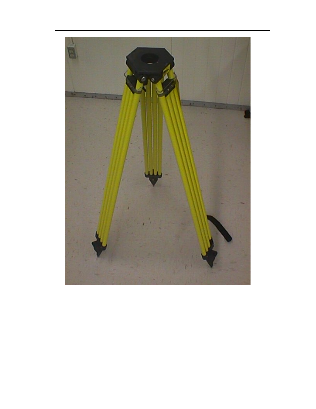
There are several t echniques for mounting th e Long Ranger T ransmitter. The method shown
uses the Polhemus custom non-metallic Tripod. (Refer to the following instructions for
mounting the transmitter to the custom Tripod m ount.) Mounting pr operly and secur ely is very
important since all measurements are made relative to its location.
1. Place the tripod in a low-traffic area to prevent accidentally disturbing the
transmitter. Avoid high-distortion areas such as those close to steel beams or
metallic siding.
2. Set up the tripod with the three legs positioned in a circle of at least 4 feet in
diameter for the lo west tripo d height. Extension of the tripod legs will requ ire t hat
Step-By-Step System Installation4-24
Page 28

Star★★★★Trak User Guide v001B
the legs be positioned in a c ircle of lar ger diam eter to m aintain s tabi lit y. Secur e a
restraining cord at the bottom of the legs to ensure stability of the assembly.
3. Place the transmitter mount on top of the tripod and fasten in place using the
three 1/2-2O UNC n ylon bolts and washers as s hown and tighten s ecurely. See
Figure 4-5.
3. 4. Raise the transmitter and route the cables through the 2-inch
diameter hole in the base of the mount. Be s ure that both the X and
Y coils are fully inserted into the notches provided.
4. 5. Install the mounting caps over the transmitter coils using the
fasteners provided and tighten securely.
Step-By-Step System Installat io n 4-25
Page 29
Star★★★★Trak User Guide v001B
Figure 4-4 Tripod
Step-By-Step System Installation4-26
Page 30
Star★★★★Trak User Guide v001B
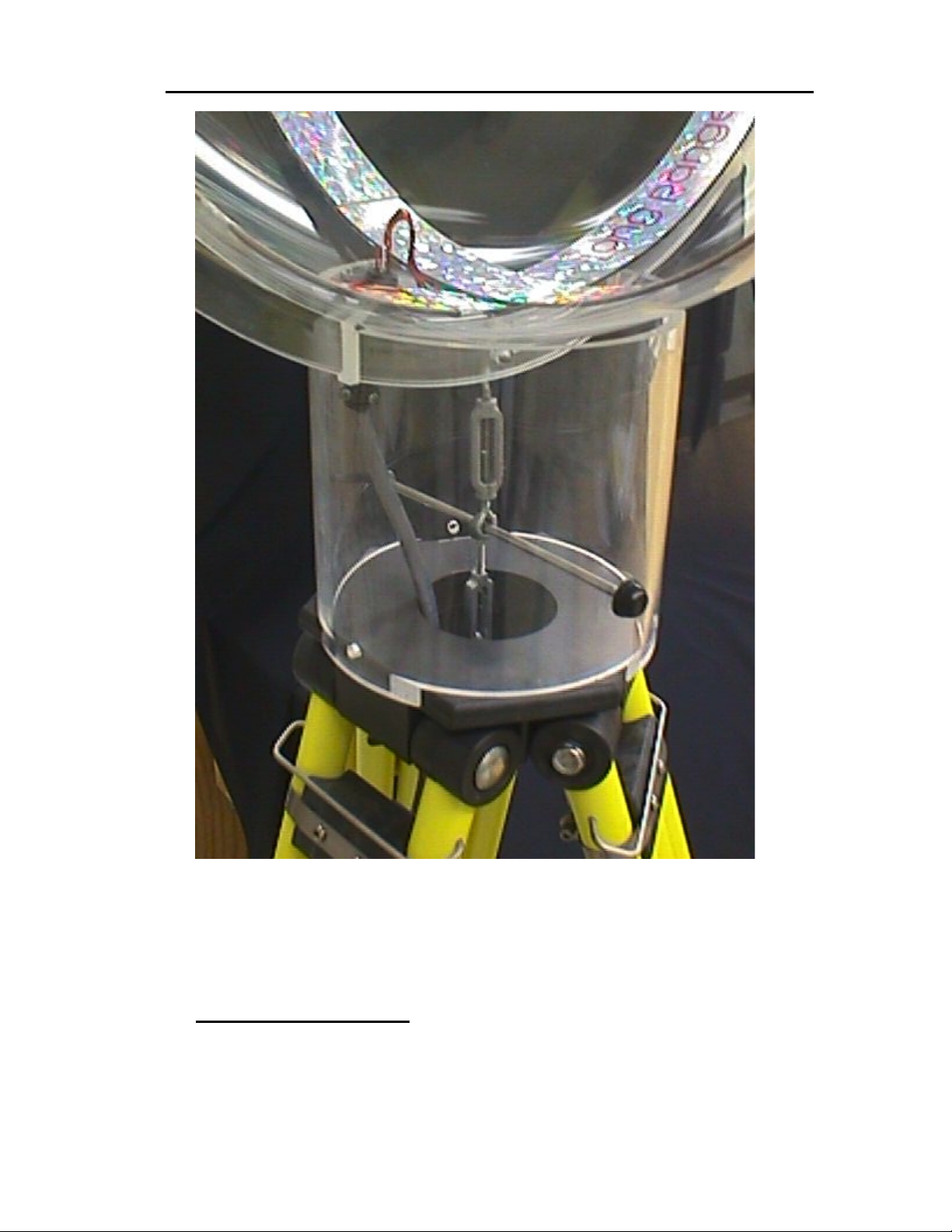
Figure 4-5 Long Ranger Transmitter Mounting Structure
Once the transmitter is mounted to the pedestal, attach the transmitter cable to the Long Ranger, and then set the
pedestal on top of the tripod base as shown in Figure 4-5 above.
System Interconnect
The overall system interconnect diagram (Figure 4-1) and the instructions that follow, will
describe how to set up the StarTrak system in the studio space.
Step-By-Step System Installat io n 4-27
Page 31

Star★★★★Trak User Guide v001B
Layout Considerations
The StarTrak system is designed to o perat e over a spac e as lar ge as 8 ft. x 16 f t. with a s ingle
Long Ranger transmitter. A m inimum range f rom the transm itter globe of approxim ately 1-foot
is also required; i.e. receivers sho uld always be at least 1 foot f rom the transmitter. A t ypical
installation may have the transmitter mounted on a tripod, centered in front or back of the
working area. A setup geometry such as this will allow a maximum range from the center of the
transmitter to the corner of an 8- f t x 16-f t perf ormance area to be 12 f t. It is also r ec om mended
that a non-metallic s ta ge b e b u ilt, t w o t o thre e feet high. This will al lo w the system to be f a rther
away from distorting materials contained in most floors.
The StarTrak system meas ures position and orientation base d on the relative pos itions of the
transmitter and receivers. Therefore, stable mounting of the transmitter is imperative. In
addition, the calibration process for the system requires that the transmitter be completely
stable during and af ter the calibration proces s. (If the transmitter is moved after a calibration
has been completed, then a new cal ibration is requir ed.) Proper preparation of the tr ansmitter
mount site must be considered and implemented prior to the start of a calibration.
Step-By-Step System Installation4-28
Page 32
StarTrak Component Interconnect
Star★★★★Trak User Guide v001B
Figure 4-6 Long Ranger Cable to Tuning Module
After securely mount ing the transmitter and att aching the cable, conn ect the other end of the
cable to the tuning module as shown in Figure 4-6 above.
Step-By-Step System Installat io n 4-29
Page 33
Star★★★★Trak User Guide v001B
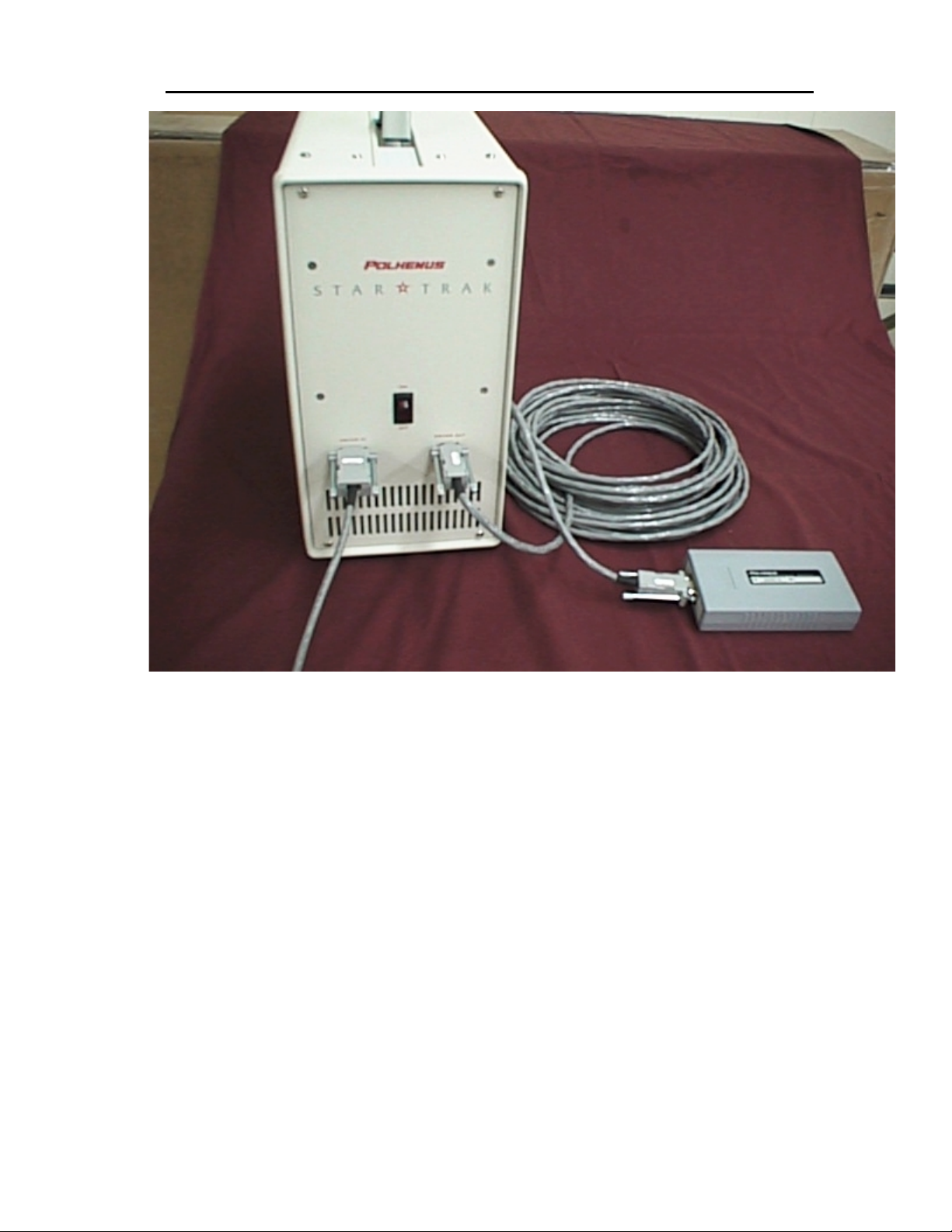
Figure 4-7 StarDrive Connections
Attach the transmitter cable from the tuning module to the right hand connector on the
StarDrive labeled “Dr iver out.” Then attach the St arDrive cable to the left-han d connector on
the StarDrive labeled “Driver in” as shown in Figure 4-7 above.
Step-By-Step System Installation4-30
Page 34
Star★★★★Trak User Guide v001B
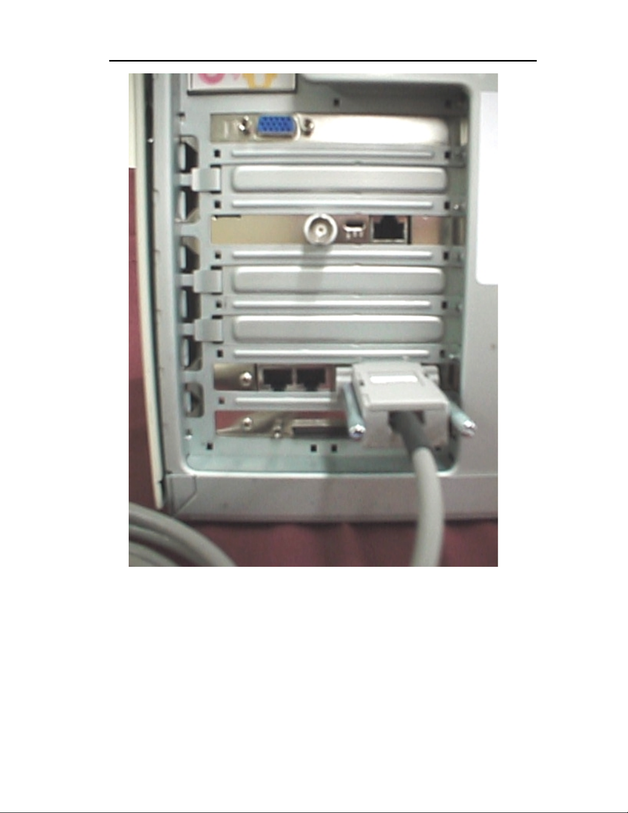
Figure 4-8 StarDrive to StarServe Connection
Connect the Server-Dri ver Cable from the “Drive In” conn ector on the StarDrive to th e DB15
connector on the back of the StarServe. See Figure 4-8 above.
Step-By-Step System Installat io n 4-31
Page 35
Star★★★★Trak User Guide v001B
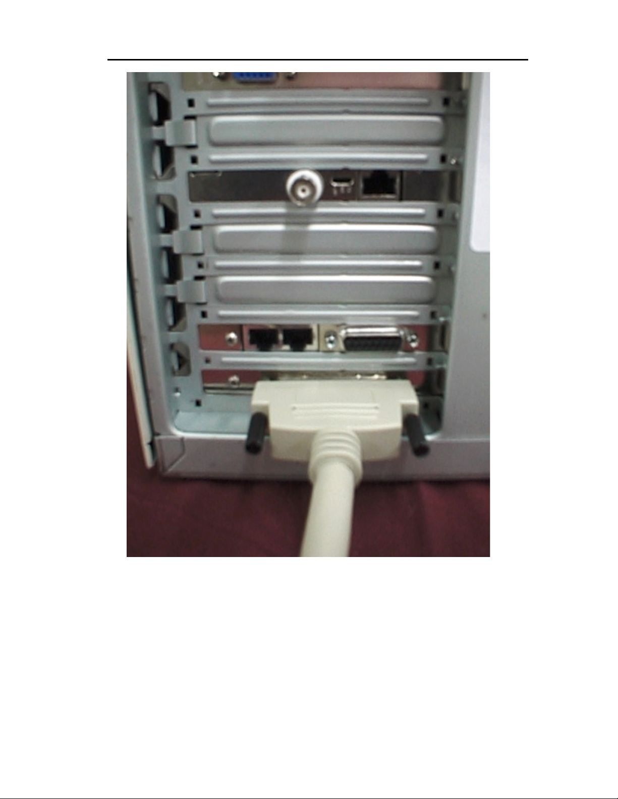
Figure 4-9 StarLink to StarServe Connection
If the RF transceiver card is installed in the StarPak, connect the StarLink via the SCSI,
Server-Link Cable t o the StarSer ve. See Figure 4-9 above. T his establis hes the RF li nk. If the
RF transceiver card is not installed do not connect the StarLink.
Step-By-Step System Installation4-32
Page 36
Star★★★★Trak User Guide v001B
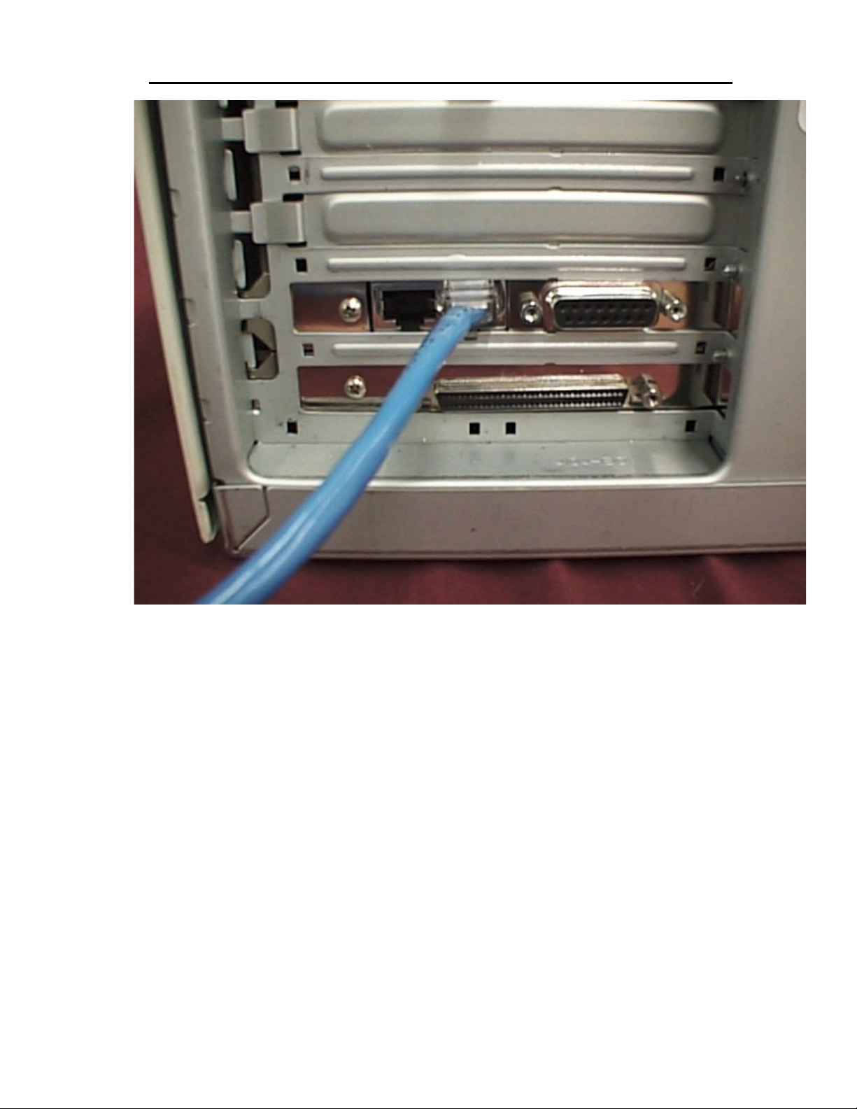
Figure 4-10 Tether to StarServe Connection
Connect one end of the tether to Port A at the back of the StarServe. See Figure 4-10 above.
Step-By-Step System Installat io n 4-33
Page 37
Star★★★★Trak User Guide v001B
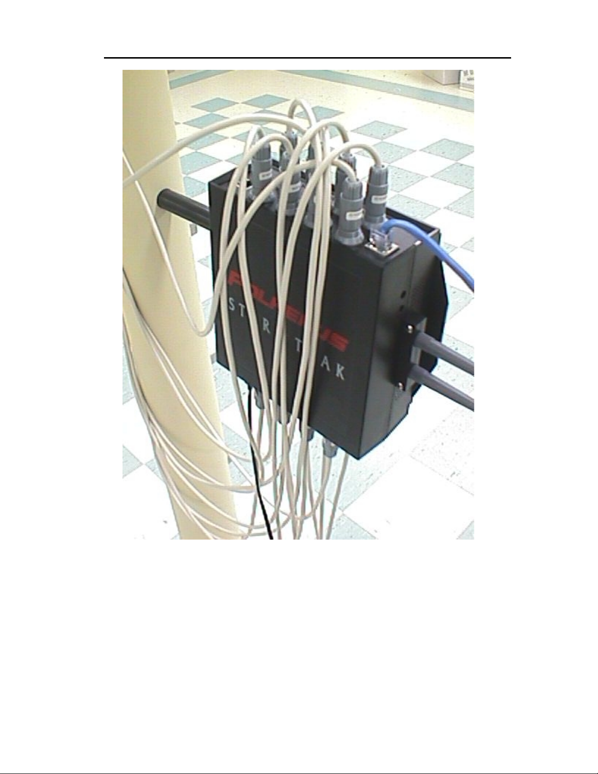
Figure 4-11 StarPack to Tether Cable Connection
Connect the other end of the tether cable and the receiver cab les to the Star Pak as shown in
Figure 4-11 above. You should hear a “cl ick” when each rece iver connector has been seated
properly.
Ensure that the Star Drive excitation cable is installed between the Star Drive Unit and the
StarServe. The power c ord to the Star Drive unit als o must be installed. Turn the Star Drive
power switch to the “ ON” position (lighted). Note: Since the StarDrive power is c onnected to
the StarServe, turning the StarServe power off automatically turns off the StarDrive power.
Step-By-Step System Installation4-34
Page 38
Star★★★★Trak User Guide v001B
Receivers
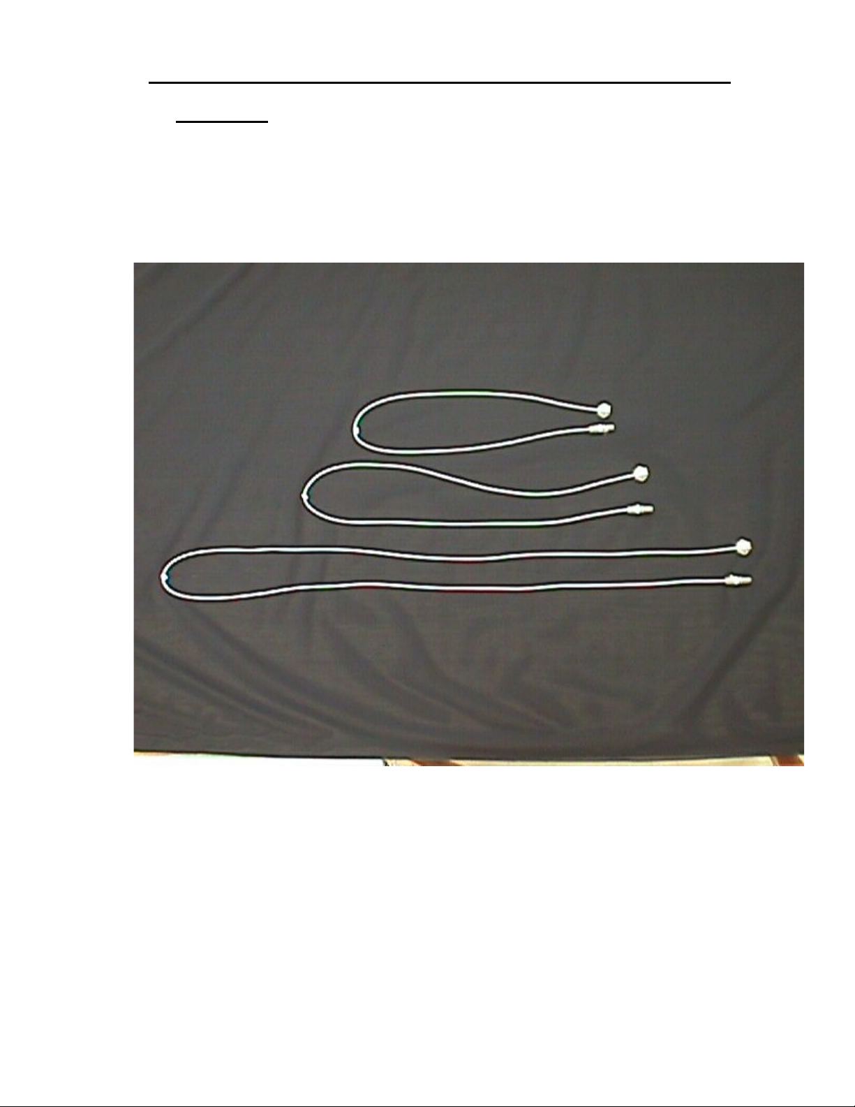
The small receivers are designed to provide a stable base to prevent unwanted rotational
movement when aff ixed to an actor. T hree cabl e lengths are provided and s hould be c arefull y
placed so that adequate movement without tugging on the receiver is achieved but without
leaving cable loops to catch onto objects.
It is also important to record which sensor port on the StarPak is used to connect to which
body part so that the host software can be initialized accordingly.
Figure 4-12 Receivers, various cable lengths
Step-By-Step System Installat io n 4-35
Page 39
Star★★★★Trak User Guide v001B
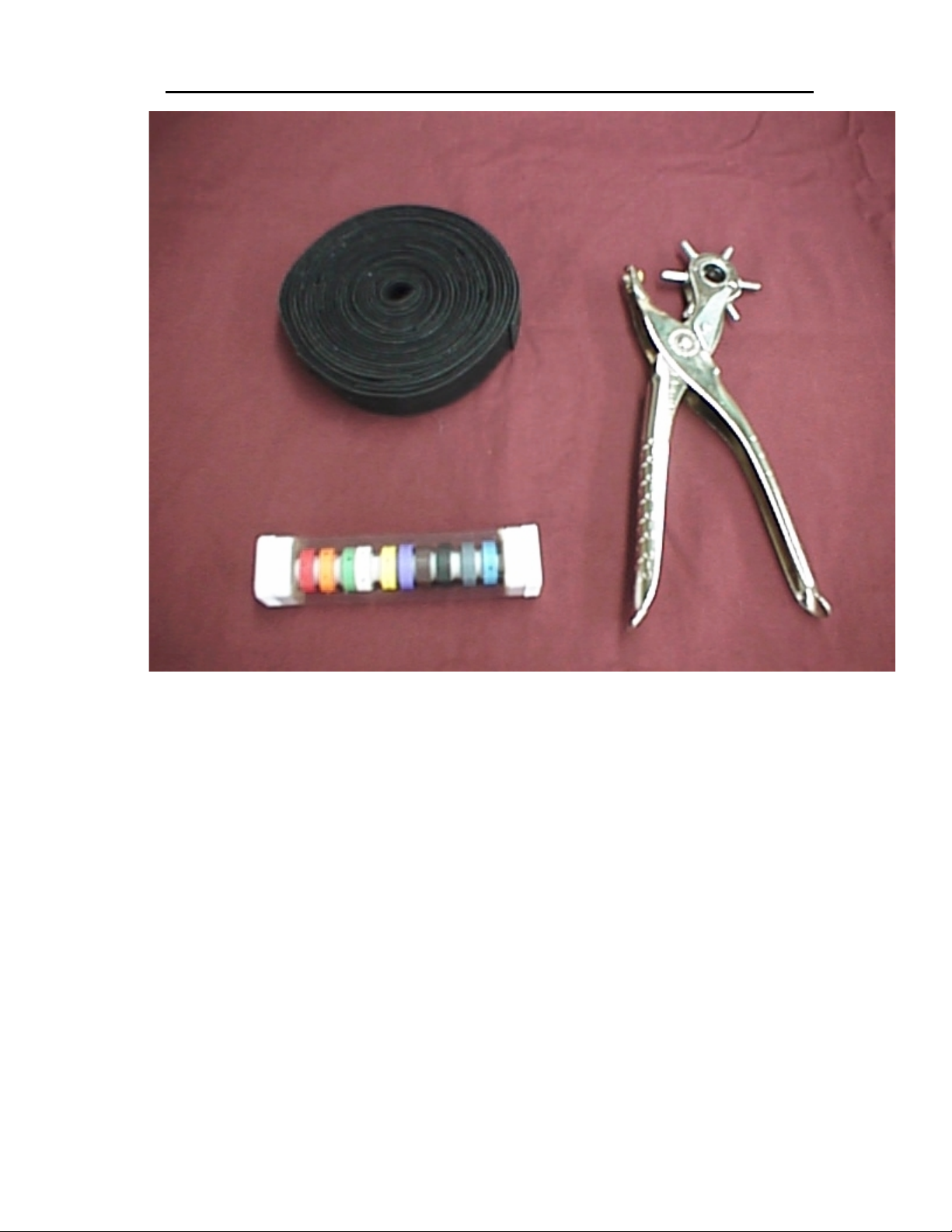
Figure 4-13 Receiver Mounting Kit
The receivers are mounted to the Per form er’s suit with the he lp of the “Rece iver Moun ting K it.”
This kit consists of multi-color ed cable marker s, a 10 meter r oll of double s ided Velcr o tape, a
hole punch, a punch template and push rivets. The Velcro is cut to correct lengths for attaching
the receivers to the perform er. Using the punch template as a guide, mounting holes are cut
into the Velcro with t he punch tool. Punch rivets (pus hed through the Velcro and r eceivers),
are used to retain the receivers to the Velcro. See Figure 4-13.
Step-By-Step System Installation4-36
Page 40
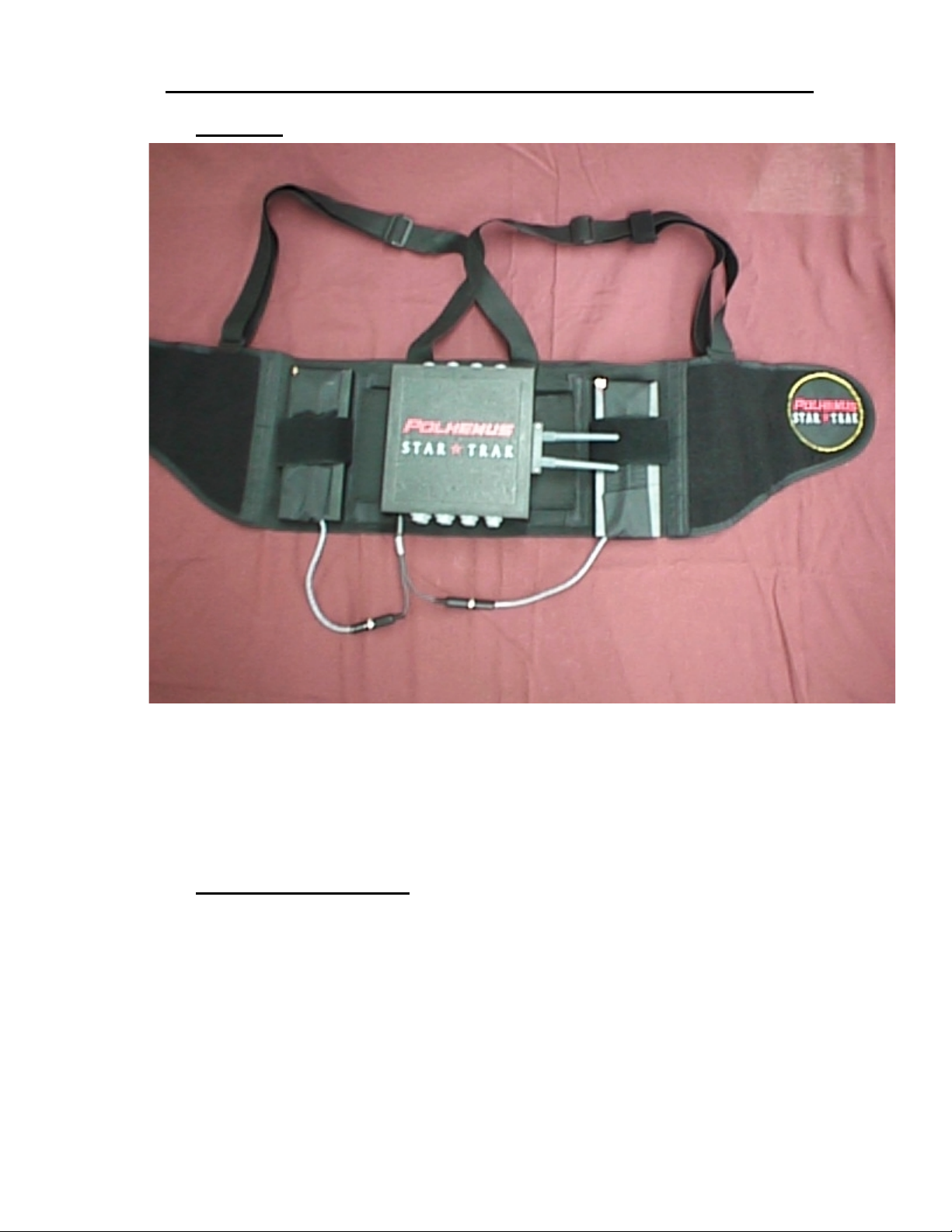
TrakBelt
Star★★★★Trak User Guide v001B
Figure 4-14 TrakBelt
Figure 4-14 illustrates the TrakBelt and the positioning of the StarPak and battery. For the
user’s convenience , the Belt is shippe d pre- as s embled. If the Belt is d isas s embled please not e
the positioning and routing of the cables to aid in re-assembly.
Ethernet Connection
The StarTrak StarSer ve pr ovides out put via E thern et cab les (1 0Base T or 10Bas e 2). C onnect
to the appropriate connector on the Ethernet board at the rear of the server. All Ethernet
drivers are pre-ins talled. Polhemus has provid ed a special 10 Base T Crossov er Ethernet
cable. This cable will allow direct connection with a host machine without the use of an
Ethernet Hub. If a standard 10 Base T cable is used, then a Hub must be utilized.
Step-By-Step System Installat io n 4-37
Page 41
Star★★★★Trak User Guide v001B
4.2 S
TARTING UP STARTRAK
Start the Server
After the system is fully connected as described above, turn on the system power at the
StarServe (front panel power s witch). The system will go through CPU diagnostics and boot
into the Windows NT workstation desktop.
Launch the StarTrak monitor application by double clicking the StarTrak icon on the desktop.
Launch the StarTrak Application
Launch the StarTrak application by double clicking the StarTrak icon on the
desktop. The StarTrak main window will appear with the Status windo w active. If there are any
problems with this launch (driver startup, etc), error messages will be displayed in the status
bar at the bottom of the window and recorded in the error log.
Start the MAC
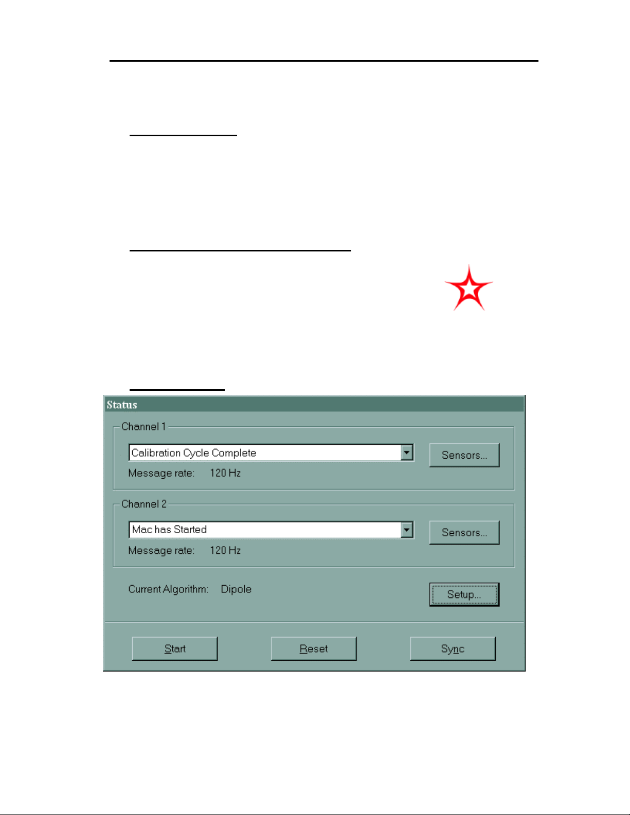
Figure 4-15 StarServe Main Window
Start the StarTrak Media Acces s Controller (MAC) . Se lect th e “ST ART” button on the ST AT US
window of the StarTrak monitor. Several “loa d” message windo ws will appear followe d by the
Step-By-Step System Installation4-38
Page 42
Star★★★★Trak User Guide v001B
message “MAC Star ted” displayed in the status mes sage dropdown box (of both chan nels).
Again, if there are problems with this part of the startup procedure, error messages will be
displayed and logged.
Power up StarPack
Prepare to receive Star Pak data. C onnect the Star Pak batter y, located on the T rakBelt, to the
StarPak. A series of messages should be displayed in the status m essage dropdown box (s).
When the “Mac Characterization Xfer Done” message is displayed, select the “SYNC”
button. Upon reception of the “Calibration Complete” message, field data, P&O data,
characterization data, and calibration data may be reviewed.
Verify Active Sensors
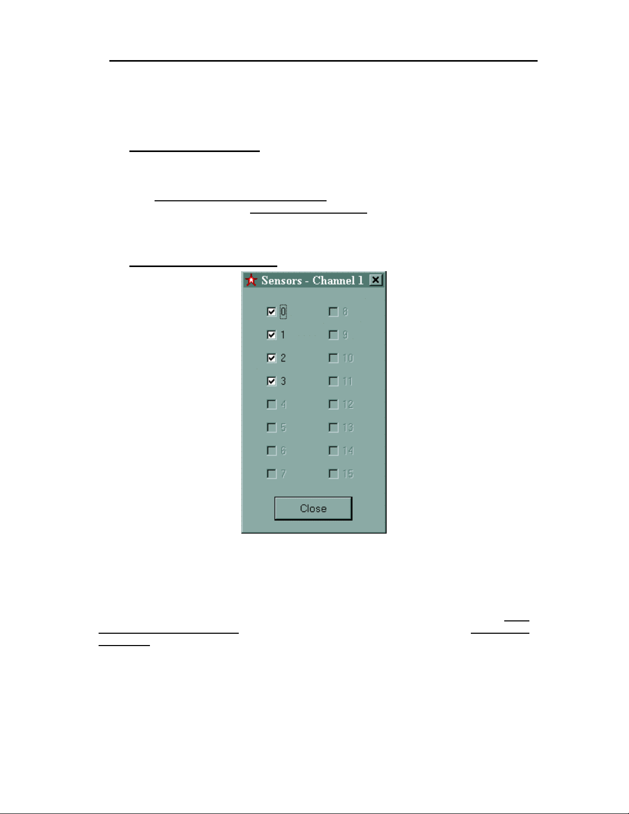
Figure 4-16 Channel Sensors View
Verify the number of active sensors in the “Channel Sensors View.” Upon selecting the
appropriate “Sensors” button, review the active s ensor list. A check ed box denotes an active
sensor (receiver). If the number and position of the conn ected receivers do not match the l ist,
verify all connections and then select the “RESET” button. Upon reception of the “Mac
Characterization Xfer Done” message, select the “SYNC” button. When the “Calibration
Complete” message is displayed check the active sensor list again.
Step-By-Step System Installat io n 4-39
Page 43
Star★★★★Trak User Guide v001B
Examine Sensor Characterization and Calibration Data
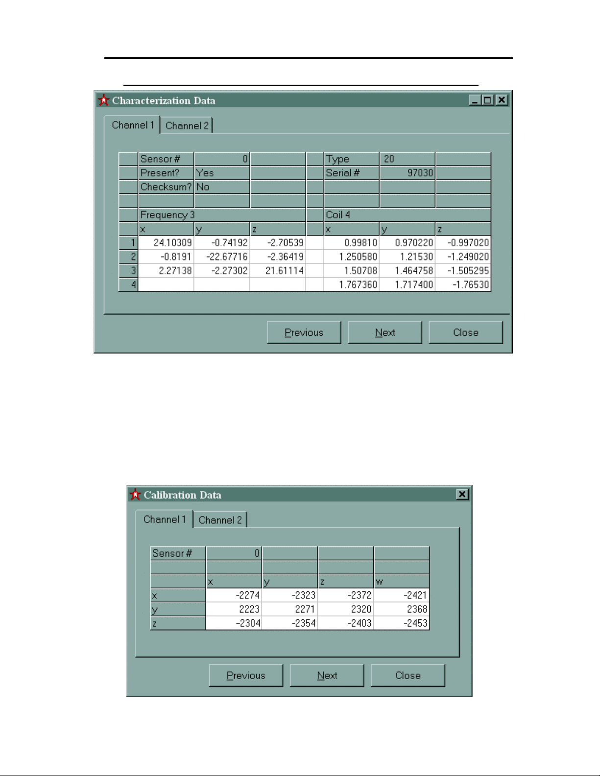
Figure 4-17 Sensor Characterization Data Display
As a quick check of sensor integrity, examine both t he characterization and calibratio n data
sent by the StarPak to the StarServe. To check the characterization data, select
“Characterization Data” from the Diagnostics list in the main menu or select the
characterization icon on the toolbar. Scrolling thr ough each sens or (next/prev ious buttons ) the
diagonal elements (x,1 : y,2 : z,3) of the “fr equenc y 3” m atr ix should ha ve va lues between +20
and +25 or between –25 and –20. The magnitude of the remaining elements should be no
greater than 2. If no sensors are connected, the data will be meaningless.
Step-By-Step System Installation4-40
Page 44
Star★★★★Trak User Guide v001B
Figure 4- 18 Receiver Calibration Data Display
Calibration data may be viewed by select ing “Calibration Data” from the Diagnost ics list in the
main menu or b y selecting the cal ibration icon o n the toolbar. Each receiver’s calibration d ata
may be examined by using the “next” or “previous” buttons. All magnitudes within the
calibration matrix should lie between 1900 and 2300 (signs may vary).
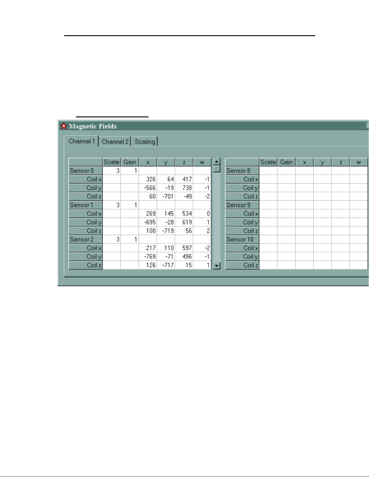
Display Field Data
Figure 4-19 Field Data Display
With all expected sensors listed, display the f ield data window. T his window m ay be activated
by selecting from the main menu or by clicking on the toolbar icon. Scroll the screen to
examine that field dat a is pr esente d for each se nsor connec ted. T here sh ould b e four c olum ns
of data representing data from each winding of the transmitters - X, Y, Z and W. With one
transmitter present only the first three columns will contain data and the fourth column will
display small number s close to zero. The fie ld data should be r easonably sta ble in magnitud e
and sign when the sensors are stationary and within 12 feet of the transmitter.
Step-By-Step System Installat io n 4-41
Page 45
Star★★★★Trak User Guide v001B
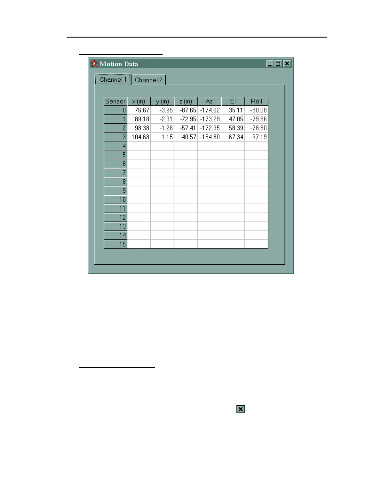
Display Motion Data
Figure 4-20 Motion Data Display
The Motion Data windo w may be displ ayed by selecti ng it from the dr opdown list on t he main
menu bar or by selecting the Motion Data icon on the t oolbar . Each s ens or will displ a y position
and orientation (P&O) values in seve n colum ns ( receiver num ber, X, Y, Z transl ation, a zimuth,
elevation, and roll). At t his point, however, these numbers will have limited meaning becaus e
the motion capture spac e has not been calibr ated. For diagnostic observations se lect Display
Field data from the menu.
Stopping StarTrak
Stopping the StarTrak system requires both shutting down the StarTrak application and
severing the RF link between the StarServe and the StarPak(s).
To terminate the StarTrak applic ation on the Star Serv e, selec t “Exi t” f rom the file m enu or c lic k
on the “close window” icon (in the main window), or click on the
Removing power from the StarPak(s) terminates the RF link between the pack(s) and server.
.
Step-By-Step System Installation4-42
Page 46

Star★★★★Trak User Guide v001B
4.3 E
NVIRONMENT MODEL
Before you Begin Using Data
The procedure to be performed here is most critical for StarTrak system installation. This
chapter describes how to build the environment model through a process referred to as an
Environment Calibration. The environment model is used to equalize unusual amounts of
metal that affect m agnetic-based motion track ing systems. Therefor e, this process should be
performed caref ully to spec ificatio n. Befor e proceedi ng, ver ify from the list be low that al l of the
required equipment is present. If you have difficulty in understanding this chapter, our
Polhemus technical support engineers are on-line ready to answer your questions.
Required Equipment
1. StarServe 4A0436-01
• Cable, Tether A3L79b10BL-MW
• Power Cord 17500-BLK
2. StarDrive 4A0426-01
• Power Cord 17500-BLK
• Cable, Server – Driver 2A0596-01
3. StarLink 4A0438-01 (Channel 1)
• Cable, SCSI, Server-Link
DCA2775/MD68MM10
4. Long Ranger 4A0345-02
• Cable, Driver- Tuning Module 3A0542-03
• Tuning Cap Module, X, Y, Z 3A0583-01
• Cable, Tuning Module – Long Ranger 3A0581-01
• Tripod with Pedestal (optional) 2A0366-01
5. Calibration Fixture 4A0443-01
• StarPak, RF 16 Receivers 4A0435-01-A (Channel
1)
Step-By-Step System Installat io n 4-43
Page 47

Star★★★★Trak User Guide v001B
• Battery Assembly (2) 2A0497-02
• Cable, StarPak-Battery Y 2A0622-01
• StarPak-Battery 2A0624-01
• Receivers
1. 36” Receiver Assembly (4) 4A0434-01
2. 48” Receiver Assembly (5) 4A0434-02
3. 66” Receiver Assembly (7) 4A0434-03
Setting Up
Introduction
This section desc ribes the hard ware co nnect ions re quire d to po wer u p th e S tarT rak
system. Refer to the P C’s User Manual for instruc tions on connectin g the PC and
accessories. Windows NT and the StarTrak software are installed at the factory.
Hardware Configuration
• Calibration dat a can be co llec ted wire less over th e RF link or through t he t ether
cable. If the prism PCMCIA c ard is not i nstal led, d ata co llectio n is don e thr ough
the tether which remains connected throughout the calibration process.
Channel 1 or 2 wireless may be used for calibration. A fa ctory set switc h on the StarP ak presets t he
•
pack for either Channel 1 or 2 and is identified by the part number. For this discussion, Channel 1 will
be used. (Replacing 1 with 2 throughout this procedure will describe calibration using Channel 2
StarPak).
NOTE: The StarLink (4A0438-01) has Channel 1 only. StarLink (4A0438-02) is
required to establish an RF link over Channel 2.
• Apply AC power to the StarDr ive.
• Connect the Tether Cable to the StarPak.
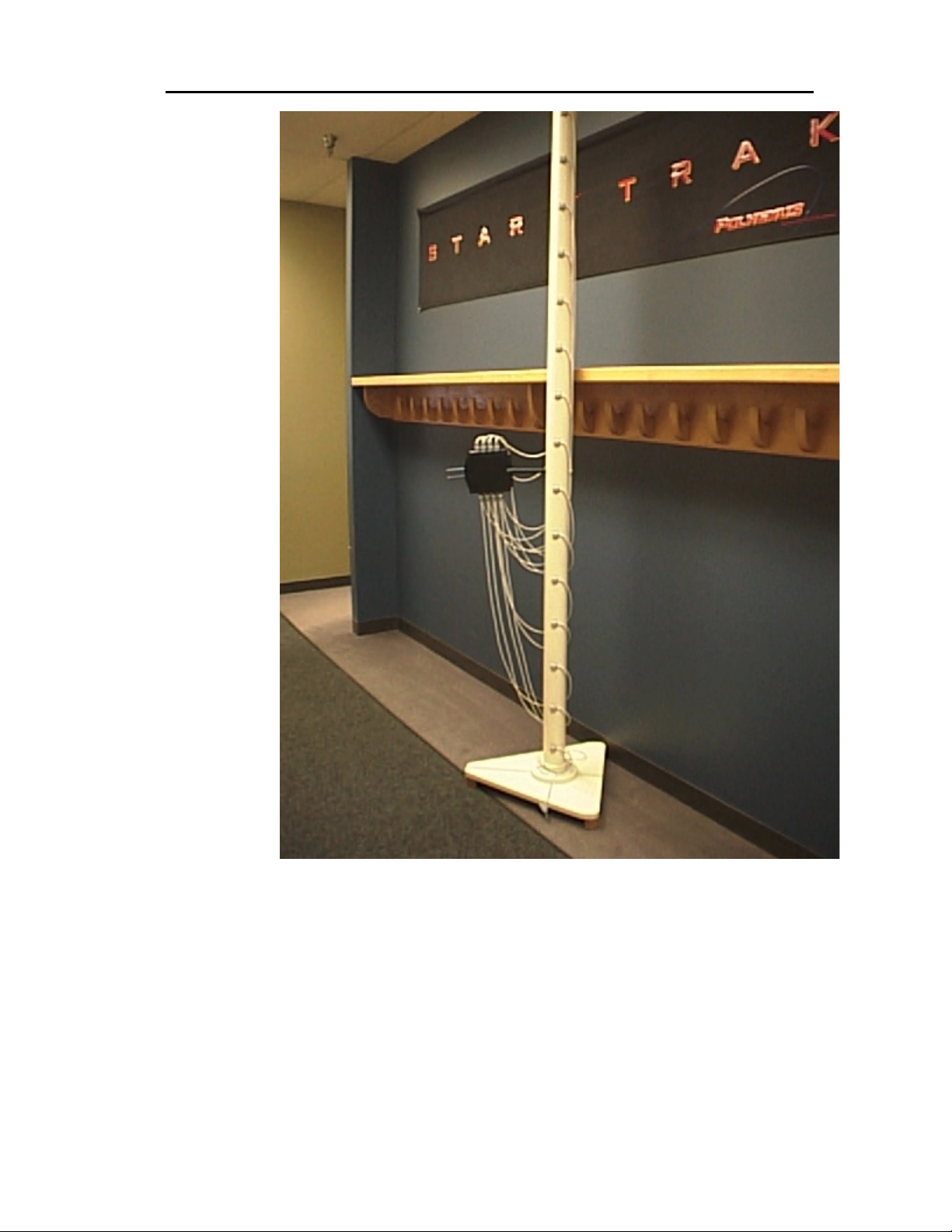
• Assemble the Calibration Fixture as shown in Figure 4-21. Note: There are 3
different receiver cable lengths. Care should be taken when mounting the
receivers to the fixture to ensure that each receiver’s cable will reach the
StarPak’s location.
Step-By-Step System Installation4-44
Page 48
Star★★★★Trak User Guide v001B
Figure 4- 21 Calibration Fixture
• Make certain the receiver’s position on the calibration fixture matches the
number on the StarPak when connecting.
Note: When perform ing an 8-receiver ca libration rather t han a 16, aff ix receivers to the
pole in “every other” position, starting at the bottom.
• Sec urely fasten the batter ies to the base of the calibration f ixture. Connect the
batteries to the StarPak using the StarPak -Battery “Y” cable and the extender
cable.
Step-By-Step System Installat io n 4-45
Page 49

Star★★★★Trak User Guide v001B
CAUTION: SECURE THE ST ARPAK BATTERY C ABLE AWAY FROM THE RECEIVERS’
SHELLS & CABLES. CLOSE PROXIM ITY BETWEEN THIS C ABLE AND THE RECEI VERS
WILL RESULT IN ERRONEOUS DATA.
Software Configuration and Operational Setup
• Power on the StarServe following the steps described in the PC User Manual.
• Double-click on “STARTRAK.EXE” icon.
CAUTION: PRIOR TO INITIATING THE CALIBRATION CYCLE, MOVE THE FIXTURE AT
LEAST THREE FEET FROM THE TRANSMITTER TO ENSURE PROPER RECEIVER
CALIBRATION.
• From the Status Window, click on the “Start” button.
1. “Mac Has Started” message will be displayed in the Channel 1 Display
window.
2. Wait for “Mac Characterization Xfr Done” m essage. Occasion ally, messages
can be missed over the RF link and therefor, will not be received by the
operator. After 10 sec onds wi th no in dic at io n of Mac characterization trans f er
done, single-click on the “Reset” button and wait for the message. If the
server fails to rec eive the mes sage again, look for an illum inated yellow LED
on the StarPak indicating a successful RF link. “Reset” the system. If the
yellow LED is still not lit or flashing, power down the StarPak and reapply
power. Return to Step X.X. If problem persists contact Cus tomer Service at
Polhemus (800) 357-4777 (USA and Canada, only) or (802) 655-3159.
• Single-click on the “Sync” Button.
1. “Calibration Cycle Started” message will be displayed in the Channel 1
Display window.
2. Wait for “Calibration Cycle Complete” message.
• Single-click on “Calibration Data” icon of toolbar.
1. Check for approximately –1900 ➙ -2800 range.
2. Click on “Next” to view each rec eiver’s c alibration data. Eac h one should f all
within this range.
3. If the data is outside the specified ra nge, verif y that the f ixture is far enough
away from the transm itter and “Reset” the system. If the problem persists,
call Customer Service.
• Single-click on “Characterization Data.”
1. The data on the left is the characterization m atrix for the rec eiver. The data
on the right is the calibration data.
2. Click on “Next” to view each receiver’s characterization data
Step-By-Step System Installation4-46
Page 50

Star★★★★Trak User Guide v001B
3. In order to avoid co nnecting the receivers to the StarPak out of sequence,
verify that the last t hree digits of the displayed seri al number matches with
the receiver’s serial number mounted in that position on the calibration
fixture.
• If the server didn’t recei ve char acter i zat io n d ata, check the receiver c onn ecti ons
and “Reset” the system. If the problem persists, call Customer Service.
• Single-click on the “Setup” button and select the “Dipole” folder. Set the
hemisphere vector to the +X hemisphere.
1. Enter 1 for the X component and 0 for the Y and Z components.
• A helpf ul aid in finding a goo d transmitter locatio n is the “Motion View” screen.
Select the “Motion V iew” icon. This windo w shows a graphic represe ntation of
the 16 sensor posit ions. (The transm itter position where the graphic of the line
of receivers stays the straightest will be the best position. The next section goes
into greater detail about finding a suitable Transmitter mounting position.)
Transmitter Location, Orientation and Hemisphere
• Choose a transmitter location that is away from large distorting objects and
somewhat close to the motion capture s pace. Secur ely m ount the Long R anger
transmitter in an optimum location by using the following steps.
• Position the trans mitter or ientatio n so that t he +Z ax is is point ing do wn to wards
the ground. Typically, the +X hemisphere is used in the calibration process.
Therefore, the +X ax is shou ld point t oward the m otion captur e space. Optim um
range between the transmitter and any collection point is 2 to12 feet.
• Place the c al ibrat ion fixture in sever al loc a tio ns an d o bs erve the pos i tio ns f or all
the fixture’s receivers by using t he “Moti on Vie w” and “Motio n Data” wind ows in
the software. (Ref er to the Software S ection for details). Be ware of an unusual
amount of error bet ween the 16 rece ivers. W ith experience, you will be able to
judge whether or not a region can be s uccessfully calibr ated. If the error is too
large (+ or – 30 degrees of deviation, + or – 25 inches deflection), then
reposition the transmitter and repeat the test.
• After determining a transmitter position that will produce a successful
calibration, securely mount the transmitter to its final location.
• If there are future plans to move the Long Ranger transmitter, it must be
mounted in a manner such that it can be precisely repositioned to the exact
same physical position and orientation in order to preserve the environment
calibration.
Define the Mapping Grid
The grid pattern is defined in two places: (1) in the StarTrak software, and (2) on the
studio floor or stage. A twelve-inch grid pattern has been adopted to collect
Step-By-Step System Installat io n 4-47
Page 51

Star★★★★Trak User Guide v001B
calibration data. T his is not a sta ndard. If a sm aller or m etric grid is re quired, then it
should be used. The maximum number of grid points in any direction is 180.
• Create the desired gri d pattern usin g a carpent er’s chalk line on the sta ge floor
or on construction paper securely attached to the stage floor.
• The precise loca tion of the transmitter relative to the motion captur e space is
required by the StarTrak system when defining a grid.
• Drop a plum b bob from the center of the Long Ranger tr ansmitter to the floor.
Place a piece of tape on the floor below the plum b bob and mark the center.
Measure the X and Y center of the Long Ranger transmitter to the first grid
point in the collection process. The first grid point is the minimum X and
minimum Y distances from the transmitter. These two m easurem ents are the X
offset and Y offs et parameters defined in t he StarTrak Calibration and Mapping
option.
NOTE: For most applications, minimum Y is normally a negative value and is
entered as such in the software
• Measure the Z offset from the stage floor to the center of the Long Ranger
transmitter. This will be defined as the Z of fset in the Calibrat ion and Mappin g
option.
.
Data Collection
Map Setup
• Select the “Calibration and Mapping” choice from the Tools Menu on the
StarTrak program’s main window. This will display the “Map Setup” window.
• Map Area
This section def ines the total area of the desired calibrated space (length (X) and width ( Y))
and units.
1. Select Map Units, either English Standard or Metric.
2. Enter the “X distance” in feet, inches, centimeters or meters.
3. Enter the “Y distance” in feet, inches, centimeters or meters.
4. Enter the “Grid Size” i n f eet, inches , c e ntimeters or m eters . Note: The default
grid size is 12 inches
Step-By-Step System Installation4-48
Page 52

Star★★★★Trak User Guide v001B
• Pole Setup
This section defines the StarPak channel, number of receivers and number of samples
averaged for each point.
1. Enter “Using channel:” as 1.
2. Enter “R eceivers to Map:” as 16 or 8, depending on the number of sensors
you are using on your mapping pole.
3. Enter “Points to Average.” The default value for this is 100 samples. The
software retains n ew settings.
Note: See “Pole Setup” for more information about these fields.
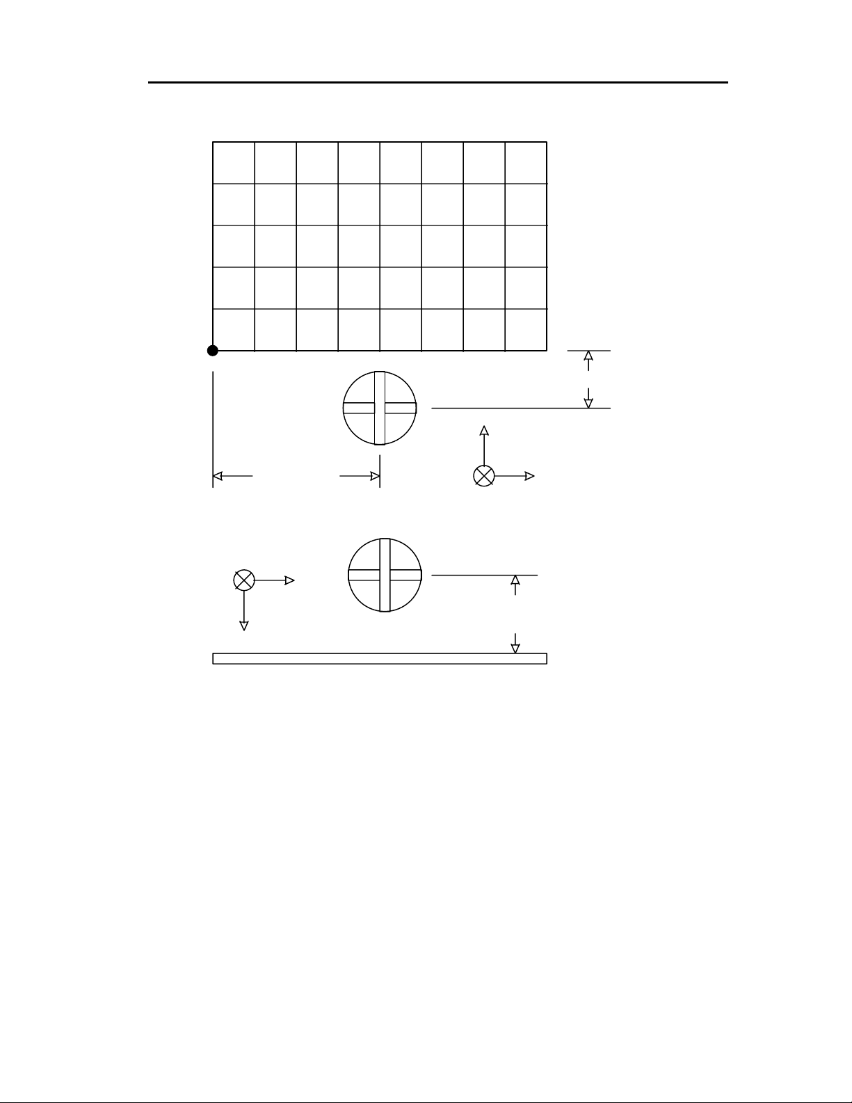
• Relative Position
This is the measured offset distance between the center of the transmitter and the first
calibration point. See Figure 4-22. All measurements are made from the center of the
transmitter, which is the 0,0,0 origin location.
1. Enter “X offset:”
2. Enter “Y offset:”
3. Enter “Z offset:”
Mapping Process
• Click on the “Start” button. This will start the collection process.
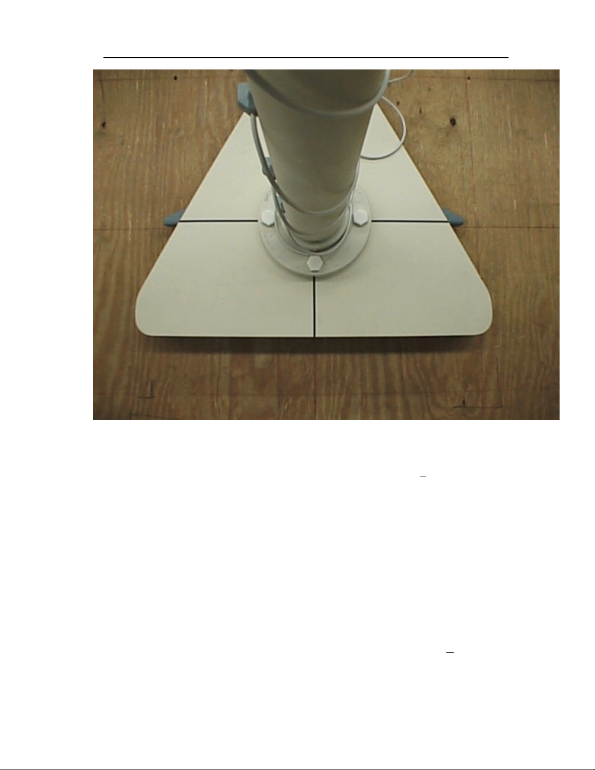
• The Map Collecti on Screen will sh ow the “(0, 0)” start po int. Plac e the calibr ation
fixture at the “0.0” star t point. For pr oper alignm ent of calibra tion fixture and grid
refer to Figure 4-7. To collec t a dat a p oi nt, pr ess <ent er > or c lic k the “OK” button.
The bar at the top of the screen will scroll across while the data is being
averaged and written to a file. Repeat this procedure until all of the grid points
have been collected . In the event of an error during col lection, a “Back” button
deletes the previously taken data point and allows the user to retake the point.
Step-By-Step System Installat io n 4-49
Page 53
Star★★★★Trak User Guide v001B
First Grid
Point
TOP VIEW
Minimum X
+X
Minimum Y
SIDE VIEW
+Y
+Z
Figure 4-22, Calibration Region and Transmitter Offsets
+Y
Minimum Z
Step-By-Step System Installation4-50
Page 54
Star★★★★Trak User Guide v001B
Figure 4-23 Calibration Fixture on Grid
• Upon complet ion of the data collection process, selec t the “Save” button. In the
window “Save Map As…” give the data a f ilename. T his file will autom atically be
given the extension “. LUB.” The collected data is saved in the directory
C:\Program Files\Polhemus. (This is the compensation file.)
Apply Area Compensation File
• Click on the “Mot ion View” ic on from the tool bar. This wi ll allow you to vi ew the
Calibration Pole receivers on a graphic representation display.
• Click on the “ Setup” button. Selecting a n “Area Model (LUB)” f rom the “Dipole”
folder turns compensation on. Clic k the “Area Mode l (LUB)” button. The “ Select
Area Map” window will appear. Select the .lub file just created and Open it.
• From the “Dipole” window select the “Apply” button. The Motion View window
will update the display from uncompensated to compensated receivers. Close
the “Options” window.
Step-By-Step System Installat io n 4-51
Page 55

Star★★★★Trak User Guide v001B
• View “Motio n Data” for absolute and r elative acc urac y. The lin e of recei vers now
should appear straight as the pole is moved through the calibrated environment.
Step-By-Step System Installation4-52
Page 56

5 System Operation
Star★★★★Trak User Guide v001B
5.1 I
Using the StarTrak motion capture system requires two human elements: (1) the 'performer(s)'
and (2) the 'operator' controlling the system.
NTRODUCTION
StarTrak Performer
When immersed in a stable m agnetic f ield, the St arT rak perf ormer produces the m otion that is
sensed by up to 16 rec eivers af fixed to the p erform er’s bodysu it. The perf ormer’s StarPak unit
collects raw data r epresenting positio n and orientation. The collected data are packaged a nd
transmitted via wireless/single tether to the StarServe under Operator control. Up to two
performers are supported in this configuration.
StarTrak Opera tor
The StarTrak operator controls and monitors the motion capture process. The primary tool
used by the operator is the StarTrak application running under Windows NT.
5.2 S
TARTRAK MAIN WINDOW
Introduction
For the most part, the S tarTrak user interface is consiste nt with the standard windows “look
and feel.” The StarTrak application uses a single primary window called the
Window
provides control of the StarTrak system.
to visually contain a series of child windows. Each child window displays data or
System Operation 5-53
StarTrak Main
Page 57
Star★★★★Trak User Guide v001B
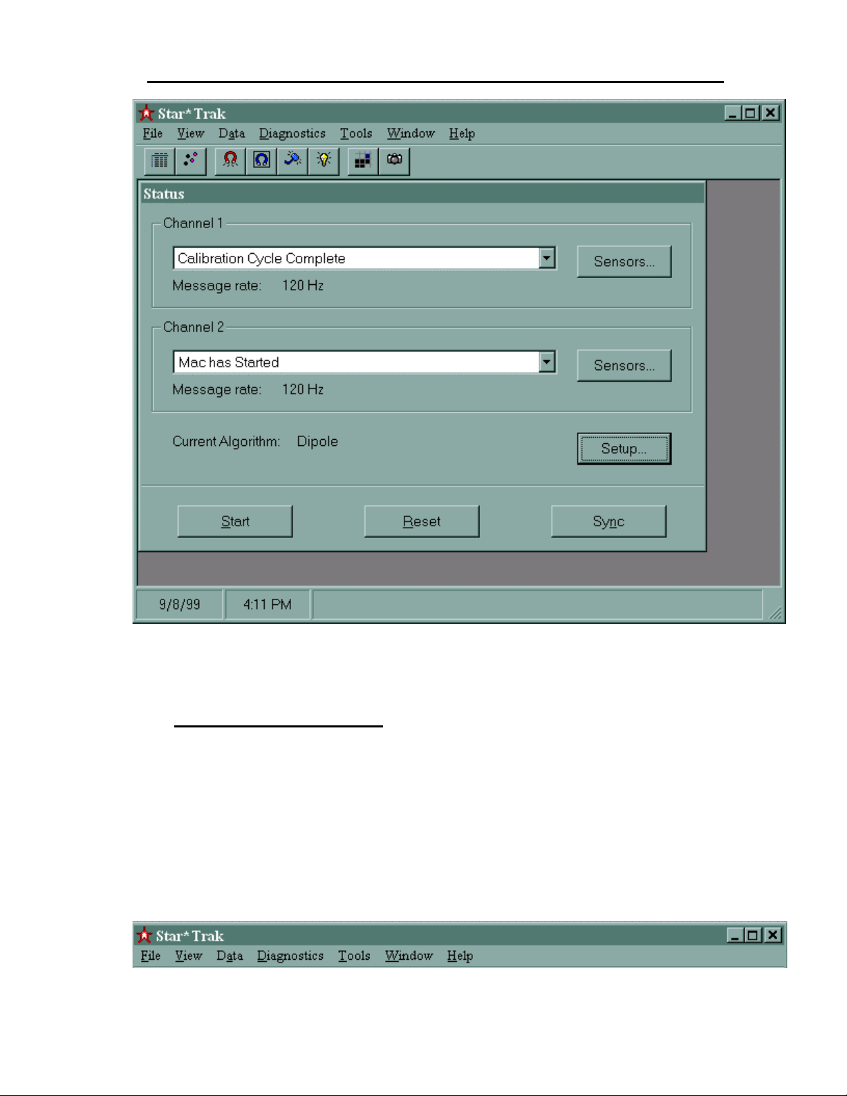
Figure 5-1, StarTrak Main Window
Main Window Controls
For the beginning windows user, a few of the standard main window controls em ployed by
StarTrak are the Menu Bar, the Tool Bar, and the Status Bar.
Menu Bar
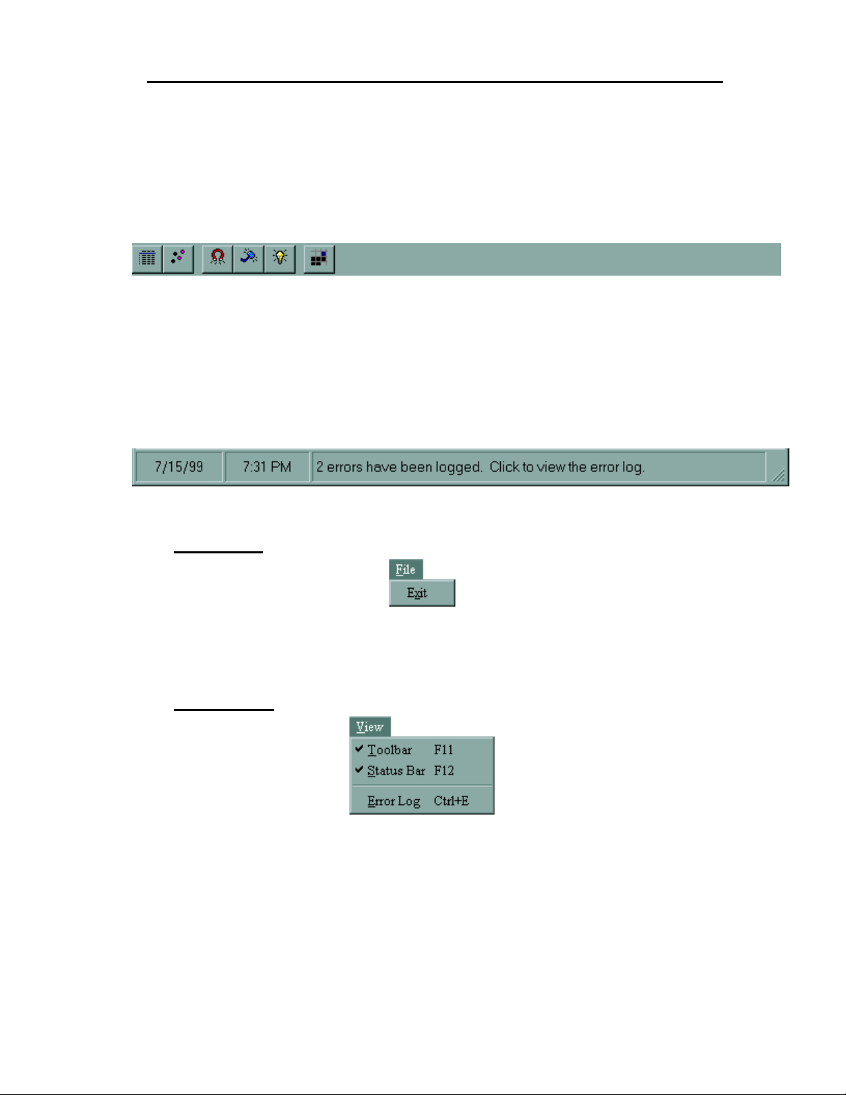
The menu bar located at the top of the main window inc ludes a series of menu “ titles” which
provide access to drop-down menus. The drop-down menus provided by the StarTrak main
window are File, Vi ew, Data, Diagnostics, Tools, an d Help. Click on each t itle in the graphic
below for an explanation of the menu choices available there.
System Operation5-54
Page 58
Star★★★★Trak User Guide v001B
Tool Bar
The Tool Bar is a series of icon buttons that allow rapid launching of com monly used views.
These views include: New Motion Capture, Open Motion Capture, Save Motion Capture,
Motion Data, Motion View, Magnetic Field Data, Charac terization Data, Cali bration Data and
Mapping. These vie ws also c an b e launc hed f rom a m enu item (see above) a nd are des crib ed
in detail later i n this document. The toolbar is an optional feature; it m ay be disabled b y deselecting “Toolbar” in the View menu.
Status Bar
The Status Bar, located at the bottom of the main window, displays time, date and system
status messages. Er ror m es sages dis pla yed her e are r ec orde d i n a n err or log. If the stat us bar
displays the presence of an error message, simply click on the status bar for a shortcut to open
the Error Log view. The Error Log view a lso is ac cess ible v ia the Vie w m enu. T he status bar is
an optional feature; it may be disabled by de-selecting “Status Bar” in the View menu.
File Menu
The file menu contai ns only one choice, for ex iting the application. T o quit StarTrak, click on
the Exit choice.
View Menu
The View menu contains choices for changing the appearanc e of the main window. Yo u can
enable/disable the Toolbar and the Status Bar by clicking on the appropriate choices.
The Error Log choice launches the Error Log view. See Error Logging for more information
about this choice.
System Operation 5-55
Page 59
Star★★★★Trak User Guide v001B
Error Logging
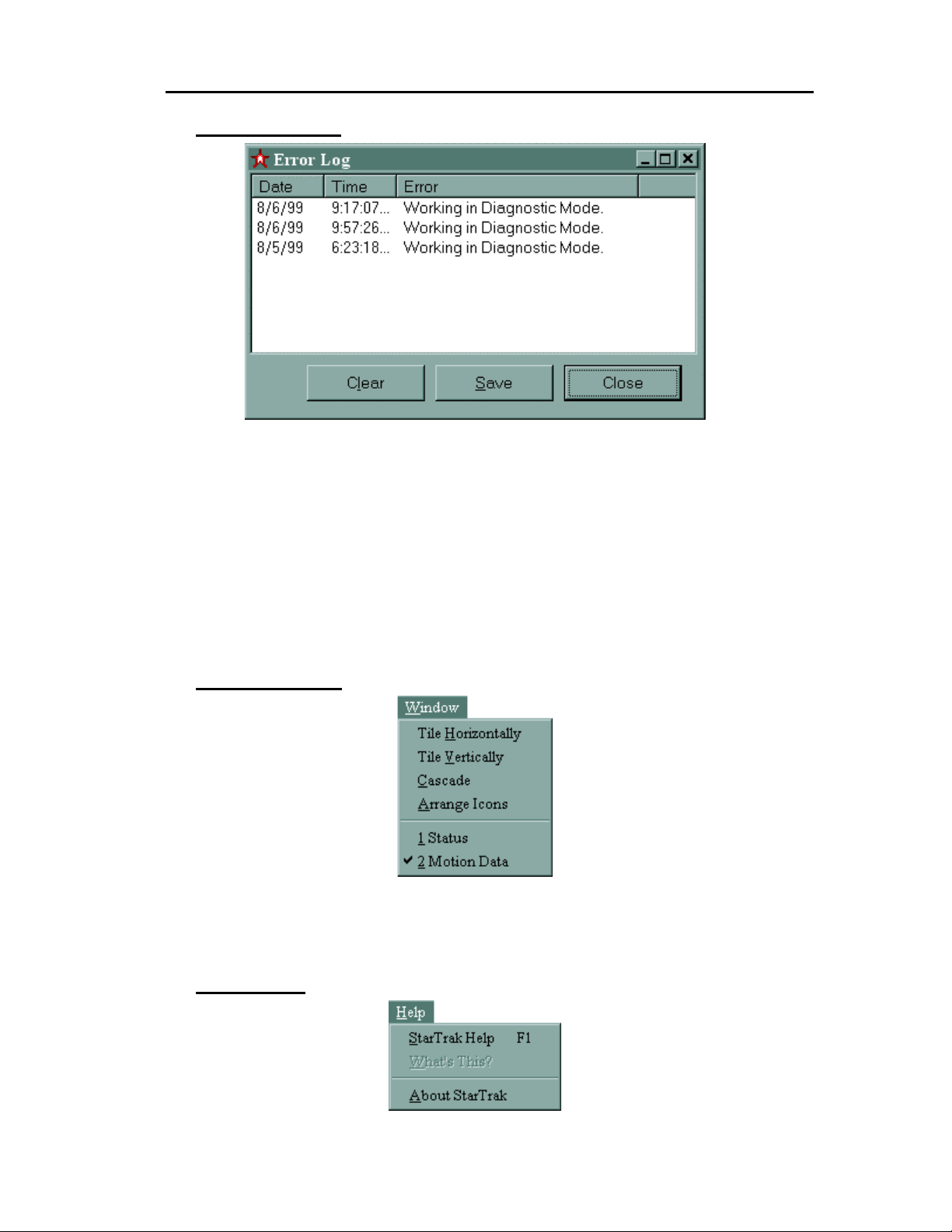
Figure 5- 2, Error Log Display
The Error Log Display may be selected from the View Menu, or by clicking on the Main
Window’s Status Bar, when an error m es s age is displaye d ther e .
The Error Log window lists time, date and descriptions of all StarTrak system in historical
order. If the list length exceeds the windo w size, a scroll bar is provide d. The lis t of error s ma y
be cleared with the “Clear” button or saved in a file with the “ Save” butt on. If the “ Save” butt on
is pressed, the log filename and the path will be requested. The “Close” button closes the Error
Log window.
Window Menu
The “Window” m enu contains choices ass ociated with m anaging the windows in the StarT rak
program’s workspace.
Help Menu
System Operation5-56
Page 60
Star★★★★Trak User Guide v001B
The “Help” menu contains choices for getting help with your StarTrak system.
• “StarTrak Help” launches the online version of this document. This can also be launched by
typing the F1 key.
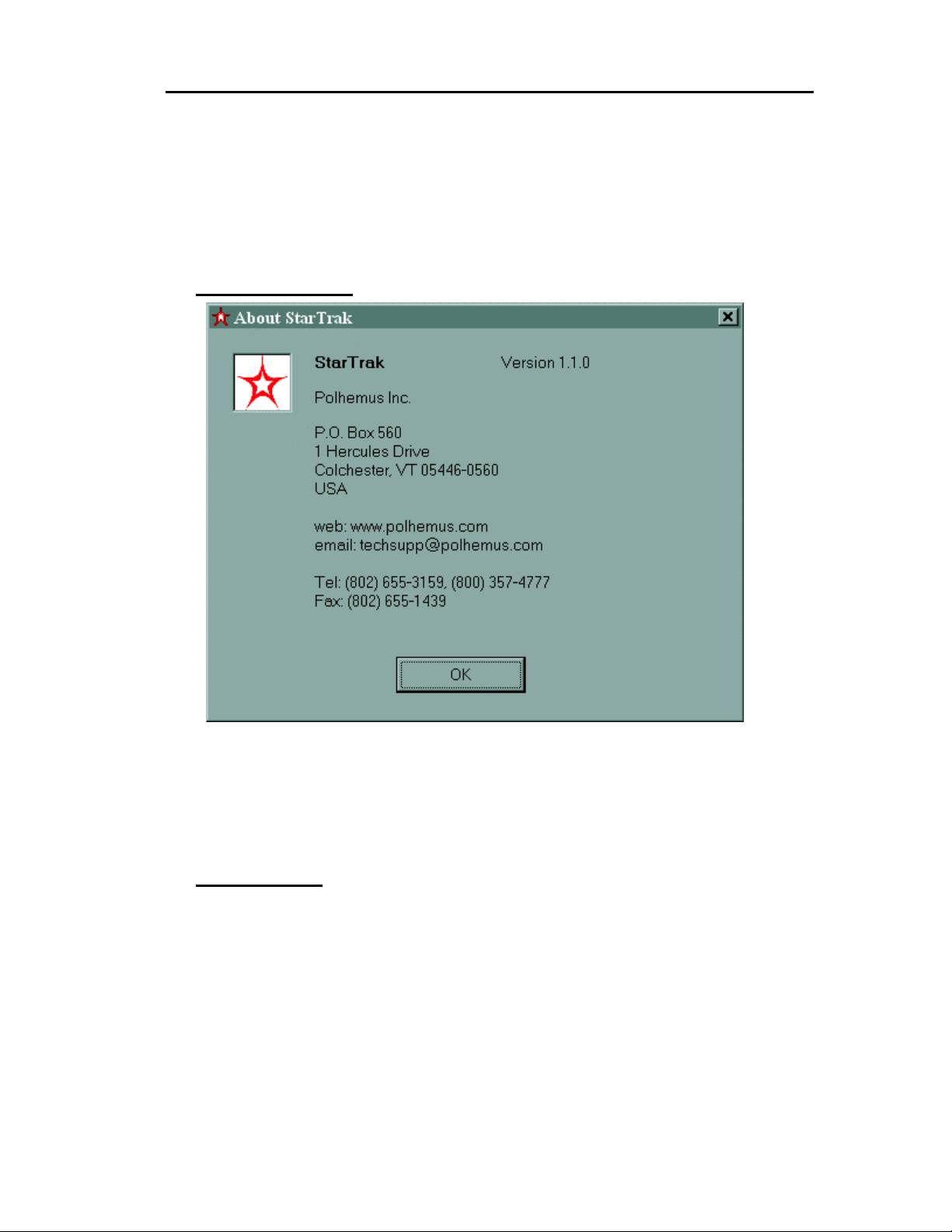
• “About StarTrak” displays version information for your StarTrak and Polhemus contact
information.
About StarTrak
5.3 S
TATUS WINDOW
Introduction
The System Status window is alwa ys displayed within th e main StarTrak application window
and provides basic c ontrol and monitoring f unctions for the StarTrak m otion capture system .
Control buttons are located at the bottom of the window while status and configuration
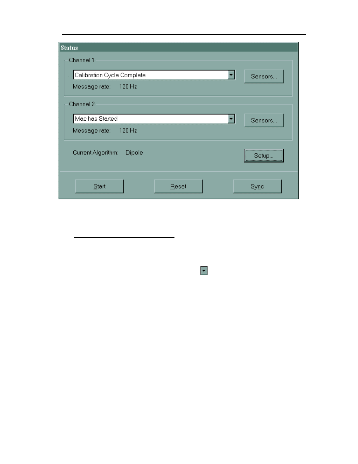
information is displayed in the upper part of the window. See Figure 5-3 below.
System Operation 5-57
Page 61
Star★★★★Trak User Guide v001B
Figure 5- 3, Status Window
Channel Status Messages
System messages are dis played in the list boxes for both C hannel 1 and Channel 2. Thes e
messages reflect oper ational s tates of th e StarPak and of the Med ia Ac cess Unit ( MAC). O nly
the latest message is displayed in the box. Up to 20 previous messages, listed in order of
reception, may be displayed by selecting the list control
Channel status messages are defined as follows:
"Mac NULL Message" .........................................No MAC is installed in the
"Mac has Started" ................................................MAC board is started and
"BP Available"......................................................StarPak powered up and
"BP Sensor Configuration" ..................................StarPak has reported active
to the right of the list box.
StarServe.
waiting for comm unication wit h
StarPak.
ready.
sensors detected.
"Starting BP SensorA Characterization Xfr" ........ StarPak has started tra nsfer of
even sensor characterization
data to the MAC.
System Operation5-58
Page 62

Star★★★★Trak User Guide v001B
"BP SensorA Characterization Xfer Complete" .. StarPak has completed
transfer of even sensor
characterization data to the
MAC.
"Starting BP SensorB Characterization Xfr" ........ StarPak has started tra nsfer of
odd sensor characterization
data to the MAC.
"BP SensorB Characterization Xfer Complete" .. StarPak has completed
transfer of odd sensor
characterization data to the
MAC.
"Mac Characterization Xfr Ready" ......................MAC has received all sensor
characterization data from the
StarPak and is starting transfer
to the StarServe.
"Mac Characterization Xfr Done" ........................MAC has completed transfer
of all sensor characterization
data to the StarServe.
"Calibration Cycle Started"...................................Calibration process has
started.
"Calibration Cycle Complete"...............................Calibration complete. The
system should now be tr ack ing
motion.
Channel Message Rate
The StarPak data rate is displayed beneath each channel’s status message list box. The
displayed value is in “Hert z” or messages per second . Normally, this value is 120 Hz, but if
there are other applications running on the StarServe, this number may be lower.
System Operation 5-59
Page 63
Star★★★★Trak User Guide v001B
Channel Sensors View
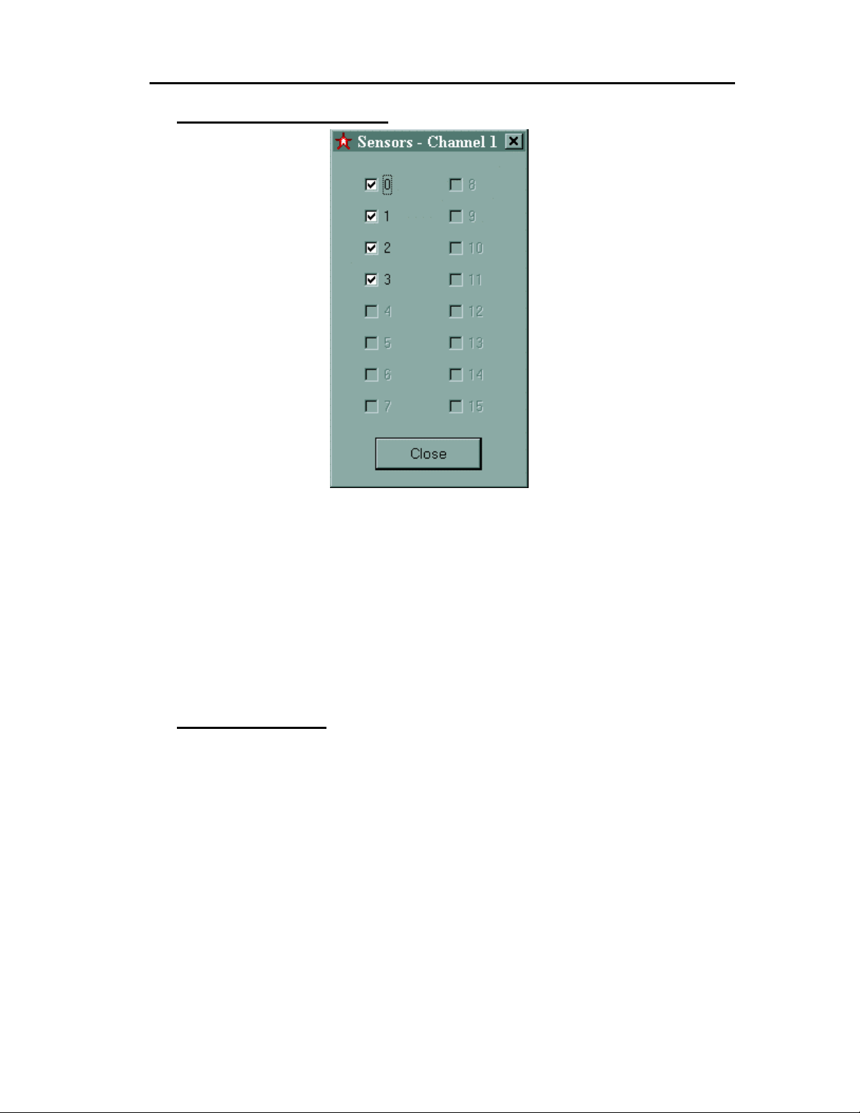
From the Status view, the Channel Sensors view is displayed by clicking on the “Sensors”
button to the side of each channel mess age l ist . E ac h p oten ti al se ns or (r ecei ver) att ac hed to a
StarPak is assigne d a checkbox. If a sensor is not attac hed or not functioning correctly, the
corresponding checkbox will be disabled. Sensor data display in the Motion Data and
Diagnostic views is control led by checking or unchecking th e active sensor check boxes. Data
will not be displa yed for unc hec ked s ensors . Check ing or unc heck ing an active s ens or box wil l
immediately enable or display that sensor’s data in any open Motion Data or Diagnostic views.
Note: Unchecking an act ive sensor box will
network connection.
disable export of that sensor s data over the
not
Control Buttons
Start
Selecting the “START” button initiates the startup of StarTrak system components and
establishes the communications link between the server and the StarPak. The StarServe
internal MAC unit is loaded autom atically with its operating soft ware and started. S imilarly the
table used to generate the Star Drive excitation is loaded and started.
Reset
The “Reset” button commands the StarPak(s) to reset but maintains the communications link.
System Operation5-60
Page 64
Star★★★★Trak User Guide v001B
Sync
The “Sync” button comm ands the MAC to issue a precisely tim ed pulse to the StarPak (s) via
tether to synchronize receiver data collection with the transmitted magnetic field.
5.4 D
ATA VIEWS
Data Menu
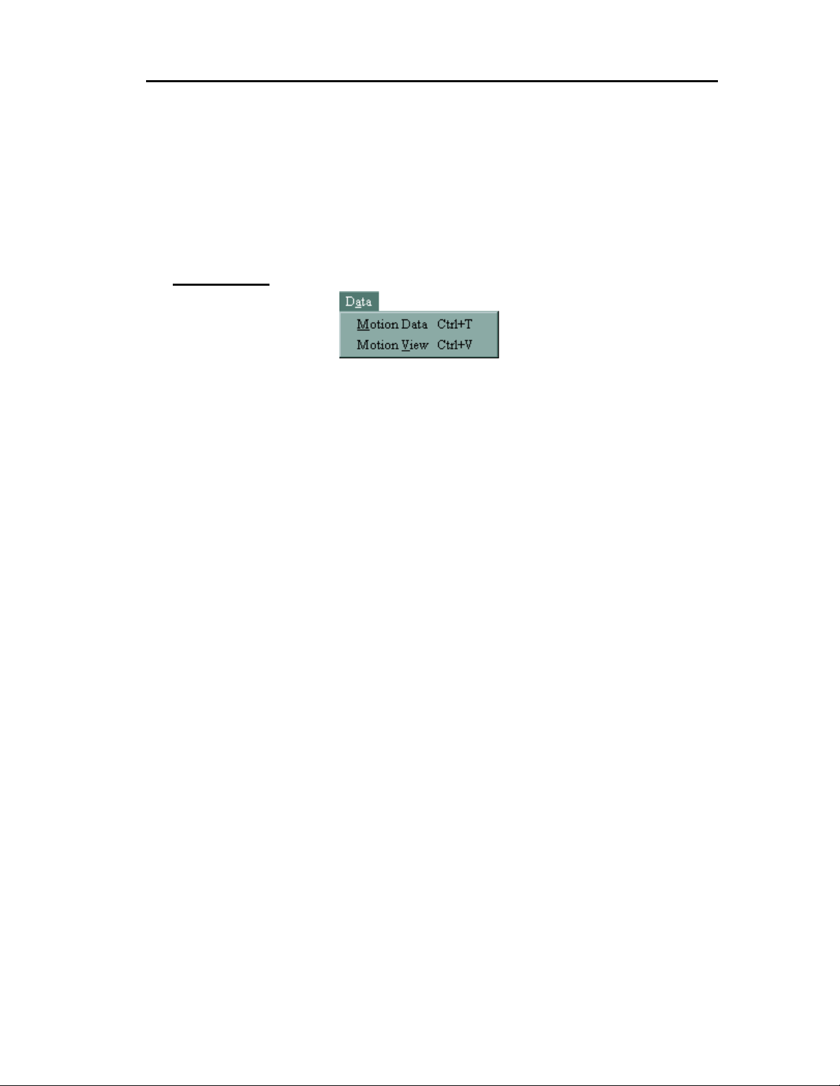
The “Data” menu contains choices for viewing motion data (Position & Orientation data)
reported by the receivers worn by the performer.
“Motion Data” presents P&O data for each receiver in tabular format.
“Motion View” presents positio n data only for each receiver in a graphical form at. Orientation
data is not available in this view.
System Operation 5-61
Page 65
Star★★★★Trak User Guide v001B
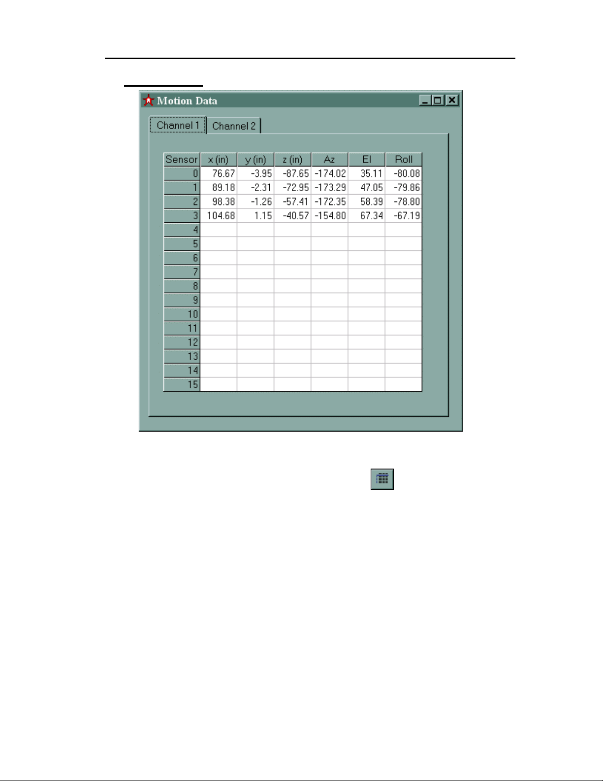
Motion Data
Figure 5- 4, Motion Data Display
Select the Motion Data item f rom the Data menu or selec t the icon from the T ool Bar to
invoke the Motion Data window (Figure 5-4). This window presents calculated position and
orientation data for any active receiver on channel 1 or channel 2. Position information is
displayed in inch es or cent imeter s depending o n the pref erence se lected i n the Form at T ab of
the Options view. (See section 5. 6). Orie ntation is displa yed in Euler a ngles. From left to right,
the columns are X, Y, Z, Azimuth, Elevation, and Roll.
Polhemus uses an AEROSPACE standard coordinate system. This is a right-handed
coordinate system where +Z is down; +X and +Y are defined during the mapping process.
Azimuth, Elevation, and Roll are 0, 0, 0 when a receiver is in l ine with th e +X axis , and the f lat
part of the receiver is facing downward. T he receiver cable is considered the 'tail' and c omes
out the rear (-X side) of the receiver . Converting fr om Azimuth, Elevation, and Roll to another
standard is a topic covered in the programmer's API, available from customer service.
System Operation5-62
Page 66
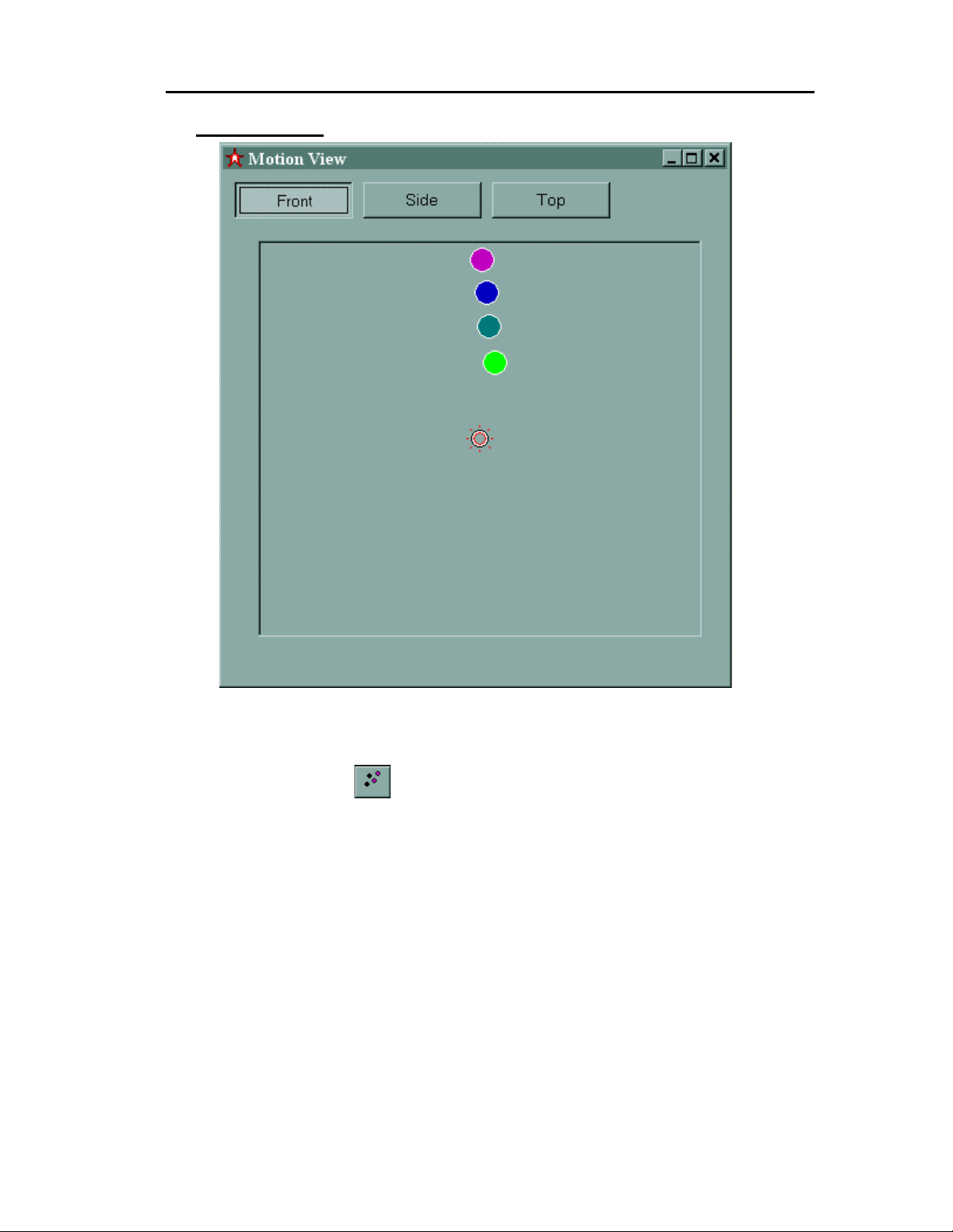
Motion View
Star★★★★Trak User Guide v001B
Figure 5- 5 Motion View Window
For a quick graphical pe ek of the receivers on the perform er, select “Motion View” from the
Data Menu item or se lect the
displays active sensor s (re ceivers ) as color ed c ircles withi n a pr edef ined 15 ’ x 15 ’ x 1 5’ m otion
capture area. Circles outlined in white represent sensors (receivers) from Channel 1, and
sensors (receivers) from channel 2 are outlined in black. The Motion View displays only
position
One of three “points of view” may be selected: (1) Front, (2) Side and (3) Top. In each case the
red, stationary ball represents the transmitter (Long Ranger or Super Nova). For the Front view
the transmitter is located in back of the receivers (eye level in the case of a Long Ranger).
NOTE: The calibration table algorit hm does not necessarily compensate receiver s that go to
the physical edges of a calibrat ed volume. Occasional erratic per formance can be noted in
receivers at such edges since they ma y encounter the uncalibrated r egion. Please note that
this applies to all directions of the volume, i.e. X, Y, and Z.
data. Orientation is not available here.
icon from the Tool B ar. T he windo w prese nted ( Figure 5-5)
System Operation 5-63
Page 67
Star★★★★Trak User Guide v001B
5.5 D
IAGNOSTIC VIEWS
Diagnostics Menu
The “Diagnostics” menu contains choices for troubleshooting your StarTrak system.
• “Magnetic Fields” displays unprocessed sensor data collected by the StarPak.
• “Characterization Data” displays factory measured data stored in each active receiver.
• “Calibration Data” displays calibration responses generated by the StarPak electronics.
Magnetic Field Data
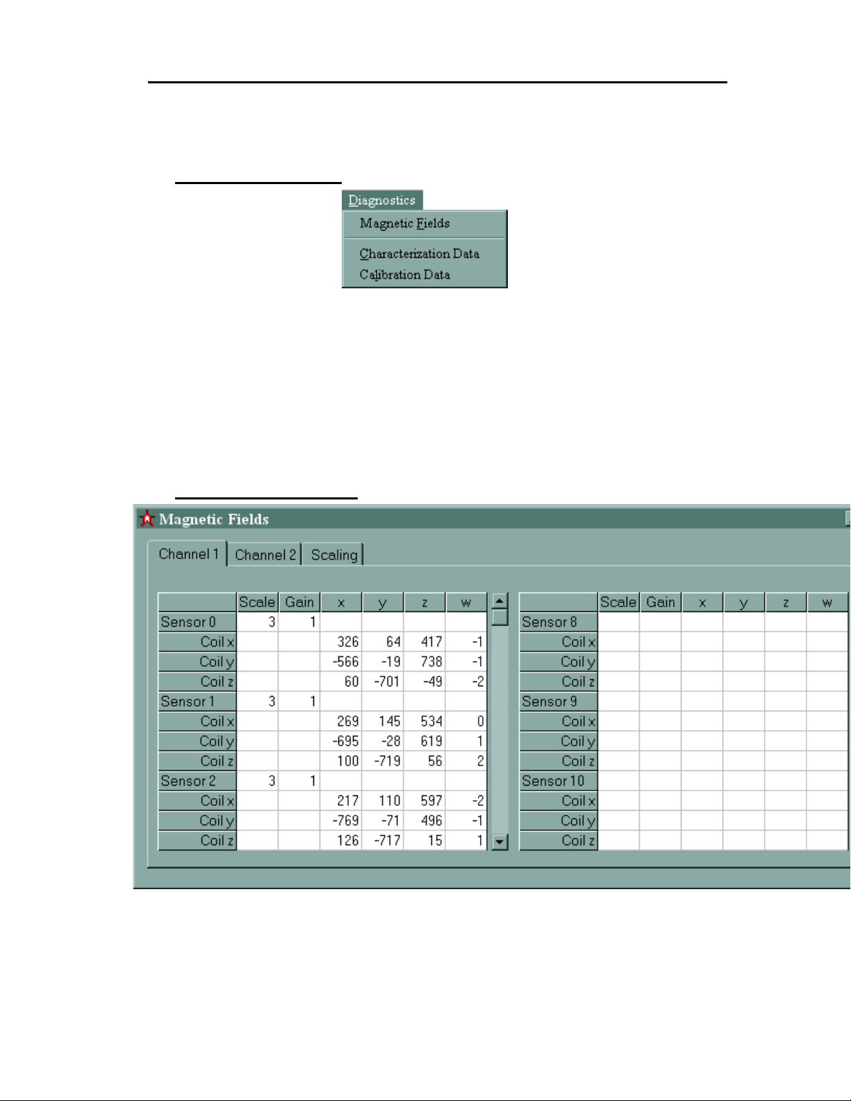
Figure 5- 6 Magnetic Field Data Window
System Operation5-64
Page 68
Star★★★★Trak User Guide v001B
To launch the magnet ic field dat a window sel ect “Magne tic Fields” from the Diagnostics Menu
or select the
shows the unprocessed receiver dat a collecte d by the St arPak (s). The data are only us eful for
system diagnostics and troubleshooting.
icon from the T ool Bar. The Mag netic Field data wind ow vie w (Figur e 5-6)
Characterization Data
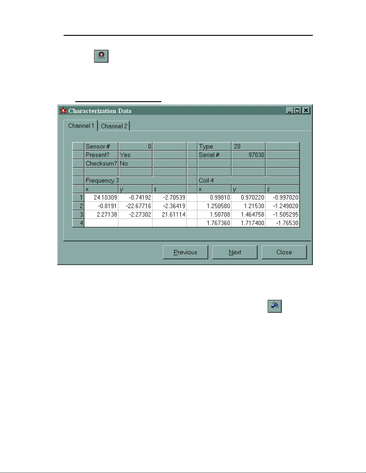
Figure 5- 7 Characterization Data Window
The characterization data window (Figure 5-7) is displayed upon the selection of the
“Characterization Data” list item from the Diagnostics Menu, or by se lecti ng t he
the Tool Bar. This window reflects fa ctory measured data store d in every act ive receiver. This
data includes the receiver serial number and coil responses to excitation frequencies. Figure 57 above shows what the coil response characterization data should look like.
Channel 1 or Channel 2 characterization data may be displayed. To increment through the
available receiver s, select the “next” button. To decrement through th e sensor list, se lect the
“previous” button. The “cancel” button closes this window.
System Operation 5-65
icon from
Page 69
Star★★★★Trak User Guide v001B
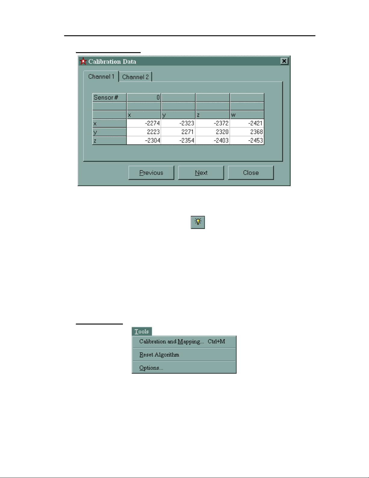
Calibration Data
Figure 5- 8 Calibration Data Window
The calibration da ta win dow (F i gure 5- 8) is o bta ine d by selecting the “Cal ibr at io n Dat a” choice
from the Diagnostics Menu or by selecting the
reflects coil and frequency responses to a precise signal generated on board the StarPak.
Figure 5-8 above shows what these responses should look like.
Channel 1 or Channel 2 c ali brat ion dat a m ay be disp la yed. T o increm ent thr ough t he a vaila ble
receivers, select t he “next” button. T o decrement thr ough the sensor lis t, select the “ previous”
button. The “cancel” button closes this window.
5.6 T
OOLS
icon from the Tool Bar. This window
Tools Menu
The “Tools” m enu contains choices for a variety of useful to ols for operating, calibrating, an d
characterizing your StarTrak system.
• “Calibration and Mappi ng” launches the “Map Setup” view, the first step in calibrating your
environment.
• “Reset Algorithm” restarts the P&O algorithm.
System Operation5-66
Page 70

Star★★★★Trak User Guide v001B
• “Options” launches the StarTrak application’s main options dialog. All configurable settings
for the application are accessed here.
Reset Algorithm
Selecting the “Reset Algor ithm ” lis t item r estarts the P&O al gorit hm . Resetting this algor ithm is
rarely required, but the option is provided for troubleshooting purposes.
Calibration and Mapping
Introduction
For an accurate representation of a receiver’s position and orientation within a volume, the
volume must be calibrated. Start the calibration process by selecting “Calibration and Mapping”
choice from the T ools Menu, or by selecting the
Environment Model chapter for a full discussion of the calibration (mapping) process.
icon from the Tool Bar. Refer to t he
System Operation 5-67
Page 71
Star★★★★Trak User Guide v001B
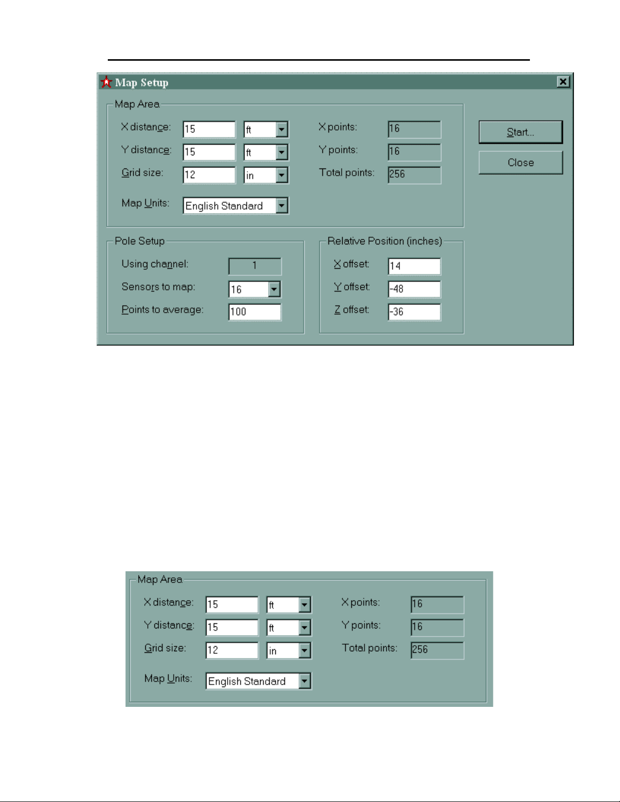
Figure 5- 9, Map Setup Window
The “Map Setup” windo w ( F igur e 5- 9) provides a means f or inputt in g map specific data prior to
starting the calibration process. Three frames require input: “Map Area,” “Pole Setup” and
“Relative Position.”
Measurements input into this view can be expressed in ei ther metric or English units . Select
the system you wish to use with the “Map U nits” selectio n, found in the “Ma p Area” section of
the view. Depending on the system selected here, e ach input meas urement ma y be specified
in either feet/inches (for English) or meters/centimeters for metric.
See “Define the Map ping Grid” an d “Map Setup” f or a detailed explanatio n of how to use th is
view.
Map Area
System Operation5-68
Page 72
Star★★★★Trak User Guide v001B
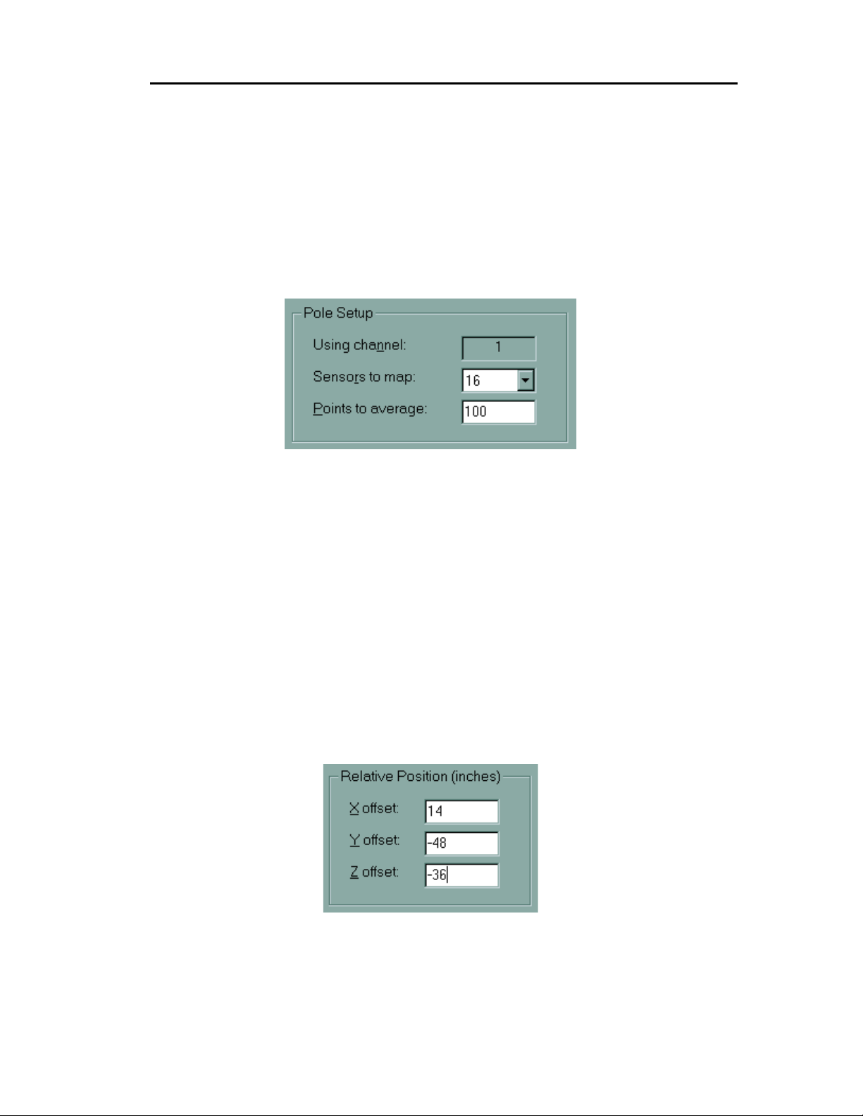
Specify the volume of the area to be mappe d by entering values in the “X dis tance” and “Y
distance” fields.
The “Grid size” field is used to sp ecif y the d istance between points to be m apped. S ee “ Define
the Mapping Grid” for a detailed explanation of the use of this field.
Use the “Map Units” f ield to spec ify En glish Stan dard or Metr ic un its for ex pressing the X - and
Y- distances.
Pole Setup
The “Pole Setup” f rame is used to specify mapping par ameters that relate to the calibrat ion
fixture.
The fixture uses a StarPack on Channel 1 only.
It can be configured to use either 8 or 16 sensors to gather data. Configur e this by using the
“Sensors to map” field.
The “Points to Average” f ield defines how much data is g athered at each point. The default
value here is 100 f rames. That is, one hundred data samples will be t aken and averaged at
each grid location to ac quire a calibr ation table value. The 100-frame def ault value should be
satisfactory i n most circumstances.
See “Map Setup” for a detailed explanation of how to use these fields.
Relative Position
The “Relative Pos ition” fram e is used to specify the measured off set distances between the
center of the transm itter and the first calibration p oint. See “Define the Mappin g Grid” for an
explanation of how to measure these distances.
System Operation 5-69
Page 73
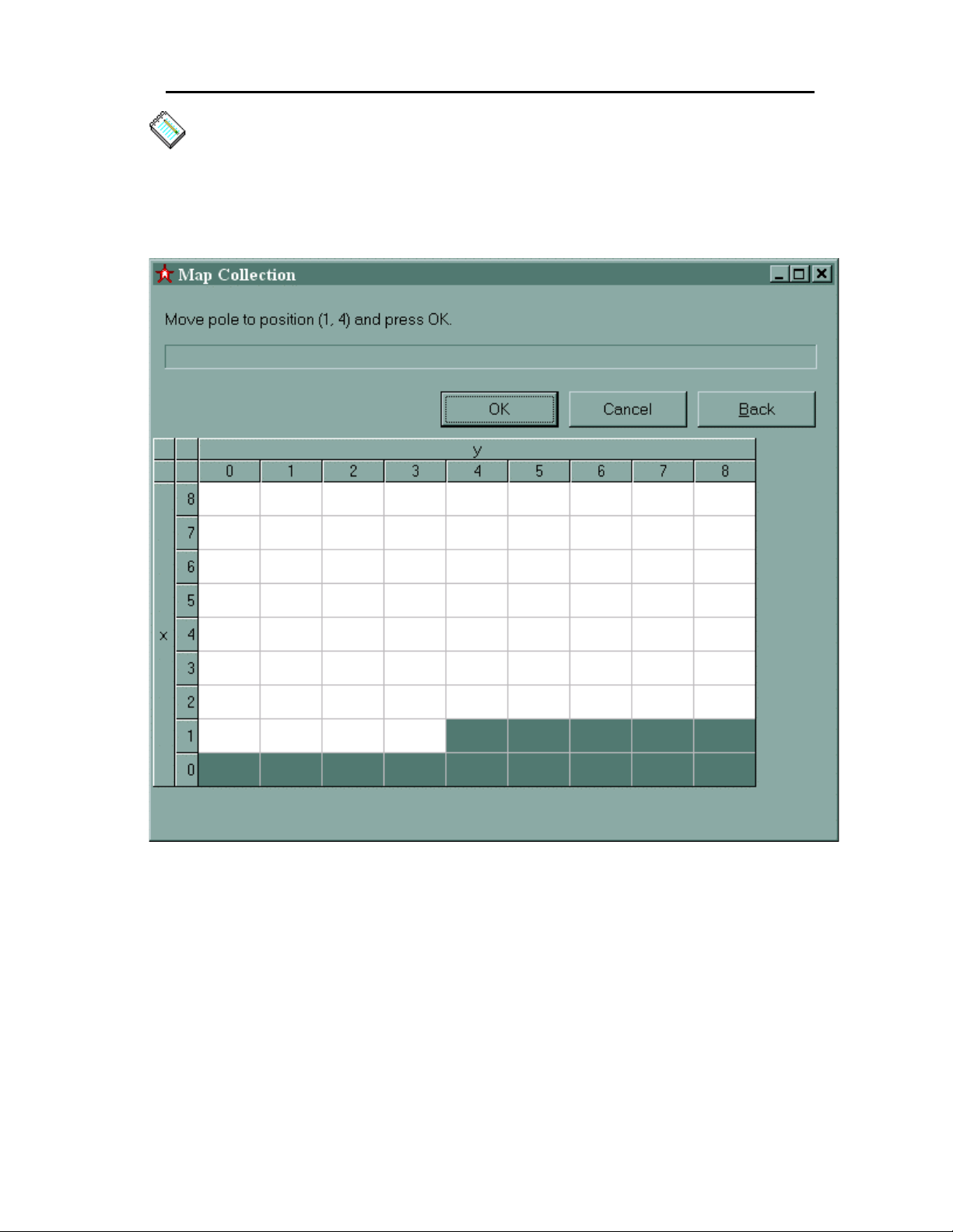
Star★★★★Trak User Guide v001B
Note: In version 1.0, the units of measurement used to spec ify the distances in t he “X - ,”
“Y-“ and “Z offset” fields is a lways INCH ES. It is
field in the “Map Area” frame at the top of the view.
affected by the setting of the “ Map Units”
not
Map Collection
Figure 5- 10, Map Collection Window
The “Map Collection” window (Figure 5-10 above) hosts the active portion of the mapping
process. It displays a grid r epresenting the (X, Y) dimension of the mapping volume. The Z
dimension is defined by the sensors affixed to the calibration pole. Cells within the grid are
filled with color as pointers to the next data collection position. Each square represents a
position at which the calibration po le will be placed and data c ollected. As the m ap collection
progresses, cells in the grid are filled in sequentially, in the “serpentine” pattern that the
calibration pole is moved through the mapping volume.
The progress bar abov e the m appin g gri d indic ates t he relat ive pro gres s of data coll ectio n a nd
averaging within an ( X, Y) cell of the mapping grid. T he rate of progres s is proport ional to the
System Operation5-70
Page 74

Star★★★★Trak User Guide v001B
number of points to be aver aged previously specified in the “pole setup” portion of the map
setup window .
There are three buttons associated with the control of the mapping process.
The “OK” button starts the collection and averaging proces s for one mapping cell. When all
data for a cell has been collected and averaged an audible “beep” is issued from the
StarServe, and the n ext square in the grid will be hi ghlighted, indicating the next p oint to be
collected.
The “Back” button allows for recollection of data at previous points . Click on this butt on onc e t o
re-collect data in the previous cell. Repeated clic king on this b utton will “back up” the proces s
to the desired cell. All cells “backed up” over will then be re-collected in sequence.
The “Cancel” button c omm its no data co llected to storag e, cl oses th e “ Map Coll ection” win dow
and brings the “Map Setup” window to the foreground.
See “Mapping Process ” for step-by-step instructions on the use of this view.
Options Window
Introduction
The Options windo w, accessed via the Tools Menu, allows for the configuration of StarServe
functions and features such as MAC boot and lo okup table files, Network configuration, P&O
algorithm, RF link configuration and system units of measure.
To use the Options window, select the settings you wish in any or all of the options tabs, a nd
click OK. To c ancel your select ions, click Cancel. To a pply your selections without dis missing
the Option s window, click Apply.
System Operation 5-71
Page 75
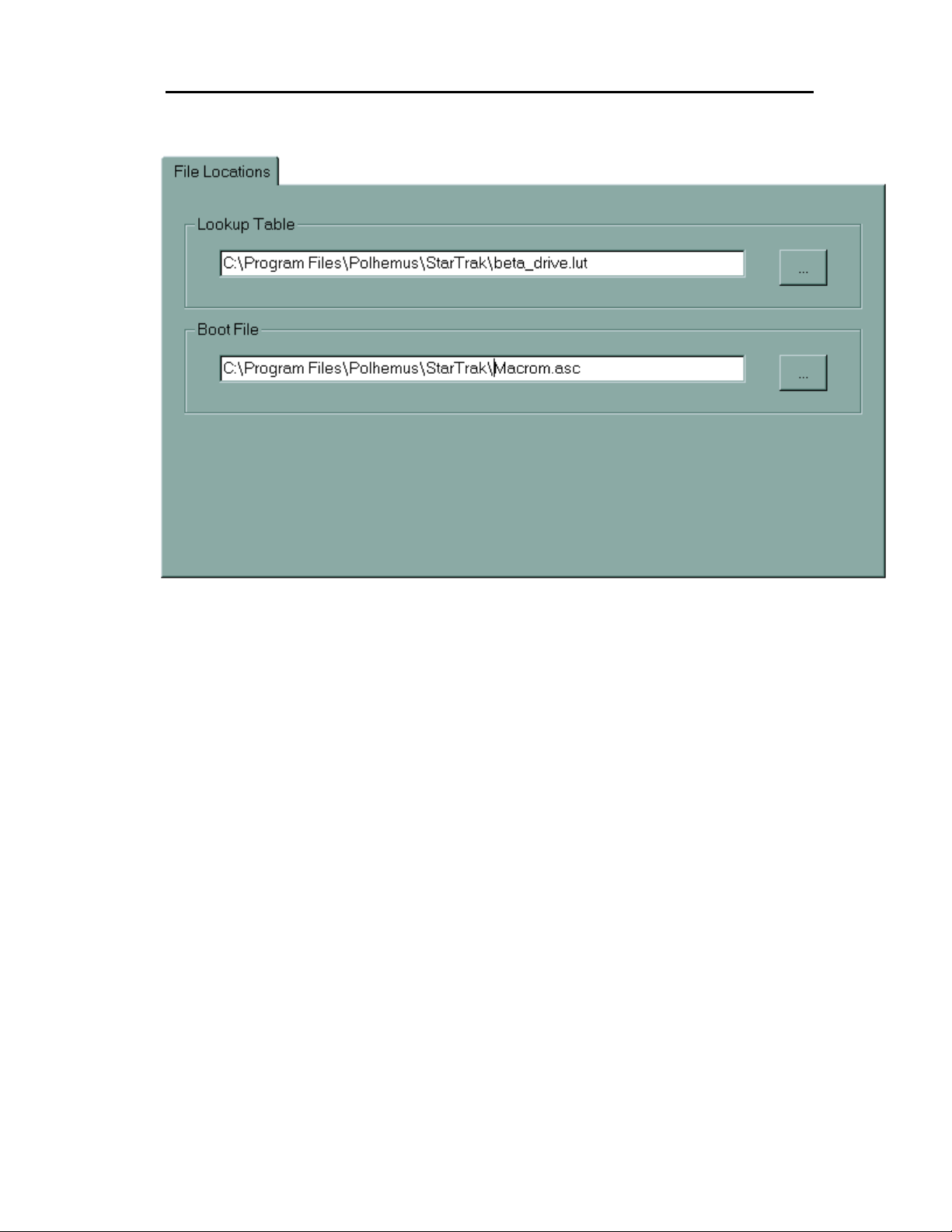
Star★★★★Trak User Guide v001B
File Locations Tab
Figure 5- 11 File Location Options Tab
There are two primary startup files used b y the Media Acc ess Contr oller with in the Star Server.
Selecting this ta b displays the name of each f ile. Searching f or and sp ecifying eac h filenam e
is possible through corresponding edit boxes and pop up dialog boxes.
As will all of the Opti ons wind o w ta bs, s el ec tio ns may be applied b y clic king “OK” or “Appl y,” or
discarded by clicking “Cancel.” Clicking “OK” will also dismiss the Options Window.
System Operation5-72
Page 76
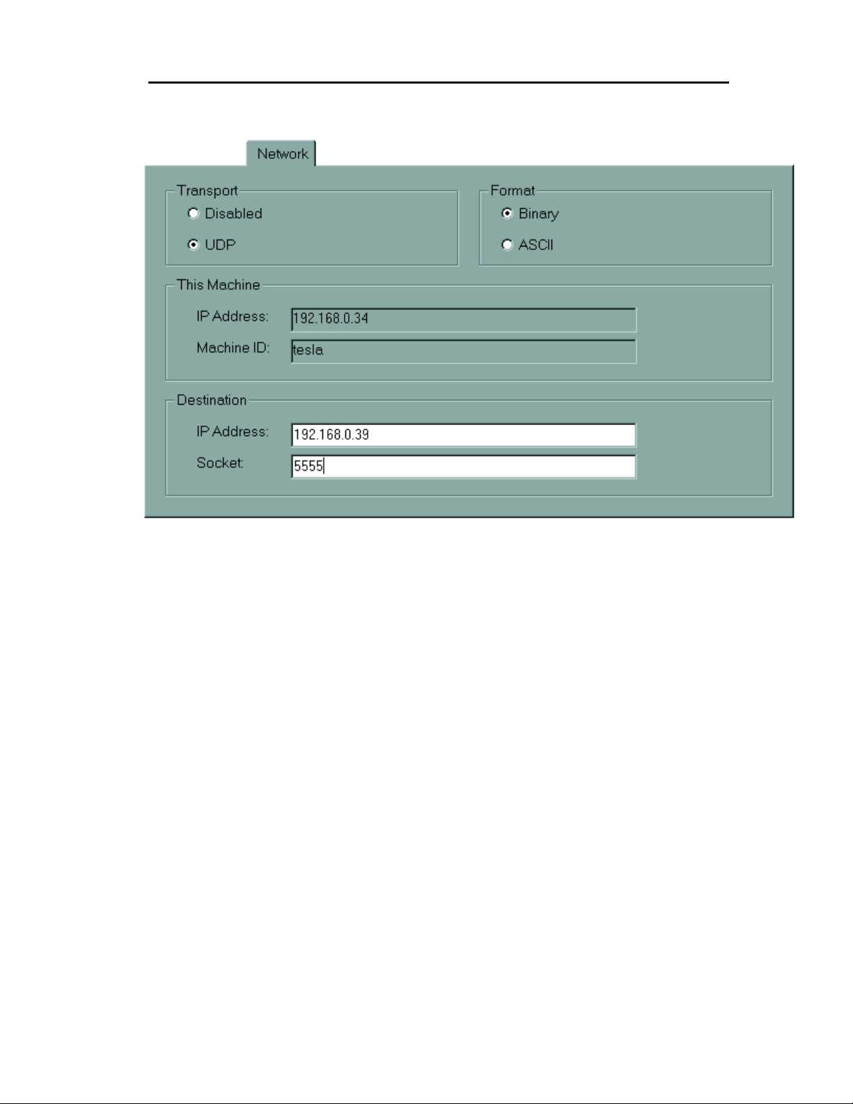
Network Tab
Star★★★★Trak User Guide v001B
Figure 5- 12 Network Configuration Options Tab
If motion data is to be exported, the Network configuration tab is used to enable the UDP
transport. set the network transport protocol ma y be specified as well as th e data format and
the destination address.
When the UDP transport is enabled, other transport configuration parameters must be
specified.
First, the format of the exported data must be specified. Typically, the binary format is
preferable because it is more compact and gives better performance. However, the ASCII
format may be preferred occasionally when a human-readable form is desired.
The destination IP is the address of the m achine l istenin g to the Star Ser ver. This addr ess is of
the form aaa.bbb.ccc.ddd where a, b, c, and d are numbers from 0 to 255.. To broadcast
motion data to all computers on the network, set the destination to 255.255.255.255.
Broadcasting can put a heavy load o n the network; it is not recomm ended for networks that
also have other purposes.
The Destination Socket is a unique number that needs to match the socket used by the
machine listening to the StarS erve. This soc ket number ref ers to the UDP port num ber and is
an integer between 1025 and 32767.
As a rule of thumb, the source and destination machines should have similar IP addresses. For
example, if the destination machine’s address is 128.0.0.1, the source machine’s address
should be 128.0.0.x where x is between 1 and 254.
System Operation 5-73
Page 77
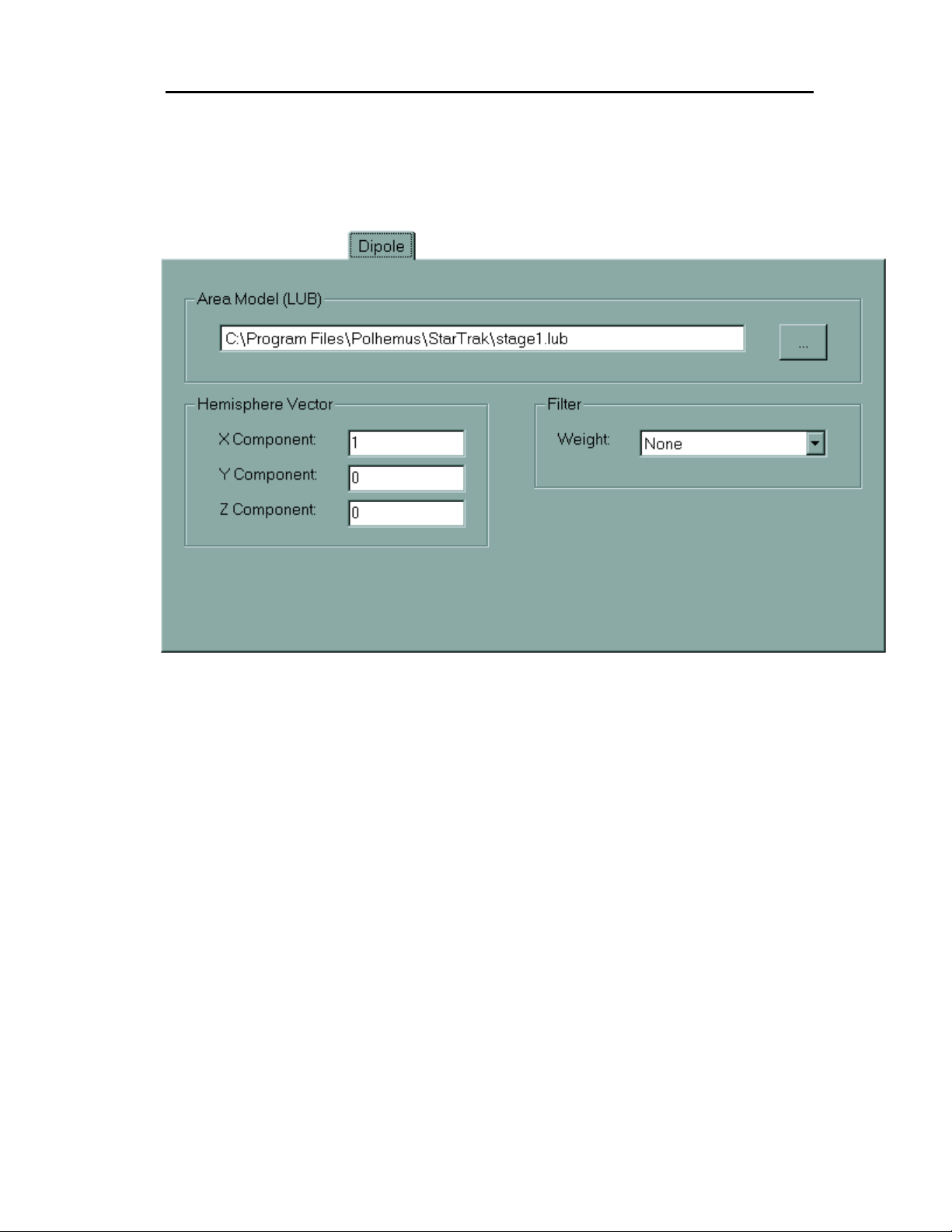
Star★★★★Trak User Guide v001B
As will all of the Opti ons wind o w ta bs, s el ec tio ns may be applied b y clic king “OK” or “Appl y,” or
discarded by clicking “Cancel.” Clicking “OK” will also dismiss the Options Window.
Dipole Tab
Figure 5- 13, Dipole Settings Options Tab
The Dipole Settings tab (Figure 5-13) is used to configure the Dipole P&O algorithm that
StarTrak employs. The configurable parameters are described below.
Area Model
The Area Model is the Look-up Block (.LUB) f ile t hat is c reated by the m appin g proc es s . When
no file is specif ied here, the StarT rak’s P&O algorithm applies no com pensation for m agnetic
field distortions in the motion captur e area. Most in door environm ents in the presenc e of m etal
objects or construction require compensation. A typical installation will have only one Area
Model (produced b y performing the Mapping and C alibration procedure), but it is possible to
have more than one. The "Browse" button allows selection of the Area Model .LUB file.
See the “Environmental Model” chapter for step-by-step instructions on calibrating your
environment.
System Operation5-74
Page 78

Star★★★★Trak User Guide v001B
Filter
The Filter is a motion filter that may be needed to smooth performance. Filtering may be
disabled by selectin g “none” in this f ield, or medium or heavy filter ing may be sel ected. W hen
filtering is app lied, the Dipole P&O algor ithm will “smooth” its results to lessen the effects of
extremely quick movements or momentary glitches or distortions.
Hemisphere
The StarTrak system allows oper ation in one hemis phere at a time of cover age relative t o the
Long Ranger transmitter. The hemisphere command defines the desired hemisphere of
operation. Basicall y, the user should choose one side of the transmitter where the recei vers
will always be and s pecify that side as th e hemisphere of operat ion. There are s ix selections
and are as follows:
1, 0, 0 +X
-1, 0, 0 -X
0, 1, 0 +Y
0,-1, 0 -Y
0, 0, 1 +Z
0, 0, -1 -Z
The X, Y and Z components of the Hem isphere vector determ ine the base orient ations of the
three field components . T he default value of (1, 0 , 0) ind icates t hat the “ f or ward” hemisphere is
selected. This means that if the performer is standing in front of the transmitter, pos itive X is
straight ahead, positive Y is to the right, and positive Z is straight down.
As will all of the Opti ons wind o w ta bs, s el ec tio ns may be applied b y clic king “OK” or “Appl y,” or
discarded by clicking “Cancel.” Clicking “OK” will also dismiss the Options Window.
System Operation 5-75
Page 79
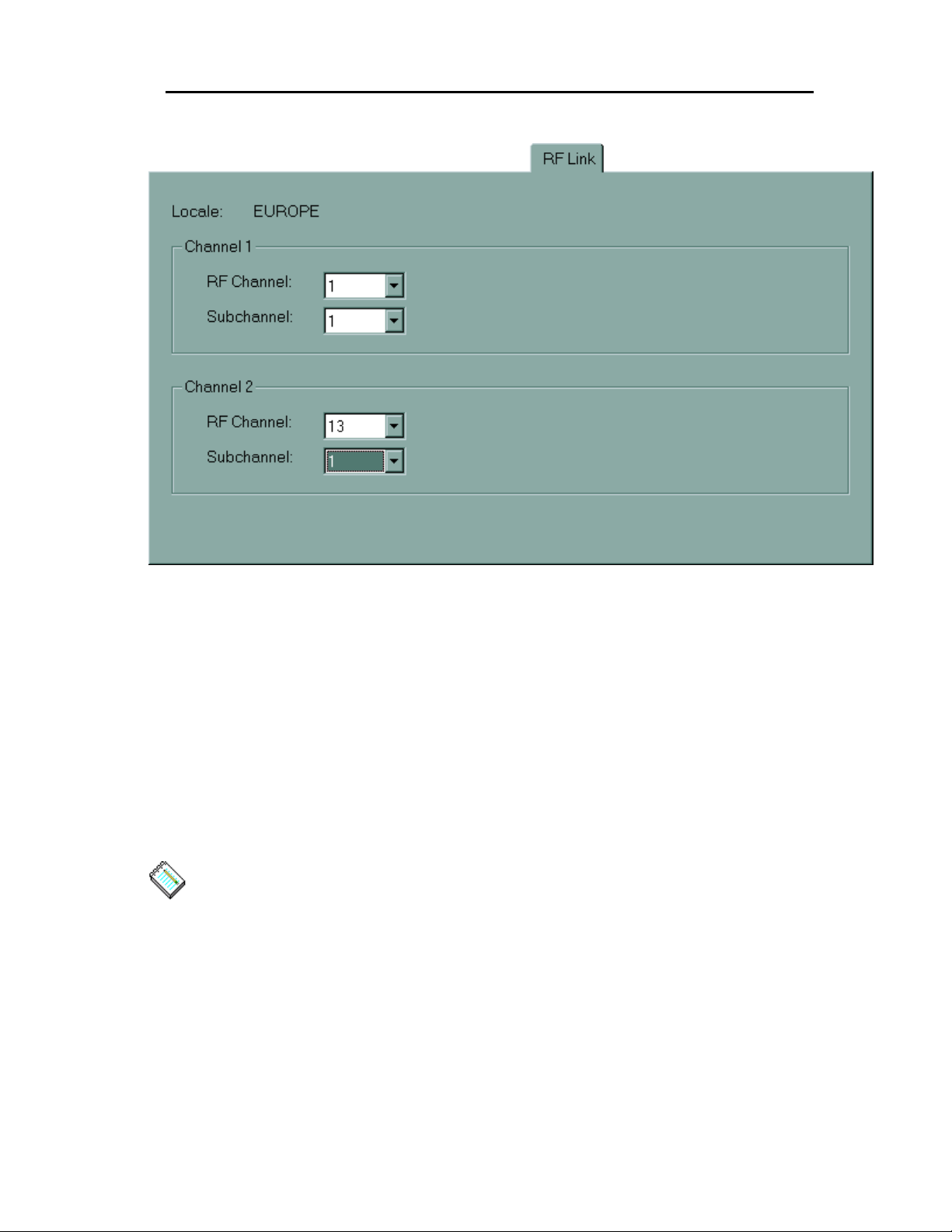
Star★★★★Trak User Guide v001B
RF Link Tab
Figure 5- 14, RF Link Options Tab
Selection of the RF L ink Tab ( Figure 5-14) dis plays and a llows m odification of each StarPak ’s
wireless channel and s ub channel. Select the RF ch annel and (spreading code) s ubchannel
from the appropriate dropdown lists. T here are 12 RF ch annels and 4 subc hannels to ch oose
from.
When two StarPaks are used, selection of the RF channels is critical. At least a 4 channel
separation (between the two StarPaks) must be observed for effective communication.
Additionally, channel 1 should never be used in a multi StarPak configuration.
As will all of the Opti ons wind o w ta bs, s el ec tio ns may be applied b y clic king “OK” or “Appl y,” or
discarded by clicking “Cancel.” Clicking “OK” will also dismiss the Options Window.
Note: The available RF channel selections are pre-programmed to according to
communications regulations in the country in which the StarTrak is deployed.
System Operation5-76
Page 80
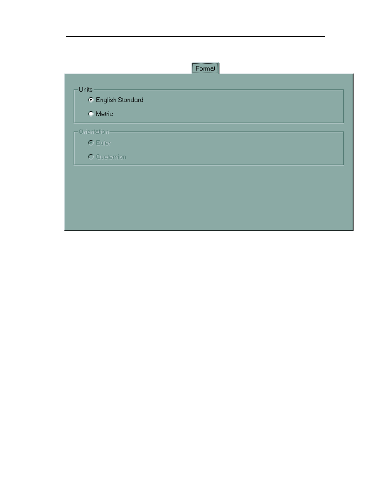
Format Tab
Star★★★★Trak User Guide v001B
Figure 5- 15, Format Options Tab
From the Format optio ns tab, you may select your n umeric system preferences . This setting
dictates the units in which the P&0 dat a will be displa yed in the Motion D ata view, as well as
the default units of measurement used throughout the StarTrak program.
As will all of the Opti ons wind o w ta bs, s el ec tio ns may be applied b y clic king “OK” or “Appl y,” or
discarded by clicking “Cancel.” Clicking “OK” will also dismiss the Options Window.
System Operation 5-77
Page 81

Star★★★★Trak User Guide v001B
6 Exporting Data
6.1 I
To export keyframed motion data over a network UDP connection, enable the UDP option in
the Network Tab of the O ptio ns v ie w. S ee t he N etwork Tab topic i n S ec tio n 5. 7. You mus t als o
set the IP address of the client machine, an d the UDP port num ber that the client process is
listening on. Make sure that the port number you select does not conflic t with other pr ocesses
that may be listening on the c lient mac hine. You m ay also specif y whether the m otion captur e
data will be exported in ASCII or BINARY. Binary is the most compact form and is
recommended for m inimum lag. However, ASCII m ay be preferable in certain circum stances
where it is necessary to examine the data visually.
Once enabled, the StarTrak system will begin exporting captured data immediately.
6.2 D
The format of each exported data frame is as follows:
NTRODUCTION
ATA FORMAT
Header: Frame 023 FrameSize 736 HeaderSize 056 RecordSize 085
<cr><lf>
Body: a011 <x pos> <Y pos> <Z pos> <Azimuth> <Elevation> <Roll>
<cr><lf>
Body: a111 <x pos> <Y pos> <Z pos> <Azimuth> <Elevation> <Roll>
<cr><lf>
Body: a211 <x pos> <Y pos> <Z pos> <Azimuth> <Elevation> <Roll>
<cr><lf>
Body: a311 <x pos> <Y pos> <Z pos> <Azimuth> <Elevation> <Roll>
<cr><lf>
Body: a012 <x pos> <Y pos> <Z pos> <Azimuth> <Elevation> <Roll>
<cr><lf>
Body: a112 <x pos> <Y pos> <Z pos> <Azimuth> <Elevation> <Roll>
<cr><lf>
Exporting Data6-78
Page 82

Star★★★★Trak User Guide v001B
Each frame of data consists of a header and a b ody. The h eader is a lways ASCII . The he ader
information consists of the following fields:
Frame Number: Integers from 0 to 999. Frame number rolls over at 999.
Frame Size: The number of bytes in the frame.
Header Size: The number of bytes in the header.
Record Size: The number of bytes in each record of the body portion of the frame.
The body of the frame contains position/orientation records for each active sensor. Each
record begins with an encoded ASCII 4-character sequence that indicates the following
information about the record
:
StarTrak identifier: This is always the lower-case letter a.
Sensor number: Hexadecimal number 0 through F
New Data Flag: Always 1.
Channel Number: 1 or 2.
Next, each record contains position and orientation data f iel ds. The P&O data ma y be A SCII or
binary, depending on the prefer ences set in the Op tions tab. The X, Y, Z positio n data m ay be
expressed in either C M or INCHES, depending of pref erences set in the Form at Tab in the
Options View. Orient ati on da ta is ex pres s ed as Eu ler An gl es a zimuth, elevation, and rol l. Euler
angles are expressed in degrees .
Figure 6.1 shows sample ASCII data of four sensors on each channel.
Frame 023 FrameSize 736 HeaderSize 056 RecordSize 085<cr><lf>
a011 -1.12345E-01 -2.12345E-02 -3.12345E-03 -0.12345E-00 -1.12345E-01 -
2.12345E-03 <cr><lf>
a111 1.12345E-01 2.12345E+02 3.12345E+03 0.12345E+00 1.12345E+01
2.12345E+03 <cr><lf>
a211 -1.12345E-01 -2.12345E-02 -3.12345E-03 -0.12345E-00 -1.12345E-01 -
2.12345E-03 <cr><lf>
a311 1.12345E-01 2.12345E+02 3.12345E+03 0.12345E+00 1.12345E+01
2.12345E+03 <cr><lf>
a012 -1.12345E-01 -2.12345E-02 -3.12345E-03 -0.12345E-00 -1.12345E-01 -
2.12345E-03 <cr><lf>
a112 1.12345E-01 2.12345E+02 3.12345E+03 0.12345E+00 1.12345E+01
2.12345E+03 <cr><lf>
a212 -1.12345E-01 -2.12345E-02 -3.12345E-03 -0.12345E-00 -1.12345E-01 -
2.12345E-03 <cr><lf>
Exporting Data 6-79
Page 83

Star★★★★Trak User Guide v001B
a312 1.12345E-01 2.12345E+02 3.12345E+03 0.12345E+00 1.12345E+01
2.12345E+03 <cr><lf>
Figure 6-1 Sample Data
Exporting Data6-80
Page 84

7 Maintenance
Star★★★★Trak User Guide v001B
7.1 I
The StarTrak s ystem contains sensitive electronic components that requ ire special attent ion.
Information on the saf est way to us e StarTrak , how to care for your system , creating the ideal
work environment and moving your system is included in this chapter.
7.2 M
Except as explained els ewhere in this m anual, do not attem pt to service the StarT rak system
yourself.
To avoid damage to the StarTrak system and monitor, use the correct type of alternating
current (AC) power 90 – 230V and 50/60Hz
To prevent electric shock , plug your St arT rak 's power c able int o a pr operl y gro unded e lectrica l
outlet. If you use an extension cable, use a 3-prong extension cable. Do not handle the
transmitter(s) while operating.
If the StarTrak is dropped or damaged, contact Polhemus Incorporated for technical
assistance.
NTRODUCTION
AINTAINING A SAFE WORK ENVIRONMENT
7.3 C
Before cleaning your StarTrak, unplug it. Use a cloth dampened with water or cleaning
solution. Do not apply liquid, thinner, oil, petroleum or aerosol cleaners directly to the StarTrak.
Do not probe the inside of your StarTrak; the power supply contains high voltage.
7.4 T
When moving the StarTrak system, use the following precautions:
ARING FOR YOUR STARTRAK SYSTEM
RANSPORTING THE STARTRAK SYSTEM
Maintenance 7-81
Page 85

Star★★★★Trak User Guide v001B
• Turn off all components.
• Disconnect all cords and cables.
• Coil cables and tape them to the system unit.
• Repackage the StarTrak system in its original packing materials.
• Remember that the new site will require an environment modeling &
calibration and that the return of the system to its original operating site may
require re-calibration depending on the precision of the replacement of the
transmitter(s) from their original location.
Maintenance7-82
Page 86

8 Technical Support
Star★★★★Trak User Guide v001B
8.1 T
If you encounter a problem while us ing your StarT rak system pleas e try to note the s ymptom,
the software module that the problem occurred in (i.e., starmap.exe, startrak.exe,
dos4gw.exe), and what the configuration of the system was at the time the error occurred.
Then, call (800) 357-4777 (USA or CANADA) or (802) 655-3159, ext. 242, for Customer
Service. Our customer service engineers can provide assistance over the telephone. If the
problem requires any repairs, the Customer Service engineer will issue you a Return
Merchandise Authorization (RMA) number. We recommended keeping the original shipping
container for your St arTr ak in the event that it needs to be shipped or m oved. Pleas e do n ot
return any equipm ent without an RM A number, as it will not be ac cepted. If your equipm ent is
still under warranty, Polhem us will repair it free of charge according to the provisions of the
warranty as stated in Chapter 9. The proper return address is:
ECHNICAL SUPPORT
Polhemus Incorporated
1 Hercules Drive, P.O. Box 560
Colchester, Vermont 05446-0560
Telephone (voice): (802) 655-3159, or (800) 357-4777 (U.S. and Canada only)
Telephone (FAX): (802) 655-1439
E-mail (Technical Support): [email protected]
Web Home Page: http://www.polhemus.com
Technical Support 8-83
Page 87

Star★★★★Trak User Guide v001B
9 Important Information
9.1 W
Polhemus Incorporated (PI) warr ants that the S ystem shall be free from def ec ts in material and
workmanship for a period of one year from the date ownership of the System passes from PI to
Buyer. PI shall, up on notification within the warranty period , correct such defec ts by repair or
replacement with a l ike servic eable item at PI's option. This warr anty shall be co nsidered void
if the System is operated other than i n accorda nce with t he instruc tions in P I's User Ma nual or
is damaged by accident or mishandling. Parts or material that are clearly expendable or
subject to norm al wear beyond usef ulness within the warranty period suc h as lamps, fuses,
etc., are not covered by this warranty.
In the event any Syst em or portion thereof is defective, t he Buyer shall, within the warranty
period, notify PI in writing of the nature of the defect, under the direction of PI determine and
remove the defectiv e parts, ship such parts to PI. Upon determination b y PI that the parts or
Systems are defective and covered by the warranty set forth above, PI, at its option shall repair
or replace the same without cost to the Buyer. The Buyer shall pay all charges for
transportation and del iver y costs to PI's fact ory for def ecti ve parts where directe d to be se nt to
PI, and PI shall pay for transportation costs to the Buyer's facility for warranty replacement
parts and Systems . Removed parts covered by claim s under this warrant y shall become the
property of PI.
In the event that allege dly defective par ts are found not to be def ective, or ar e not cov ered by
warranty, Buyer agrees that PI may invoice Buyer for all reasonable expenses incurred in
inspecting, testing, r epairing and ret urning the System and that the Bu yer will pa y such costs
on being invoiced therefor . The Buyer shall bear the risk of loss or damage during transit in
such cases.
ARRANTY
& L
IABILITY
Any repaired or rep laced part of a S ystem shall be warranted f or the remain ing period of the
original warranty or thirty (30) days, whichever is longer. Warranties shall not apply to any
Systems which hav e been: repair ed or altered other than b y PI, ex cept when s o author ized in
writing by PI; used in an unauthorized or improper manner, or without following normal
operating procedures; or improperly maintained and where such activities in PI's sole
judgement, have adversel y affected the System. Neither shall warranties appl y in the case of
damage through accidents or acts of nature such as flood, earthquake, lightning, tornado,
typhoon, power surge or failure, environmental extremes, or other external causes.
Important Information9-84
Page 88

Star★★★★Trak User Guide v001B
PI does not warrant and spec ifically disclaim s the warranty of merc hantability of the products
or the warranty of fitness of the products for any partic ular purpose. PI mak es no warranties,
express or implied, except of title and a gains t paten t inf ringem ent, oth er than t hose s pec ific ally
set forth herein.
In no event shall PI be liable un der any circumstanc es for special incident al or consequentia l
damages, including, but not lim ited to loss of profits or r evenue. W ithout lim iting the forego ing,
PI's maximum liabilit y for damages for any cause whats oever, exclusive of claims fo r patent
infringement and regardless of the form of the action (including but not limited to contract
negligence or str ict liab il ity) shall be limited to buyer's actu al dir ec t damages, not to ex c eed t he
price of the goods upon which such liability is based.
9.2 I
Polhemus Incorporated (PI) shal l hav e the right at its own expense, to defend or at i ts op tio n to
settle, any claim, s uit or proceeding brought against t he Buyer on th e issue of infr ingement of
any United States pate nt by any product, or any part thereof, supplied by PI to Buyer under
this Agreement. PI s hall pay, subject to the l imitations hereinafter set forth in this paragra ph,
any final judgment entered against the Bu yer on such issue in any such suit or proceeding
defended by PI. PI at its sole option shall be rel ieved of the foregoing obligatio ns unless the
Buyer notified PI promptly in writing of any such claim, suit or proceedings, and at PI's
expense, gave PI proper and full inform ation and assista nce to settle an d/or defend any such
claim, suit or proceeding. If the product, or any part thereof, furnished by PI to the Buyer
becomes, or in the opinion of PI m ay become, the subj ect of any claim , suit or proce eding for
infringement of any United States patent, or in the event of an adjudication that such product or
part infringes any United States p atent, or if the use, lease or s ale of such product or par t is
enjoined, PI ma y, at its option and its expense: (a) procure for the B uyer the right under such
patent to use, lease or sell, as appropria te, such produc ts or part, or (b) r eplace such prod uct
or part, or (c) modif y such product, or p art, or (d) remove s uch product or p art and refund the
aggregate payments a nd transportation costs paid ther efore by the Buyer less a reasonable
sum for use, damage and obsol escence. PI s hall have no liabilit y for an y infringement ar ising
from: (i) the combination of such prod uct or part with a ny other produc t or part whether or not
furnished to Buyer by PI, or (ii) the modification of such product or part unless such
modification was made b y PI, or (iii) the use of such prod uct or part in practicing a ny process ,
or (iv) the furnish ing to the Buyer of any infor mation, data, service or a pplication assistance.
The Buyer shall hold PI harmless against any expense, judgment or loss for infringement of
any United States patents or tradem arks which results from PI's compliance with the Bu yer's
designs, specifications or instructi ons. PI shall not be liab le for an y costs or ex penses i ncurred
without PI's written authorizat ion and in no event s hall PI's total liability to the Buyer under, or
as a result of compliance with, the provisions of this paragraph exceed the aggregate sum paid
to PI by the Buyer f or the allegedly infringing produc t or part, exclusive of any r efund under
option (iv) above. The f or ego in g s tat es the ent ir e lia bi lity of PI, a nd the exclusive remedy of the
Buyer, with respect to any actual or alleged patent infringement by such product or part.
NDEMNITY AGAINST PATENT INFRINGEMENT
9.3 FCC S
This equipment has been tested and found to comply with the limits for a Class A digital
device, pursuant to part 1 5 of the FCC R ules. T hese lim its are des ign ed to pr ov ide reas onabl e
protection against inter ference when th e equipment is operated in a com mercial env ironment.
This equipment generates, uses , and can radiate radio frequency en ergy and, if not installe d
Important Information 9-85
TATEMENT
Page 89

Star★★★★Trak User Guide v001B
and used in accordance with instructions in this manual, may cause interference to
communications signals. Operation of this equipment in a residential area may cause
interference, in which case the user will be required to correct the interference at his own
expense. This device complies with Part 15 of the FCC Rules. Operation is subject to the
following two conditions: (1) this device must not cause harmful interference, and (2) this
device must accept any interference that may cause undesired operation.
RF Exposure For Wireless Option
WARNING: To satisfy FCC RF exposure requirements for mobile transmitting devices,
a separation distance of 20 cm or more should be maintained between the antenna of
this device and persons during device operation. To ensure compliance, operations at
closer than this distance is not recommended.
Important Information9-86
 Loading...