

Page 1
Date: April 15, 2005
Ver. : 1.1
V23D/V27D/V30D series
LCD-TV(NTSC)
Service Manual
Page 2

Table of contents
1. Precautions & Notice.......................................………………….3
2. Features & Specifications............................................………….5
3. Connection & Applications.........................................................10
4. Controls Location ........................................................................12
5. Remote Control. ..........................................................................13
6. Disassembly Instructions.............................................................15
7. Block Diagram..............................................................................20
8. Troubleshooting .................................................................……..21
9. Electronic Circuit Description................................................…27
10. Circuit Diagram....................................................…………….31
11. PCB Layout....................................................…………………56
12. Electrical Part List.................................................................... 65
13. Mechanical Disassembly............................................................67
Page 3
1. Precautions & Notice
1.1 Safety Precautions
1) Cleaning: Unplug the power cord from the AC outlet before cleaning the
product. Use a damp cloth to clean the product. Do not use liquid cleaners
or aerosol cleaners.
2) Heat sources: Keep the product away from heat sources such as radiators, heaters, stoves and
other heat-generating products (including amplifiers).
3) For added protection for this television equipment during a lightning storm,
or when it is left unattended and unused for long periods of time, unplug it
from the wall outlet and disconnect the antenna. This will prevent damage
to the equipment due to lightning and power-line surges.
4) If an outside antenna is connected to the television equipment, be sure the antenna system is
grounded so as to provide some protection against voltage surges.
5) An outside antenna system should not be located in the vicinity of overhead
power lines or other electric light or power circuits, or where it can fall into
such power lines or circuits. When installing an outside antenna system, extreme care should be
taken to keep from touching such power lines or
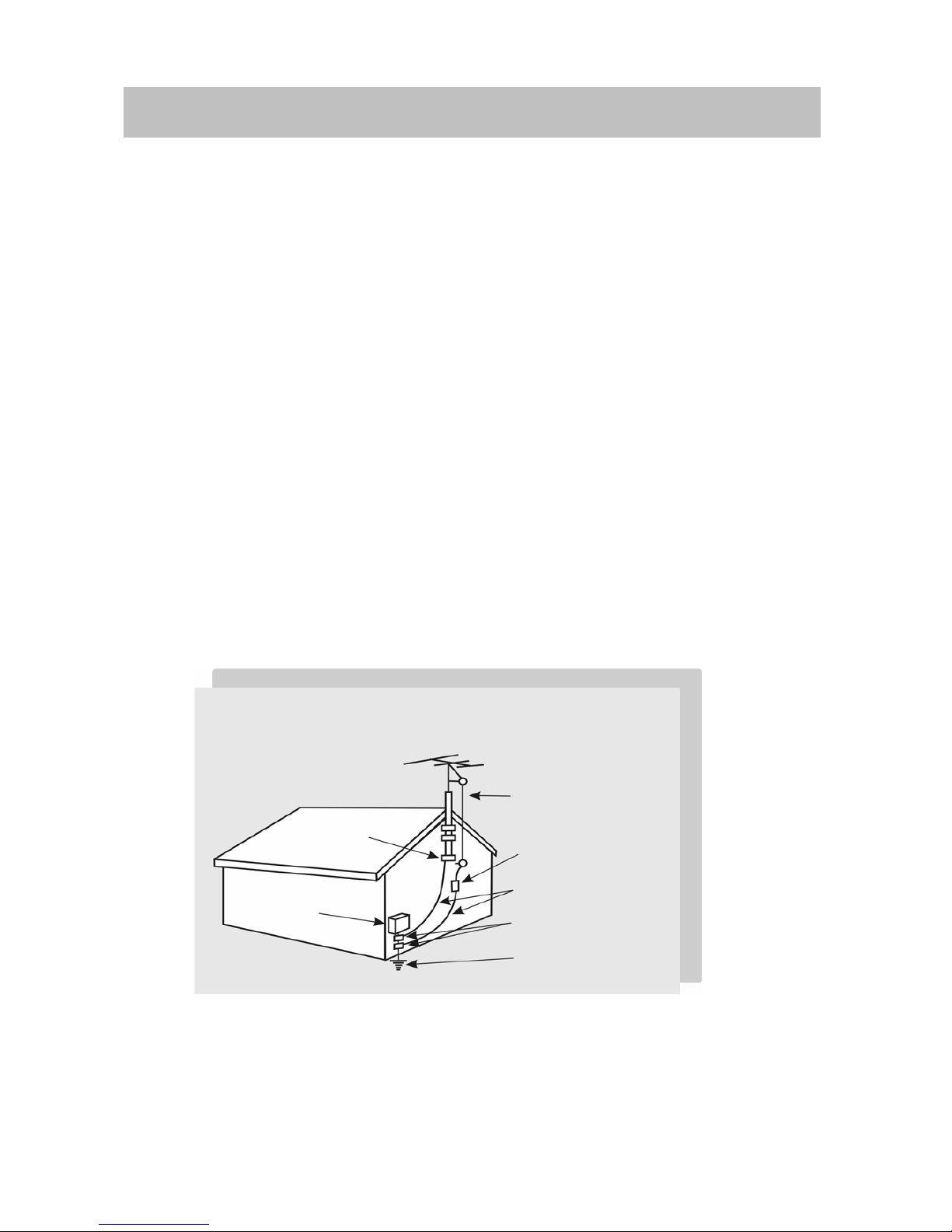
Example of antenna grounding
As per national electrical code
Antenna lead in wire
Antenna discharge
unit
Grounding conductors
Ground clamps
Power service
grounding
Electrode system unit
Ground clamp
Electric service
equipment
3
Page 4

circuits as contact with them might be fatal.
6) Ventilation-The vents and other openings in the cabinet are designed for ventilation. Do not
cover or block these vents and openings since insufficient ventilation can cause overheating
and/or shorten the life of the product. Do
not place the product on a bed, sofa, rug or other similar surface, since they
can block ventilation opening. This product is not designed for built-in installation; do not place
the product in an enclosed place such as a bookcase
or rack, unless proper ventilation is provided or the manufacturer's instructions are followed.
1.2 Product Safety Notice
1) Many electrical and mechanical parts in this chassis provide special visual
safety protection. The protection afforded by them cannot necessarily be
obtained by using replacement components rated for higher voltage, wattage, etc.
2) Before replacing any of these components, read the parts list manual carefully.
The use of substitute replacement parts, which do not have the same safety characteristics, as
specified in the parts list may create shock, fire or other hazards.
1.3 Service Notes
1) When replacing parts or circuit boards, wrap the wires around terminals before soldering.
2) Keep wires away from high temperature components.
3) Keep cable and their shielding in their original position so as to reduce interference.
4
Page 5
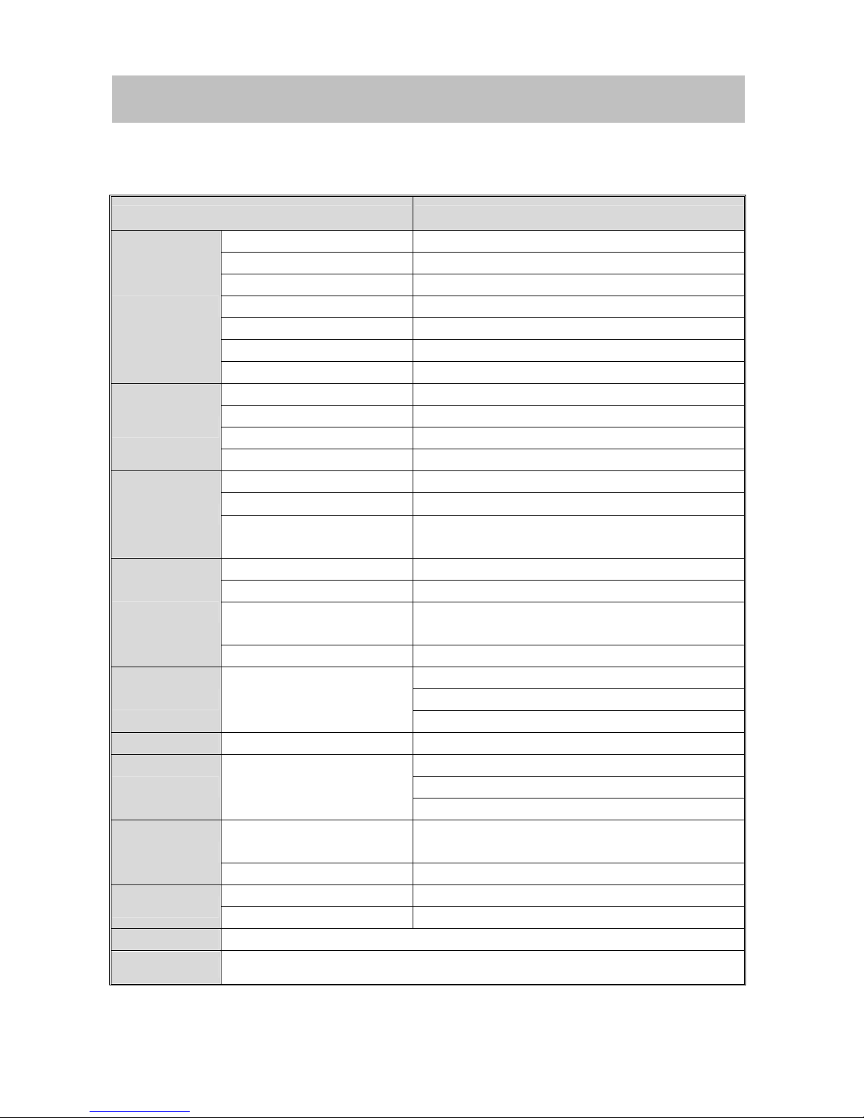
2. Specifications
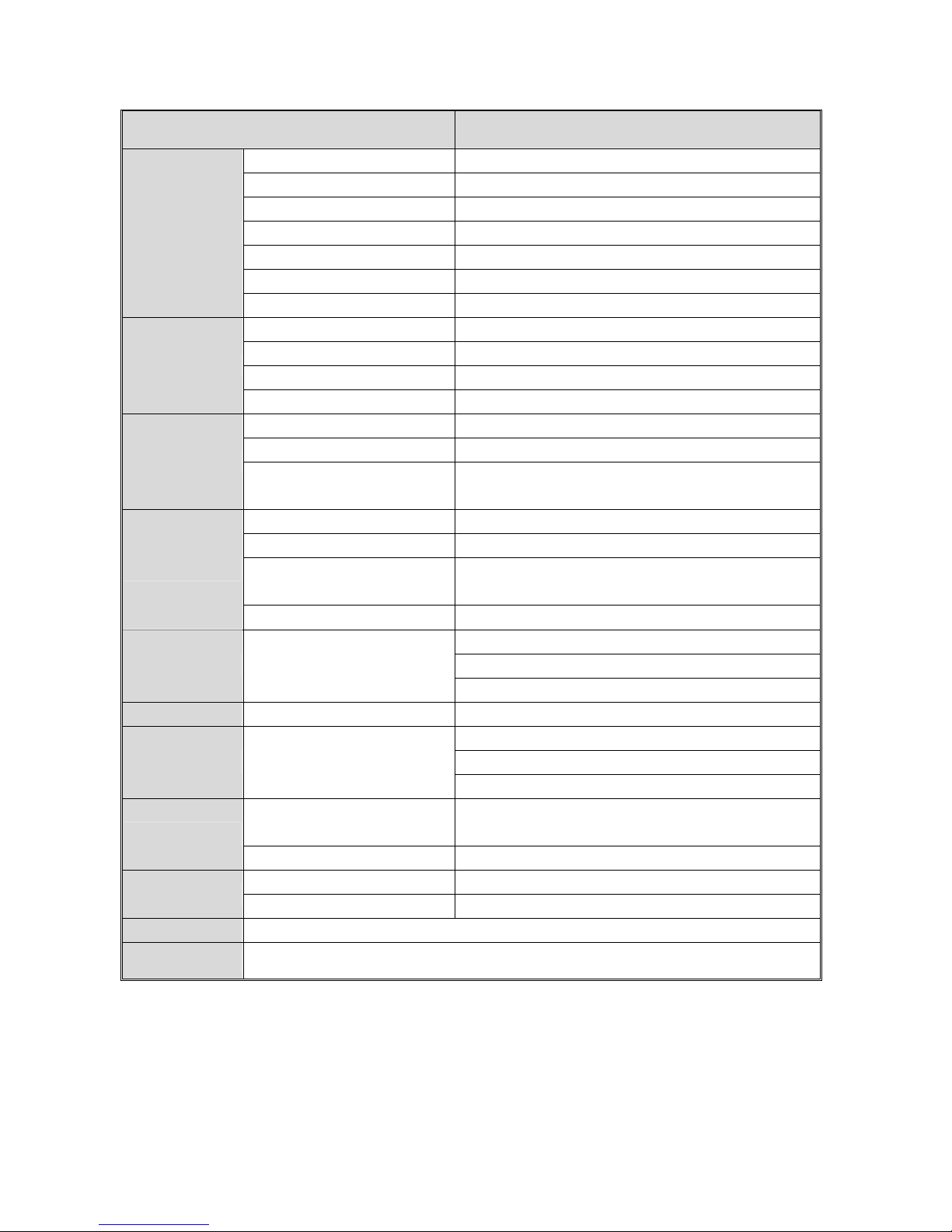
Specification
V23DXXX
ITEMS SPECIFICATION
Screen size 23” wide TFT-LCD panel
Aspect Ratio 15:9
Resolution
1280 x 768 (WXGA)
Contrast ratio 400:1(typ)
Brightness 450cd/m
2
(typ)
Viewing Angle Over 170∘(Hor.) / 170∘(Vert.)
Display
OSD Language Chinese , English, French , German , Spanish
TV standard (CCIR) NTSC
TV Turning system PLL 181 Ch.
STEREO MTS+SAP
TV I/P
CATV 125 CH.
Composite Signal CVBS
Y, C Signal S-Video
Video I/P
Composite Signal
Y, Pb Pr
HDTV system (720p, 1080i)
Signal I/P DVI-I Connector
PnP compatibility DDC / 2B
I/P Frequency
Analog:F
H
:31.5KHz to 60KHz
F
V
:56Hz to 75Hz
PC I/P
Recommended Analog:1024X768 (60Hz)
Audio 1:CVBS & S-Video
Audio 2:Y, Pb, Pr
Audio I/P Audio I/P:L/Rx3
Audio 3:PC
Video O/P Composite Signal TV only
Speaker (Build-in):5W+5W (rms)@THD<10%
3.5mm miniature stereo phone jack
Audio O/P Audio O/P:L/Px3
Sound level output::500 mV(rms)
PIP,VoV,3D De-interlace, 3D
comb-filter ,V-Chip, C.C. Settings
Yes
Other Functions
Aspect Ration Switching Normal → Periscope → Zoom →Full
Power Supply AC 110V ~ 240V, 50/60Hz
Power
Power Consumption <115W
Wight (net) 10.3Kg (Ref.) (Without Accessories)
Accessories Remote Control, Batteries, AC power cord
5
Page 6
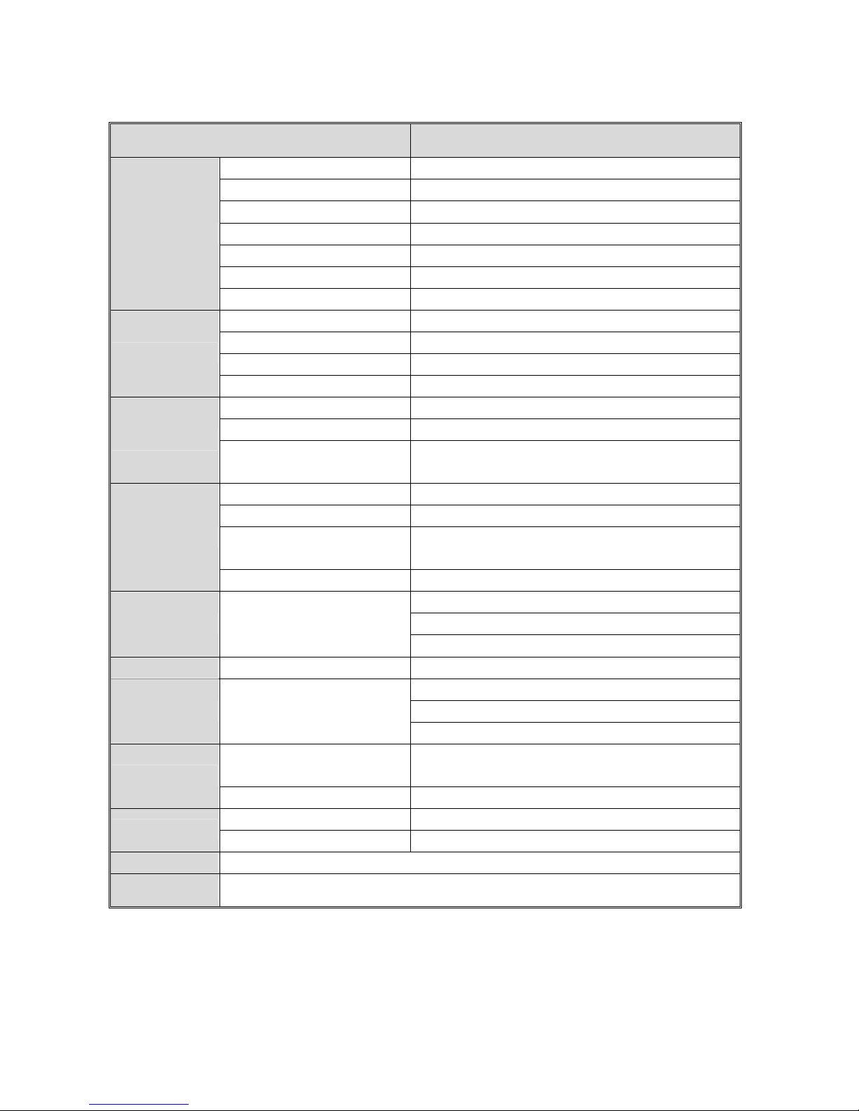
V27DXXX
ITEMS SPECIFICATION
Screen size 27"wide TFT-LCD panel
Aspect Ratio 16:9
Resolution
1280 x 720(WXGA)
Contrast ratio 600:1 (typ)
Brightness 550cd/m
2
(Typ)
Viewing Angle Over 170∘(Hor.) / 170∘(Vert.)
Display
OSD Language Chinese, English, Fre nch, German, Spanish
TV standard (CCIR) NTSC
TV Turning system PLL 181 Ch.
STEREO MTS+SAP
TV I/P
CATV 125 CH.
Composite Signal CVBS
Y, C Signal S-Video
Video I/P
Composite Signal
Y, Pb Pr
HDTV system (720p, 1080i)
Signal I/P DVI-I Connector
PnP compatibility DDC / 2B
I/P Frequency
Analog:F
H
:31.5KHz to 60KHz
F
V
:56Hz to 75Hz
PC I/P
Recommended Analog:1024X768 (60Hz)
Audio 1:CVBS & S-Video
Audio 2:Y, Pb/Cb, Pr/Cr
Audio I/P Audio I/P:L/R x 3
Audio 3:PC
Video O/P Composite Signal TV only
Speaker (Build-in):10W+10W (rms)
3.5mm miniature stereo phone jack
Audio O/P Audio O/P:L/P x 3
Sound level output::500 mV(rms)
PIP,VOV,3D De-interlace, 3D
comb-filter ,V-Chip, C.C. Settings
Yes
Other Functions
Aspect Ration Switching Normal → Periscope → Zoom →Full
Power Supply AC 110V ~ 240V, 50/60Hz
Power
Power Consumption <140W
Wight (net) 14.5Kg (Ref.) (Without Accessories)
Accessories Remote Control, Batteries, AC power cord
6
Page 7
V30DXXX
ITEMS SPECIFICATION
Screen size 29.6"wide TFT-LCD panel
Aspect Ratio 15:9
Resolution
1280 x 768 (WXGA)
Contrast ratio 600:1(typ)
Brightness 550cd/m2 (Typ)
Viewing Angle Over 170∘(Hor.) / 170∘(Vert.)
Display
OSD Language Chinese , English, French , German , Spanish
TV standard (CCIR) NTSC
TV Turning system PLL 181 Ch.
STEREO MTS+SAP
TV I/P
CATV 125 CH.
Composite Signal CVBS
Y, C Signal S-Video
Video I/P
Composite Signal
Y, Pb, Pr
HDTV Ready (720p, 1080i)
Signal I/P DVI-I Connector
PnP compatibility DDC / 2B
I/P Frequency
Analog:F
H
:31.5KHz to 60KHz
F
V
:56Hz to 75Hz
PC I/P
Recommended Analog:1024X768 (60Hz)
Audio 1:CVBS & S-Video
Audio 2:Y, Pb/Cb, Pr/Cr
Audio I/P Audio I/P:L/Rx3
Audio 3:PC
Video O/P Composite Signal TV only
Speaker (Build-in):10W+10W (rms)
3.5mm miniature stereo phone jack
Audio O/P Audio O/P:L/Px3
Sound level output: 500 mV(rms)
PIP,VoV,3D De-interlace, 3D
comb-filter ,V-Chip, C.C. Settings
Yes
Other Functions
Aspect Ration Switching Normal → Periscope → Zoom →Full
Power Supply AC 110V ~ 240V, 50/60Hz
Power
Power Consumption <150W
Wight (net) 15.2Kg (Ref.) (Without Accessories)
Accessories Remote Control, Batteries, AC cord, AC power cord
7
Page 8
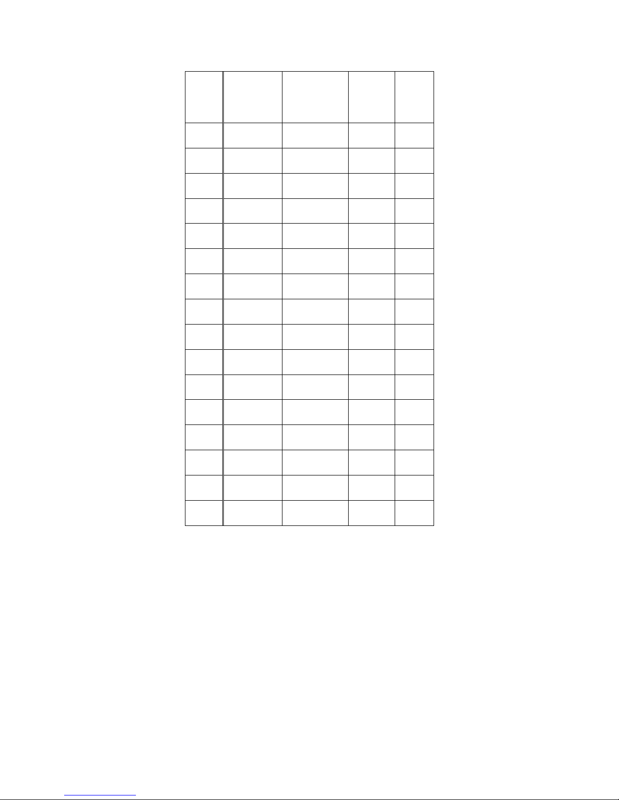
PC I/P
Mode
No.
Mode Name
Resolution
H.Freq.(KHZ)
V.Freq.(HZ)
H. Polarity
V. Polarity
Pixel
CLK
(MHZ)
1 VGA 70HZ
640*350
31.469
70.087
+
-
25.175
2 VGA 60HZ
640*480
31.469
59.941
-
-
25.175
3 VGA 72HZ
640*480
37.861
72.81
-
-
31.5
4 VGA 75HZ
640*480
37.5
75.0
-
-
31.5
5 SVGA 60HZ
800*600
35.16
56.25
+
+
36.0
6 SVGA 60HZ
800*600
37.879
60.317
+
+
40.0
7 SVGA 72HZ
800*600
48.077
72.188
+
+
50.0
8 SVGA 75HZ
800*600
46.875
75.0
+
+
49.5
9 XGA 60HZ
1024*768
48.363
60.004
-
-
65.0
10 XGA 70HZ
1024*768
56.476
70.069
-
-
75.0
11 XGA 75HZ
1024*768
60.023
75.029
+
+
78.75
12 MAC VGA
640*480
35.0
66.667
-
-
30.24
13 MAC VGA
832*624
49.725
74.550
-
-
57.283
14 US TEXT
720*400
31.469
70.087
-
+
28.322
15 WXGA
1280*768
47.73
60
-
-
80
16 WXGA
1280*720
45
60
+
+
74.25
8
Page 9

PC I/P
Mode
No.
Mode Name
Resolution
H.Freq.(KHZ)
V.Freq.(HZ)
H. Polarity
V. Polarity
Pixel
CLK
(MHZ)
1 VGA 70HZ
640*350
31.469
70.087
+
-
25.175
2 VGA 60HZ
640*480
31.469
59.941
-
-
25.175
3 VGA 72HZ
640*480
37.861
72.81
-
-
31.5
4 VGA 75HZ
640*480
37.5
75.0
-
-
31.5
5 SVGA 60HZ
800*600
35.16
56.25
+
+
36.0
6 SVGA 60HZ
800*600
37.879
60.317
+
+
40.0
7 SVGA 72HZ
800*600
48.077
72.188
+
+
50.0
8 SVGA 75HZ
800*600
46.875
75.0
+
+
49.5
9 XGA 60HZ
1024*768
48.363
60.004
-
-
65.0
10 XGA 70HZ
1024*768
56.476
70.069
-
-
75.0
11 XGA 75HZ
1024*768
60.023
75.029
+
+
78.75
12 MAC VGA
640*480
35.0
66.667
-
-
30.24
13 MAC VGA
832*624
49.725
74.550
-
-
57.283
14 US TEXT
720*400
31.469
70.087
-
+
28.322
15 WXGA
1280*768
47.73
60
-
-
80
16 WXGA
1280*720
45
60
+
+
74.25
8
Page 10
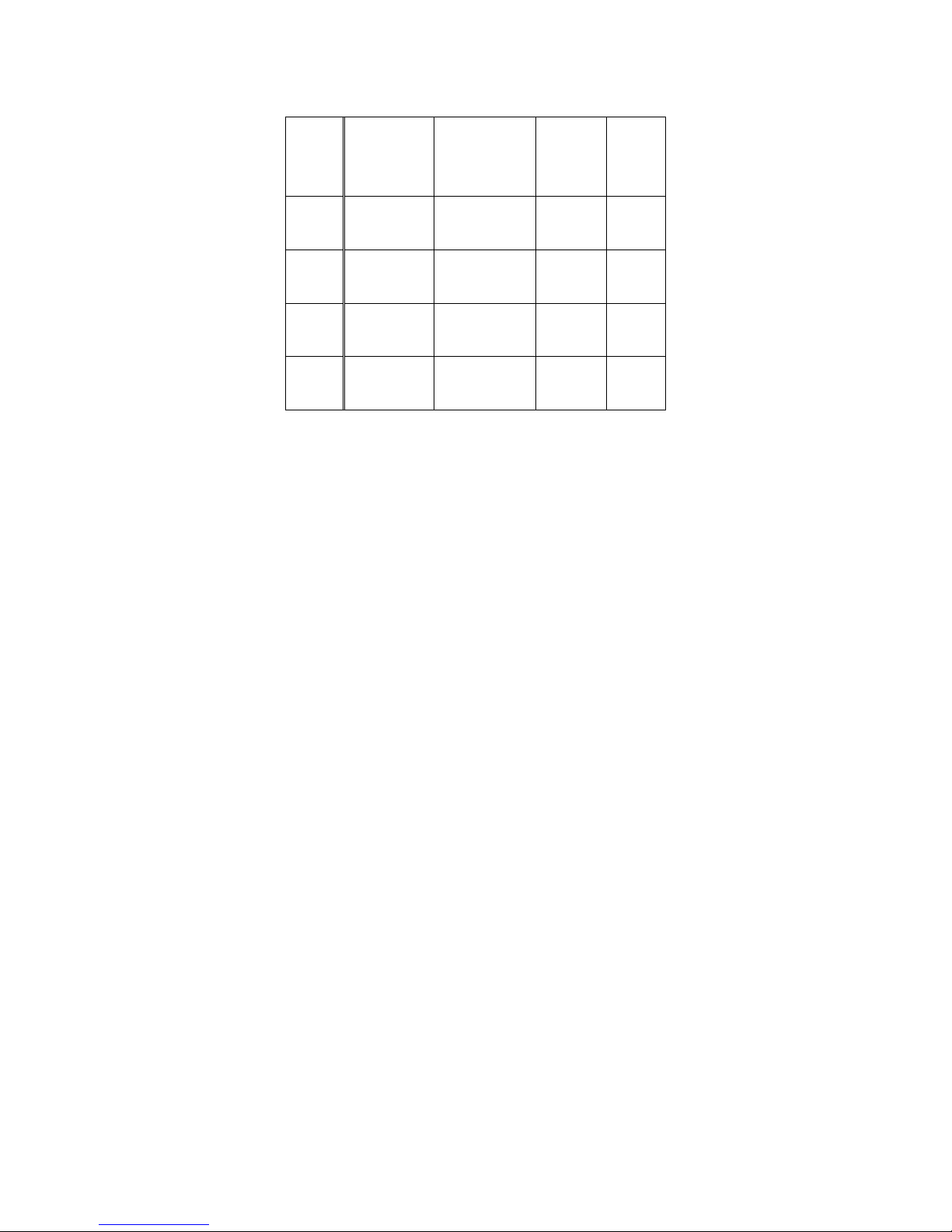
DVI I/P
Mode
No.
Mode Name
Resolution
H.Freq.(KHZ)
V.Freq.(HZ)
H. Polarity
V. Polarity
Pixel
CLK
(MHZ)
1
VGA 60HZ
640*480
31.469
59.941
-
-
25.175
DVI
2
SVGA 60HZ
800*600
37.879
60.317
+
+
40.0
DVI
3
XGA 60HZ
1024*768
48.363
60.004
-
-
65.0
DVI
4
US TEXT
720*400
31.47
70.08
+
+
28.320
DVI
9
Page 11
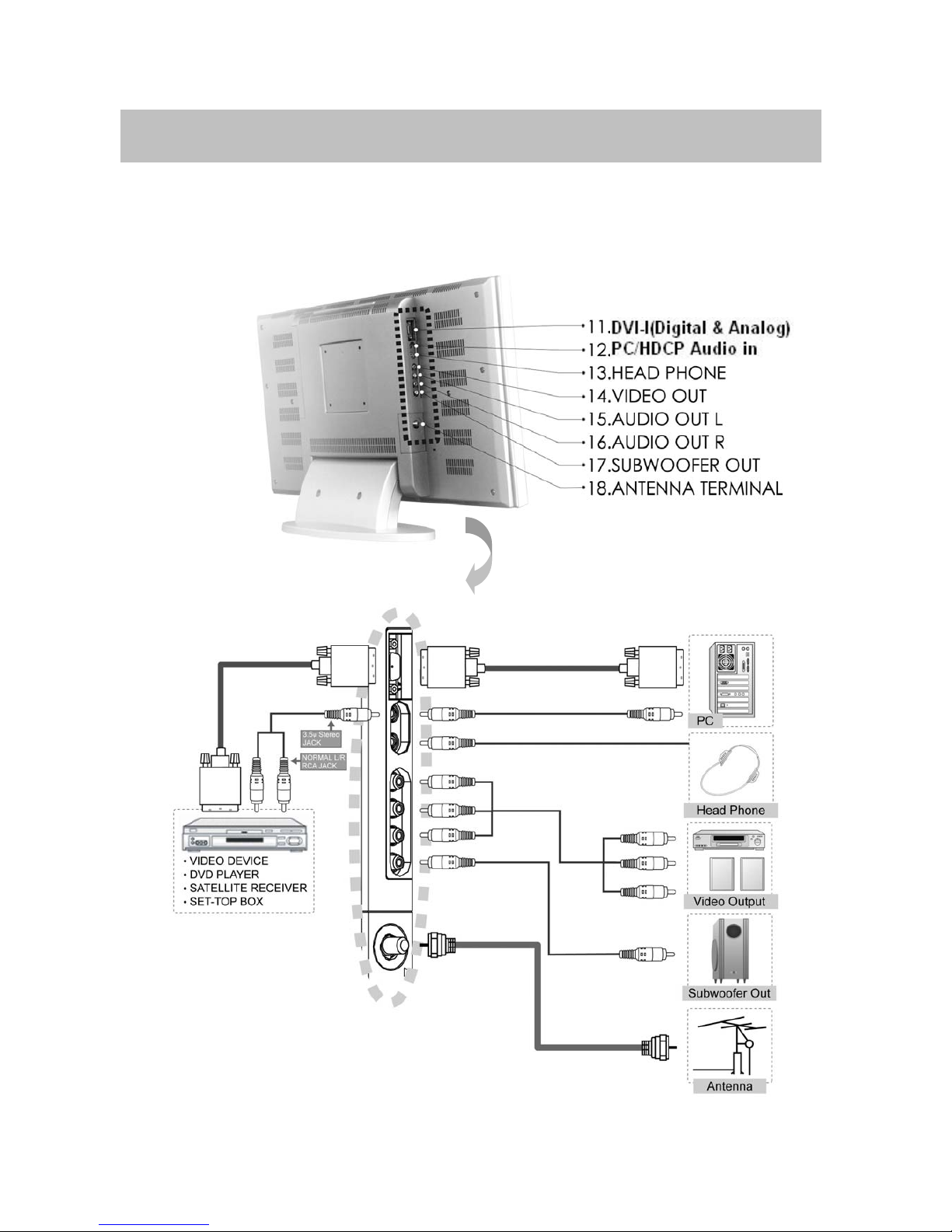
3. Connection & Applications
(TV only)
10
Page 12
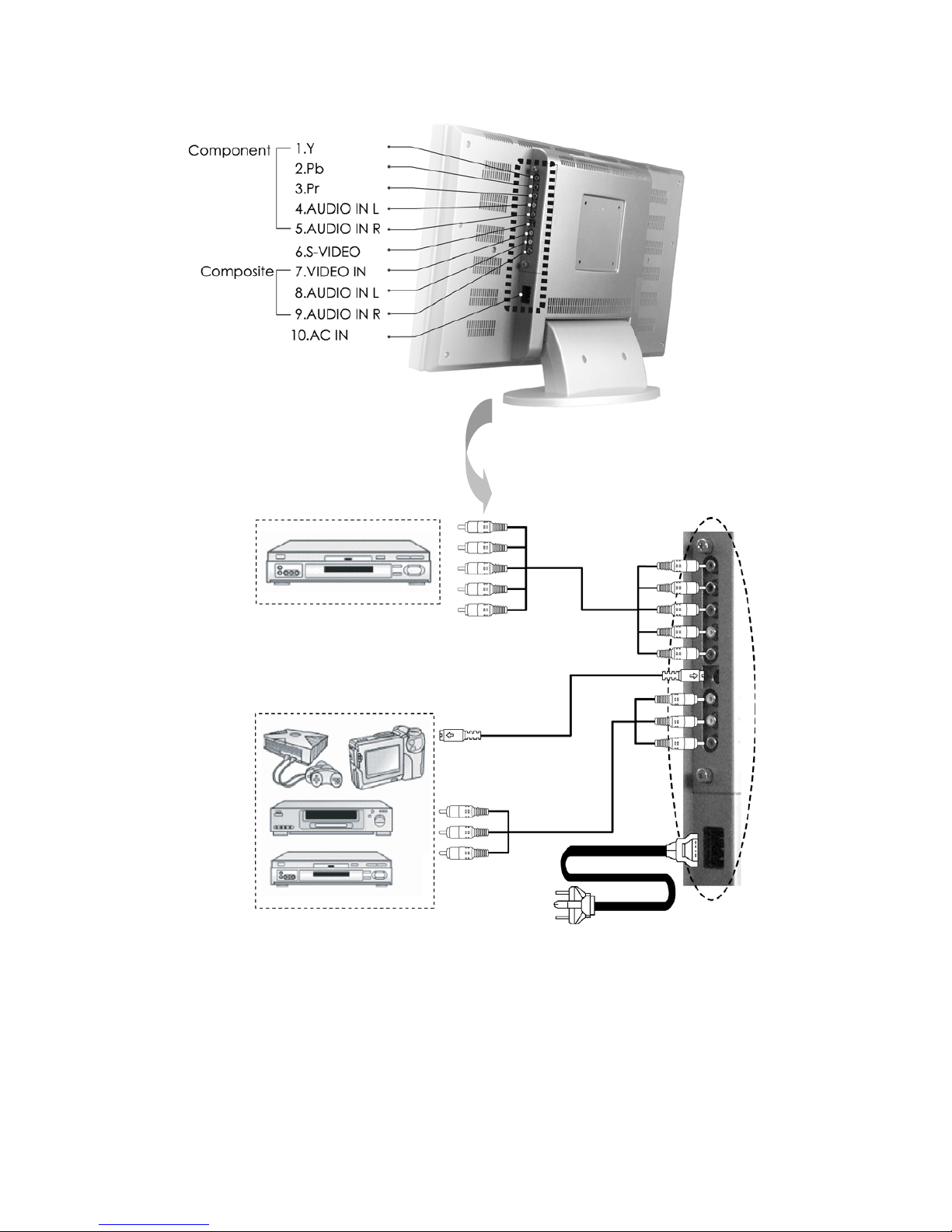
Note:
z Audio out: The level of Audio O/P is constant. It won’t be affected by aligning volume, treble and bass.
This connecter should be connected to outer audio amplifier to enlarge the volume.
z Video O/P: When user wants to connect Audio and Vide o O/ P of o ur LC D-TV to VCR for recording
program, the O/P has only one choice that is TV mode.
z Audio O/P: IF the main display is TV, the Audio O/P must be TV sound; otherwise, if sub display is TV, the
Audio I/P must be selected to “Sub”, so that the Audio O/P will be TV sound.
Video Input device
˙DVD player
˙Satellite receiver
˙Set top box
˙VIDEO Inputdevice
˙Digital Camera
˙Satellite receive
˙Set top box
11
Page 13
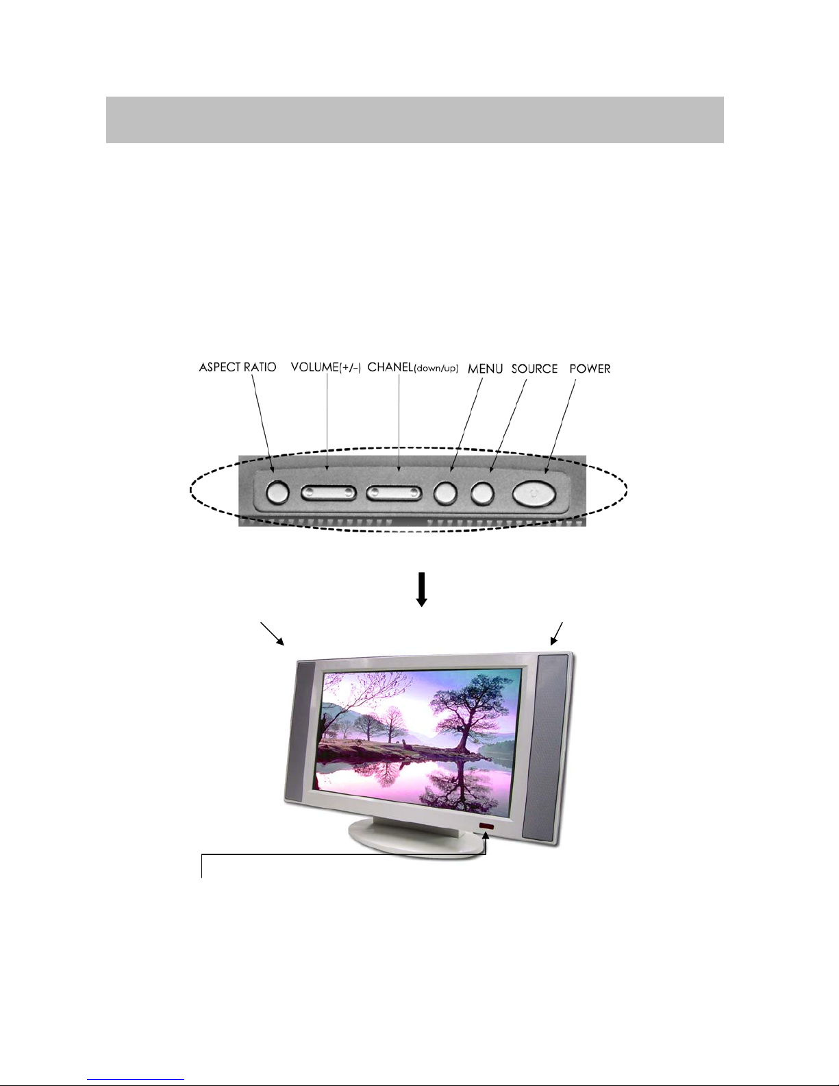
4. Control Location
These buttons control your TV’s basic features, include the on-screen mean. To use the more
advanced features, you must the remote control.
POWER: turn on or turn off the LCD TV.
SOURCE: set up the input source (PC,VIDEO,SV,TV,CV).
MENU: display the main menu.
CHANEL (down/up): change channels on sequence.
VOLUME(+/-): turn up or turn down the volume.
ASPECT RATIO: set up the display (Normal, Periscope, Zoom or Full).
Remote sensor window
Aim the remote control towards this region on the TV.
Speaker Speaker
12
Page 14
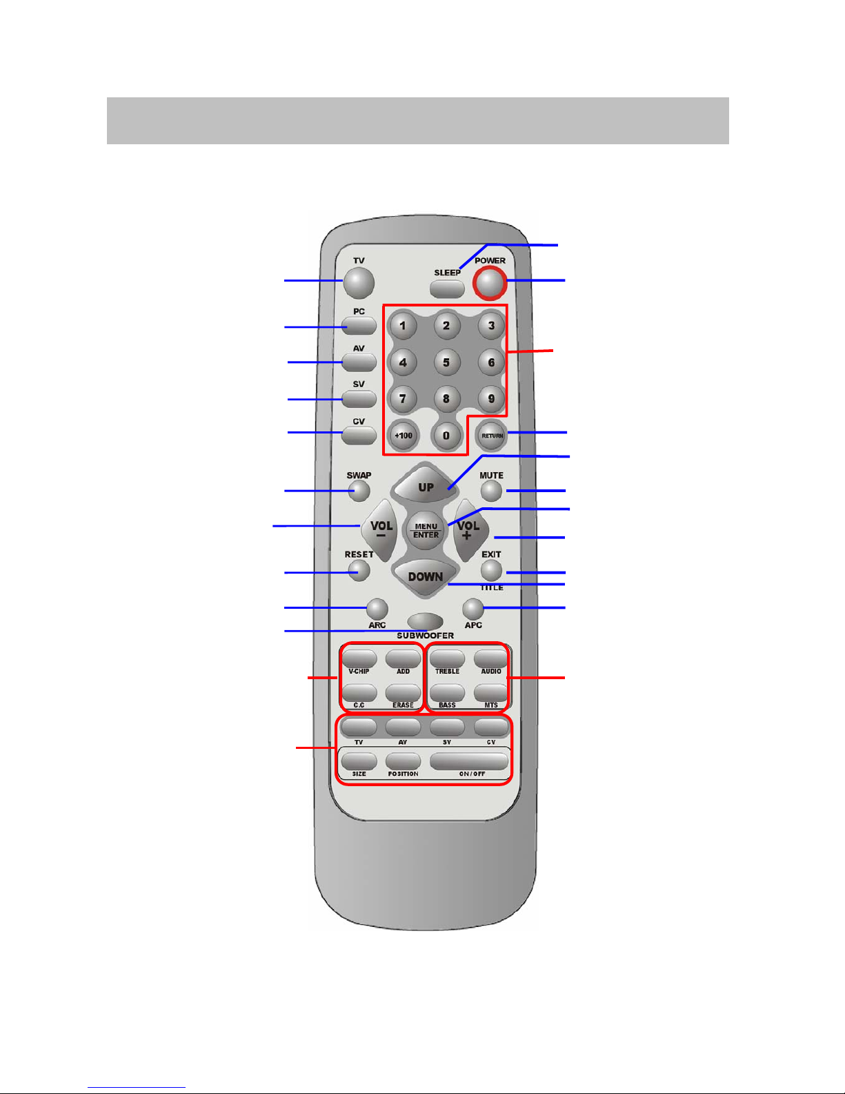
5. Remote Control
The remote control pad works almost as same as ordinary TV remote control that includes the basic
function needed while viewing a live video:
Sleep
Power
Number Buttons
Return
Channel UP
Mute
MENU/Enter
VOL+
TITLE / EXIT
Channel DOWN
APC
Audio Function
TV
PC
AV
SV
CV
SWAP
VOL-
Reset
ARC
Subwoofer
Other Function
PIP Function
13
Page 15
Summary of Control Button
PPoowweerr ccoonnttrrooll
Press POWER button Direct to turn on or turn off the display
Selecting the signal source
Press TV button Direct to switch to the TV mode.
Press AV button Direct to switch to the AV Video mode.
Press SV button Direct to S-Video mode.
Press CV button Direct to switch to the Component mode (Y Pb Pr).
Press PC button Direct to switch to the PC mode.
Menu Setting
Press MENU/ENTER button Display the main on-screen menu or enter the next menu.
Press TITLE/EXIT button Display the current channel digits/Exit from the menu.
Changing Channels
Press UP button Press Up to change channel on the TV.
Press DOWN button Press Down to change channel on the TV.
Press 0~9,+100 button To select channels directly on the TV.
Press RETURN button Return to the previous channel on the TV.
Sound Control
Press VOL+ button Press to turn up the volume.
Press VOL- button Press to turn down the volume.
Press MUTE button Press to temporarily cut off the sound.
Press MTS button Press to choose stereo, mono or separate audio program supply the
multi-channel sound services.
Press AUDIO button Select present audio is main display or sub display.
Press TREBLE button Adjust the treble of audio.
Press BASS button
Press SUBWOOFER button.
Adjust the bass of audio.
Open the subwoofer function.
PIP Control
Press ON/OFF button Press to watch one of video sources on sub display. Press again to make the
sub display disappear.
Press TV、AV、SV、CV button Press to select one of the PIP window input source.
Press SIZE button To make the PIP window double, large or small.
Press POSITION button Press to move the PIP window to:Top Left→Top Rig ht→Bottom Right→
Bottom Left→Repeat
Other Function
Press SWAP button Change main display and sub display.
Press RESET button Return to the original factory settings.
Press ARC button In PC source:Set the picture window to full or normal.
In Video source:Set the picture window to normal→full→periscope→zoom.
Press APC button Select Normal, Clear, Dark, and Theater mode for picture control.
Press SLEEP button Press to select a present time interval for shut off.
Press V-CHIP button Set Parent Control function.
Press C.C button Set the caption of TV programs show on or off.
Press ADD button Add the channel of TV programs in TV source.
Press ERASE button Erase the channel of TV programs in TV source.
14
Page 16
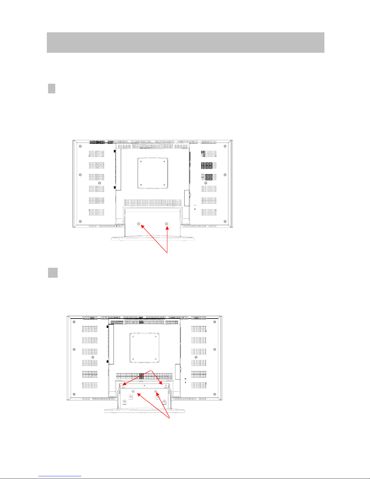
6. Disassembly Instructions
A. Face down the LCD-TV :
Face down the LCD-TV on a smooth plane with a soft material to protect the panel faceplate.
B.Base Neck Removal Procedure :
1. Remove 2 screws from Neck Cover. (Indicated as “ A “)
Then you could take the Back Cover of neck apart from the LCD-TV
C. Base Removal Procedure:
1. Remove 4 screws from the Back Cover. (Indicated as “ B ” and “ C ”)
Then you could take Base (assembly) apart from the LCD-TV.
A
B
C
15
Page 17
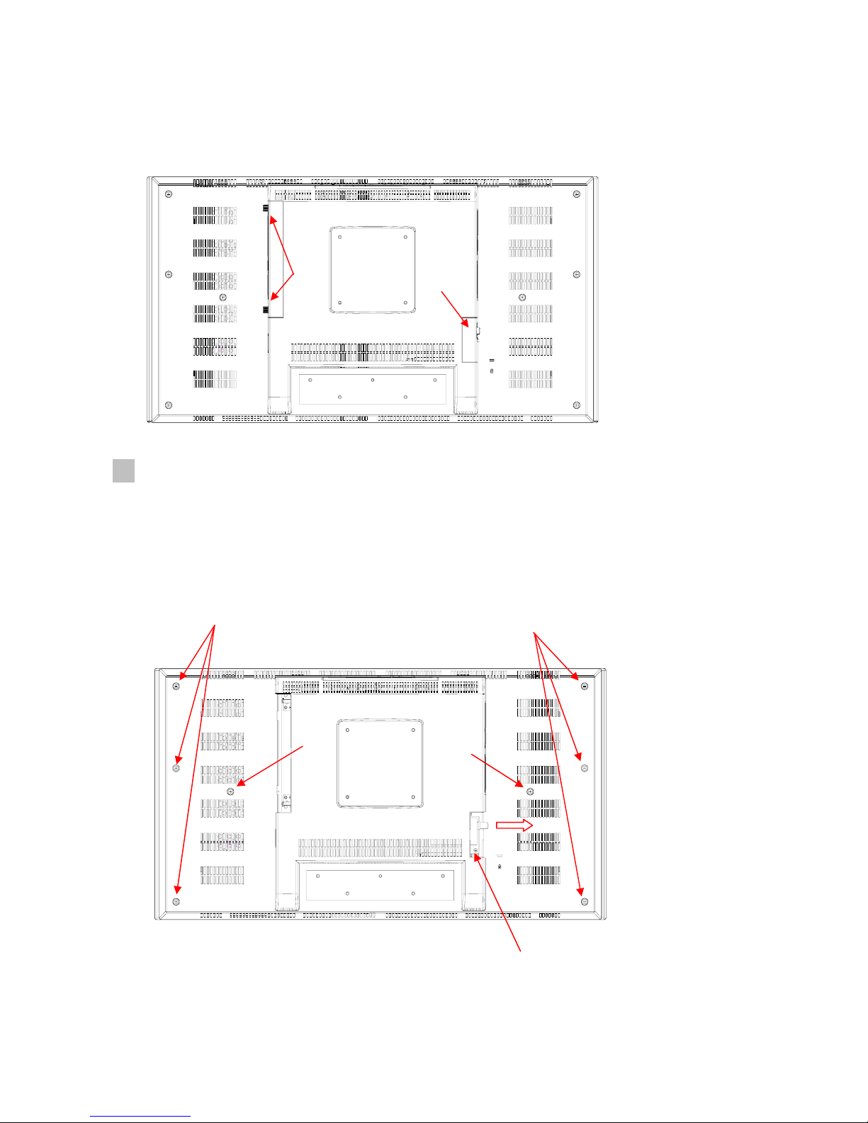
D. Tuner Cover & AV Cover Removal Procedure:
1. Remove Tuner Cover. (Indicated as “D”)
2. Remove AV Cover before, you should be loose the screw (Indicated as “E”)
E. Back Cover Removal Procedure:
1. Remove 8 screws from the Back Cover. ( Indicated as “ F “and “ G “ )
2. Remove a screw from the Tuner Board. (Indicated as “ I ”)
3. Take slide of tuner board.
Then you could take Back Cover apart from the LCD-TV.
F
G
G
F
E
D
I
16
Page 18
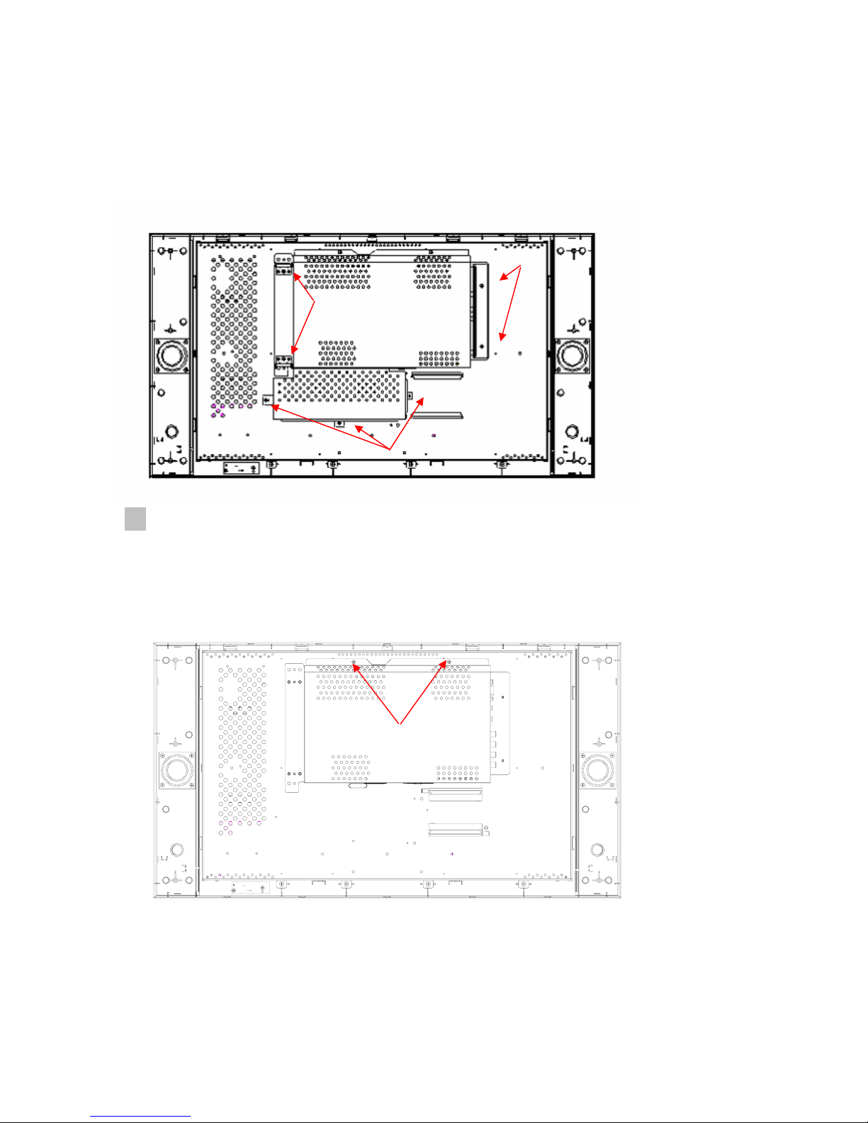
F. Right/Left Side Covers and Tuner Board Removal Procedure:
6.1 Remove 4 screws from Slide of AV PCB & left side Covers. (Indicated as “ H ”)
6.2 Remove a screw from the Tuner Board. (Indicated as “ I ”)
6.3 Remove 3 screws from the power case assembly. (Indicated as “ J ”)
Then you could take Slide of AV PCB, Power case, and Left Side Covers Removal.
G. Main PCB Shield Removal :
1. Remove 2 screws from Main PCB Shield. (Indicated as “ K”)
Then you could take Main PCB Shield apart from Main Bracket and the PCB Board will
be shown on it .
K
H
H
J
17
Page 19
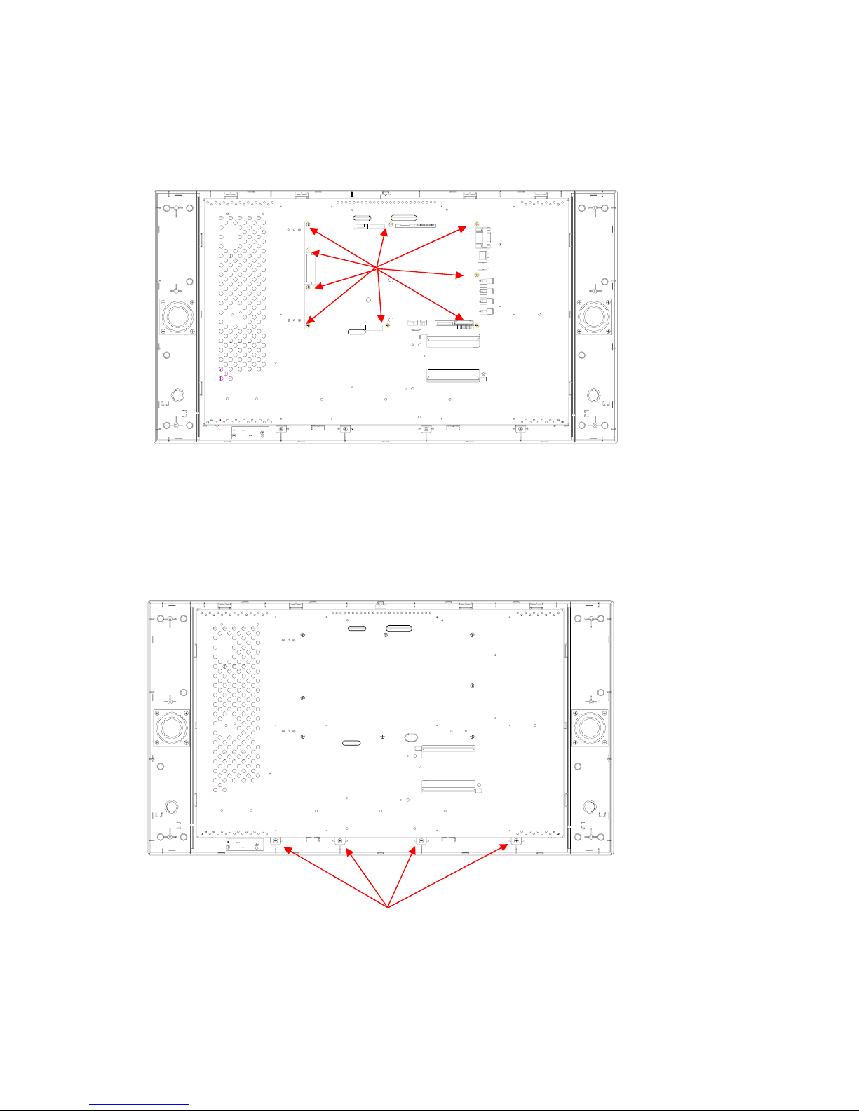
H. Main PCB Removal procedure:
1. Remove 9 screws from the Main PCB. (indicated “ L “)
Then you could take Main PCB apart from the LCD-TV .
I. Panel Bracket Removal procedure:
1. Remove 4 screws from the Panel Bracket. (Indicated as “ M ”)
Then you could take Panel Bracket apart from the Front Cover.
L
M
18
Page 20
19
Page 21
UT01
I044
I010
I033
I024
I035
I018
I006
I031
I001
I038
I037
I032
I019
I020
I009
I013
I012
I035
I040
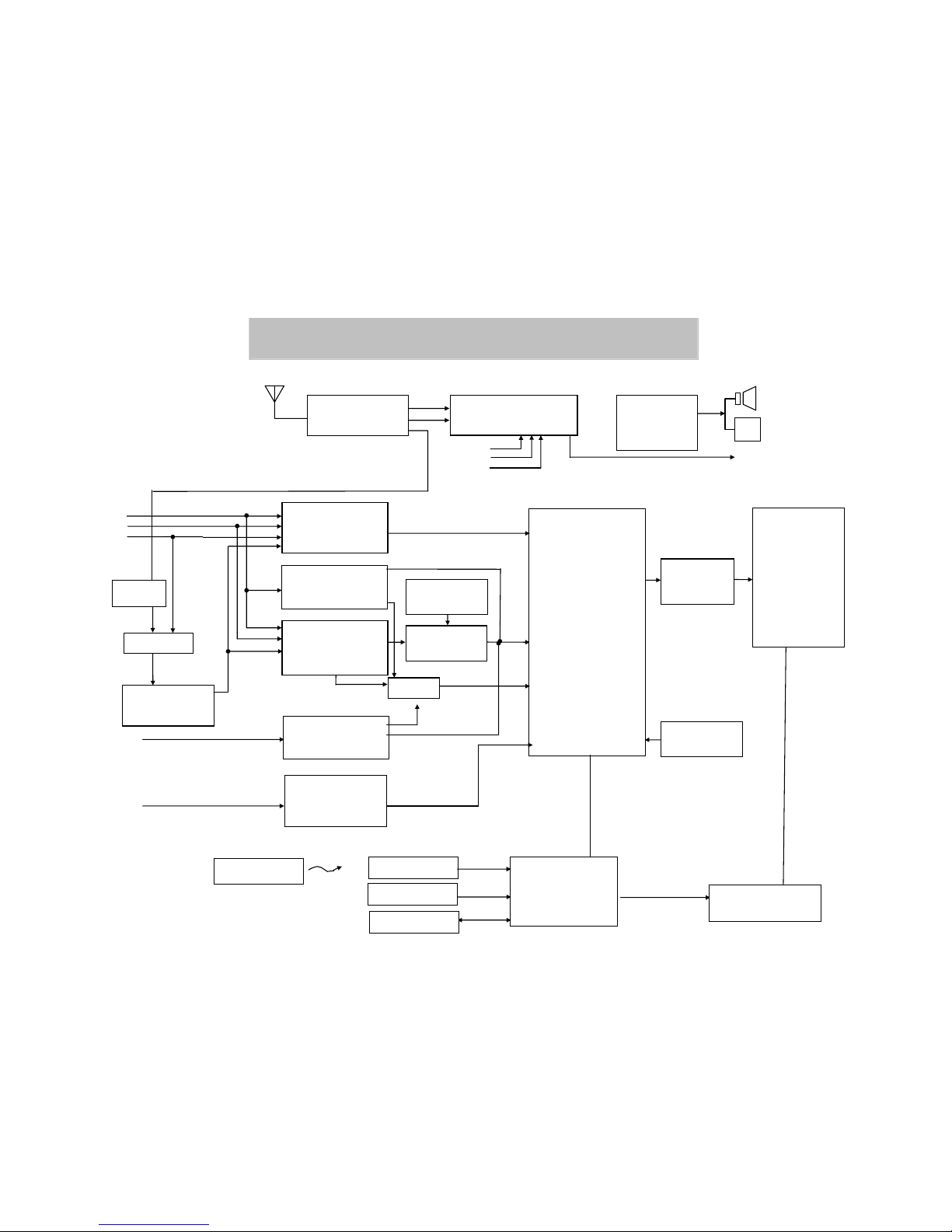
7. Block Diagram
Video Decoder
SAA7117
De-Interlace
SiI504C
ADC
Scaler
TP6761
LCD
Panel
23”/27”/30”
ADC
AD9883A
Video Decoder
SAA7117
Micro Controller
TP2808)
Key Pad
INVERTER
E2PROM
IR Pad
Remote Control
8 bi
t
CV
SV
Interlaced
Pro
g
ressive
24 bit
AV
3D Comb filter
TC90A65F
(or UPD64083)
V-Chip
Z8612912
Port V(Sub)
Port B(Main)
Port A(Main)
PI5V330
10W + 10W
Speaker
Headphone
Subwoofer
TV – Tuner
(Philips)
FQ1236 MK3
4:1
MTS & Audio Processor
MSP3440G
Audio Amp.
TFA9843)
CV Audio
SV/A V Audio
PC Audio
ANT
Audio
P15V330
TV/AV
Interlaced
Sync.
VGA
I
2
C
SIF
Video
PC
RAM
HY57V64
RAM
HY57V16
Interface
THC63
LVDM83A
Silicon Image
Sil169
DVI
20
Page 22

8. Troubleshooting
8.1 Symptom Codes :
CODE SYMPTOM COUNTERMEASURES
NP1
No Picture and No Sound
in TV mode.
z Make sure the Power cord and Antenna cable are
properly connected .
z Make sure the batteries in remote control are not
flat.
z Switch to TV source by pressing TV button.
z Select the correct signal source: “ANT” or “STD/
HRC/ IRC ” in OSD menu.
z Run “Auto Scan ” in OSD menu.
NP2
No Picture and No Sound
in video mode.
z Check the connection between the optional video
equipment and the TV.
z Press AV, SV, or CV button on the remote control to
select the corresponding video source.
NP3
TV is automatically turned
off.
z Check if the “SLEEP” timer is activated .
z Press POWER button to turn on the TV once again.
NP4
Screen appears “totally
snowy” in TV mode. After
10 min., it turns off
automatically.
z Check if Aerial cable is correctly connected.
z Press POWER button to turn on the TV again.
z Press CH Up/Down buttons to change channels.
No picture and and no Sound
NP5
Screen appears “No
Signal” in video mode.
After 10 min., it turns off
automatically.
z Check if Video Cable is correctly connected and
Video Device is normal.
z Press POWER button to turn on the TV again.
z Press AV, SV, or CV button on the remote control to
select the corresponding video source.
PP1
Double Images / Ghosts If the TV suffers interference from signals reflecting from
mountains or buildings , double-pictures or Ghosts will
occur.
z Adjust the Antenna’s location and direction
z Replace it with one with better directionality .
z Turn off or disconnect the booster if it is in use , as
the booster may be inappropriate.
PP2
Snowy picture and noisy
Sound
If snow totally blocks out the picture , there may be a
problem with the Antenna or Antenna Cable .
z Have the TV and Antenna been connected
properly ? Has the Antenna cable been damaged ?
z Is the Antenna pointing in the right direction ?
z Is the Antenna itself faulty ?
z Try using a booster , as signal transmission may be
low.
PP3
Distorted picture and
noisy sound
z Turn off or disconnected the booster if it is in use ,
as broadcast signals may be too strong.
Poor Picture
PP4
Dotted Lines / Stripes
in the picture.
If the TV or Antenna suffers interference from other
equipment , stripes or noise may appear in the picture.
z Keep the TV away from noise sources such as
personal computer , amplifier , cars, motorcycles or
hair-dryers.
z If the aerial suffers interference from a radio tower
or high-voltage wire , contact the local dealer.
21
Page 23

CODE SYMPTOM COUNTERMEASURES
PP5
Stripe noise. z Check the coaxial cable connected with the TV is not
oxidized
z Do not use 300 ohm twin lead cables as interference
may occur
z It is recommended to use a 75 ohm coaxial cable
(not supplied) to get premium quality picture.
z Keep the aerial cable away from other connecting
cables.
PP6
No color, too light or too
dark
z Adjust the picture settings —
APC, Brightness,
Contrast, Saturation , Color Temp.
z Press RESET button on remote control to return all
settings to factory settings.
Poor Picture
PP7
Poor picture on particular
channel.
z Use “Fine Tune” in OSD to manually adjust a
particular channel for optimal reception.
NS1
Good picture, no sound z Mak e sure the headphone is not connected. (option)
z Check audio connections between Equipment &
LCD-TV.
z Press MUTE or VOL Up to cancel the muting.
No Sound or Noisy Sound
NS2 Noisy noise z Make sure that the antenna connected is 75 ohm
coaxial cable (not supplied) , not 300 ohm twin lead
cables .
z Keep the antenna cable away from other connecting
cables.
z Press MTS button to select “Mono” which will
reduce the noise.
z Adjust BASS or TREBLE properly on remote
control.
PC1 PC display is Not Full
Screen
z Select “Auto Image” in OSD menu to optimize the
image .
z If executing Auto Image Adjust still can not achieve
full screen display, adjust “V. Position” and “H.
Position” in PC mode
PC2 Horizontal Noise or Color
pattern is not uniform
z Select “Auto Image” in OSD menu to optimize the
image .
z If still no good , adjust “Phase” in OSD menu
PC3 “Out of Range” message z Maximum PC resolution supported is 1280x768
, so the screen will appear “Out of range” at higher
resolution.
z Reduce the resolution to1280x768 from the PC.
Note
20〞panel resolution is 640 x 480.
PC4 No Sound z Make sure PC audio Input is well connected.
PC
PC5 After “No Signal ” has
appeared on PC mode for
a while, the view
disappears and the LED
Indicator turns from
Green to”Amber” .
z Press any key on keyboard or move the mouse to
activate the PC , because the PC may go to power
saving status.
z Check if the D-sub or DVI connector (Cable) is
disconnected or loose.
22
Page 24

CODE SYMPTOM COUNTERMEASURES
RC1 Remote Control does not
work
z Make sure the batteries in remote control are not flat
z Check the polarity of the batteries
z Use the remote control in the front of the TV or from
less than seven meters away.
z make sure the Remote Sensor Window is not under
strong lighting.
Remote Control
RC2 Can not change channels
with the remote control
z Press TV button to switch to TV mode.
PH1
Picture suddenly Stops
Responding or
abnormal.
z Press RESET button on remote control .
z Unplug and then plug the Power Cord of the TV from
the AC outlet.
Picture Halt / Abnorm al
NG1
Issues can’t be solved. z If the picture still abnormal, execute “ Clear
EEPROM”.
STEPS
:
1. Press POWER key to turn off the LCD-TV.
2. Press CH key▽ , then press Power key of remote
control to turn on the LCD-TV, after
3 seconds, then release CH▽ key.
3. When「INITIAL EEPROM」appears on the screen,
on the INTTAL EEPROM is complete.
Note : Remind user that every setting will return to
factory preset mode including PIN of parental
control (PIN :1234), channel setting.
Note
1. CV and PC including D-sub or DVI modes, are not available on Sub-display of PIP .
2. If main display is CV , PIP mode is not available.
23
Page 25

8.2 Troubleshooting Flow Chart
3~5V
Is the Voltage at
I029#8= 5V?
No
No
Replace I029
Yes
No
No picture
No picture
Erase
EEPROM
Picture
appears
Replace I012(MCU)
Fix at
factory
No picture
Yes
Restart and check
sources are
connected
Re-plug white connector,
then measure voltage
again
Check if inverter is
connected correctly.
Yes
N
o
Panel wire (P005) is
connected correctly?
Re-
plug
No
否
否
Yes
Yes
Yes
Does the LED
light up?
Is LED display
Amber?
Restart signal to
ensure H. V.
sync are not
absent
End
Is it entering into
power saving on PC
mode?
No
Picture
appears
Picture
appears
Replace Main Board
PWB-0812
No
No
No
Yes
Re-
plug
No picture
No picture
No picture
No picture
Re-
plug
No
Yes Yes
Picture
appears
No
Yes
No picture
No picture
Picture
appear
No picture
Replace Inverter,
test again.
Measure white connectors
of 2 sides pin voltage that
are at 3V and 24V
White connector of
power Module (8p
or 12p) is connected
correctly?
Check if panel
light works?
Re-
plug
No picture Appear
Measure of
I029#4 =? volt
0~0.5V
Picture
appears
Picture
appears
Picture
appears
Picture
appears
Replace Power
Module, test
again.
Erase
EEPROM
Picture
appears
(1)Power Start NG
24
Page 26

(2) Picture abnormal
No
Replace V901
(LCD panel)
Yes
No
End
Yes
Yes
Yes
No
Change Inverter
and check picture
No
No
No
Yes
Yes
Yes
No
Yes
Change main
board (PWB-0812),
and check picture.
Change Power
Module, and check
picture
No
After welding,
then check the
picture.
Are the panel
cables (P005)
attached
correctly?
Re-plug the
panel cable, and
check the
picture
Erase
EEPROM, and
then check the
picture is
否
Check side SMD of
I019&I020 is welded
correctly?
The Ver. Or Hor.
Sync. does not
hold
in any source
25
Page 27

Steps to clean EEPROM
1. Press POWER key to turn off the LCD-TV.
2. Press CH key▽ , then press Power key of
remote control to turn on the LCD-TV, after
3 seconds, then release CH▽ key.
3. When「INITIAL EEPROM」appears on the
screen, on the INTTAL EEPROM is complete.
Trouble Shooting
1. MCU platform using Topro TP2808
2. Label:V30DMBT-U21
3. Check Sum:3E86H
BIOS Version:V30DMBT-U21 WBK-MP 1.1 12/21/04
EEPROM INITIAL:Power + Channel Down
4. Enter Factory Mode:Power + Menu Key
5. Leave Factory Mode:Power off
6. Self – Test Mode (for Burn in):Push Menu + Channel Up + Power ON、Key at same time, and
then loose Power On Key first、Keep push Menu and Channel Up Keys for 2 seconds,test pattern
will appear on the screen(Self-Test Mode can’t be disable by disconnecting Power Supply, it must
thru. Power Key).
7. Disable Self-Test Mode:Push Power Off/On Key
WBK
V30D-U21
MP 1.1
´Custom
´Model NO.
´Edition
26
Page 28

9. Electronic Circuit Description
9.1 Main Board Circuit
(1) DVI-I signal
Refer to circuit diagram of PWB-0812
The analog RGB video input signals are supplied through the DVI-I cable which is
terminated at P022. These three input signals are approximately 0.7Vpp in amplitude.
R374、R301 and R327 give resistance of 75Ω respectively for impedance matching. These
R、G、B video signals are ac coupled via 0.047U capacitor C021、C016 、C013 and then
fed into the I001 AD converter (MST9883C) at Pin54、49 and 43 respectively. These analog
R、G、B video signals are converted to the their digital forms in I001. The outputs of digital
data including 8 bits red、8 bits green、8b bits blue signals are assigned at Pin70 ~ 77、Pin
2 ~ 9 and Pin 12 ~ 19 of I001,and applied to Port A of I019 (Scaler:TP6761 ) Hsync &
Vsync are applied to I001 (MST9883C) #30 & #31 and the processed signal taken from #66
& #64 are fed into I019 (TP6761) #18、#19..
CLK signal is taken from I001 (MST9883C) #67 and applied to I019 (TP6761) #156.The
LCD-TV is designed to have the DDC/2B FUNCTIONS. Communication between the
LCD-TV and computer for DDC is via P022 (DVI-I connector ) #20、#21 which are defined
as SCL、SDA signals. The computer will read out the EDID from the I011 (EEPROM) and
the EDID data is written into the EEPROM in the factory during production.
The digital input signal through DVI-I cable which is terminated at P022. Input signal from
TMDS low voltage differential signal input data pairs Pin 80、81、85、86、90、91 and TMDS
signal input clock pairs 93、94 are fed into I040 (SiI 169).
The I040 (SiI 169) supports High-bandwidth Digital Content Protection (HDCP) by
decrypting the pixel data stream received from an HDCP transmitter in the video host
system. HDCP provides a secure method of delivering high-definition content between a
host (such as a set-top box, DVD player, or D-VHS player) and display (such as an HDTV,
projector, or A/V receiver).
The SiI 169 comes pre-programmed with a production set of HDCP keys in its internal
EEPROM. In this way the keys are provided the highest level of protection as required by
the HDCP specification.
27
Page 29

UT01
I044
I010
I019
I033
I024
I035
I018
I006
I031
I001
I038
I03
I032
I020
I009
(2) AV Signal
Refer to the page 8 in circuit diagram of PWB-0812.
V30DXXX / V27DXXX can process 4 different Video signals,including Composite
Video (CVBS)、Separate Video (S-Video ) and Component Video (YUV). Component
Video also includes two types Y Cb/Cr and Y Pb/Pr, and I018,I031 SAA7117 is 16
channels analog input. There are 4 A/D in it’s I/O port, So it can match this model.
Examples for different of input source signals are listed one by one as follow. (please
refer to the circuit diagram):
A. TV:
i. TV signals enter from ANT to Pin#1 of UT01 FQ1236 MK3 Tuner. Pin
#14 output Audio MPX signal, while Pin#12 output TV (CVBS) Video signal.
ii. Audio MPX signal does MTS demodulation from I044 (I044 MSP3440G).
It can output Audio signal including Mono、 Stereo、Sap and so on. Then
through I010 (Audio Power Amp) to Speaker.
iii. After the Video signal to the V-Chip circuit (I025 NJM2244、I033
Z86129、I030 74HC126) to modulate it, output to I031 SAA7117 Video
Decoder (Main) or I018 SAA7117 Video Decoder (Sub) circuit to do
modulation and Video source exchanges for CVBS signal type. Then CVBS
signal changes to the ITU-656 type by I031 or I018 and outputs to I019 Scaler
to process. 8 Bit belongs to Data parts, and H sync, V sync, CLK directly
connect to Pin#162、163、164 of Scaler. Then R、G、B signal respectively output
six bits to panel.
10W +
10W
Speaker
Headphone
TV – Tuner
(Philips)
FQ1236 MK3
4:1
MTS & Audio
Processor
MSP3440G
Audio Amp.
TFA9843)
CV Audio
SV/A V Audio
PC Audio
ANT
Audio
SIF
Video
Vide o Deco der
SAA7117
De-Interlace
SiI504C
ADC
AD9883A
Scaler
TP6761
LCD
ADC
AD9883A
Vide o Deco der
SAA7117
8 bit
CV
SV
AV
Interlaced
Progressive
24 bit
24 bit
3D Comb filter
TC90A65F
(
or UPD 64083
)
V
-Chip
Z8612912
Port
V(Sub)
Port
B(Main)
PI5V330
P15V3
TV/AV
Interlaced
Sync.
VGA
PC / Component Video
RAM HY57V64
RAM
HY57V16
Interface
THC63
28
Page 30

B. CV (Y Pb Pr ):
Entering from P50 signal, then enters Pin#43、48、54 of AD9883 passed by the
matching impedance resister and capacitance. It converts to RGB signal of
YUV by I006 and passes to Port B of I019 by six row-resister RP08 ~ RP12.
Then output to panel.
C. Audio:
The rest of Audio source all connect Audio Processor ( I044:MSP3440 ) to
each left and right voice channels. Controlled by MCU (I012) and selected
through I044, just output one source to Audio Power Amp (I010: TFA9843) to
Speaker.
(3) MCU
Microcontroller
Refer to circuit diagrams Sheet 5 of 11.
The microcontroller I012 Topro TP2808 is running with the clock based on 14.318
MHz by X003.
C127 and R096 constitute a reset circuit. It properly the necessary active high reset
signal for I012 (Microcontroller) to operator properly. This reset signal is result that is
fed into I012 (Pin#10) to provide the necessary system reset for the proper operation
of I012.
The signal IR- DAT (Pin#15 of I012) is used for Infrared Receiver. If the IR Received
some signal,I012 will send interrupt signal by Pin #2、3 (MSDA、MSCL) to control
any chip.
The signal designated AD0 ~ AD7 (Pin36 ~ 43 of I012) are data signal used for
transferring data between I012 and I019.
The signal TXD and RXD ( Pin#13、11 of I012 ) are used for debugging during
firmware.
I013 (24LC16B) provides necessary non-volatile storage for system operating
variables and parameters. It is controlled by I012 via MSDA and MSCL signal, witch
pulled-up to +5V voltage with R092 and R093 (10KΩ).
(4) Panel interface
Refer to circuit diagrams Sheet 6 of PWB-0812
The signals of panel interface are all from I019 to the LCD Panel.
The signal FPVCC (Pin#96 of I019) and MMTB3904 (Q003) control the +5V power
to the LCD Panel.
The signals FPBACK and DVD0 (Pin#95、62 of I019 ) are used for the control of
backlight’s On / Off state and Panel luminance.
The signals SHFCLK、PDE、PVYSNC、PHSYC come from Pin#90 ~ 94 of I019, and
then fed into P005. These four signals are used for panel image display controls.
29
Page 31

Pin#A1BLU0 ~ 7、A1GRN0 ~ 7、A1RED0 ~ 7 and B1BLU0 ~ 7、B1GRN0 ~ 7、
B1RED0 ~7 are data output from I019 to P005 and P802( to LCD Panel ). They are
buffered by LP02,LP04,LP06,LP08,LP10,LP12 and filtered associated capacitors.
These outputs are organized into even and odd connectors, each with 18 bits.
9.2 Keyboard Circuit & IR Lens board
The keyboard and IR lens circuit are shown in chapter 10-3 of the circuit
diagrams.
9.3 Inverter Circuit
The inverter board is fed with +24V through P802#1~#5 on Power module and offers
4.1ma (typical ) to each lamp of backlight in LCD panel.
The brightness adjusted in OSD menu is to control the voltage at P802#11 while this
voltage is offered by I019 (Scaler:TP6761)#62.
The range of the voltage is from 0V to 3.3V. If the voltage of P802#11 is 0V, the
screen will get light; if it’s 3.3V, the screen will get dim. It means that the dif ferent
voltage will change the lamp current through the inverter to make the screen lighter or
dimmer.
9.4 Power Module
The Power Module circuit shown in chapter 10-6. The Power Module provide +5V
+24V though P802 for whole system.
30
Page 32

10. Circuit Diagram
PCB Main Board Circuit
31
Page 33

32
Page 34

33
Page 35

34
Page 36

35
Page 37

36
Page 38

37
Page 39

38
Page 40

39
Page 41

40
Page 42

41
Page 43

42
Page 44

43
Page 45

44
Page 46

45
Page 47

46
Page 48

47
Page 49

48
Page 50

49
Page 51

11. PCB Layout
50
Page 52

51
Page 53

52
Page 54

53
Page 55

54
Page 56

55
Page 57

56
Page 58

57
Page 59

58
Page 60

59
Page 61

POWER Layout
60
Page 62

61
Page 63

62
Page 64

63
Page 65

64
Page 66

12. Electrical Part List
Model
part number
V23DXXX V27DXXX V30DXXX
NOTE
TFT Panel
LG
LC230W015051253665
(include
Inverter)
CMO V270W1
1.5051253656
(include
Inverter)
CMO V296W1
1.5051253668
(include
Inverter)
Inverter
panel is
included
panel is
included
panel is
included
Power
Module
6693006615(RA)
6693006611(RB)
1.HOAU242001
150W
6693006610(RA)
2.PHIHONG
150W
6693006601(RB)
6693006610(RA)
6693006601(RB)
Tuner
Board
PWB-0707
U12-5097632521
PWB-0707
U05-5097632508
U12-5097632519
U21-5097632519
PWB-0707
U05-5097632509
U21-5097632523
I/O Board
PWB-0612
U12-5097624527
PWB-0612
U05-5097624513
U12-5097624523
U21-5097624523
PWB-0612
U05-5097624514
U21-5097624530
IR Board
PWB-0739-2
U12-5098800942
PWB-0739-2
U05-5098800801
U12-5098800908
U21-5098800908
PWB-0739-2
U05-5098800803
U21-5098800969
Key Board
PWB-0739-1
U12-5098800941
PWB-0739-1
U05-5098800800
U12-5098800907
U21-5098800907
PWB-0739-1
U05-5098800802
U21-5098800968
EE
PARTS
Main
Board
PWB-0812
U12-5097641403
PWB-0812
U05-5097641400
U12-5097641402
U21-5097641402
PWB-0812
U05-5097641401
U21-5097641405
65
Page 67

Speaker
U12-5055123800 U05-5055126200
U12-5055126200
U05-5055125600
U21-5055123700
Remote
control
U05-5052731052
U12-5052731043
U21-5000100072
U05-5052731052
U21-5000100072
MCU
6647021817 6647021817 6647021817
Note:
Different
model have
different
firmware
version.
Signal
Cable
DVI-I cable
U05-5057424010
U21-5057424010
DVI-I cable
U05-5057424010
U21-5057424010
Power
Cord
U12-5056705900 U05-E056705900
U12-5056705900
U21-5056705900
U05-E056705900
U21-5056705900
User's
Manual
U12-5030007049 U05-5030057109
U12-5030057126
U05-5030057109
U21-5030057146
Front
Cover
U12-5641101101 U05-5641101601
U12-5641101003
U21-5641101002
U05-5641101401
U21-5642298207
Back
Cover
U12-5642294312 U05-5642292206
U12-5642292209
U21-5642292210
U05-5642292010
U21-5642292018
ME
PARTS
Base
U12-5641416405 U05-5640410000
U12-5641412707
U21-5641416305
U05-5640410000
U21-5641412707
66
Page 68

13. Mechanical Disassembly
67
 Loading...