

Page 1

REPAIR MANUAL
ProPalette 8K Series
Color Film Recorders
Includes models 8035, 8045, 8067
May 24, 2000
© Copyright Polaroid Corporation, 2000. All rights reserved.
“Polaroid” and “ProPalette” are trademarks of Polaroid Corporation, Cambridge, MA, U.S.A.
All other product names may be trademarks of their respective owners.
Americas Business Center
Technical Services
201 Burlington Road
Bedford MA 01730
TEL: 1.781.386.5309
FAX: 1.781.386.5988
Page 2

Polaroid 8K Series ProPalette Film Recorders
Repair Manual
Contents
Introduction...............................................................................................9
Purpose of This Manual.......................................................................... 9
Manual Organization.............................................................................. 9
Other Service Documents.....................................................................10
Important Safety Instructions ............................................................... 10
Electrostatic Discharge Warning.......................................................... 10
Note, Caution and Warning Conventions............................................. 10
1 8K Series ProPalette Description ......................................................11
Model 8035 Description....................................................................... 11
Model 8045 Description....................................................................... 12
Model 8067 Description....................................................................... 13
8K Series ProPalette Factory Optimization.......................................... 13
Film Recorder Optics............................................................................ 13
Electronics ............................................................................................14
System Status LCD Panel..................................................................... 14
Ports......................................................................................................15
Software and Interface Accessory Kits................................................. 15
Palette for Windows Kit ....................................................................16
RasterPlus for Macintosh Kit............................................................. 16
Palette for Macintosh Kit................................................................... 16
Accessory Kit PID Numbers ............................................................. 17
8K Series ProPalette Feature Summary................................................ 18
System Specifications........................................................................... 20
2 Hardware Operating Information ....................................................22
Installation Quickstart........................................................................... 22
Unpack the Box .................................................................................22
Position the Film Recorder................................................................22
Connect the Film Recorder................................................................ 23
Connection Tips.................................................................................26
Install the Software............................................................................26
Configure RasterPlus for Macintosh ................................................. 27
Configure RasterPlus for Windows...................................................27
2
Page 3

8K Series ProPalette Repair Manual Contents
2 Hardware Operating Information (continued)
Terminating the ProPalette Internally................................................... 28
Changing the ProPalette SCSI ID......................................................... 29
Controls, Indicators and Connectors.....................................................30
Front (Without Camera) .................................................................... 30
Keypad............................................................................................... 31
Using the 35mm Camera Back.............................................................31
35mm Camera Back Description....................................................... 31
Loading 35 mm Film......................................................................... 32
Using the 4x5 Camera Back .................................................................33
Loading 4x5 Film .............................................................................. 34
Using the 6x7 Camera Back .................................................................35
Loading 6x7 Film .............................................................................. 35
Locking the Film Type Via the Keypad ...............................................40
Locking the Camera Type via the Keypad ...........................................41
Bulk Camera Support ........................................................................... 41
Leaving a Film Leader.......................................................................... 41
Making Exposures................................................................................ 42
Removing Exposed Film ......................................................................43
Rewinding a Partially Exposed Roll.....................................................43
Advancing Film.................................................................................... 43
Removing and Replacing the 35mm Camera Back.............................. 43
Enhanced Information Display............................................................. 44
Artifact Warning Indicators.................................................................. 44
Hardware Configuration Display.......................................................... 45
High Density Grids............................................................................... 45
Protecting the CRT and Camera from Dust.......................................... 45
Cleaning the CRT Face......................................................................... 45
Cleaning the Camera Lens.................................................................... 46
Testing the Hardware Installation......................................................... 46
Troubleshooting Hardware and Film Problems.................................... 47
Color Balance and Exposure for Negative Film................................ 47
Running a Self-Test........................................................................... 48
Redisplaying an Error Message.........................................................48
LCD Panel Messages............................................................................ 48
Setup Menu Reference.......................................................................... 50
Activating Monitor Mode.....................................................................51
Activating Monitor Mode Via Front Panel Buttons.......................... 51
Activating Monitor Mode Via Digital Board ....................................51
Activating Monitor Mode Via LCD Menu........................................ 52
3
Page 4

8K Series ProPalette Repair Manual Contents
2 Hardware Operating Information (continued)
Displaying or Changing the Stored Serial Number.............................. 52
Viewing the Stored Serial Number and Board Versions................... 52
Serial Number Syntax........................................................................ 53
Changing the Stored Serial Number..................................................54
Viewing and Interpreting the Error Log...............................................54
Enabling and Disabling the Watchdog Timer.......................................54
3 Theory of Operation...........................................................................55
Design Objectives................................................................................. 55
Image Quality Objectives .................................................................. 55
Manufacturability and Serviceability.................................................55
CPU....................................................................................................56
Deflection and Geometry Control ..................................................... 56
Sharpness Control.............................................................................. 56
Exposure Control...............................................................................56
ProPalette Major Systems.....................................................................57
Exposure System .................................................................................. 59
Exposure Sequence............................................................................ 59
Exposure System Components.......................................................... 59
Power Supply.....................................................................................60
Digital Board ........................................................................................ 62
Digital Board Circuits........................................................................62
Digital Board Components................................................................ 62
Digital Board Functional Groups....................................................... 64
Group 1 Functions .............................................................................65
Group 2 Functions .............................................................................65
Group 3 Functions .............................................................................65
Group 4 Functions .............................................................................66
Analog Board ........................................................................................ 67
Slowscan Description and Imaging Sequence...................................... 68
Grid for Deflection ............................................................................ 69
Video DAC Data Generation............................................................. 69
Exposure Summary............................................................................ 70
Flash Description..................................................................................70
Flash Data Organization.................................................................... 70
Programs for Reading and Writing the Flash .................................... 71
Autoluma Process................................................................................. 72
Firmware Description........................................................................... 73
Downloading New Firmware.............................................................73
General Description...........................................................................73
Camera Back Interface ......................................................................... 73
4
Page 5

8K Series ProPalette Repair Manual Contents
3 Theory of Operation (continued)
Keypad/LCD Interface.......................................................................... 75
LCD Menus ....................................................................................... 76
Exiting from Menus........................................................................... 76
Startup Messages............................................................................... 76
Status Messages.................................................................................76
Film Tables........................................................................................77
Pacing Commands................................................................................ 77
4 Troubleshooting and Diagnostics......................................................78
Recommended Diagnostic Sequence.................................................... 78
Utility Program Summary.....................................................................78
Connecting to the Service FTP Site......................................................78
Inspection and Cleaning ....................................................................... 79
Firmware Upgrade................................................................................79
Purpose .............................................................................................. 79
Obtaining the Latest Firmware.......................................................... 79
Required Tools and Equipment ......................................................... 80
Upgrade Procedure with Parallel Cable.............................................81
Upgrade Procedure with SCSI Cable.................................................81
ProPalette Startup Diagnostics and Tests............................................. 83
Test Image Exposure Sequence............................................................85
Monitor Mode....................................................................................... 85
Error Message Redisplay...................................................................... 85
Serial Communication Cable................................................................ 86
Purpose .............................................................................................. 86
Required Equipment.......................................................................... 86
Wiring Diagram.................................................................................86
Digital Board Diagnostics (FPDIAG) via Host Computer...................86
Purpose .............................................................................................. 86
Required Tools and Equipment ......................................................... 87
Test Procedure ................................................................................... 87
PCPLUS Configuration........................................................................ 88
Uploading and Running a Hex File...................................................... 89
Purpose .............................................................................................. 89
Required Tools and Equipment ......................................................... 89
Procedure........................................................................................... 89
Digital Board Interface Test .................................................................93
Purpose .............................................................................................. 93
Required Tools and Equipment ......................................................... 93
Test Procedure ................................................................................... 93
5
Page 6

8K Series ProPalette Repair Manual Contents
4 Troubleshooting and Diagnostics (continued)
Analog Board Voltage Test .................................................................. 95
Purpose .............................................................................................. 95
Required Tools and Equipment ......................................................... 95
Test Procedure ................................................................................... 95
Analog Board Functional Test via Host Computer ..............................96
Purpose .............................................................................................. 96
Required Tools and Equipment ......................................................... 96
Test Procedure ................................................................................... 96
Analog Board Functional Test Troubleshooting ...............................98
Parallel Port Hardware Test............................................................... 98
SCSI Interface Hardware Test........................................................... 98
Image Evaluation..................................................................................98
Purpose .............................................................................................. 98
Required Tools and Equipment ......................................................... 98
Printing the Test Images.................................................................... 98
Error Logging (ERRSTAT.EXE).........................................................99
Error Classes and Messages............................................................. 100
Error Log Data................................................................................. 101
Running ERRSTAT.EXE................................................................ 102
Sample Report ................................................................................. 102
Board Versions ................................................................................103
Error Message and Symptom Tables..................................................104
LCD Panel Error Messages ............................................................. 105
Host System Error Messages...........................................................107
Host System Plug-In Symptoms...................................................... 109
Operation and Performance Symptoms...........................................111
Image Quality Symptoms................................................................ 115
Diagnostic (FPDIAG) Error Message Tables.................................. 116
5 Parts Replacement............................................................................121
Removal of the Front Bezel Assembly............................................... 122
Installation of the Front Bezel Assembly ...........................................122
Removal of the LCD Keypad Assembly ............................................123
Installation of the LCD Keypad Assembly......................................... 123
Removal of the LCD Panel................................................................. 124
Installation of the LCD Panel............................................................. 124
Removal of the Front Bezel Door....................................................... 125
Installation of the Front Bezel Door................................................... 125
Removal of the Power Switch ............................................................126
Installation of the Power Switch.........................................................126
Removal of the Camera Plate Assembly ............................................ 127
Installation of the Camera Plate Assembly......................................... 128
6
Page 7

8K Series ProPalette Repair Manual Contents
5 Parts Replacement (continued)
Removal of the Camera Connector/Cable Assembly......................... 128
Installation of the Camera Connector/Cable Assembly...................... 129
Removal of the Top Cover and Rear Panel Assembly .......................129
Installation of the Top Cover and Rear Panel Assembly....................130
Removal of the Stepper Motor ........................................................... 131
Installation of the Stepper Motor........................................................ 132
Removal of the Autoluma Board Assembly....................................... 133
Installation of the Autoluma Board Assembly ...................................134
Removal of the Wheel Position Sensor (Photo Interrupter)............... 134
Installation of the Wheel Position Sensor (Photo Interrupter)............ 136
Removal/Installation of the LCD Interface Cable..............................137
Removal/Installation of the Camera Cable Assembly........................ 137
Removal of the Electronics Drawer....................................................139
Installation of the Electronics Drawer................................................ 140
Removal of the Digital PC Board Assembly...................................... 140
Installation of the Digital PC Board Assembly ..................................141
Replacement of the Camera Power Fuse............................................ 141
Removal of the Analog PC Board ...................................................... 141
Installation of the Analog PC Board................................................... 142
Removal of the Low Voltage Power Supply...................................... 142
Installation of the Low Voltage Power Supply...................................143
Removal of the Light Box Assembly .................................................143
Installation of the Light Box Assembly..............................................146
Disassembly of the CRT..................................................................... 149
Reassembly of the CRT......................................................................149
Removal of the Front Plate Assembly................................................150
Installation of the Front Plate Assembly.............................................150
Removal of the Filter Wheel............................................................... 151
Installation of the Filter Wheel...........................................................151
Removal of the High Voltage Power Supply......................................152
Installation of the High Voltage Power Supply.................................. 152
7
Page 8

8K Series ProPalette Repair Manual Contents
6 Using the Flash Manager Utility .....................................................153
ProPalette Flash Device Description ..................................................153
Flash Manager Description................................................................. 153
Running Flash Manager...................................................................... 154
Requirements................................................................................... 154
Starting and Using Flash Manager...................................................155
Reloading Firmware ........................................................................155
Switching Between Virtual Flash Devices ......................................156
Erasing the Entire Virtual Flash ...................................................... 156
Erasing a Single Code Block........................................................... 157
FLASHMAN Menu Options ...........................................................158
FLASHMAN Common Code Blocks.............................................. 158
VFO Code Blocks............................................................................ 158
VF1 Code Blocks............................................................................. 159
7 Schematic Drawings .........................................................................160
Digital Board Schematics................................................................... 161
Analog Board Schematics...................................................................170
Autoluma Board Schematic................................................................ 178
Keypad Board Schematic ...................................................................179
Power Fail Fix Schematic................................................................... 180
Interconnection Diagram .................................................................... 181
Index.......................................................................................................182
8
Page 9

8K Series ProPalette Repair Manual Introduction
Introduction
Purpose of This Manual
This manual is intended to be a reference and training guide for authorized service
technicians who install, troubleshoot and repair the following Polaroid 8K Series
ProPalette Color Film Recorders:
• ProPalette 8035
• ProPalette 8045
• ProPalette 8067
Manual Organization
This manual is organized into seven sections:
1 ProPalette Description Describes the 8K Series ProPalette Color
Film Recorders, along with their features, components and
specifications.
2 Hardware Operating Information This section includes the setup,
operating and troubleshooting instructions provided to users in the 8K
Series ProPalette Hardware Manual (reproduced in this manual for
the convenience of service technicians).
3 Theory of Operation Detailed explanations of 8K Series ProPalette
system and component functions; for use in diagnosing problems and
performing other service.
4 Troubleshooting and Diagnostics Instructions for diagnosing image
defects, errors and other malfunctions, along with likely causes and
suggested corrective action.
5 Parts Replacement Instructions for replacing individual 8K Series
ProPalette components.
6 Using the Flash Manager Utility Description of the Flash Manager
utility program and instructions for using it to view and program 8K
Series ProPalette flash devices.
7 Schematic Drawings Major circuit board and interconnection
diagrams for use in troubleshooting.
9
Page 10

8K Series ProPalette Repair Manual Introduction
Other Service Documents
In addition to this manual, ProPalette service personnel should have access to the
following documents:
8K Series ProPalette Parts Catalog
8K Series ProPalette Hardware Manual
Palette Export Software User Guide
RasterPlus Software Manual
ProPalette Test Stand Manual (locations with appropriate equipment only)
Important Safety Instructions
When servicing a ProPalette film recorder, always take the following safety precautions:
• Read and understand all applicable service procedures before proceeding.
• Turn off and unplug the unit before servicing.
• When service procedures require the unit to be plugged in with the cover
off, take special care to avoid contact with high voltage connections, wires
and components.
Warning: The ProPalette Color Film Recorder has
hazardous internal voltages. Maintenance
operations, especially those performed with the
printer cover removed, should be performed
only by qualified service personnel.
Electrostatic Discharge Warning
ProPalette circuitry can be easily damaged by small, unnoticeable static discharges.
Always use an anti-static mat and wrist strap when removing the ProPalette cover or
when servicing the unit with the cover removed.
Note, Caution and Warning Conventions
The use of notes, cautions and warnings in this manual follows these conventions:
Note - Information that is essential to highlight.
Caution - Procedure or other information that, if not strictly observed, could result
in equipment damage.
Warning - Procedure or other information that, if not strictly observed, could result
in personal injury or loss of life
10
Page 11
1 8K Series ProPalett e Des crip tio n
The Polaroid 8K Series ProPalette models are a family of digital, photographic-quality
printers designed for the mid-range/professional color film recorder market. Operating
with either Windows or Macintosh platforms, they are ideal for mini-labs, audio-visual
departments, professional photographers and anyone else requiring detailed output,
faithfully rendered by a reliable, easy-to-operate film recorder.
The 8K Series ProPalette models include the following:
• Model 8035
• Model 8045
• Model 8067
Model 8035 Description
As implied by its designation, the Model 8035 uses a 35mm camera. The camera is
manufactured to Polaroid specifications by Ricoh. It produces 35mm format positive
(chrome) and negative (print) images.
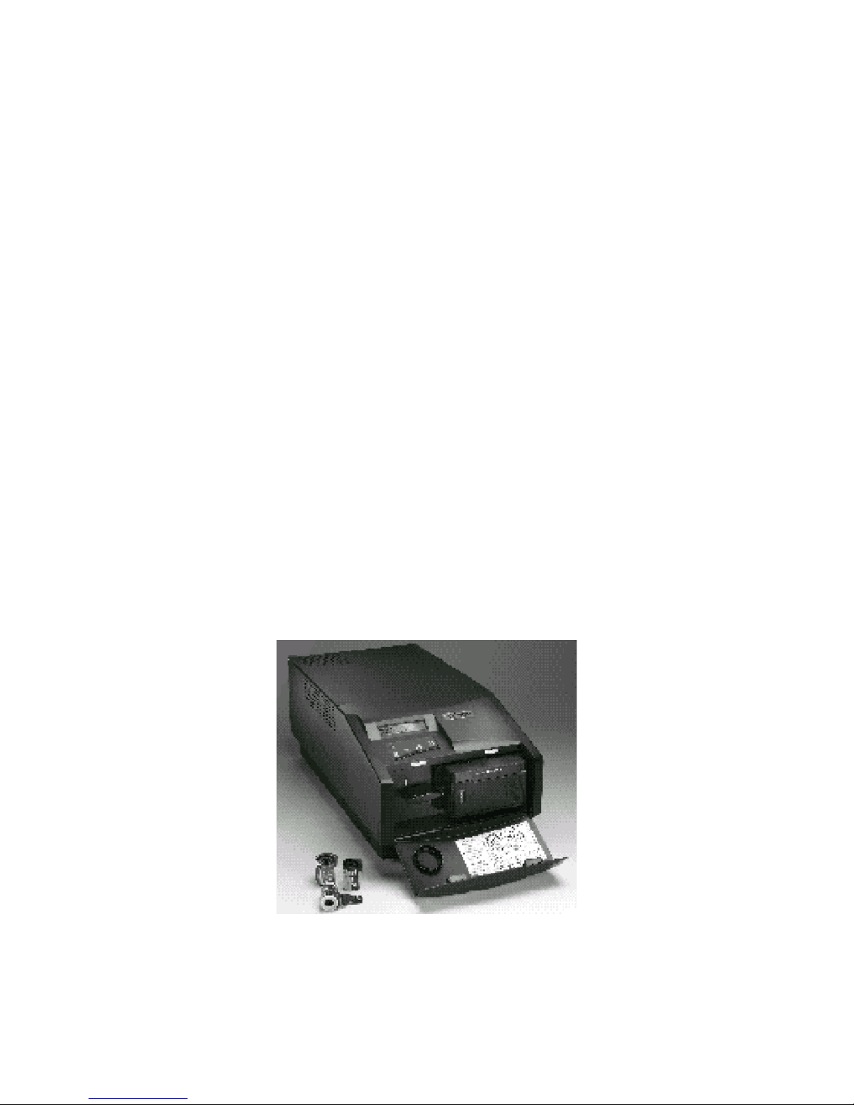
The Model 8035 (Figure 1-1) provides professional quality, continuous-tone 35mm color
negatives and transparencies with up to 8192 horizontal and 5460 vertical pixels
resolution. The Model 8035 uses a 35mm camera which has a 43.53mm, f/6, six element
lens. Positive, negative and instant 35mm film can be used and a bulk roll film adapter is
available for high-volume applications.
Figure 1-1. 8K Series ProPalette Model 8035
11
Page 12
8K Series ProPalette Repair Manual Description
The standard 35mm camera back automatically loads, counts exposures, and rewinds at
the end of each roll of film. (There is an option for early rewind.) System setup and status
is indicated via the 20-character, 2-line LCD panel.
Model 8035 can be expanded to produce 4x5 or 6x7 images through the purchase of
accessory camera backs. (Adding the camera backs also requires factory realignment.)
Model 8045 Description
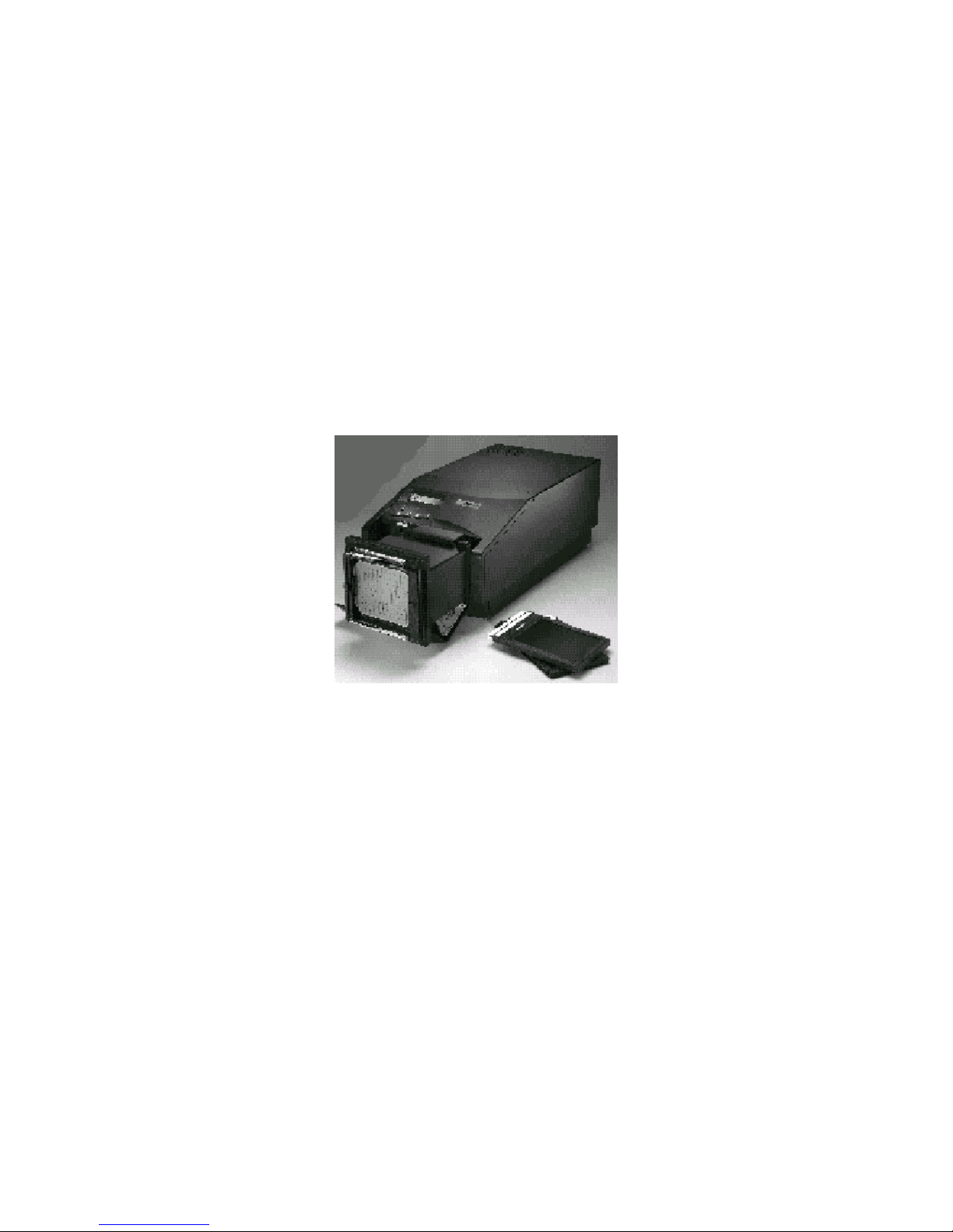
The 8K Series ProPalette Model 8045 (Figure 1-2) produces professional quality,
continuous-tone 4 x 5 images with up to 8192 horizontal and 6370 vertical pixels
resolution. The Model 8045 uses a 4x5 camera which has a 101mm, f/6.7, six element
lens. Positive, negative and instant 4 x 5 film can be used. System setup and status is
indicated via the 20-character, 2-line LCD panel.
Figure 1-2. 8K Series ProPalette Model 8045
Model 8045 includes a 35mm camera back which can replace the 4 x 5 camera back to
produce 35mm images. Additionally, Model 8045 can be expanded to produce 6 x 7
images through the purchase of the accessory 6 x 7 camera back. (Adding the camera
back also requires factory realignment.)
12
Page 13
8K Series ProPalette Repair Manual Description
Model 8067 Description
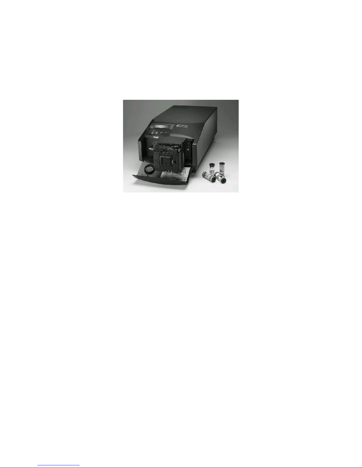
The Model 8067 (Figure 1-3) offers professional quality, continuous-tone 6 x 7 cm
images with up to 8182 horizontal and 6702 vertical pixels resolution. The Model 8067
uses a 6x7 camera which has a 74mm, f/5.5, six element lens. Positive and negative 6 x 7
film can be used. System setup and status is indicated via the 20-character, 2-line LCD
panel.
Figure 1-3. 8K Series ProPalette Model 8067
Model 8067 includes a 35mm camera back which can replace the 6 x 7 camera back to
produce 35mm images. Additionally, Model 8067 can be expanded to produce 4 x 5
images through the purchase of the accessory 4 x 5 camera back. (Adding the camera
back also requires factory realignment.)
8K Series ProPalette Factory Optimization
All 8K Series ProPalette film recorder models (8035, 8045, 8067) are factory-optimized
and matched to a specific camera during manufacture. Using a Polaroid Digital
Alignment Station at the factory assures that image quality, sizing, sharpness, location,
geometry and color saturation are all at peak level. These critical alignments result in
ideal match-ups between recorder and camera.
This process results in a film recorder with the highest level of precision which achieves
unprecedented image quality right out of the box. Each ProPalette model produces higher
resolution images than other film recorders in its product category.
Film Recorder Optics
The 8K Series ProPalette film recorders have a high-resolution, precision 7-inch CRT
with a proprietary anti-reflection and anti-static coating to render superb image sharpness
and purity. They also utilize custom optics with six element glass lenses and glass
dichroic filters to minimize spot size and maximize color saturation.
13
Page 14

8K Series ProPalette Repair Manual Description
Electronics
Auto-Luma /Auto-Chroma digital circuits automatically adjust brightness, luminance and
color balance. Digital geometry correction provides exacting straight lines and perfect
circles and eliminates pin cushioning, barreling and keystoning. Dynamic focus circuits
adjust the focus of the electron beam to assure consistent sharpness and clarity over the
entire image area. The system’s electronics adjust the focus of each image on the CRT
and use custom lookup tables for horizontal and vertical planes.
The 8K Series ProPalette provides 8000-line, continuously variable resolution for
recording images in their native, scanned resolution. This eliminates the image
degradation exhibited at lower resolutions and the need for time-consuming image
interpolation and decimation. The 8K Series ProPalette models are also designed for fast
printing: exposing a 35mm image at 4096 dpi requires less than 60 seconds.
The finished product is a 24-bit image with 36-bit color depth per pixel and 16.8 million
colors drawn from a palette of 68 billion colors. This results in smooth, ramped
backgrounds and accurate colors.
System Status LCD Panel
A 20-character, two line interactive LCD panel on the film recorder guides the user
through setup and also provides system status information during operation. A control
panel with a push-button menu system allows the user to send commands to the recorder.
Status/command functions are provided in choice of five languages and include:
• Storage of all setups in permanent
memory
• Image pixel dimensions displayed during
green exposure
• Firmware version and update status
• Automatic load/unload film status
• Detection of film jams/mis-thread
• Frames counted and frames available for
exposure
• Red/green/blue pass in progress
• Rewind film/advance film/remove
film/abort exposure
• Pacing indicators and waiting for host
warnings
• Previous error storage and information
retrieval
• Circuit board version information
• Unit serial number
• Calibration in progress
• SCSI ID, SCSI terminate settings
• Leader/no-leader selection
• Out-of film detection by end of roll or
frame count
14
Page 15
8K Series ProPalette Repair Manual Description
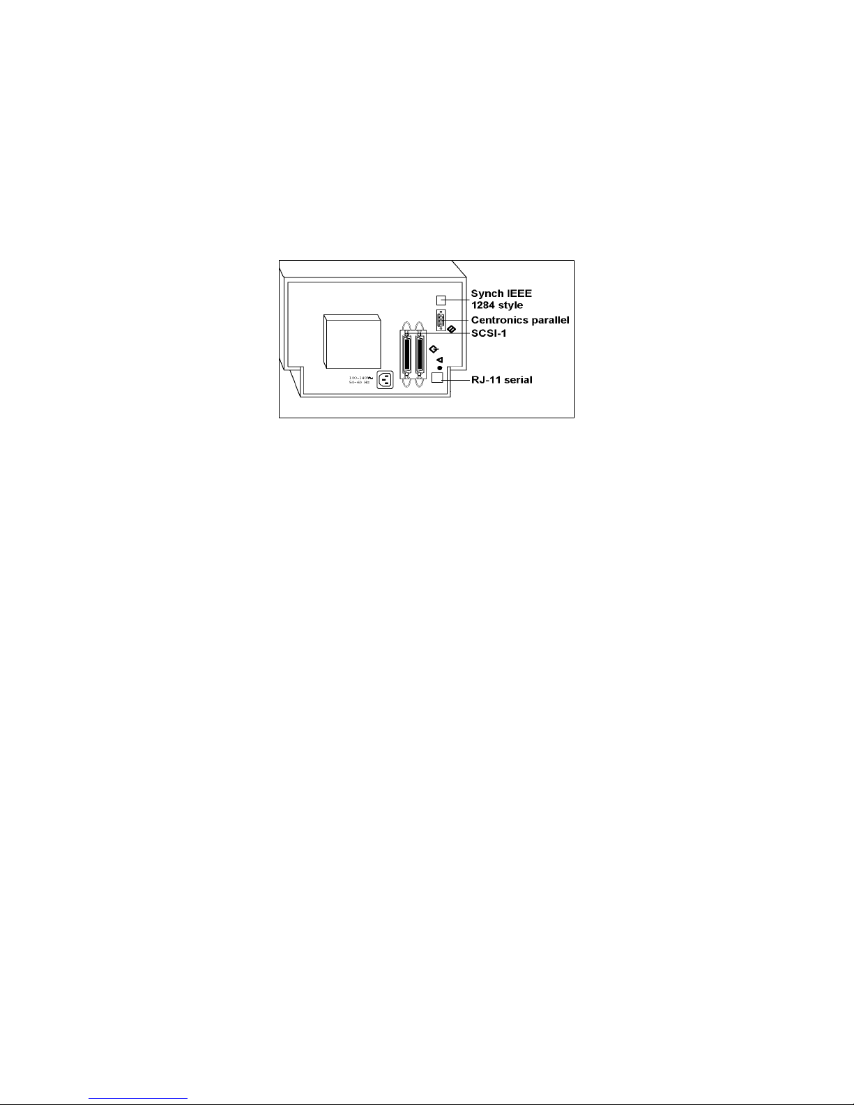
Ports
The 8K Series ProPalette models have four ports (Figure 1-4):
• Centronics parallel
• Synchronization IEEE 1284 style
• SCSI-1
• RJ-11 serial (available to service personnel only)
Figure 1-4. ProPalette Ports
Software and Interface Accessory Kits
The software provided in the Windows and Macintosh accessory kits is designed
specifically for ProPalette film recorders. Accessory kits are purchased separately.
ColorTune software matches the image seen on the computer monitor to the final image
created by the Propalette. This allows the user to perform more accurate previewing when
making adjustments to color and tone scale. ColorTune also enables the user to customize
film look-up tables to their individual workstation to obtain specific results.
Palette Export, an Adobe Photoshop export plug-in module allows printing directly from
Photoshop to produce continuous tone images quickly and simply.
The recorders can be networked with Palette for Windows (including Windows 95,
Windows 98, and Windows NT) and Palette for Macintosh. These software kits include
RasterPlus drivers.
All 8K ProPalette software has been tested for year-2000 compliance.
Accessory kits also include the appropriate cables for connecting the ProPalette film
recorder to Windows or Macintosh platforms.
The accessory kits are described in more detail in the following sections. For the PID
number associated with each kit, see Table 1-1 on page 17.
15
Page 16

8K Series ProPalette Repair Manual Description
Palette for Windows Kit
The Palette for Windows kit (for Windows 95, 98 and NT) consists of the following:
•••• RasterPlus for Windows. A print manager, including a queue feature for unattended
printing.
•••• ColorTune2 for Windows. Matches the film recorder output to the monitor image.
(This software is not included with the initial product release, but is available from the
Polaroid Web site. ColorTune2 for Windows will be included with later releases.)
•••• Polaroid Palette Export. Plug-in module compatible with Adobe Photoshop and
other popular image processing applications
•••• Parallel cable. Allows ProPalette to be connected to the PC via a parallel port.
RasterPlus for Macintosh Kit
The Raster Plus for Macintosh accessory kit is for use with G3 PowerMac systems, and it
provides Postscript compatibility. This kit includes the following:
•••• RasterPlus for Macintosh. A file-print and Postscript-compatible driver.
•••• Scheduler. A print-spooling utility allowing deferred printing.
•••• Palette Export for Macintosh. A plug-in for exporting images directly from
Photoshop.
•••• SCSI cable and terminator. Allows ProPalette to be connected to a Macintosh or
added to an existing SCSI chain.
Palette ColorTune for Macintosh is under development and currently not included in the
Raster Plus for Macintosh kit.
Palette for Macintosh Kit
The Palette for Macintosh accessory kit is for use with older 68K-based Macintosh
systems and does not provide Postscript compatibility. This kit includes the following:
•••• Palette for Macintosh. A chooser-level printer driver for all Macintosh computers
•••• SiPrint Assistant. A spooling utility for unattended printing.
•••• Palette Export for Macintosh. A plug-in for exporting images directly from
Photoshop
•••• SCSI cable and terminator. Allows ProPalette to be connected to a Macintosh or
added to an existing SCSI chain.
Palette ColorTune for Macintosh is under development and currently not included in the
Raster Plus for Macintosh kit.
16
Page 17

8K Series ProPalette Repair Manual Description
Accessory Kit PID Numbers
ProPalette software/interface components are summarized in Table 1-1.
Table 1-1. ProPalette Software/Interface Matrix
Operating
Name Vendor
Palette for Windows Kit
(includes the three items below)
RasterPlus for Windows Graphx Windows File-Print manager. Provides
Polaroid Palette Export for
Windows
Palette ColorTune2 for Windows
(not included with initial release)
Palette for Windows Upgrade
RasterPlus for Macintosh Kit
(includes the two items below)
RasterPlus for Macintosh &
Scheduler
Palette Export for Macintosh Polaroid Macintosh Photoshop export plug-in
RasterPlus for Macintosh
Upgrade
Palette for Macintosh Kit
(includes the three items below)
Palette for Macintosh & SiPrint
Assistant
Palette Export for Macintosh Polaroid Macintosh Photoshop plug-in utility
Palette ColorTune for Macintosh Polaroid Macintosh
Polaroid Windows Driver kit; includes parallel
Polaroid Windows Photoshop export plug in
Polaroid Windows Matches output to monitor by
Polaroid Windows
Polaroid Macintosh
Graphx Macintosh Driver and batching utility
Graphx Macintosh
Polaroid
System Description or Comments PID No.
101333
cable
PostScript & Queue capability
adjusting film tables
Intended fo r owners upgrading
to Windows 95 / 98 / NT;
includes all software in Palette
for Windows Kit above, but
does
requires RasterPlus 1.x or later
Driver kit for Power PC. (OS
7.5 or later, excluding 8.0);
includes SCSI cable and
terminator
Driver upgrade for owners
moving to RasterPlus for
Macintosh; includes all software
in the RasterPlus for Macintosh
Kit above, but does
SCSI cable or terminator.
Macintosh
V7.6 or later
Macintosh Drive r and batching utilit y
Driver kit for older 68K-based
Macintosh; no t Postscriptcompatible.
Film table tuner (matches output
to monitor)
include parallel cable;
not
not
include
101330
100197
101332
623879
This table is subject to change without notice.
17
Page 18

8K Series ProPalette Repair Manual Description
8K Series ProPalette Feature Summary
Feature Description Benefit
Custom optics Custom 6 element glass lenses;
35mm - 43.53mm, f/6; 4x5 101mm, f6.7; 6x7 - 74mm,
f/5.5; dichroic filters which
combine high transmittance
with sharp color cut-off; custom
CRT faceplate optics
Automatic exposure
and color balance
control
Electronics for automatically
setting optimum brightness and
color balance before exposure
of each image
Geometry correction Automatic digital correction of
geometry and linearity to
eliminate pincushion, barrel and
keystoning
Dynamic focus
adjustment
Automatic electronic focus of
the image on the CRT using a
lookup table customized for that
unit
Minimized spot size and
maximized color saturation
Bright images and accurate
colors
Distortion-free images with
straight lines and round
circles
Consistent clarity and
sharpness over entire image
area
High-resolution, 7in. CRT
Precision CRT with proprietary
anti-reflection / anti-static
coating
8K resolution Variable resolution with up to :
8192 horizontal and 5460
vertical pixels (35mm camera);
8192 horizontal and 6370
vertical pixels (4 x 5 camera);
8192 horizontal and 6702
vertical pixels ( 6 x 7 camera)
36-bit color depth 24-bit images with precision of
36 bits per pixel
Consistent clarity and
sharpness
Clearly defined details and
text
Printing in 16.8 million
colors, from a palette of 68
billion colors
18
Page 19

8K Series ProPalette Repair Manual Description
Feature Description Benefit
LCD display on
front panel
20-character x two-line
interactive display provides
setup and status information
Flash memory 4-megabyte DRAM, 512-
kilobyte flash memory
Multiple film
formats
Software and hardware support
for 35mm, 4x5, 6x7 and 35mm
bulk camera backs; cameraspecific film tables for multiple
E6, C-41, and Polaroid instant
films are included
Film tables Custom film tables for over 50
different 35mm, 120/220, and
4x5 films
Self diagnostics Unit performs a self-diagnostics
routine at startup. Routine can
also be initiated via the keypad
or host computer, if necessary
Easy to learn operation and
immediate understanding of
current status for efficiency
and productivity
Fast, simple upgrading of
firmware and product
enhancements
Flexibility to handle
expanding or changing
imaging needs
Provide maximum flexibility
for wide variety of film while
maintaining color and
exposure accuracy
Helps isolate problems
quickly and without special
tools or software
CRT access door Access to internal CRT from
beneath recorder
No potentiometer
adjustments
Operating and
service history
stored in memory
Manual optimization
unnecessary
Total exposures, film type used
for each, service history
information recorded in
nonvolatile memory for
reference
19
Allows easy cleaning of CRT
face
Fast, automated, accurate
calibration of individual units
Up-to-date operating and
service history available to
service technicians
Page 20

8K Series ProPalette Repair Manual Description
System Specifications
CRT
Optics
Image precision
Image quality
Color depth
LCD Display/Controls
Hardware
requirements
High resolution 7" CRT with anti-reflection & anti-static coating
All models - custom 6-element glass lenses:
35mm - 43.53mm, f/6
4x5 - 101mm, f/6.7
6x7 - 74mm, f/5.5
Glass dichroic filters
Custom CRT face plate optics
Automatic exposure and color balance control
Geometry correction
Dynamic focus circuitry
Any resolution up to a maximum resolution of 8192 horizontal x 5460
vertical lines (35mm); 8192 horizontal x 6370 vertical lines (4 x 5); 8182
horizontal x 6702 vertical lines (6 x 7)
36 bits per pixel (12 bits per color)
16.8 million colors per image from of a 68 billion color palette
20 character by 2 line interactive LCD display, 4-button command keys
PC environment:
•
Pentium class 150 mHz or faster processor
•
32 MB of RAM (64 MB for Windows NT)
•
15 MB program and 30 MB swap disk space
•
Windows 95; Windows 98; or Windows NT
•
DOS required for firmware upgrade utility
•
Parallel port or SCSI adapter card required
Memory
Macintosh environment: (Non-Power PC)
•
Palette for Macintosh
•
68K based Macintosh computer
•
System 7.6 or higher
•
SCSI interface
Macintosh environment (Power PC)
•
RasterPlus for Macintosh
•
Mac OS 7.5 or later (excluding OS 8.0)
•
PowerPC class processor
•
40 MB of RAM
•
10 MB of program and 30 MB of hard drive space
Unix environment:
Supported through third party manufacturer
4 MB DRAM for printer memory, 512 KB flash memory for firmware and
camera optimization data storage
20
Page 21

8K Series ProPalette Repair Manual Description
System Specifications (continued)
Postscript
compatibility
Network printing
Hardware interface
Available Supported
Cameras (all factory
matched to film
recorder)
Power source
Power consumption
Environment
Dimensions
RasterPlus for Widows software provides Level II PostScript compatibility
RasterPlus for Macintosh software provides Level III PostScript
compatibility
Palette for Macintosh software does not provide Postscript support.
Supported via software drivers on Windows and Macintosh systems
Parallel and SCSI (adapter required for Windows systems)
35mm camera
4 x 5 inch camera
6 x 7 centimeter camera
Bulk film 35mm camera
90-240 Vac, 50-60 Hz
Under 45 watts
Temperature: 50 to 100 degrees Fahrenheit (18 to 38 degrees Centigrade)
Storage Temperature: -20 to 160 degrees F (-29 to 71 degrees C)
Relative Humidity: 5 to 90 % non-condensing
11" x 28" x 8.5", (28 x 71 x 21.6 cm)
Weight
Certifications
Warranty
34 lb. (15.4 kg) (with 35mm camera)
UL, FCC, TUV, C-UL, CE, C-TICK, and EN55022 certification
One year parts and labor
Extended warranties available
21
Page 22
2 Hardware Operating Information
For the convenience of repair technicians, information in this chapter is excerpted from
the Polaroid ProPalette Installation Quickstart and Quickreference instruction guides
provided to ProPalette purchasers.
Installation Quickstart
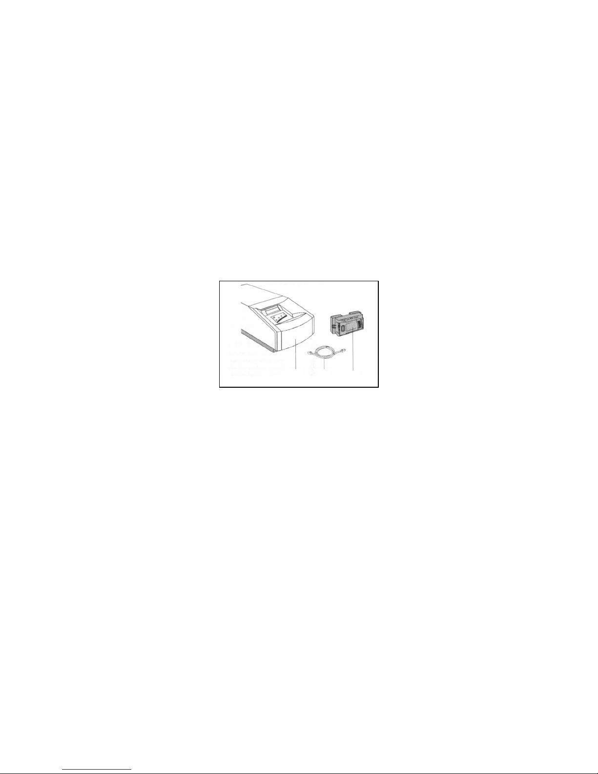
Unpack the Box
Make sure you have all the following components. Contact your dealer if any is missing
or damaged.
1
2
3
Figure 2-1. Unpacking
1. Film recorder (Figure 2-1)
2. Power cord
3. 35 mm camera back (mounted on film recorder) (Also, as applicable, 4x5
camera back and/or 6x7 camera back)
Also included but not shown in Figure 2-1 are a Quick Start, quick reference and
registration cards.
8K Series ProPalette software and connecting cables must be purchased and are in a
separate box. Model 8045 includes a 4x5 camera back; model 8067 includes a 6x7
camera back.
Position the Film Recorder
Place the film recorder at a convenient working height on a flat, vibration-free surface.
Make sure that all four rubber feet are in contact with the surface, and that the ventilation
holes are not obstructed. Position the film recorder away from any electro-magnetic fields
such as computer monitors or electric motors.
22
Page 23

8K Series ProPalette Repair Manual Hardware Operating Information
Connect the Film Recorder
ProPalette film recorders have a parallel port (1 in Figure 2-2) for connection to a
Windows 95 or 98 computer, and a SCSI port (2 in Figure 2-2) for connection to either a
Macintosh computer or to a Windows 95, 98 or NT computer with a SCSI host adapter
installed. (The parallel connection cannot be used with Windows NT systems.) The
power cord connects at 4 in Figure 2-2, and item 3 is the reset button.
1
2
3
4
Figure 2-2. Rear panel of film recorder
The software kit for Windows systems includes a parallel cable, but you can connect your
system to the SCSI port if you have a SCSI host adapter installed and a SCSI connection
cable (not included).
If you install a SCSI host adapter, follow the instructions provided by the adapter
manufacturer. (Host adapters may not be available for some iMac computers.)
Parallel Connection (PC with Windows 95 or 98)
Note: The parallel port must be configured as ECP in the PC
BIOS.
1. Turn off the PC and the ProPalette (Figure 2-3).
Figure 2-3. Film recorder On/Off switch
2. Connect the power cable to the ProPalette (Figure 2-4) and plug the cable into
AC power.
Figure 2-4. Connecting to power
23
Page 24
8K Series ProPalette Repair Manual Hardware Operating Information
3. Connect the parallel cable to the parallel port on the ProPalette and to the
parallel port on the computer.
Figure 2-5. Connecting cable to ProPalette parallel port
4. Turn on ProPalette and wait for it to complete initialization; (READY shows
on the display).
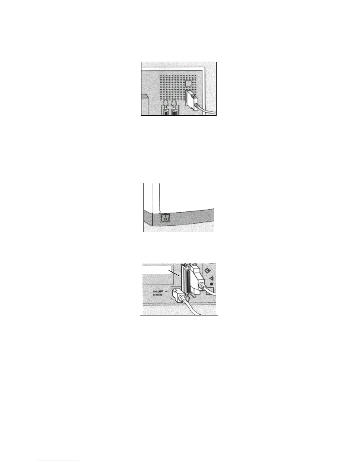
SCSI Connection (PC or Mac)
1. Turn off both your computer and the ProPalette.
Figure 2-6. Turn off ProPalette
2. Plug in a power cable to connect the ProPalette to power.
SCSI port
Figure 2-7. Connecting power cable and SCSI cable
3. Plug the 50-pin end of the SCSI cable into one of the SCSI ports on the rear
panel of the ProPalette and secure the connection.
4. Plug the 25-pin end of the SCSI cable into the SCSI port on your computer
and secure the connection.
5. Turn on ProPalette and wait for it to complete initialization (READY shows
on the display).
24
Page 25
8K Series ProPalette Repair Manual Hardware Operating Information
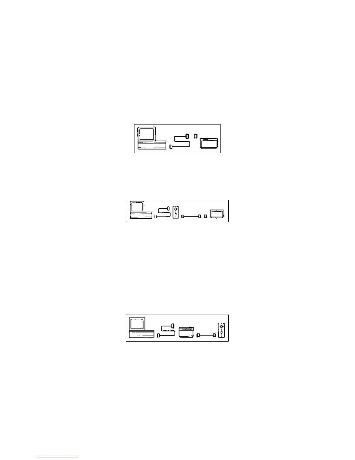
Note: SCSI device chains must be terminated once at each end of
the chain. The host adapter terminates one end. You must
terminate the other end. The following figures show three
typical connections.
In Figure 2-8, ProPalette is the only SCSI device and must be terminated. This
example shows external termination using a separate terminator (not
included). The ProPalette may be terminated internally instead (see below).
Connect the SCSI terminator either between the SCSI cable and the ProPalette
or to the second SCSI connector on the ProPalette rear panel.
Figure 2-8. SCSI connection #1
In Figure 2-9, ProPalette is the last device in the SCSI chain and must be
terminated. Figure 2-9 shows external termination using a separate terminator
(not included).
Figure 2-9. SCSI connection #2
The ProPalette may be terminated internally instead. (See “Terminating the
ProPalette Internally” on page 28.) Connect the SCSI terminator either
between the SCSI cable and the ProPalette or to the second SCSI connector on
the ProPalette rear panel.
Note: Do not terminate ProPalette both internally and externally.
In Figure 2-10 ProPalette is in the middle of the SCSI chain and must not be
terminated.
Figure 2-10. SCSI conection #3
25
Page 26

8K Series ProPalette Repair Manual Hardware Operating Information
Connection Tips
• When you connect or disconnect a SCSI device, make sure all SCSI devices have their
AC power switched OFF.
• Always make SCSI connections firmly, connecting the clips or tightening the screws
that secure cables and terminators. Most problems with SCSI devices are connection
problems along the SCSI chain.
• Some devices, such as the ProPalette, have two SCSI ports. The cable can be connected
to either port without affecting the performance of your equipment.
• Each device on a SCSI chain must have a unique SCSI ID number. These numbers are
described in the following section.
• Wherever a 50-to-50 pin cable is required, be sure to use a cable which meets the
SCSI-2 specification, such as an Apple cable.
• If you are using a PC, the ProPalette can be connected to two host computers at once;
one via the parallel connector and one via the SCSI connector. The recorder will image
in the order the signal is received.
Install the Software
1 Turn on your computer.
2 Insert the Polaroid Palette Software CD-ROM into the drive.
3 Follow the appropriate instructions for your platform:
Power MAC or Power PC Windows 95, 98, or NT
a Select Polaroid 8K Series
ProPalette Installer.
a Wait for the 8K Series ProPalette
program to start. If it does not start, select
Run from the Windows Start menu.
b Follow instructions on the screen.
b Click Browse and select
POLAROID.EXE on the CD-ROM, then
click OK.
c Follow instructions on the screen.
4 Remove the CD.
5 Configure the RasterPlus software for the appropriate platform as described in
the following sections.
26
Page 27

8K Series ProPalette Repair Manual Hardware Operating Information
Configure RasterPlus for Macintosh
For Power Macintosh and PowerPC systems, use the following steps to configure
RasterPlus for Macintosh software:
1 On the first launch of RasterPlus for Macintosh, personalize RasterPlus by
filling in the fields on the personalization screen and clicking OK.
2 Select your film recorder model and click OK.
3 Enter your desktop printer model (not the film recorder) and click OK.
4 Click Interface on the film recorder menu (the menu name matches the film
recorder selected in step 2) to confirm communication with the film recorder.
5 Click Camera Options on the film recorder menu and select the appropriate
camera back and film type.
6 Click Application Preferences on the Edit menu and set preferences for
schedule, files, previews, output log, network and miscellaneous items.
Configure RasterPlus for Windows
For Windows 95, 98 or NT systems, configure RasterPlus95 with the following steps:
1 Start the PC and the RasterPlus software.
2 Add the print driver and set device properties as follows:
a In Graphx RasterPlus95, click Global Properties on the Tools menu.
b Click the Device Manager tab.
c Select your film recorder under Available Devices and click Install.
Note: Graphx RasterPlus95 drivers are based on the Microsoft/ Adobe
PostScript core driver (PSCRIPT.DRV). If you have not yet installed
any other PostScript printer on your system, the software may
prompt you to insert and/ or specify a path which points to your
Microsoft Windows 95 installation CD so that it can copy
Microsoft’s PostScript driver files to your hard disk
d Select your film recorder under Devices installed in Microsoft Windows and
click Connect.
e Select the printer port to which your printer is connected in the Select Printer
Connection dialog box and click OK.
f Click Properties.
27
Page 28

8K Series ProPalette Repair Manual Hardware Operating Information
g On the Paper tab, select the appropriate page size.
For example, select PowerPoint if you are using the Microsoft PowerPoint
application, or select 35mm if you are using a 35mm camera back in another
application.
h Click the Device Options tab and select the appropriate film type from the
Change Setting for: Film Type list.
i Click the Graphics tab and select a resolution from the Resolution list.
j Click OK to save your properties settings.
k Click Close to close the Global Properties dialog box.
3 Select the queue properties as follows:
a Click Queue Properties on the Edit menu and click the Device tab if
necessary.
b Select the recorder you are using from the Device list.
c Select the port to which the film recorder is connected from the
Connection list (LPT or SCSI port).
d Click the Options button.
e Click the Info button in the [Device] Options dialog box.
4 Wait for film recorder information to appear on the screen, indicating that the
software is communicating with the ProPalette.
If an error message states that the recorder is not connected or is turned off,
the software cannot communicate with the ProPalette. If this happens, make
sure the ProPalette is properly connected (see “Connect the Film Recorder” on
page 23), turned on, and the correct port is selected on the Device tab of
Queue Properties.
Terminating the ProPalette Internally
1. Turn off the computer and all other SCSI devices.
2. Turn on the ProPalette and wait for it to complete initialization; (READY
shows on the display).
3. Press to display the Change Setup? menu on the message panel.
4. Press
until SCSI Terminated? appears.
28
Page 29

8K Series ProPalette Repair Manual Hardware Operating Information
5. Press , then press or to highlight Yes (terminate) or No (turn off
termination).
6. Press
, then press twice.
7. Press the Reset button on the back of ProPalette.
Changing the ProPalette SCSI ID
Caution: If two devices on a SCSI chain have the same SCSI ID
number, neither will work correctly, and data may be
damaged when you turn on the devices.
The preset ProPalette SCSI ID is 4. If the SCSI ID of
any other device is 4, either change the SCSI ID of that
device (consult the device documentation) or of
ProPalette.
1. Turn off the computer and all other SCSI devices.
2. Turn on 8K Series ProPalette.
3. Press to display the Change Setup? menu on the message panel.
4. Press until SCSI ID? appears, then press to display the current SCSI ID
number.
5. Press to select an unused SCSI ID number.
Note: The SCSI host adapter is usually ID 0, and most internal
SCSI hard drives are ID 1. An internal SCSI CD-ROM
drive may be ID 3.
6. Press , then press twice.
7. Press the Reset button on the back of 8K Series ProPalette.
29
Page 30
8K Series ProPalette Repair Manual Hardware Operating Information
Controls, Indicators and Connectors
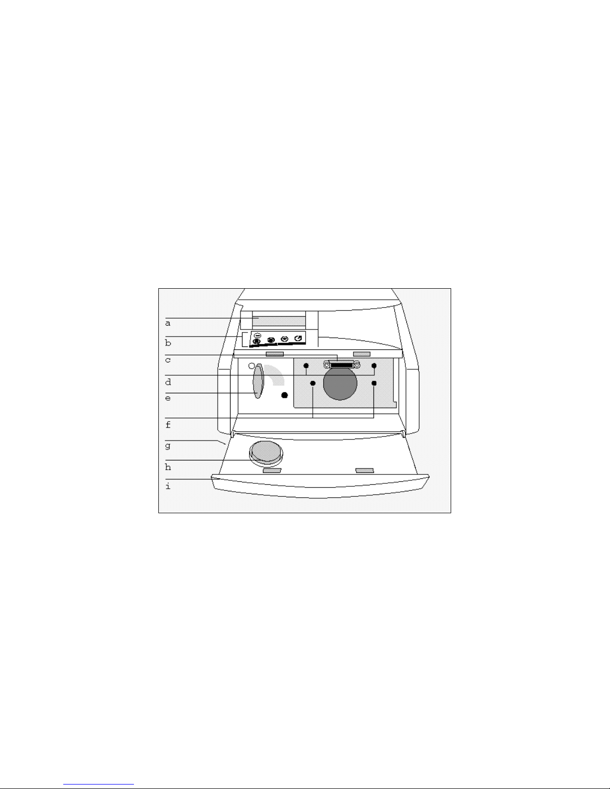
Front (Without Camera)
The following controls, indicators and connectors on the front of the 8K Series ProPalette
unit are shown in Figure 2-11:
a. Message panel
b. Keypad
c. Camera connector
d. Attachment holes for optional camera backs
e. Camera locking lever
f. 35mm Camera positioning holes
g. Power OFF/ON (0/1) switch (beneath door)
h. Lens cap holder and lens cap
i. Front cover
Figure 2-11. Front controls, indicators, features
30
Page 31

8K Series ProPalette Repair Manual Hardware Operating Information
Keypad
The 8K Series ProPalette keypad controls and indicators are identified in Figure 2-12.
Figure 2-12. Keypad controls and indicators
Using the 35mm Camera Back
35mm Camera Back Description
The 35mm camera back provided with the recorder features automatic film loading,
advancing and rewinding for maximum convenience. The camera can detect the length of
the film, and counts frames as exposures are made. This information is displayed on the
message panel for reference.
Refer to Figure 2-13 for the location of the following camera back components:
a. Film door button
b. Film ID window
c. Film door
d. Edge connector
e. Lens
f. Positioning pins
Figure 2-13. 35mm camera back
31
Page 32

8K Series ProPalette Repair Manual Hardware Operating Information
Loading 35 mm Film
1. Verify that the 35 mm camera back is properly attached, and turn the film
recorder on (Figure 2-14).
Figure 2-14. Turn on film recorder
2. Slide the film door button on the camera back down (Figure 2-15) and open
the door.
Figure 2-15. Open camera back door
3. Insert the film cassette at an angle into the chamber (Figure 2-16). Push the
cassette in fully, so that the film lies flat against the track.
Figure 2-16. Insert film cassette into camera
Note: Do not touch the shutter when loading the film.
32
Page 33

8K Series ProPalette Repair Manual Hardware Operating Information
4. Pull the end of the film gently to the right (Figure 2-17) until the end reaches
1/2-inch past the white triangle at the lower right. (If you pull the end of the
film too far, remove the cassette, turn the black knob at the top of the cassette
to wind the end back in, and reinsert the cassette into the chamber.)
Figure 2-17. Pull film to right
5. Close the film door until you hear a click. The message panel (Figure 2-18)
displays Loading Film, the film advances, then the message panel displays
the number of exposures available.
Message
panel
Figure 2-18. Film recorder message panel
6. Close the front door.
Using the 4x5 Camera Back
The 4x5 camera back is shown in Figure 2-19.
Figure 2-19. 4x5 camera back
33
Page 34

8K Series ProPalette Repair Manual Hardware Operating Information
Loading 4x5 Film
1. Verify that the 4x5 camera back is properly attached and secured, and turn the
film recorder on (Figure 2-20).
Figure 2-20. Turn on film recorder
2. In a darkroom, load the 4x5 film holder with film. Orient the film with the
notch positioned as shown in Figure 2-21.
Notch
Figure 2-21. Orienting film in holder
Note: Some 4x5 films are available in Ready-load packages.
When used with the Polaroid 545 or the Kodak Readyload
Packet filmholder, you can load the film holder outside of a
darkroom.
3. Pull open the outer section of the camera back enough, but no more than 2
inches, to slide the film holder in (Figure 2-22).
Figure 2-22. Inserting film holder into camera back
Caution: Do not pull the outer section too far. This can cause the
camera back to pop out of the springs and require
Service Center repair.
34
Page 35

8K Series ProPalette Repair Manual Hardware Operating Information
4. Insert the 4x5 film holder into the camera back from the right.
Note: To avoid light leak, make sure that the left side of the film
holder lies snugly against the left side of the outer section
of the camera back.
5. Wait for the message panel to display a message directing you to pull out the
dark slide.
6. Pull out the dark slide (Figure 2-23) before exposure.
Figure 2-23. Pull out dark slide
Note: Remember to reinsert the dark slide after exposure.
7. Gently push any button on the keypad to confirm dark slide removal.
Using the 6x7 Camera Back
The 6x7 camera back is shown in Figure 2-24.
Figure 2-24. 6x7 camera back
Loading 6x7 Film
1. Verify that the 6x7 camera back is properly attached and secured, and turn the
film recorder on (Figure 2-25).
Figure 2-25. Turn on film recorder
35
Page 36

8K Series ProPalette Repair Manual Hardware Operating Information
2. Steady the camera insert with your left hand, and pull the top latch on the film
door up and the bottom latch down with your right hand. Remove the camera
insert (Figure 2-26).
Figure 2-26. Removing camera insert
3. Note the pressure plate dial setting (Figure 2-27). If the black arrow is
pointing to the type of film (120 or 220 length) you are loading, proceed to
step 5.
Dial
Figure 2-27. Check the dial setting
If the black arrow is not pointing to the correct film type:
a Hold the camera insert in your left hand. Do not set it down on a flat
surface.
Note: Make sure you’re fingers are not touching the pressure
plate on the back of the camera insert.
b Push in the pressure plate dial (Figure 2-28) and turn it clockwise until
the arrow points to the film you are loading (as printed on the film
package).
Figure 2-28. Resetting the pressure plate dial
36
Page 37

8K Series ProPalette Repair Manual Hardware Operating Information
4. Turn the camera insert around, verify that the film type appears in the display
window (Figure 2-29), and check that the plate is locked into position.
Figure 2-29. Check film type in window
If the plate is not locked into position, turn the pressure plate dial slightly until
it snaps into position.
5. Turn the camera insert so that the OFF/ON switch is on the bottom. If the
empty spool is on the right (take-up) side, proceed to step 6.
If the empty spool is on the left side:
Figure 2-30. Swing out spool
a. swing out the left spool retainer, remove the empty spool, and swing in the
left spool retainer.
If the empty spool is on the right side:
b. swing out the right spool retainer, insert the empty spool, and swing in
the right spool retainer.
6. Turn the film roll so that the film feeds toward the back of the camera insert
(Figure 2-31).
Figure 2-31. Load film so it feeds to back of insert
37
Page 38

8K Series ProPalette Repair Manual Hardware Operating Information
7. Swing out the left spool retainer. Insert the film roll (Figure 2-32). Swing in
the left spool retainer.
Figure 2-32. Load film onto spool
8. Pull out and wrap the film around the back of the pressure plate until the end
reaches the take-up spool (Figure 2-33).
Figure 2-33. Wrap film around pressure plate to take-up spool
Caution: Do not pull the film out too far. Doing so will fog part
of the film and reduce the number of available
exposures.
9. Insert the end of the film into the take-up spool slot. Turn the film advance
knob counterclockwise (Figure 2-34) until the arrows on the film roll line up
with the red arrow on the left spool retainer.
Figure 2-34. Insert film into take-up spool
Note: If the film does not wind evenly. remove the spool, take out
the film. and reinsert the end of the film into the take-up
spool slot and restart rewinding.
38
Page 39

8K Series ProPalette Repair Manual Hardware Operating Information
10. Open the camera back. Check that the top and bottom latches are fully open.
Seat the camera insert tightly onto the camera back (Figure 2-35).
Figure 2-35. Open camera door to check latches
11. While holding the camera insert onto the camera back, close the film door
(Figure 2-36). Hold the door shut while pushing the top latch down and the
bottom latch up.
Figure 2-36. Close film door
Note: If the door does not shut and latch easily, reseat the camera
insert tightly onto the camera back.
12. Check the control lever positions on the top of the camera back (Figure 2-37).
If the control levers do not point to the white squares, turn the levers until they
point to the white squares.
Figure 2-37. Check control lever position
13. Turn the camera back OFF/ON switch to ON (Figure 2-38).
Figure 2-38. Turn camera switch to ON
39
Page 40

8K Series ProPalette Repair Manual Hardware Operating Information
14. Press the START button on top of the camera back (Figure 2-39) to advance
the film to the first exposure.
Figure 2-39. Press START button
15. Pull out the dark slide (Figure 2-40) before exposure.
Figure 2-40. Pull out dark slide
Locking the Film Type Via the Keypad
The film type must always be selected in the software and it must match the film loaded
into the recorder to ensure proper color balance and exposure. If the recorder is on a
network, it may be inconvenient for remote users to confirm which film type is currently
loaded into the recorder. If so, you can “lock in” the film type you have just loaded using
the keypad. Doing so will prevent users from making exposures on the incorrect film type
(an error message will alert the user).
When the film type is “unlocked” (not selected via the keypad), no error message is sent.
In this case, remote users should check which film is loaded before imaging.
To lock the film type:
1. Press the Escape key to reach the Change Setup menu.
2. Press the Down key until “Lock Film Type?” is displayed. Press the Select
key. “*Unlocked” or the name of the currently locked film is displayed.
3. Press the Down (or Up ) key to display the film type that is currently loaded.
Or, select Unlocked to allow any film type to be selected in the software.
4. Press the Select key to enter the selection. An asterisk (*) will appear next to
your selection to indicate it has been selected. Press Escape twice to return to
the Ready message.
40
Page 41

8K Series ProPalette Repair Manual Hardware Operating Information
Locking the Camera Type via the Keypad
A camera-locking function has been added to the 8K Series ProPalette LCD/keypad
menu. This function allows the operator to bypass the camera auto-sense and manually
select the camera installed on the system.
The available menu options are:
• Auto Sense (default)
• 35 mm
• 4 x 5
• 6 x 7
• 6 x 8
• Bulk 35 mm (see the following section, “Bulk Camera Support”)
To lock the camera type:
1. Press the Escape key to reach the Change Setup menu.
2. Press the Down key until “Lock Camera Type?” is displayed. Press the Select
key. The name of the current selection is displayed.
3. Press the Up or Down key to display the desired camera type.
4. Press the Select key to enter the selection.
5. Press Escape twice to return to the Ready message.
Bulk Camera Support
The 8K Series ProPalette models (8035, 8045, 8067) support the bulk camera back
manufactured by Double M. The ProPalette automatically detects the bulk back and
displays “35-mm bulk” when it is attached. To expose bulk images, use the standard
35mm drivers and film tables.
The bulk camera can also be selected by manually setting the camera type to “Bulk 35
mm” as described in the previous section.
Leaving a Film Leader
It is more convenient to process Polaroid Polachrome HC instant 35mm film if a short
length of film (a “leader”) remains extended from the cartridge after the roll is exposed
and rewound. To set the camera back to leave a leader after rewinding, do the following:
1. Press the Escape key to reach the Change Setup menu.
41
Page 42

8K Series ProPalette Repair Manual Hardware Operating Information
2. Press the Down key until “Leave Leader?” is displayed.
3. Press the Select key, then press the Down key to display “Yes.”
4. Press the Select key to enter the selection. Press Escape twice to return to the
Ready message.
Note: Select No under “Leave Leader?” when reloading
conventional 35mm film to rewind the film completely into
the cartridge.
Making Exposures
Once you have loaded the film, the Ready status message will be displayed on the
message panel. You are now ready to begin initiating exposures from the software. (Be
sure to select the correct film type in the software.)
Before an exposure is started, "READY" appears on the first line of the LCD display.
When a 35 mm camera is mounted, the second line of the LCD display alternates
between the camera name with its serial number and the frame count status. If any other
camera is mounted, the camera name and its serial number appears on the second line.
Note: The displayed camera serial number was stored in flash
memory at the factory when the camera was matched to the
ProPalette. The ProPalette does not read the camera serial
number from the camera.
When you begin your first exposure, the unit may do a brief calibration routine first (the
message panel will display “Calibrating.”).
During the exposure, the message panel displays information about the process. The top
line indicates the color is being exposed and the line count being exposed. The second
line of the display changes and depends on the color is being exposed. During the RED
exposure, the second line displays the selected film type. During the GREEN exposure,
the second line displays the image resolution. During the BLUE exposure, the second line
displays the current frame count.
After each exposure, the panel will count down the frames available (for example, “23
Frames Left of 24”). When the last exposure is finished, the message panel will display
“Out of Film.” Remove the exposed film as described in the following section.
Note: When you turn off the recorder with a partially exposed roll
loaded, the recorder keeps the status information in
memory and will redisplay the correct frame count when
you turn on the recorder again.
42
Page 43

8K Series ProPalette Repair Manual Hardware Operating Information
Removing Exposed Film
When you are finished exposing a roll of 35mm film, the camera will automatically
rewind the film. The message panel will then display “Out of Film.” Open the front door
of the recorder, open the film door, and remove the film cassette. The film should be
completely rewound into the cassette unless the film leader option has been selected as
described on page 41.
Rewinding a Partially Exposed Roll
To rewind a partially exposed roll of film, press the Escape key to display the Change
Setup menu. Press the Down key until “Rewind Film” is displayed. Press the Select key.
The film will rewind, and the message panel will display “Out of Film” when done.
Remove the film.
Note: Do not try to reinstall a partially exposed roll of film.
Advancing Film
If you need to advance film (leave unexposed frames) during a session, press the Escape
key to display the Change Setup menu. Press the Down key until “Advance Film?” is
displayed. Press the Select key; the film will advance one frame. To advance the film by
more than one frame, repeat this sequence the desired number of times.
Note: This option is useful if a power failure occurs during an exposure.
Advance the film by one frame, then reshoot the image on the next frame.
Or, if you accidentally opened the film door when a partially exposed roll
was loaded, advance the film by a few frames to bypass the light-fogged
area of film.
Removing and Replacing the 35mm Camera Back
To remove the 35mm camera back:
1. Open the front cover of the recorder.
2. Move the locking lever to the unlocked ({) position (Figure 2-41, left).
3. Carefully pull the camera back straight off (Figure 2-41, right). Replace the
lens cap, which is stored in the front cover, while the camera is not in use.
Figure 2-41. Removing and replacing the camera back
43
Page 44

8K Series ProPalette Repair Manual Hardware Operating Information
To replace the camera back:
1. Remove the lens cap and store it in the holder in the front door.
2. Be sure the locking lever is set to the unlocked ({) position.
3. Push the 35mm camera back gently but firmly onto the mounting plate so the
positioning pins fit in the holes, and so the edge connector fits snugly into the
slot in the recorder. Turn the locking lever to the locked (z) position.
Enhanced Information Display
On the 8K Series ProPalette models, the current film table name appears on the LCD
display during the red exposure to help prevent film table selection mistakes.
The actual resolution (in pixels) also displays during the green exposure. This feature
demonstrates the unique ProPalette variable resolution capability (i.e., bitmap images
exposed at their native resolution without time consuming and image degrading pixel
interpolation or re-rendering).
Artifact Warning Indicators
On the 8K Series ProPalette models (8035, 8045, 8067), the LCD warns when the host
computer is unable to maintain the steady supply of pixel data needed for artifact-free
images. (The artifacts are thin dark horizontal lines, particularly noticeable in pastel
regions of the image.)
The warning sign appears in front of the line number during the exposure and remains
visible until the next image. The symbol displayed indicates the delay time in the data
and the likely impact on the image as follows:
Display Wait Time
underscore ("_") 200 msec May produce artifacts
dash ("-") 400 msec [TBD]
equal sign ("=") 600 msec Likely to produce artifacts (thin, black,
horizontal lines)
If artifact warnings occur, the operator should do one of the following to avoid artifacts:
• Turn on "buffer to disk" if the software driver supports it.
• Shut down unnecessary applications competing with the driver.
• Move images from a heavily loaded network to a local drive.
Impact
• Rotate, crop, or scale before starting the exposure.
• Add more memory, disk space , or CPU power to the PC.
• Increase the pacing setting via the keypad or the driver.
44
Page 45

8K Series ProPalette Repair Manual Hardware Operating Information
Hardware Configuration Display
On the 8K Series ProPalette models, the diagnostics menu command "Show Power On
Msg?" has added functionality to aid diagnostics during telephone support and service.
This command displays the film recorder model, firmware version, firmware date and
firmware time. After 10 seconds, the ProPalette serial number (if entered during
manufacturing) and the hardware configuration numbers of the three main circuit boards
appear.
High Density Grids
On the 8K Series ProPalette models, high-density grids are enabled. The operator sees an
"initializing" message at startup or when cameras are swapped.
The high-density grids are being calculated and stored in RAM during this time. Note
that the 4x5 camera may require four or five minutes to initialize.
Protecting the CRT and Camera from Dust
Follow these guidelines to protect the CRT and camera from dust:
• Keep a camera back on the unit when it is not in use.
• When the camera back is not mounted on the recorder, use the lens cap
provided.
Cleaning the CRT Face
The CRT inside the recorder has an anti-static coating to help protect it from smoke and
dust particles. But if dust appears on the CRT, clean it as follows.
1. Turn the power off and disconnect the power cord.
2. Turn the recorder on its side.
3. Unscrew and remove the access door on the bottom.
4. Carefully reach in and remove the dust on the surface of the CRT with a dry
cotton swab (Figure 2-42). Avoid touching the filter wheel and filters.
Figure 2-42. Cleaning the CRT face through the bottom access door
45
Page 46

8K Series ProPalette Repair Manual Hardware Operating Information
Cleaning the Camera Lens
Remove the camera back and hold it with the lens facing up. Remove as much dirt as
possible with an aspirator, pressurized air, or a camel hair brush, available at a camera
store. If necessary, wipe the lens with a cotton-tipped swab moistened with lens cleaner
(Figure 2-43). Do not soak the swab so that the lens is flooded with cleaner. Examine the
surface of the lens for scratches and replace it if any are found.
Caution: When cleaning the lens, do not use strong detergent
solutions, abrasives of any sort, or aromatic solvents
such as acetone or MEK.
Figure 2-43. Cleaning the camera lens
Testing the Hardware Installation
To verify that the recorder is imaging properly without connecting the unit to a computer,
you can use the keypad to initiate a test image exposure as follows:
1. Remove the 35mm camera to allow observation of the CRT through the lens
opening in the recorder.
2. With the Ready message displayed, press the Escape key to reach the Change
Setup menu.
3. Press the Down key until “Diagnostics?” appears. Press the Select key, then
press the Down key to display “Expose Test Image?”
4. Press the Select key to begin the test exposure cycle, and view the CRT
through the camera opening.
A row of red spots should be moving down the screen, and a horizontal line
should be flashing intermittently. This cycle repeats for the green and blue
filters. (Figure 2-44 shows the image this pattern would create on film.)
Figure 2-44. 8K Series ProPalette test image
46
Page 47

8K Series ProPalette Repair Manual Hardware Operating Information
If you do not see the spots and horizontal line described in step 4, there is a
problem with the hardware or hardware installation. Check your cable
connections before looking further.
If the test was successful but you cannot image from a software package, the
problem could be software-related. Check the software manual or contact the
manufacturer of the application software.
If a loaded 35 mm camera is attached to the ProPalette when the Self Test is
initiated, the shutter opens just prior to the RED exposure and closes at the
end of the BLUE exposure. There is no change to any frame count and the
film must be advanced with the keypad controls. This allows verification of
camera functionality.
Troubleshooting Hardware and Film Probl ems
This section describes symptoms and solutions for problems with hardware setup and use
of the 35mm camera/adapter. Refer to the software manual for troubleshooting software
problems. Also refer to Chapter 4 for additional troubleshooting information.
Black image (film not exposed): The shutter did not open, the lens cap was left on
the camera, or the preview function of the RasterPlus95 has deleted the image file.
Random black spots: Caused by dirt specks on the CRT. Clean the CRT.
Dark, or pale colored horizontal lines across image: Make sure the recorder is
properly grounded (including extensions and multiple outlet strips), use only the
cables supplied with the recorder, protect the unit from bumps or vibrations during
exposure; data wait lines as a result of a slow host computer.
Image too light or dark; incorrect color balance: Make sure the correct film type
has been specified in the software; see the software instructions for details.
Color Balance and Exposure for Negative Film
When using color negative film, color balance and exposure can vary over a wide range
due to the variability of processing and printing at the processing lab. If exact color
matching is important, shoot the test image at the beginning of each roll and have a
custom lab calibrate the equipment to that image for color balance and exposure before
printing the roll. The image is equivalent to an 18% gray card.
Macintosh users: The test image GRAYCARD is in the Print Me Later folder.
PC users: The test image GRAYCARD.TIF is copied onto your hard drive at
installation. Import this file into your application software for imaging.
47
Page 48

8K Series ProPalette Repair Manual Hardware Operating Information
Running a Self-Test
If you wish to run the diagnostic self-test that the recorder performs at power-up without
turning the recorder off and on again, you can do so using the keypad.
Press the Escape key to reach the setup menu. Press the Down key until “Diagnostics?” is
displayed. Press the Select key, then press the Down key to display “Run Startup Diags?”
Press the Select key to begin the brief self-test.
Redisplaying an Error Message
When the system detects one of a number of hardware or software problems, it briefly
displays an error message on the message panel. The same message may also appear on
your computer. The recorder will automatically reset.
If the problem persists, press the Escape key to reach the setup menu. Press the Down key
until “Diagnostics?” is displayed. Press the Select key, then press the Down key to
display “Show Last Error?” Press the Select key; the most recent error message will be
displayed for your reference.
LCD Panel Messages
The message: is displayed when:
Ready
x Frames Left of Y
(35mm only)
Loading Film Film is being loaded after the film door is closed
Calibrating You initiate the first exposure of each session, and as
Exposing RED The red data is being exposed through the red filter.
Exposing GREEN The green data is being exposed through the green filter.
Exposing BLUE The blue data is being exposed through the blue filter.
Rewinding Film Film is being rewound at the end of the roll, or after you
Unit is ready to expose.
Film is loaded and there are frames left to expose (where x is
the number of frames left and y is the length of the roll).
Note: To reach Change Setup? press Escape (see the
following section, “Setup Menu Reference”).
necessary after that. “Calibrating” appears only when
resolution has changed.
select Rewind Film? to rewind a partially exposed roll (see
the following section, “Setup Menu Reference”).
Out of Film Film is completely exposed and ready to be removed, or no
film is loaded.
48
Page 49

8K Series ProPalette Repair Manual Hardware Operating Information
The message: is displayed when:
Change Setup? You press Escape from the Ready message. Select this to
change setup (see the following section, “Setup Menu
Reference”).
[One of several error
messages]
There is a problem with the recorder or the software. The
recorder will automatically reset. To view the error message
again, see “Redisplaying an Error Message” on page 48.
Initializing During parameter calculation, when implemented.
Film Type During Red exposure (V564 or higher)
Resolution During Green exposure (V564 or higher)
49
Page 50

8K Series ProPalette Repair Manual Hardware Operating Information
Setup Menu Reference
To reach the Setup menu, press Escape at the “Ready” message.
Menu Options See page
Change Setup 43
Rewind Film? 43
Advance Film? 43
Lock Film Type? *Unlocked 40
Film type 1
Film type 2
Film type ...n
Lock Camera Type? *Auto Sense 41
35mm
4 x 5
6 x 7
6 x 8
Bulk 35mm
Leave Leader? No 41
Yes
SCSI ID? [current #] 29
*4
5
6
7
1
2
3
SCSI Terminated? *No
Yes
Language? English?
German?
French?
Spanish?
Italian?
Diagnostics? Expose test image?
Run Startup Diags?
Show Last Error?
Power On Message?
Pacing Disable, 5 - - 24ms 77
28
Legend:
Note:
•
If no key is presse d within a few seconds, “Change Setup?” changes to “UP DN SEL ESC” to help
you identify the keys.
•
If no key is pressed for several seconds while in the setup mode, the display automatically returns to
the ready mode. Press Escape again to return to the setup mode.
•
After making a selection, press Escape until the Ready message appears.
•
Wherever the Down key is shown, the Up key c an also be used to scroll through options.
Up Down Select Escape
50
Page 51

8K Series ProPalette Repair Manual Hardware Operating Information
Activating Monitor Mode
Monitor mode refers to the rudimentary operating system hard-coded into the ProPalette
on-board microprocessor. It provides base level control and communication between the
ProPalette unit and the host computer through the ProPalette serial port.
Monitor mode can be activated by any of three methods: (1) front panel buttons, (2)
digital board jumpers, and (3) LCD menu.
Activating Monitor Mode Via Front Panel Buttons
Note: Monitor mode can be activated via the front panel buttons only on
ProPalette models with digital board 1F5570A Is06 or later
(generally ProPalette models 8035, 8045 and 8067, and ProPalette
7000 and 8000 models with upgraded digital boards). This method
also works with earlier digital boards if EPROM U103 has been
upgraded with the ProPalette ROM v548 P/N 102423.
To activate Monitor mode via the front panel buttons:
1 Turn the ProPalette power switch to off.
2 While pressing and holding the scroll up and scroll down buttons, turn the
power switch on.
3 Release the scroll up and scroll down buttons.
Note: This method also disables the watchdog timer.
To return to normal mode, turn the system off and back on or press the reset button.
Activating Monitor Mode Via Digital Board
To activate Monitor mode via the digital board:
1 Turn the ProPalette power switch to off.
2 Jump J3-6 and J3-8 on the digital board to ground. (All pins along the bottom
of J3 are at ground potential.)
3 Turn the ProPalette power switch to on.
Note: The LCD panel does not operate when you activate
Monitor mode in this manner, so there is no indication that
the mode is active. You must run a terminal emulator for
the serial port to verify that the EEPROM has control.
Return to normal mode by turning the system off, removing the jumpers, and turning the
system back on.
51
Page 52

8K Series ProPalette Repair Manual Hardware Operating Information
Activating Monitor Mode Via LCD Menu
Note: The LCD menu cannot be used when the ProPalette
firmware is corrupted (only a blinking cursor appears on
the LCD display when the unit is powered on). In this case,
you must activate Monitor mode via the front panel buttons
or the digital board as described in the previous sections.
To activate Monitor mode via the LCD menu:
1 Turn the ProPalette power switch to on.
2 Select Diagnostics from the top level LCD menu.
3 Select Go To Monitor Mode from the second level menu.
The LCD panel displays “Film Printer in Monitor Mode.”
Return to normal mode by pressing the reset button on the back of the ProPalette unit.
Displaying or Changing the Stored Serial Number
This section describes the use of the host side DOS utility SN.EXE, which displays or
changes the serial number stored in the ProPalette flash memory.
Serial number storage was implemented in the ProPalette with firmware version 564. The
serial number is stored in flash memory and is used by the firmware to define the correct
system parameters based on the hardware configuration associated with the serial
number.
The executable SN.EXE either displays the current serial number and board versions or
changes the serial number.
Viewing the Stored Serial Number and Board Versions
To view the serial number and circuit board version numbers stored in the ProPalette
flash memory, execute the following command from a DOS window:
sn
By default, the utility accesses the COM1 port of the host computer.
The utility’s help file is accessed with the command: sn ?
52
Page 53

8K Series ProPalette Repair Manual Hardware Operating Information
The command displays a report similar to the following:
sn, Reports and optionally sets serial number
Version 564/704
Compiled on Jun 12 1998
The current film printer number is :
serial number = 8A6020H
Analog version = 4
Digital version = 7
Video version = 2
For more information about ProPalette serial number syntax, see “Serial Number Syntax”
in the next section. Board versions are listed on page 103.
Serial Number Syntax
The serial number is made up of six fields:
• Model (P)
• Month of mfg. (M)
• Year of mfg.(Y)
• Sequential count (nnn)
• Product revision (R)
• CRT identifier (C)
These fields are arranged in the serial number as follows:
P M Y nnn R C
The following table identifies the information provided by each serial number field:
Serial No. Field Meaning
P ProPalette model: ProPalette 8000 Plus
M Month of manufacture:
A = Jan D = Apr G = Jul K = Oct
B = Feb E = May H = Aug L = Nov
C = Mar F = Jun J = Sep M = Dec
Y
nnn
R
Last digit of manufacturing year
Sequential manufacturing count during month
Product revision letter
C
Example: PG9052SW
This serial number identifies a ProPalette 80xx manufactured in July 1999. It
was the 52
nd
unit manufactured that month, it is a “S” revision, and it has a
model “W” CRT.
Manufacturer and model of CRT
53
Page 54

8K Series ProPalette Repair Manual Hardware Operating Information
Changing the Stored Serial Number
To change the serial number stored in the ProPalette flash memory, execute the following
command:
sn -burn=<string>
where <string> is the serial number to be stored in flash memory.
By default, the utility accesses the COM1 port of the host computer.
The utility’s help file is accessed with the command: sn ?
Viewing and Interpreting the Error Log
The host-side utility, ERRSTAT.EXE, allows viewing of the ProPalette error log for
troubleshooting purposes. For more information about the error log and messages that
can be stored there, see “Error Logging (ERRSTAT.EXE)” on page 99.
Enabling and Disabling the Watchdog Timer
The ProPalette watchdog timer prevents power-on initialization errors. The watchdog
timer is normally on, but must be disabled for performing some service procedures such
as running the Flash Manager utility described on page 153.
The watchdog timer can be enabled or disabled by changing the position of the jumper on
JP501 of the digital board (1F5570A) as follows:
Watchdog timer enabled: Jump pins 2 and 3 on JP501
Watchdog timer disabled: Jump pins 1 and 2 on JP501
The watchdog timer is also disabled when the ProPalette monitor mode is activated via
the front panel keys as described on page 51.
54
Page 55

3 Theory of Operation
Design Objectives
The goals of ProPalette design are as follows:
• Reliable
• Easy-to-operate
• Continuous and variable resolution from 512 to 8K
• Fast exposure
• Parallel and SCSI port support
• High image quality (high sharpness, optimized geometry, low
vignetting)
• Optimized manufacturability
Image Quality Objectives
ProPalette design provides high image quality as follows:
Image Quality Parameter Method
Sharpness 7-inch CRT, high voltage focus
Geometry Direct digital control of horizontal and vertical
deflection via D/A converters
Vignetting (dark corners) Direct digital control of cosine4 signal via D/A converter
Manufacturability and Serviceability
In the 8K Series ProPalette models, manufacturability and serviceability have been
improved by eliminating all potentiometers and eliminating the need to perform any
adjustments on the CRT. In addition, a new automatic alignment system determines
optimum geometry settings and focus voltages, factory-matching the camera to the
recorder. After the optimum settings have been determined, the values are stored in the
ProPalette flash memory.
The 8K Series ProPalette models reduce exposure times via the method of exposing each
pixel line in a single horizontal scan instead of multiple horizontal scans.
55
Page 56

8K Series ProPalette Repair Manual Theory of Operation
CPU
ProPalette’s CPU is a V53 (Intel 186 compatible) with a TI DSP. It also has 4 megabytes
of DRAM (expandable to 14 megabytes at the factory), and a field-upgradeable 512
kilobyte flash firmware memory.
Deflection and Geometry Control
Pixel deflection is controlled digitally via a 2D lookup table, 16-bit DAC, sample and
hold and a low-pass filter. Instead of magnets on the CRT yoke, the 8K Series ProPalette
models correct geometry (pincushion) digitally through the 2D, 16-bit lookup table
customized at the factory for each unit and stored in flash memory.
Sharpness Control
The ProPalette provides dynamic focus through a 2D lookup table and a 12-bit DAC. The
lookup table is customized for each unit at the factory and stored in flash memory. The
system also reduces pixel degradation in the corners by correcting for spot astigmatism
with internal neck magnets.
Exposure Control
ProPalette controls exposure as follows:
Exposure Parameter Control Method
Pixel brightness Intensity-modulated 1D lookup table and 16-bit
DAC
Compensation for CRT
brightness drift (Autoluma)
12-bit ADC with 8-bit gain control, providing more
than 20 bits of dynamic range. Brightness is
checked before each exposure and corrected when
necessary.
Compensation for CRT
phosphor color balance drift
COS4 (compensation for
Periodically recalibrated via photocell viewing CRT
through the filters.
2D lookup table and 12-bit DAC.
brightness fall-off at corners)
56
Page 57

8K Series ProPalette Repair Manual Theory of Operation
ProPalette Major Systems
The ProPalette uses the major hardware systems in Table 3-1 to create images on
photographic film. The systems are interconnected as shown in Figure 3-1.
Table 3-1. ProPalette Systems
System Function
Filter Wheel
Assembly
Places appropriate color filter between the CRT and camera lens
upon command from the Digital board. Provides wheel-position data
to the Digital board via a photo-interrupter that detects notches in the
filter wheel.
Low-Voltage
Power Supply
High-Voltage
Converts line voltage to supply necessary power to the other
ProPalette components
Provides required high voltages to the CRT.
Power Supply
Digital Board Contains the ProPalette CPU, flash memory, EPROM, DRAM. The
Digital board digital signal processing (DSP) subsection provides
CRT horizontal deflection, vertical deflection, video and dynamic
focus data to the Analog board. Modules on the Digital board also
control the camera, LCD and keypad, filter wheel and photointerrupter.
Analog Board Uses input from the Digital board and Autoluma board to produce
output for producing an image on the CRT assembly.
Autoluma
Board
Monitors CRT illumination using a photodiode and provides controls
to maintain correct CRT brightness.
CRT Displays an image from analog board input.
Camera The camera focuses the CRT image onto the film. Some camera
backs (35mm and 6x7) also advance and rewind the film when
commanded by the digital board.
LCD/Keypad
Assembly
Displays status indicators and error messages on an LCD display.
Also allows operator to enter commands and change options from
menus via a four-key keypad. Interacts with the LCD/keypad module
on the Digital board.
57
Page 58

8K Series ProPalette Repair Manual Theory of Operation
Figure 3-1. ProPalette systems block diagram
58
Page 59

8K Series ProPalette Repair Manual Theory of Operation
Exposure System
Exposure Sequence
ProPalette uses the latent memory of photographic film to record light and to blend the
shapes and colors from a sequence of colored exposures. The exposures are made from
black-and-white, computer-generated video scan lines.
Upon command from the host computer, ProPalette creates a black-and-white video scan
line for a specified amount of time on the CRT. When projected onto film through lenses
and colored filters, a series of these scan lines creates a full-color image on the film. This
sequential exposure technique combines exposures of each primary color to produce
almost any shade or hue.
Exposure System Components
Figure 3-2 shows a simplified representation of the ProPalette exposure system. It
consists of a camera back/adapter assembly, a filter wheel assembly, a filter wheel photointerrupter that provides wheel position information, an autoluminance photodiode
assembly to sense CRT brightness, and the CRT assembly.
Figure 3-2. ProPalette exposure system
Camera Back/Adapter Assembly
Several camera back assemblies are available for use with various ProPalette models.
Each camera back includes a fixed-focus, fixed-aperture lens. (ProPalette controls
exposure via the intensity and duration of the CRT scan lines.)
Filter Wheel Assembly
The filter wheel assembly positions the appropriate colored filter (red, green or blue)
between the CRT and the film. Filter movement is initiated by the host computer, which
issues a command to ProPalette to rotate the filter wheel until the appropriate filter is in
position.
59
Page 60

8K Series ProPalette Repair Manual Theory of Operation
The filter wheel has four positions:
Position 1. Red filter (start position)
Position 2. Green filter.
Position 3. Blue filter.
Position 4. Opening without a filter, for viewing the CRT during testing and
calibration.
If a command from the host computer requires the filter wheel to turn to a higher filter
position, the filter wheel rotates directly to the specified position. If the instruction is to a
lower filter position, the microprocessor control circuit directs the filter wheel to rotate to
the start (1) position, and then to the requested position.
Filter Wheel Photo-Interrupter
On the rim of the filter wheel are notches that are detected by the filter wheel photointerrupter. The photo-interrupter contains a LED and a photo-transistor. When a notch
on the filter wheel passes between the LED and the photo-transistor, the photo-interrupter
generates a pulse that is detected by the microprocessor control circuit.
By counting the pulses from the photo-interrupter, the microprocessor on the ProPalette
digital board determines the position of the filter wheel and starts or stops the stepper
motor as necessary to position the filters correctly.
Filter Wheel Stepper Motor
The filter wheel stepper motor rotates the filter wheel assembly using a small rubber
roller on the motor shaft. Using information from the filter wheel photo-interrupter, the
microprocessor control circuit on the digital board increments the stepper motor as
needed to move the filter wheel to the proper position.
Autoluma Board
The autoluma board consists of a photo-diode and associated circuitry. It provides a
voltage output that is proportional to the light seen by the photo-diode.
Power Supply
AC Power
ProPalette operates with domestic or international commercial AC power applied through
the main power switch and the voltage selector.
Note: ProPalette meets domestic and international power
requirements. It operates from 100/115 to 220/240 volts at
50/60 Hz commercial AC power.
60
Page 61

8K Series ProPalette Repair Manual Theory of Operation
When the main power switch is on, AC power is applied to the low voltage power supply.
An LED on the front of the ProPalette unit indicates that the unit is powered.
DC Power
Regulated DC voltages are generated from the low voltage power supply. They are
applied to the analog board through connectors J31, J32 and J37, and to the digital board
through J4. These voltages power the following:
• Digital board
• Analog board
• High voltage power supply
• Filter wheel stepper motor
• Camera back via connector
• Small system computer interface (SCSI)
The DC power system is shown in Figure 3-3.
Figure 3-3. Power supply interconnection diagram
61
Page 62

8K Series ProPalette Repair Manual Theory of Operation
Digital Board
Digital Board Circuits
The ProPalette digital board contains circuitry for communicating with the host
computer, controlling operations, and executing commands from the host computer
software. The digital board functions are:
• SCSI Interface
• Parallel Interface
• Serial Interf ace
• Random access memory (RAM)
• Video signal generation
• Vertical deflection, Horizontal deflection, COS4 control, dynamic focus
• Frame synch signal generation
• Autoluminance (CRT brightness) control
• ProPalette operations (camera back, stepper motor, filter wheel position sensing)
Digital Board Components
The digital board has the following components, interconnected as shown in Figure 3-4:
• NEC V53 micro-controller (main processor or CPU)
• Serial port (internal to the V53)
• RS232 driver/receiver
• I/O decoding logic
• Boot/monitor EPROM
• DRAM controller, 4MB base DRAM and two DRAM SIMM sockets for up to
10MB of additional DRAM
• 512KB flash memory
• TI TMS320C26 DSP
• DSP I/O decoding logic
• Two 8Kx8 high speed SRAMs
• Multiple data latches between the V53 and DSP
• Camera back interface with DX code support
• Color filter wheel driver circuit
• LCD/keypad interface
• SCSI port (SCSI-2 compatible) with active terminators
• Parallel port with standard Centronics compatibility and an expansion connector
with access to the V53 data bus, address bus and control signals.
62
Page 63

8K Series ProPalette Repair Manual Theory of Operation
Figure 3-4. Digital board block diagram
63
Page 64

8K Series ProPalette Repair Manual Theory of Operation
Digital Board Functional Groups
Digital board functions have been classified into four groups as shown in Table 3-2.
Table 3-2. Digital board functional groups
Group
No. Functions Description
1
• V53 CPU
• EPROM
• I/O decoding logic
• RS232 driver/receiver
2
• First MB of DRAM and associated logic
• Remaining DRAM (3-13MB)
• 512KB flash memory
• DSP and communications with V53
• 8K word DSP SRAM
3
• Parallel port
• SCSI port
4
• Filter wheel stepper motor control
• Camera back interface circuit
• LCD/keypad module interface
Must be operational for the system to
work at the lowest level. (If any
function in this group is inoperable,
the digital board cannot
communicate with the host system,
even at the lowest level.)
Do not require special external
hardware to verify (tested by onboard CPU).
Require parallel and SCSI interface
hardware and test software on the
host PC (tested by connecting the
digital board to a PC with parallel
and SCSI cables, then running
programs to verify communication
between the PC and digital board).
Cannot be tested by the on-board
CPU or host PC, but are tested
implicitly during board level testing.
• Analog board data and control I/O
• Sync (alignment) outputs
64
Page 65

8K Series ProPalette Repair Manual Theory of Operation
Group 1 Functions
Flash Memory
512KB of Flash memory is used to store the firmware, film tables, CRT calibration data,
autoluma data, the frame count, SCSI bus ID and various other volatile data types. At
power-on, the film printer copies the firmware from Flash memory to DRAM and runs it.
The current Digital Board design employs a single 5V-only flash chip that sits on the V53
buffered data bus. The chip, an AM29F400T, is used exclusively in the byte mode. The
V53 address lines connect to the address inputs and the V53 memory read and memory
write outputs drive the flash output enable and write enable inputs. The RCTL1WT PAL
asserts a chip select signal, whenever the V53 addresses the upper 2Meg of its 16Meg
address space.
V53 Timer0 (Real Time Ticker)
The V53 has several internal timers including Timer0 which is used to generate a
periodic OS interrupt or clock tick.
Group 2 Functions
DSP and Communications with V53 and DSP SRAM
A diagnostic routine built into the firmware verifies the DSP is working, checks all of the
communications between the V53 and the DSP and tests the 2 8Kx8 DSP SRAMs.
When the DSP is in the 'hold' state, the V53 has direct access to the DSP SRAM and the
DSP I/O devices.
Group 3 Functions
Parallel Port, J19
Parallel port hardware consists of the ECP_PORT PAL (Lattice pLSI1016-60), one
74ACTQ646 8-bit bi-directional bus transceiver, one 74AC245 8-bidirectional buffer and
one 74ACTQ244 8-bit buffer.
SCSI Port, J14
SCSI port hardware consists of a XX53C94 SCSI controller I.C., a UC5601 active
terminator I.C. and a 20 pin resistor pack. The SCSI controller is connected to the V53
data bus, the V53 buffered data bus and four V53 address lines.
65
Page 66

8K Series ProPalette Repair Manual Theory of Operation
Group 4 Functions
Filter Wheel Stepper Motor Control, J5 & J6
Two high-voltage, medium current dual peripheral drivers (75477) generate
PHASE1/PHASE2 and PHASE3/PHASE4 which turn on and off current in four stepper
motor windings. One side of each stepper motor winding is tied to +15Vdc and the other
side attaches to the low-side drivers (PHASEX). PHASE1 and PHASE 2 should always
be the complement of each other.
The same relationship applies to PHASE3 and PHASE4. Three 82C55 output bits control
the peripheral drivers. INTLED provides current for an LED photo-interrupter which
outputs a logic signal, FWSENSE, to indicate when a filter wheel slot is front of the
sensor.
Camera Back Interface Circuit, J13
The camera back interface is made up of one 74VHC244 8-bit buffer, one 74HC273 8-bit
latch, one 74HCT257 quad 2-to-1 mux, one LM311 comparator, two 75477 medium
current low-side drivers, one 2SA1314 PNP power transistor, one 754410 (or L293D)
dual half H-bridge and one LM317 linear voltage converter. The 8-bit buffer serves as an
input port for signals output from the camera back. DX code bits are selected for reading
via the 2-to-1 mux.
Both the 8-bit buffer and the 8-bit latch sit on the V53 buffered data bus, VBD7-0. The 8bit latch controls the camera shutter and film motor via control outputs fed to the 2 lowside drivers, the dual half H-bridge and an open-collector driver connected to the base of
the PNP power transistor. The remaining 8-bit latch bits serve as the select bit for the 2to-1 mux and the perforation sensor LED On/Off control. The comparator translates the
perforation signal from the camera to a valid logic level. The voltage converter steps
15Vdc down to 6.4Vdc to supply the half H-bridge output driver.
LCD/Keypad Module Interface, J12
This interface consists of one 8-bit 82C55 port for LCD module data bus lines, four more
82C55 outputs for LCD module and backlight control, four 82C55 inputs for reading
keypad keys, one 2SA1314 PNP power transistor for driving the LCD backlight and 1/2 a
74HC20 4-input NAND gate for generating a key interrupt to the V53.
Analog Board Data and Control I/O, J18
The Digital Board outputs a number of data and control signals which connect to devices
on the Analog Board.
66
Page 67

8K Series ProPalette Repair Manual Theory of Operation
Analog Board
The ProPalette analog board contains all the D/A and A/D converters required for full
digital control of the CRT deflection, luminance, video and focus. A single 64-pin ribbon
cable connects the analog board to the digital board. This cable carries a 16-bit bus (a
buffered version of the DSP data bus) and various control signals.
Figure 3-5 is a block diagram of the analog board.
Digital bus
(from/to Digital board)
COS4
dynami c
focus
4
COS
0-10 V
Dynamic
focus
amplifie r
Video
DAC
Video
driver
Analog Board
DAC
latches
Vert digital input
Horiz digital input
Video digital input
Horizontal
Video
feedback
sample
and hold
DAC
Horiz.
Trimd ac s
(8 bit )
Horiz size
Horiz center
Vert size
Vert center
Serial bus
(fro m / t o
Digital board)
Vertical
DAC
Vertical
sample
and hold
From
Autolu ma
boar d
AL_INPUT
Autoluma mult, offset , luma lo, luma hi
Dynamic focus output
Dynamic focus feedback
To H .V .
power supply
Horiz
Vertical
low-pass
filter
Vertical
yoke
driver
Vert
feedback
Luma
circuitry
Horizontal
low-pass
filter
Horizontal
yoke
driver
feedback
To CRT cathode To CRT coil To CRT coil To CRT grid
Figure 3-5. Analog board block diagram
67
Page 68

8K Series ProPalette Repair Manual Theory of Operation
The analog board also contains the autoluma circuitry, shown in the block diagram in
Figure 3-6.
Figure 3-6. Autoluma circuitry on analog board
Slowscan Description and Imaging Sequence
This section provides a description of the ProPalette slow scan exposure process and the
activities that the TMS320C26 DSP performs during an exposure.
The DSP has direct control over five D/A converters to control the CRT:
• X deflection- DAC
• Y deflection- DAC
• Video- DAC
• Cos4- DAC
• Dynamic Focus - DAC
68
Page 69

8K Series ProPalette Repair Manual Theory of Operation
For a slow scan exposure, the three DACs for deflection and video are updated to scan
the beam. The Cos4 and Dynamic Focus DACs are updated at a slower rate.
The design goal is to be able to expose an image on 35mm film in less than 1 minute. The
exposure process includes some startup time where a brightness auto-calibration is
performed, and the exposure of three color planes; red, green, and blue. Between the
exposure of each color, the color wheel must be moved.
The time to expose a line includes the time required to sweep the crt beam horizontally,
displaying all of the pixels, and the time to retrace the crt beam to the beginning of the
next line.
The mix of activities performed by the DSP, and dedicated hardware have been chosen to
accommodate the major activities of:
• Generation of deflection values for the X and Y deflection DACs
• Generation of Cos4 and Dynamic Focus values
• Generation of video DAC values at the pixel rate.
Grid for Deflection
Digital grid point information representing horizontal, vertical, video, COS4 , and
dynamic focus data is sent to the DSP which operates on the information and controls the
output timing of this data to the analog board.
Video DAC Data Generation
Pixel data is provided from the host computer as either RGB data or in a RLE format.
RLE data is converted to raw RGB pixels. RGB data is a byte per pixel per primary color.
For each primary color, we have a byte value which indicates the density of that primary
color for each pixel.
This pixel data must be converted to video DAC data. This is a non-linear conversion
which must accommodate both the contrast of the CRT and the non-linearity of the film.
There is a non-linear one-to-one correspondence between the pixel value and the video
value. Throughout this documentation we make a distinction between pixel data and
video data. Pixel data is a byte value which represents the brightness of a pixel. Video
data is a 16 bit value to the video DAC to get that brightness on film.
Hardware is dedicated to do a pixel-to-video conversion at the required throughput rate.
The hardware is a 256 word memory which is loaded with a video lookup table. The
memory is addressed with the pixel value and the output is the video value. A DMA
channel is dedicated to sending the pixel data from it's memory to the lookup table and
the output of the lookup table is sent to the video DAC.
69
Page 70

8K Series ProPalette Repair Manual Theory of Operation
For each primary color, the V53 must load the video look-up table with pixel-to-video
values. This is a 256 word table. Before the exposure of a each line, the V53 initializes
it's video DMA channel with a pointer to the beginning of the pixel data in it's DRAM for
that line.
Exposure Summary
The V53 must have the following information available before an exposure begins:
• Grid point data for X and Y deflection
• Grid point data for Cos4 and DyFocus
• A DRAM memory pipe filled with pixel data for the current
primary color. While the exposure proceeds, the V53 must keep
up with generating pixel data for subsequent lines. If the
availability of pixel data starts to fall behind, then the exposure is
slowly and gracefully throttled down so that the exposure rate
matches the delivery rate of pixel data from the host.
There are two V53 DMA channels dedicated to supplying data to the DSP. One channel
provides grid point data and the other supplies pixel data.
Flash Description
The flash devices in ProPalette are programmable, non-volatile memories which are used,
primarily, to store the control code and gridpoint data for the ProPalette system. Other
programs and data can be placed in the system such as diagnostics and control
information.
Flash Data Organization
The flash contains data blocks of various sizes. Each data block is preceded by a flash
header. The header contains information on what is in the data block and how large the
data block is.
The flash header structure is defined:
flash_data_type It lists all of the valid data block types which can reside in
flash.
data_length Length of the data block (excluding the header) in bytes.
software_version Version of the program which put this data block into flash.
This is not necessarily the version of the data or program in the block.
70
Page 71

8K Series ProPalette Repair Manual Theory of Operation
startup_segment The segment address of where this data goes. For data blocks
which are raw data, as opposed to programs, this value is 0. For data blocks
which are programs, this is where the programmed is moved when it gets
executed.
hdr_name A description of the data block type.
data_name Description of the data itself and is provided by the program which
actually puts the program in flash. For an executable, this is typically the name of
the program. For instance, for the CNTRL_CODE flash_data_type, the
hdr_name is 'Control Code' and the data_name would be something like 'kacntrl'.
There is no fixed order of data blocks in flash. They are programmed into flash as they
are received. Data blocks cannot be duplicated; there's only one copy of a given data type
in flash at any time. If a data block is to be programmed and an older copy already exists,
then the older copy is effectively overwritten.
Programs for Reading and Writing the Flash
Two low level programs are available to read and write the flash. Other programs can
include code to manipulate the contents of flash. For instance, kacntrl can put GridPoint
data into flash. The format of the GridPoint data is out of the domain of the general flash
programs and this data is only programmed by kacntrl.
The two low level general purpose programs which are available are the Flash Dispatcher
and the Flash Manager.
The Flash Dispatcher resides in EPROM and is able to read a directory and start any of
the programs which reside in flash.
The Flash Manager is a program which may reside in flash and be can be started by the
Flash Dispatcher. It can add data blocks, remove data blocks, and erase the entire flash.
Normally, production units do not have Flash Manager burned in flash. If Flash Manager
is needed, it can be loaded and executed from DRAM. For more information about using
the Flash Manager, see page 153.
When the system is started from a hard reset, startup code examines the state of the
startup switches on J3. The two startup switches, J3-6 and J3-8 provide four states:
State J3-6 J3-8
ROM Monitor gnd gnd
Debugger open gnd
Control Code (default) open open
Expansion Code gnd open
The ROM Monitor is started, using the first serial port as a console.
71
Page 72

8K Series ProPalette Repair Manual Theory of Operation
The Debugger is started, using the second serial port for talking to the remote debugger
which is running on the host.
When the switches are set to Control Code or Expansion Code, the EPROM version of
the Flash Dispatcher gets control.
If the switches are set for Control Code, the Flash Dispatcher moves the CNTRL_CODE
data block to DRAM and starts executing the code.
If the switches are set for Expansion Code, the EXPANSION_SWITCH data type is read
from flash. The data block in the EXPANSION_SWITH data type contains two pieces of
data; a program to run and a flag indicating whether this program should be directly
executed or whether it should be run using the debugger.
Autoluma Process
The autoluma calibration process measures the light emitted by the CRT using a photo
detector. This is done by varying the luma control output (G1) and video output while
scanning the CRT. The clear window of the filter wheel is in front of the solar cell at this
time to maximize the light measured by the solar cell.
The autoluma calibration process creates a data curve of video DAC input level vs. CRT
brightness (from the darkest to the brightest amount of light needed to expose the film
type chosen for the image). This curve is used to create a lookup table that maps pixel
values to video DAC values.
If the calibration process cannot find a CRT light level dark enough for the film, (i.e.
there is always light recorded by the solar cell) an error of “CRT not dim enough” will be
reported by the film recorder.
If the calibration process cannot find a CRT light level bright enough for the film (this
could mean that no light is emitted by the CRT), an error of “CRT not bright enough”
will be reported by the film recorder.
If the measured curve is not monotonically increasing from darker to brighter values, the
errors “luma not smooth” or “video not smooth” will be reported by the film recorder.
72
Page 73

8K Series ProPalette Repair Manual Theory of Operation
Firmware Description
Downloading New Firmware
New firmware can be downloaded to the ProPalette for storage in flash. The new copy
replaces the copy in the unit.
General Description
New firmware is sent to the Propalette in the Intel HEX format from the host computer.
After all of the hex data is transmitted, the firmware is burnt into the Flash. This process
takes about 40 seconds and the progress is displayed on the LCD. After the new firmware
is in flash, the ProPalette is restarted so that the new firmware is running.
Camera Back Interface
The ProPalette has a flexible camera back interface including a 400 mA shutter driver, an
X-connector input (for shutter control), a film door switch input, a film perforation sensor
input, a 500 mA bi-directional film motor driver, 6 DX code inputs for sensing ISO film
speed, +5V @ 2A and +24V @ 1.2A power outputs.
Camera backs connect to the ProPalette through a 20-pin edge connector suitable for a
double sided, 0.049" thick PC board with 10 signal conductors per side. The PC board
traces must be 0.040" +/- 0.005" wide on 0.100" +/- 0.005" centers.
The connector pinout is described in Figure 3-7 and Table 3-3. All 'inputs' are inputs
from the film recorder's perspective (outputs from the camera back). Control signal
timing may be individually adapted to the various camera back types when their interface
requirements are defined.
Figure 3-7. Camera connector pin numbers
73
Page 74

8K Series ProPalette Repair Manual Theory of Operation
Table 3-3. Camera Connector Signal Descriptions
Pin No.
Signal Name
Figure 3-7 Description
BLADE_MAG 1 Shutter magnet, active low -- driven low to hold
shutter open, released (floated) to close shutter.
Vlow = 0.6V max @ 300mA
BLADE_MOT 3 Shutter control signal, active low -- driven low then
high in conjunction with X-CON transitions to open
shutter.
Vlow = 0.6V max
Vhigh = CBVCC - 0.2V min @ 300mA
CBVCC 5 +5V for camera power. Protected against shorts with
internal 2A fuse.
GND 17 Return for all +5V camera circuitry.
CBPWR 14 +24V for camera power. Protected against shorts with
internal 2A fuse
+24V_RET 16 Return for all +24V camera circuitry.
35BACK_SW 7 Film door switch input. Pulled high to CBVCC with
10K ohms.
X-CON 9 X-connector input for shutter timing. Used with 35mm
camera. Pulled high to CBVCC with 10K.
PERF_LED(A) 11 Perforation LED anode. Used with 35mm camera.
PERF_LED(K) 15 Perforation LED cathode. Used with 35mm camera.
/35PERF_SENS
13 Perforation sensor voltage. Used with 35mm camera.
E
FILM_WIND(-) 19 Film wind/rewind motor drive signal. First half of
500mA full H-bridge driver
Vhigh = 5.5V - 6.0V
Vlow = 0.6V - 1.4V @500mA
FILM_WIND(+) 20 Film wind/rewind motor drive signal. Second half full
H-bridge driver.
DXCODE1 2 DX code bit 1. Used only to sense camera back +5V
power is present (+5V fuse test). Labeled DXCODE1
for historical reasons.
DXCODE2 4 DX code bit 2. First of 5 bits used for sensing of ISO
film speed and camera back type (see note below).
Pulled low to GND with 20K ohms.
DXCODE3 6 Code bit 3. Pulled low to GND with 20K ohms.
DXCODE4 8 Code bit 4. Pulled low to GND with 20K ohms.
DXCODE5 10 Code bit 5. Pulled low to GND with 20K ohms.
DXCODE6 12 Code bit 6. Pulled low to GND with 20K ohms.
Not used 18
74
Page 75

8K Series ProPalette Repair Manual Theory of Operation
The ANSI specification for 135-Size Film Magazines and Film (35mm) identifies 25
five-bit DX codes for sensing ISO film speed. Thirty-two total combinations are possible
with five bits, leaving seven combinations unused. Polaroid uses these 'open' DX code
sequences to identify various camera back types for use with ProPalette. Detection of any
valid DX code, or no DX code, indicates a 35mm camera is attached. Other camera types
are identified in Table 3-4.
Table 3-4. DX Sequence
DX6 DX5 DX4 DX3 DX2 Camera Type
00001Pack Film
00010AutoFilm
000114x5
001006x7
001016x8
00110Bulk 35mm camera
00111Generic, for future camera types. Camera type to be
identified via firmware only; no specific hardware ID.
Keypad/LCD Interface
The ProPalette film printer features a 2 line x 20 character backlit LCD and
accompanying 4 key input panel. Each character is composed of a 5x7 matrix of pixels.
The display supports direct printing of ASCII strings via an internal character generator.
New characters, ie. not part of ASCII set, may be displayed by overwriting the default
character codes in the display RAM. Any combination of 5x7 pixels may be defined.
A 4 key input panel sits directly underneath the LCD. The keys are labeled, left to right,
UP - DN - SEL - ESC. Various film printer set up functions are accessible through the
keypad. These functions are divided into 6 categories (menus); setup menus are displayed
for 5 seconds after the ESC button is pressed.
75
Page 76

8K Series ProPalette Repair Manual Theory of Operation
LCD Menus
The ProPalette menu system is outlined in Table 3-5.
Table 3-5. ProPalette LCD Menus
Menu Available Choices Menu Available Choices
Rewind Film? Execute (Select key)
Cancel (Escape key)
Advance Film? Execute (Select key)
Cancel (Escape key)
Lock Film Type? *Unlocked
[Film type 1]
[Film type 2]
[Film type ...n]
(Menu varies with model) SCSI Terminated? *No
Lock Camera Type? Auto Sense Yes
35mm
4x5
6x7
6x8
Bulk 35mm
Leave Leader? No
Yes
SCSI ID? [ current number]
*4
5
6
7
1
2
3
Language? English?
German?
French?
Spanish?
Italian?
Diagnostics? Expose test image?
Run Startup Diags?
Show Last Error?
Power On Message?
Pacing Disable, 5 - - 24ms
Exiting from Menus
The display automatically reverts back to the current status message 5 seconds after the
last key press.
Startup Messages
At startup (power turned on, film printer hard reset) the following message is displayed:
Polaroid ProPalette 8000
Version XXX
NOTE: { .. } indicates vertically scrolled message
Status Messages
Status messages include:
READY
[camera name/serial number] alternating with [frame count status]
Exposing Red Line XXX
[selected film type]
Exposing Green Line XXX
[image resolution]
76
Page 77

8K Series ProPalette Repair Manual Theory of Operation
Exposing Blue Line XXX
[current frame count]
Film Tables
Film type selection via the keypad provides access to any Flash resident film tables. If a
film is selected via the keypad, it overrides any attempted film table downloads from the
host. If the host attempts to download a different film table, a "Film wrong for camera"
error is generated.
Pacing Commands
During the exposure of an image, the CRT beam must move in a smooth and consistent
manner. If the ProPalette can print faster than pixel data is being received, there will be
pauses in the exposure while the printer waits for additional data. An artifact appears on
the film as a result; appearing as a horizontal line.
A slow host computer may force the ProPalette to wait for data during a line scan. This
will result in a regular pattern of dark lines within the image. To eliminate this problem,
Pacing should be enabled on the LCD panel. This will insert a user defined wait between
scan lines, allowing the host computer to process the necessary image data. The amount
of pacing should be increased in small steps until the data wait lines have been
eliminated. An excessive pacing time will increase the total exposure time of the entire
image.
The host program or keypad can set the pacing to extend the total line time.
77
Page 78

4 Troubleshooting and Diagnostics
Recommended Diagnostic Sequence
Several methods can be used for performing diagnostics on the 8K series ProPalette
models. An initial self test is performed when the unit is first turned on, the reset button is
pressed or “Run Startup Diagnostics” is selected from the LCD/keypad. A complete set
of diagnostics, in addition to system alignment, can be performed via the system test
stand. (Refer to ProPalette Test Stand Manual for more information).
Utility Program Summary
Board-level tests and system utilities can be run if the correct software is available and
installed on a host computer. However, the board level tests are not necessary because the
same functions are performed by either the start up diagnostics or the system test stand.
The available utility programs and files are:
Program or File Function Further Information
FPDIAG.EXE Tests digital board Page 86
TEST.DAT Configuration file for
FPDIAG.EXE
MEDTEST.HEX Tests analog board Page 96
DIGIOTST.HEX Tests filter wheel, camera, LCD Page 93
FLASHMAN.HEX Flash memory manager Page 153
ERRSTAT.EXE Displays error history Page 99
SN.EXE Displays or changes serial number
stored in flash memory
The latest versions of all software are backward-compatible and available from the
Service FTP site described in the next section. (Earlier versions had been firmwareversion-specific and would work only with the appropriate version of ProPalette
firmware.)
Page 86
Page 52
Connecting to the Service FTP Site
A secure internal FTP site has been established for all CFR service operations. This site is
a temporary repository for files expected to be helpful in performing service operations.
Examples include host-side utilities, diagnostic programs and image files.
78
Page 79

8K Series ProPalette Repair Manual Troubleshooting and Diagnostics
This site does not provide any commercial software and does not replace the functionality
of the corporate Web site, FTP site, Lotus Notes or e-mail clients. It is strictly for
providing access to large files impractical for transfer via e-mail. Because of storage
restrictions, files are not permanently stored on this site.
Note: This FTP site is only available from within the Polaroid
network and is not accessible from the Internet.
Users must install their own copy of a FTP client program on their system. A good
example is WS_FTP Pro, available at
http://www.ipswitch.com
for a time-limited trial
evaluation. Other shareware or free FTP client programs are available on the Internet.
Use the following address, user ID and password to log on:
Host address:
Userid:
Password:
ftpin.polaroid.com
cfrusers
Record26
Logging on automatically places you in the directory /ftp/pub/newproducts/cfr.
Inspection and Cleaning
After completing diagnosis and repair, inspect the ProPalette unit for damage or other
physical indications of problems. As a final step, clean the CRT face and the camera lens
according to instructions on page 45.
Firmware Upgrade
Purpose
Perform the firmware upgrade described in this section on all ProPalette 8K Series units
to assure they have the latest revision of firmware.
Note: You can also use the ProPalette Test Stand to upgrade
firmware, as described in ProPalette Test Stand Manual.
Obtaining the Latest Firmware
If you have an FTP client program installed on our system, you can obtain the latest
firmware update from the following Polaroid FTP site (accessible via the Internet):
ftp.polaroid.com/pub/imaging/output/cfrecord/AllModels/Pro8000
79
Page 80

8K Series ProPalette Repair Manual Troubleshooting and Diagnostics
If you have only a Web browser installed on your system, you must reach the FTP site
from the Polaroid homepage with the following steps. (This FTP site also contains the
latest ProPalette 8000 information, including film tables and software upgrades.)
1. Display Polaroid's homepage (www.polaroid.com).
2. From the homepage, navigate to the Products Guide page.
3. On the Products Guide page, select the Digital Imaging Solutions/Color Film
Recorders link.
4. On the Color Film Recorders page, click the More Info button under
ProPalette 8K Series.
5. Select the appropriate ProPalette 8K series model.
6. Select the correct link on the right side of the page.
For Macintosh, access file PRO8Vnnn.SEA (where nnn is the latest version number). For
PC/Windows, access file PRO8Vnnn.EXE. For a firmware upgrade using the SCSI
connection, access the file SCSIPro8vnnn.EXE.
All files are self-extracting. Double-click to extract the necessary files and read the
README.TXT file for important information before beginning.
Required Tools and Equipment
• PC with:
386 CPU (min)
MS-DOS ver 5.0 (min)
4 MB RAM (min)
Note: This procedure cannot be performed with a Windows
NT platform.
• FWLOAD.EXE execut able program
• KACNTRL.HEX latest version of the firmware file
• SCSIPro8vnnn.EXE executable program
• Parallel or SCSI cable
80
Page 81

8K Series ProPalette Repair Manual Troubleshooting and Diagnostics
Upgrade Procedure with Parallel Cable
Use the procedure in this section to upgrade the firmware of a ProPalette film recorder
that displays normal LCD panel messages after startup. If the ProPalette unit does not
have functioning firmware and displays only a blinking cursor on startup, you must use
the Flash Manager utility to reload the firmware instead. (Refer to page 155 for detailed
instructions.)
Note: The following procedure cannot be performed with the
Windows NT operating system.
1. Connect a parallel cable between the PC (LPT of your choosing) and the film
recorder.
2. Power on the film printer and wait for the “Ready” message to appear on the
LCD.
3. From the sub-directory that contains the extracted files, run FWLOAD.EXE
<hexfilename> <portnum> where hexfilename is the path and name of the
control code hexfile, eg. KACNTRL.HEX and portnum is the LPT port
number connected to the printer. The default parallel port is LPT1; if the
printer is connected to LPT1, there is no need to specify portnum. If no
hexfilename is specified, FWLOAD attempts to load 'KACNTRL.HEX' from
the current directory.
4. Wait until the program reports it has finished and the film printer resets itself.
(The LCD displays "Getting data...", "Programming flash..." and "Resetting..."
during the download/burn process.)
Caution: Do not shut down the ProPalette or the PC until the
ProPalette has performed an automatic reset.
The new firmware version appears on the LCD panel, indicating that the
upgrade has been successful.
Upgrade Procedure with SCSI Cable
To upgrade the firmware of a ProPalette film recorder through the SCSI interface, follow
the instructions below.
Please note the following before you start:
• Each film recorder model (ProPalette 8000, ProPalette 7000 or ProPalette 8K Series)
has a separate upgrade utility.
• You can upgrade only one film recorder at a time.
81
Page 82

8K Series ProPalette Repair Manual Troubleshooting and Diagnostics
• For upgrading more than one film recorder of the same model when all are connected
to the SCSI bus, turn the power off to all but one of the units and perform the upgrade
to the unit that still has power. After the upgrade is complete, power off the upgraded
unit and power on another unit to be upgraded. Perform the upgrade again to any
remaining film recorders of the same model number. Repeat this process until all film
recorders of the same model have been upgraded.
• The upgrade utility intelligently detects all the film recorders connected and will
upgrade only the appropriate model connected and only if its firmware is older than
one incorporated in the upgrade utility.
• To find out what firmware version is incorporated in the upgrade utility, click on the
About menu option after you start the utility.
• To start the upgrade process, select the Start option from the Program menu.
• Do not interrupt the upgrade process once it has begun. Interrupting the power to the
film recorder or pressing any buttons on the control panel before the upgrade has
completed can cause the film recorder to require service.
• You cannot upgrade the ProPalette 8000 or ProPalette 7000 using this utility if the
current firmware version is correspondingly 564 or 704 or if the film recorder is
connected to the computer with a parallel connection. Please use the DOS utility
FWLOAD and a parallel connection to upgrade any film recorder that contains
firmware versions 704 or 564.
To upgrade the film recorder firmware, use these steps:
1. Select and download appropriate upgrade utility for the model film recorder.
2. Make sure that the film recorder is properly connected via SCSI, powered on
and terminated.
3. Run the appropriate utility for the film recorder you want to upgrade;
4. Start the upgrade process by clicking on the Start option of the Program menu.
5. Monitor the upgrade process, which normally requires 3-4 minutes. For some
SCSI cards and older systems, the upgrade process may take longer but should
not exceed 12-15 minutes.
6. Before attempting to use the film recorder, wait until the firmware is
completely downloaded and the unit restarts and reads "Ready" on the LCD
panel.
Warning: Failure to wait for the upgrade process to complete
may erase the film recorder flash memory and require
the unit to be serviced.
82
Page 83

8K Series ProPalette Repair Manual Troubleshooting and Diagnostics
ProPalette Startup Diagnostics and Tests
ProPalette automatically runs the following diagnostics when it is powered up, reset or
when Run Startup Diagnostics is selected from the ProPalette LCD menus:
Filter wheel stepper motor driver. Tests filter wheel stepper motor
driver on digital board by moving the filter wheel to home position,
then indexing it.
DRAM test. Tests heap and expanded memory. Tests all expanded
memory or a 2-meg block of expanded memory. Returns the amount of
expanded memory found.
SRAM test. Tests the DSP SRAM.
Horizontal channel. Checks for correct horizontal channel output
when horizontal DAC16 input, horizontal size trimdac and horizontal
center input on the analog board are individually exercised. Refer to
Figure 4-1.
Vertical channel. Checks for correct vertical channel output when
vertical DAC16 input, vertical size trimdac and vertical center input on
the analog board are individually exercised. Refer to Figure 4-1.
Video channel. Checks for correct video channel output when the
video DAC16 input and Cos4 DAC on the analog board are exercised.
Refer to Figure 4-1.
Luma trimdac. Checks for correct output from each of the two analog
board luma trimdacs (hi_luma and lo_luma) when they are
individually exercised with the other luma trimdac zeroed. Refer to
Figure 4-1 on page 84.
Dynamic focus. Checks for correct dynamic focus DAC output on the
analog board when the DAC is exercised. Refer to Figure 4-1 on page
84..
Note: The analog board tests above (horizontal channel through
dynamic focus) are static tests only and may not detect
analog board problems that occur only under dynamic
conditions. If this test is successful and you still suspect
that the analog board is faulty, replace the analog board.
Any problems detected by these diagnostics are reported on the ProPalette LCD display
during the tests. (The most recent error can be redisplayed by selecting Show Last Error
from the ProPalette LCD menus.)
Note: On firmware version 564 and later, the Startup Diagnostics
must fail on three attempts before it is reported as a system
error. These software programs will incorrectly indicate a
failure for a single intermittent occurrence of an error.
83
Page 84

8K Series ProPalette Repair Manual Troubleshooting and Diagnostics
For a list of possible messages, along with possible causes and corrective actions, see
page 99.
Digital bus
(from/to Digital board)
COS4
dynami c
focus
4
COS
0-10 V
Dynamic
focus
ampli f ie r
Video
DAC
Video
driv er
Analog Board
DAC
latches
Vert digital input
Horiz digital input
Video digital input
Horizontal
Video
feedback
Horiz.
sample
and hold
DAC
Trimd a cs
(8 bit)
Horiz size
Horiz center
Vert size
Vert center
Serial bus
(from/t o
Digital board)
Vertical
DAC
Vertical
sample
and hold
From
Autoluma
boar d
AL_INPUT
Autoluma mult, offset, luma lo, luma hi
Dynamic focus output
Dynamic focus feedback
To H. V.
power supply
Figure 4-1. Analog Board Block Diagram
Horiz
Vertical
low-pass
filter
Vertical
yoke
driv er
Vert
feedback
Luma
circuitry
Horizontal
low-pass
filter
Horizontal
yoke
driv er
feedback
To CRT cathode To CRT coil To CRT coil To CRT grid
84
Page 85

8K Series ProPalette Repair Manual Troubleshooting and Diagnostics
Test Image Exposure Sequence
To verify system operation, ProPalette cycles through the sequence for printing a test
pattern when Test Image is selected from the LCD menus.
By removing the camera and looking through the camera mount, a technician or operator
can verify operation of the CRT (a grid appears on the CRT face) and the filter wheel
(normal rotation sequence).
If a loaded 35mm camera is attached to the ProPalette when the self test is initiated, the
shutter opens just prior to the RED exposure and closes at the end of the BLUE exposure.
There is no change to any frame count and the film must be moved via the keypad
controls. This allows camera functionality to be verified.
Monitor Mode
The monitor mode selection on the ProPalette LCD menus passes control of ProPalette to
its EEPROM. This item is intended only for low-level tests during manufacturing and
service and has no use in normal operation.
If monitor mode is accidentally selected, press the Reset button on the rear of the
ProPalette to restart the system and return to normal mode. For more information about
entering Monitor mode, see page 51.
Error Message Redisplay
Error messages produced by startup diagnostics are displayed on the ProPalette LCD
panel for a few seconds. To redisplay the most recent error, select Show Last Error from
the ProPalette LCD menus.
Errors are also stored in flash memory and can be viewed with a host-side utility. See
“Error Logging (ERRSTAT.EXE)” on page 99 for more information.
85
Page 86

8K Series ProPalette Repair Manual Troubleshooting and Diagnostics
Serial Communication Cable
Purpose
The serial cable for communicating with the ProPalette 8000 consists of the following
parts with the adapter wiring diagram.
Required Equipment
Cable, 6 conductor L-COM P/N TDC057-14UL
Modular Adapter,
DB9 to RJ11 L-COM P/N RA096F
Wiring Diagram
DB9 WIRE RJ11
PIN # COLOR PIN #
1BLUE1
2RED4
3 YELLOW 2
4N.C
5WHITE6
6 N.C.
7BLACK5
8 GREEN 3
9 N.C.
Digital Board Diagnostics (FPDIAG) via Host Computer
Purpose
FPDIAG is a DOS executable program that runs a set of film printer diagnostics. It
performs the following selected functional tests on both the analog and digital board.
Digital Board Video test
Analog Board Flash memory test
Filter wheel test Luma test
Horizontal channel test 35mm camera test
V53-DSP SRAM test Dynamic focus test
Vertical channel test LCD/Keypad test
DRAM test
86
Page 87

8K Series ProPalette Repair Manual Troubleshooting and Diagnostics
The software must be in synchronization with the firmware version. The FPDIAG help
file displays the compatible firmware version and when it was compiled. Display this
help file with the command fpdiag ?
The results of the tests are printed to the console by default. They can be piped to an
output file with the DOS pipe symbol for evaluation with a DOS text editor with the
following command:
fpdiag > output.txt
The results can be printed to a file with the following command:
fpdiag -filename=output.txt
By default, the test parameters are contained in TEST.DAT, which must be in the same
sub-directory as the executable program. It is an ASCII file that can be edited with a DOS
editor. Read this file for a detailed explanation of the program functionality.
Required Tools and Equipment
• PC with :
386 CPU (min)
MS-DOS ver 5.0 (min)
4 MB RAM (min)
• FPDIAG.EXE program
• TEST.DAT configuration file required by FPDIAG.EXE
• Serial cable on COM1
• 35mm film
• 35mm camera back installed on ProPalette
Test Procedure
1. Turn the ProPalette power switch to off.
2. Load a roll of film into the 35mm ProPalette camera.
3. Connect the PC serial port to the ProPalette serial connector (Figure 4-2).
4. Turn on the PC.
5. Turn the ProPalette power switch to on and wait until the LCD panel displays
the “Ready” message.
6. On the PC, log into the drive and directory containing the files FPDIAG.EXE
and TEST.DAT. FPDIAG.EXE is the executable file and TEST.DAT contains
the test parameters which can be modified.
87
Page 88

8K Series ProPalette Repair Manual Troubleshooting and Diagnostics
7. Type fpdiag -filename=<string> where <string> is the name to be given to
the report created by fpdiag.
8. To start the test, press ENTER.
Figure 4-2. ProPalette serial connector
9. Observe the ProPalette LCD panel. The only prompt to the operator is to
watch the LCD display for full matrix illumination and then press the keypad
and verify the change in display characters to (*).
Note: Failure to press the keypad will result in a time-out error
and the LCD/Keypad will be reported as defective.
10. When the message “Testing Complete, fpdiag DONE!” appears on the PC
monitor, use a text editor to review the file named in step 7.
If necessary, refer to Diagnostic (FPDIAG) Error Message Tables on page 116
to troubleshoot any error messages in the file.
PCPLUS Configuration
The PCPLUS executable must be in the system path and the following DOS environment
variable must be established when PCPLUS is used for serial communication with a
ProPalette.
SET PCPLUS=C:\PCPLUS
The following parameters must be established within PCPLUS:
Communication Parameters (ALT-P)
8 data bits
1 stop bit
115200 baud rate (or other)
88
Page 89

8K Series ProPalette Repair Manual Troubleshooting and Diagnostics
Setup Utility (ALT-S) non-default parameters
In PROTOCOL OPTIONS Menu
Under GENERAL OPTIONS
(A) Protocol timing NORMAL
(B) Aborted downloads KEEP
(C) Abort xfer if CD lost NO
Under ASCII PROTOCOL OPTIONS
(A) Echo locally YES
(B) Expand blank lines YES
(C) Expand tabs YES
(D) Character spacing (millisec) 0
(E) Line pacing (1/10 sec) 0
(F) Pace character 0
(G) Strip 8th bit NO
(H) ASCII download timeout 10 seconds
(I) CR translation (upload) NONE
(J) LF translation (upload) STRIP
(K) CR translation (download) NONE
(L) LF translation (download) NONE
Uploading and Running a Hex File
Purpose
Several low level board tests can be performed by establishing serial communication to
the ProPalette using the communication program ProComm (PCPLUS), uploading a hex
file and executing that file.
Required Tools and Equipment
• PC with:
386 CPU (min)
MS-DOS ver 5.0 (min)
4 MB RAM (min)
• HEX file to be uploaded
• Serial cable on COM1
• 35mm film if required
Procedure
1. If you have not already done so, configure PCPLUS as described on page 88.
2. If you do not plan to use the ProPalette front panel buttons to enter monitor
mode in step 4 below, disable the watchdog timer as described on page 54.
(Using the front panel buttons to enter monitor mode disables the watchdog
timer.)
89
Page 90

8K Series ProPalette Repair Manual Troubleshooting and Diagnostics
3. Turn the ProPalette power switch to ON and let the self-test diagnostics run.
4. Set the ProPalette to Monitor mode (page 51).
5. From the directory containing the HEX file, execute ProComm by typing
pcplus and pressing Enter. Press any key to go through the Welcome screen to
the Terminal screen (Figure 4-3).
6. From the Terminal screen, send a Break <alt B> to the ProPallete.
7. Press the Enter key several times until the Monitor login appears (Figure 4-4).
Note: The displayed version number is the ROM Monitor version.
Figure 4-3. Terminal screen
Figure 4-4. Monitor login screen
90
Page 91

8K Series ProPalette Repair Manual Troubleshooting and Diagnostics
8. Type hl and press the Enter key.
The message “Ready to receive hex file” appears on the monitor (Figure 4-5).
9. Press the PAGE UP key to upload the file.
10. When a dialog window opens for a protocol request (Figure 4-6), type r.
11. When the next dialog window requests the name of the file (Figure 4-7), type
the full file name (e.g., digiotst.hex) and press Enter.
The status line at the bottom of the screen indicates that the upload is in
progress. (The upload may require a few minutes.)
Figure 4-5. Response to hl command
Figure 4-6. Protocol request dialog window
Figure 4-7. File name request dialog window
91
Page 92

8K Series ProPalette Repair Manual Troubleshooting and Diagnostics
12. Wait for the ROM Monitor to indicate that the upload is complete (Figure
4-8).
13. To start the uploaded program, type g 0 and press Enter. (The command
requires a zero, not the letter “O,” as shown in Figure 4-9.)
14. Follow the instructions on the screen to run the program or perform the
diagnostic test.
15. When the test or program is finished, press <alt X> and Y to exit ProComm
(Figure 4-10).
16. If you disabled the watchdog timer in step 2, re-enable it (page 54).
17. Reset the ProPalette by either shutting down the power or pressing the reset
button.
Figure 4-8. Screen indicating upload complete
Figure 4-9. Command g 0
Figure 4-10. Exit to DOS confirmation
92
Page 93

8K Series ProPalette Repair Manual Troubleshooting and Diagnostics
Digital Board Interface Test
Purpose
A more thorough test can be performed on the interface functions that are driven by the
Digital board. These include filter wheel, camera and LCD/keypad. These tests are done
by loading a hex file into the ProPalette using ProComm and running the tests through
the ROM Monitor.
Caution: The test software must be in synchronization with the
firmware version or unexpected errors may occur. The
test software file creation date should agree with the
firmware version date.
Required Tools and Equipment
In addition to the Upload a HEX File procedure, the diagnostic file DIGIOTST.HEX is
required.
Test Procedure
1. Upload and start the diagnostic file DIGIOTST.HEX according to “Uploading
and Running a Hex File” on page 89.
The main menu options appear (Figure 4-11).
2. Type 1 to test the Filter Wheel. Follow the on screen instructions, then type q
to return to the main menu.
Figure 4-11. Main Menu options
93
Page 94

8K Series ProPalette Repair Manual Troubleshooting and Diagnostics
3. Type 2 to test the Camera Back from the sub-menu (Figure 4-12). Follow the
on screen instructions. When testing is complete, type q to return to the main
menu.
4. Type 3 to test the LCD display from the sub-menu (Figure 4-13). Follow the
on screen instructions, then type q to return to the main menu when testing is
complete.
5. Type 4 to exit the testing and return to the ROM Monitor mode.
Note: Be sure to reset the ProPalette before performing any
additional testing.
Figure 4-12. Sub-menu for testing the camera back
Figure 4-13. Sub-menu for testing the LCD display
94
Page 95

8K Series ProPalette Repair Manual Troubleshooting and Diagnostics
Analog Board Voltage Test
Purpose
This procedure verifies correct voltages on the ProPalette Analog board.
WARNING: This test requires that the outer housing of the ProPalette
be removed for access to the specified test points while the
equipment has the power turned ON.
Required Tools and Equipment
Multimeter
Test Procedure
With the ProPalette power on, use a multimeter to check the following voltages on the
analog board (Figure 4-14). If any voltage is out of specification, replace the low-voltage
power supply.
Test Location
(Figure 4-14)
Reference
Location
Voltage
Specification
TP9 (filament voltage) TP13 12.7 ±0.4
TP14 (DAC_VREF) TP13 5.00 ±0.15
TP15 (DAC_VREFV) TP4 5.00 ±0.15
TP10 (VDD_C) TP23 12.0 ±0.4
TP8 (VSS_C) TP23 -12.0 ±0.6
Figure 4-14. Analog Board voltage test points
95
Page 96

8K Series ProPalette Repair Manual Troubleshooting and Diagnostics
Analog Board Functional Test via Host Computer
Purpose
The ProPalette Analog board can be exercised with static tests to verify it’s functionality.
MEDTEST.HEX is a program that is initially downloaded via the serial port, and is then
run from the ROM Monitor mode. There are six tests defined in it’s main menu.
Note: The test software must be in synchronization with the
firmware version or unexpected errors may occur. The test
software file creation date should agree with the firmware
version date.
Required Tools and Equipment
In addition to the Upload a HEX File procedure, the diagnostic file MEDTST.HEX is
required. A -0.8 volt dc source for autoluma test is also needed.
Test Procedure
1. Upload and start the diagnostic file MEDTST.HEX according to “Uploading
and Running a Hex File” on page 89.
The main menu options appear (Figure 4-15).
2. Enter the command for the desired test from the list below. Refer to the
following sections for more detailed information about each test.
Test Command
Horizontal channel
Video channel
Autoluma
Vertical channel
Luma trimdac
Dynamic focus
ht
vdt
at
vt
lt
df
Figure 4-15. MEDTST.HEX Main Menu options
96
Page 97

8K Series ProPalette Repair Manual Troubleshooting and Diagnostics
Horizontal channel test (ht)
This test consists of three sub-tests
1. Horizontal DAC test
2. Horizontal size trimdac test
3. Horizontal center trimdac test
The sub-tests are run sequentially, the Pass/Fail results are printed to the screen and the
main menu is displayed.
Vertical channel test (vt)
This test consists of three subtests
1. Vertical DAC test
2. Vertical size trimdac test
3. Vertical center trimdac test
The sub-tests are run sequentially, the Pass/Fail results are printed to the screen and the
main menu is displayed.
Video channel test (vdt)
This test consists of two subtests
1. Video DAC test
2. COS4 DAC test
The sub-tests are run sequentially, the Pass/Fail results are printed to the screen and the
main menu is displayed.
Luma trimdac test (lt)
There are two luma trimdacs, hi_luma and lo_luma. The output of these two trimdacs is
added to create the input to the luma amplifier. The tests are run sequentially, the
Pass/Fail results are printed to the screen and the main menu is displayed.
Autoluma test (at)
The autoluma test consists of two parts, testing the autoluma offset , and testing the
autoluma multiplier. This test requires a -0.800 Vdc input, applied to TP 16 or J35 pin 2
referenced to TP 41. The tests are run sequentially, the Pass/Fail results are printed to the
screen and the main menu is displayed.
Note: Failure to use the -0.800 Vdc bias voltage will result in the
false reporting of a Luma test error.
97
Page 98

8K Series ProPalette Repair Manual Troubleshooting and Diagnostics
Dynamic focus test (df)
The dynamic focus dac is exercised. The output is measured by the on board A/D. The
Pass/Fail results are printed to the screen and the main menu is displayed.
Analog Board Functional Test Troubleshooting
The reporting of any valid error requires the replacement of the Analog board
Parallel Port Hardware Test
The functionality of the parallel port is validated by upgrading the system firmare.
SCSI Interface Hardware Test
The functionality of the SCSI interface is validated by operating the equipment and
printing images.
Image Evaluation
Purpose
It is necessary to evaluate the effectiveness of the ProPalette repair by exposing test
images on the functioning unit from a PC running Windows 95, Microsoft Power Point
and RasterPlus95. This procedure also validates the functionality of the SCSI interface.
Note: The assumed starting point is a ProPalette that has passed
all functional tests and alignments
Required Tools and Equipment
• PC with functioning operating system
• SCSI Interface card
• SCSI cable
• RasterPlus software
• Microsoft PowerPoint software
• Test image files 3POINT35.PPT,
GRAY114_8K.PPT and
QLTYnn_V1.PPT (from Service
FTP site described on page 78)
• 35 mm Elite100 film
• 10X eye loop
• 8K Series ProPalette Specification
Document
Printing the Test Images
1. If you have not already done so, copy the test image files 3POINT35.PPT,
GRAY114_8K.PPT and QLTYnn_V1.PPT from the Service FTP site
described on page 78 to the PC hard drive. Make sure the files are accessible
by both Microsoft PowerPoint and RasterPlus software.
98
Page 99

8K Series ProPalette Repair Manual Troubleshooting and Diagnostics
2. Connect the ProPalette unit to the SCSI adapter on the PC.
3. Turn on the ProPalette and wait for the "Ready" message.
4. Turn on the PC and wait for it to boot completely.
5. Load the 35mm Elite 100 film into the ProPalette camera.
6. Start RasterPlus and Microsoft PowerPoint
7. Verify that the software is configured for the SCSI port, 8K resolution and the
correct film type in RasterPlus. Ensure that the SCSI id number for the
ProPalette matches the id number defined in RasterPlus.
8. Print 3POINT35.PPT, GRAY114_8K.PPT and QLTYnn_V1.PPT from
Microsoft PowerPoint.
9. Have the film processed by a laboratory. (Do not have the slides mounted in
frames.)
10. Evaluate the images according to 8K Series ProPalette Specification
Document No. 831 for image quality and geometry.
If the images fail to meet the criteria in the specifications, the ProPalette unit
must be repaired.
Error Logging (ERRSTAT.EXE)
This section describes the use of the host-side utility ERRSTAT.EXE, used for viewing
the ProPalette error log.
Error logging was implemented in ProPalette models with firmware version 564. If an
error occurs in the film printer, it appears briefly on the LCD panel and is simultaneously
recorded in flash memory. The error log is accessible at Polaroid Service Centers to
speed the turnaround of units sent in for repair.
99
Page 100

8K Series ProPalette Repair Manual Troubleshooting and Diagnostics
Error Classes and Messages
Three classes of errors are logged:
Class Description
Asynchronous Hardware
Errors
Hardware errors where the film printer loses process
control, such as a filter wheel jam. Each asynchronous
hardware error has a unique error number. The error codes
and explanations are in Table 4-1.
Asynchronous Software
Errors
Similar to asynchronous hardware errors, but without
unique error numbers. A 64-character string is stored with
the filename, line number and description.
Power On Hardware
Diagnostics
Tests run at startup. These errors generate an error
message to the LED and require an operator keystroke to
proceed.
Table 4-1. Asynchronous Hardware Error Messages
Message Number Explanation
ASYNC_POWERED_ON HE(1) Just powered on
ASYNC_PREV_EXP HE(2) Previously exposed film
ASYNC_MOVEWHEEL HE(3) Error moving filter
wheel
ASYNC_NOFILM HE(4) Ran out of film
ASYNC_CAL_DARK_X1_NOT_REPEAT HE(5)
ASYNC_CAL_DARK_X1_BAD HE(6)
ASYNC_CAL_DARK_x10_NOT_REPEAT HE(7)
ASYNC_CAL_DARK_X10_BAD HE(8)
ASYNC_CAL_SCALE_NON_LINEAR HE(9)
ASYNC_CAL_NOT_STABLE_IN_TIME HE(10)
ASYNC_CAL_CRT_NOT_BRIGHT_ENUF HE(11)
ASYNC_CAL_CRT_NOT_DIM_ENUF HE(12)
ASYNC_CAL_CRT_BRT_NO_INCREASE HE(13)
ASYNC_BADVRAM HE(14)
ASYNC_BADVIDDATA HE(15)
ASYNC_GIOFAIL HE(16)
100
 Loading...