

Polaroid Polaview HR2500 Repair Manual
Repair Manual
Americas Business Center
Technical Services
201 Burlington Road
Bedford MA 01730
TEL: 1.781.386.5309
FAX: 1.781.386.5988
Polaview HR2500 LCD Panel
September 1996
BOARD LEVEL POLAVIEW HR 2000
SCOPE
This document describes the assembly of the Polaview HR 2500 board level elements.
The manual serves as a guide for the replacement of such elements when the unit needs servicing. Board level repair
may only be performed by the company :
COMPANY
REFERENCE
Polaroid
as authorized by ASK. Any unauthorized repair that is performed outside the scope of this document will violate any
warranties and could potentially damage the unit.
The document does not assist in repairing the elements themselves (such as replacing individual components on the
electronic circuit boards).
This Board Level Service manual is accompanied by the SPAREPART PRICE LIST document which outlines order
procedures for replacement parts, warranty details, returns and payment terms etc.
REVISION HISTORY
20.02.95 HM Draft based on Service Manual Polaview 3000
17.03.95 HM Release Board Level Service Manual for Polaview HR 2500
TABLE OF CONTENTS
SCOPE........................................................................................................................................................................2
REVISION HISTORY................................................................................................................................................2
TABLE OF CONTENTS ............................................................................................................................................ 2
TOOLS .......................................................................................................................................................................3
SYSTEM STRUCTURE ................................ ............................................................................................................ 3
REPLACING SYSTEMS ELEMENTS ......................................................................................................................4
DISPLAY UNIT STRUCTURE ................................................................................................ .................................4
SERVICING THE DISPLAY UNIT ...........................................................................................................................5
Opening the unit [15 min] ................................................................................................................................... 5
Replacing the controller board [15 min] ............................................................................................................. 5
Replacing the LCD module [30 min] ..................................................................................................................5
Replacing the LCD module harness [30 min] ..................................................................................................... 5
Replacing the IR-receiver [15 min] .....................................................................................................................5
Replacing the keyboard [15 min] ........................................................................................................................5
Replacing the fan [15 min]................................................................................................ ..................................6
Replacing the upper protection glass [30 min] ....................................................................................................6
Replacing the lower protection glass [15 min] ....................................................................................................6
Replacing the housing top [30 min] ....................................................................................................................6
Replacing the housing bottom [15 min] .............................................................................................................. 6
2
BOARD LEVEL POLAVIEW HR 2000
11 408.000 BATTERY 2 x LR03
2 Pcs. AAA Batteries
TOOLS
You need a the following tools for board level repair :
TOOL USE
Pozidrive no.2 screwdriver Opening housing, replacing elements
5 mm nutdriver Fastening the COMPUTER connector
8 mm open-end wrench Replacing cooling fan
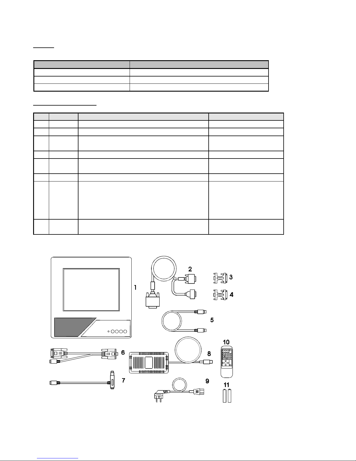
SYSTEM STRUCTURE
The display system consists of the following main elements :
PART # ITEM DESCRIPTION
1 201.154 LCD PANEL, POLAVIEW HR 2500 Display unit
2 301.075 CABLE VGA Analogue computer cable
3 301.133 CABLE-ADAPTER MAC MON. MAC monitor adapter
4 301.126 ADAPTER MAC-UNIVERSAL MAC-Universal adapter
5 301.102 MOUSE CABLE Base 4m mouse cable
6 301.103 MOUSE ADAPTER PC Y-SPLIT PC mouse adapter
7 301.105 MOUSE ADAPTER MAC Mac ADB mouse adapter
8 300.061 POWER -5, 12, 5 V UP-043 Power supply unit
9 300.065 POWER CORD EUR European power cord
300.066 POWER CORD GB UK power cord
* 300.067 POWER CORD US US power cord
* 300.068 POWER CORD AUS Australian power cord
300.069 POWER CORD ITA Italian power cord
10 402.063 REMOTE CONTROL, POLAVIEW HR 2500 Infrared remote control
* Accessories not included in regular Polaview HR 2500 delivery (Country/Language dependent)
For a complete overview of parts & accessories available, see the Addendum (SPPL).
3
 Loading...