

Page 1
Repair Manual
Americas Business Center
Technical Services
201 Burlington Road
Bedford MA 01730
TEL: 1.781.386.5309
FAX: 1.781.386.5988
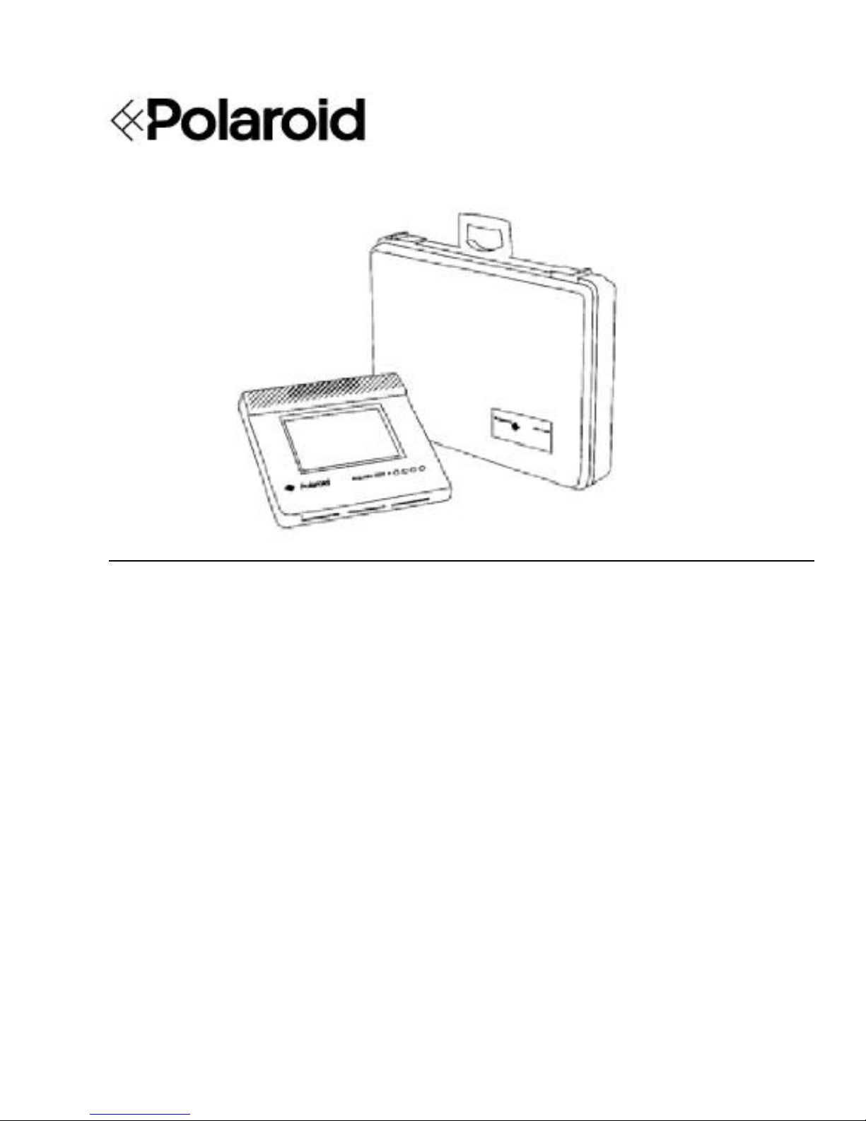
Polaview 3000 LCD Panel
September 1996
Page 2
BOARD LEVEL POLAVIEW 3000
SERVICE MANUAL
SCOPE
This document describes the assembly of the POLAVIEW 3000 board level elements.
The manual serves as a guide for the replacement of such elements when the unit needs servicing. Board level repair
may only be performed by the company :
COMPANY
REFERENCE
as authorized by ASK. Any unauthorized repair that is performed outside the scope of this document will violate any
warranties and could potentially damage the unit.
The document does not assist in repairing the elements themselves (such as replacing individual components on the
electronic circuit boards).
This Board Level Service manual is accompanied by the SPAREPART PRICE LIST document which outlines order
procedures for replacement parts, warranty details, returns and payment terms etc.
REVISION HISTORY
01.03.94 JE Draft based on Service Manual Impact 21
01.03.94 HM Upgraded to Polaview 3000
16.05.94 HM Released
12.09.94 HM Updated tables and drawings
TABLE OF CONTENTS
SCOPE........................................................................................................................................................................ 2
REVISION HISTORY................................................................................................................................................ 2
TABLE OF CONTENTS ............................................................................................................................................ 2
TOOLS ....................................................................................................................................................................... 4
SYSTEM STRUCTURE ................................ ............................................................................................................ 4
REPLACING SYSTEMS ELEMENTS ...................................................................................................................... 4
DISPLAY UNIT STRUCTURE ................................................................................................................................. 5
SERVICING THE DISPLAY UNIT ................................ ........................................................................................... 6
Opening the unit [15 min] ............................................................................................................................. 6
Replacing the controller card [15 min] ..........................................................................................................6
Replacing the LCD module [15 min] ............................................................................................................ 6
Replacing the LCD module harness [15 min] ................................ ............................................................... 6
Replacing the keyboard [15 min] .................................................................................................................. 6
Replacing the fan [15 min] ............................................................................................................................ 7
Replacing the upper protection glass [15 min] .............................................................................................. 7
Replacing the lower protection glass [15 min] .............................................................................................. 7
Replacing the housing top [30 min] .............................................................................................................. 7
Replacing the housing bottom [30 min] ........................................................................................................7
Replacing the speaker [15 min] ..................................................................................................................... 7
2
Page 3

BOARD LEVEL POLAVIEW 3000
SERVICE MANUAL
3
Page 4

BOARD LEVEL POLAVIEW 3000
PART # ITEM DESCRIPTION
SERVICE MANUAL
TOOLS
You need a the following tools for board level repair :
TOOL USE
Pozidrive no.2 screwdriver Opening housing, replacing elements
5 mm nutdriver Fastening the COMPUTER connector
8 mm open-end wrench Replacing cooling fan
SYSTEM STRUCTURE
The display system consists of the following main elements :
1 201.114 LCD PANEL, POLAVIEW 3000 Display unit
2 301.107 AV CABLE Audio-Video cable
3 301.075 CABLE VGA Analogue computer cable
4 301.077 CABLE-ADAPTER MACII MON. MACII monitor adapter
5 301.076 CABLE-ADAPTER MACII COMP. MACII computer adapter
* 301.128 CABLE-ADAPTER CGA/EGA MON. CGA/EGA monitor adapter
* 301.129 CABLE-ADAPTER CGA/EGA COMP. CGA/EGA computer adapter
6 301.102 MOUSE CABLE Base 4m mouse cable
7 301.103 MOUSE ADAPTER PC PC mouse adapter
8 301.105 MOUSE ADAPTER MAC Mac ADB mouse adapter
9 300.061 POWER -5, 12, 5 V Power supply unit
10 300.065 POWER CORD EUR European power cord
11 402.094 REMOTE CONTROL, POLAVIEW 3000 Infrared remote control
12 408.000 BATTERY 2 x LR03 2 Pcs. AAA Batteries
* Accessories not included in regular POLAVIEW 3000 delivery (Cuuntry/Language dependant)
For a complete overview of parts & accessories availabel, see the Addendum (SPPL).
REPLACING SYSTEMS ELEMENTS
4
Page 5

BOARD LEVEL POLAVIEW 3000
SERVICE MANUAL
All system elements as described above are replaceable in the field. The repair of the display unit at the board level is
described below. The other elements (such as electronics) are not serviceable and should therefore be replaced if they
fail.
DISPLAY UNIT STRUCTURE
The display unit consists of the following board level elements :
PART # ITEM DESCRIPTION
1 402.131 CABINET TOP, POLAVIEW 3000 Housing top, complete
2 400.130 GLASS Protection glass
3 400.126 MASK Rubber mask
4 300.025 SHARP LQ9P011/12/14 LCD module
5 509.015 FERRITE Radio noise filter
6 301.095 LCD CABLE Internal LCD module cable
7 400.045 PANASONIC FAN Cooling fan
8 402.130 CABINET BOTTOM, POLAVIEW 3000 Housing bottom, complete
9 400.130 GLASS Protection glass
10 506.243 KEYS (x4) Silicone rubber keys
11 308.048 KEYBOARD Front panel circuit board
12 301.096 KEYBOARD CABLE Keyboard cable
13 301.073 SPEAKER WITH CABLE Internal speaker
14 402.132 BRACKET, POLAVIEW 3000 Connector Panel and Decal
15 308.050 CONTROLLER, I24 Controller board
See the attached exploded drawing of the board level elements on page 7.
Additionally available is a kit of mounting details (screws, washers etc) :
POS PART# ITEM DESCRIPTION
402.502 MOUNTING KIT Kit of mounting details
5
Page 6

BOARD LEVEL POLAVIEW 3000
SERVICE MANUAL
SERVICING THE DISPLAY UNIT
All maintenance of the unit shall be performed at a static-free workstation. Work in a dust free environment if possible,
and have access to a high pressure air blower to remove dust when assembling the unit.
The unit must be disconnected from the power supply and computer before opening.
Nominal time needed to perform each operation is shown in square brackets [ ].
Opening the unit [15 min]
Place the display facing down on a scratch-free surface. Remove the four mounting screws. Gently open the housing,
observing the cables that connect the elements in the top and bottom parts.
Replacing the controller card [15 min]
Disconnect the LCD cable (6) from the controller board (15), and the fan (7) from the controller board (15). Unscrew
the three mounting screws of the board and the two screws holding the computer connector (14).
Replace with a new card, reversing the above procedure.
Replacing the LCD module [15 min]
Disconnect the LCD cable (6) from the LCD module (4). Unscrew the four mounting screws. Gently lift off the
module. Beware that the top glass is held in place by the module.
If the LCD module is broken, soak up any spilled liquid and dispose of in ordinary litter. Use gloves. Wrap broken
glass thoroughly and wash your hands.
Replace the LCD module. Take care to remove any dust between the LCD module and the glass before reassembling.
Replacing the LCD module harness [15 min]
Disconnect the cable (6) from the LCD module (4) and the controller board (15).
Replace with a new cable, observing the correct polarity at both ends. At the controller board end, the cable will have
either a notch for polarization, or an arrow mark at pin 1.
Replacing the keyboard [15 min]
The keyboard (11) is mounted in the housing top. A circuit board holds four separate silicone rubber keys (10) in
place.
Disconnect the keyboard cable (12) from the keyboard (11). Unscrew the screws holding the circuit board. Carefully
lift off the board. Replace the rubber keys (10) and/or the circuit board as needed. Check key operation after
reassembling for smooth operation.
6
Page 7

BOARD LEVEL POLAVIEW 3000
SERVICE MANUAL
Replacing the fan [15 min]
The fan (7) is mounted on the housing bottom by four nuts. Disconnect the fan cable from the controller board (15)
and remove the four nuts.
Replace with a new fan.
Replacing the upper protection glass [15 min]
To replace the upper protection glass (2), follow the above procedure on replacing the LCD module. If the glass is
broken, observe the surface of the LCD module for scratches that may affect the display quality and replace the LCD
module if necessary. Wrap broken glass thoroughly.
Replace with a new glass, reversing the above procedure.
Replacing the lower protection glass [15 min]
This glass (9) is removed from the outside, without opening the display unit, and may be performed by the user. The
glass is held in place by springs. Use two fingers to slide the glass out and replace with a new glass. Refer to the
instructions in the User Guide.
Check that the new glass is correctly ground on the edges to avoid cutting wounds.
Replacing the housing top [30 min]
Remove the LCD module (4) and upper glass (2) as described previously under LCD module replacement.
Also remove the keyboard (11) and cable (12).
Replace with a new housing top, reversing the above procedure.
Replacing the housing bottom [30 min]
Remove the controller board (15) and fan (7) as described previously.
Replace with a new bottom part.
Replacing the speaker [15 min]
Unplug the speaker cable (13) from the controller board (15). Unscrew the four nuts holding the speaker (13)
Replace with a new speaker.
7
Page 8

BOARD LEVEL POLAVIEW 3000
SERVICE MANUAL
8
 Loading...