

Page 1

50” Plasma Monitor PLA-5040
50” Plasma Monitor
PLA-5040
20050825
Page 2

Table of Contents
Important Information..................................................................................................1
Important SafetyPrecautions......................................................................................2
Preparations................................................................................................................5
Identification of Controls..............................................................................................7
Connections..............................................................................................................10
Turningthe Unit On and Off......................................................................................16
Basic Operations.......................................................................................................17
Setting Picture...........................................................................................................18
Changing Screen Options.........................................................................................19
Setting Sound ...........................................................................................................21
Setting System..........................................................................................................23
Changing Screen Layout ..........................................................................................24
PIP Operations..........................................................................................................25
Viewing Closed Captions..........................................................................................26
Adjusting Parental Control Settings..........................................................................27
Troubleshooting........................................................................................................31
Specifications............................................................................................................32
Programming the Universal Remote Control............................................................34
Page 3
Important Information
WARNING:
CAUTION-To reduce the risk of electric shock, do not perform any
Thisproductutilizestin-leadsolder,andfluorescentlampcontainingasmallamountofmercury.Disposalofthesematerialsmayberegulateddue
toenvironmentalconsiderations. For disposal or recyclinginformation,please contact your local authoritiesorthe Electronic IndustriesAlliance:
www.eia.org
TO REDUCE THE RISK OF FIRE OR ELECTRIC SHOCK, DO NOT EXPOSE THIS APPARATUS TO RAIN OR
MOISTURE.
The lightning flash with arrowhead symbol,
CAUTION
RISK OF ELECTRIC SHOCK
DO NOT OPEN
servicing other than that contained in the operating
instructionsunlessyouarequalifiedtodoso.
within an equilateral triangle is intended to
alert the user to the presence of uninsulated
dangerous voltage within the product's
enclosure that may be of sufficient magnitude to
constituteariskofelectricshocktopersons
The exclamation point within an equilateral
triangle is intended to alert the user to the
presence of important operating and
maintenance (servicing) instructions in the
literatureaccompanyingtheappliance.
.
FCC STATEMENT
FCC Notice
PDP Monitor: ACLASS B digital device
ThisequipmenthasbeentestedandfoundtocomplywiththelimitsforaClassBdigitaldevice,pursuanttopart15oftheFCCRules.These
limits are designed to provide reasonable protection against harmful interference when the equipment is operated in a commercial
environment.
Thisequipment generates, uses, and canradiate radiofrequency energy and, if notinstalled andused in accordancewith theinstruction
manual, may cause harmful interference to radio communications. Operation of this equipment in a residential area is likely to cause
harmfulinterferenceinwhichcasetheuserwillberequiredtocorrecttheinterferenceathisownexpense.
FCC CAUTION:
Pursuant to 47CFR, Part 15.21 of the FCC rules, any changes or modifications to this monitor not expressly approved by the
manufacturercouldcauseharmfulinterferenceandwouldvoidtheuser'sauthorityto operatethisdevice.
WARNING:This isa CLASS B product. In adomestic environment this product may causeradio interference in
whichcasetheusermayberequiredtotakeadequatemeasurestocounterinterference.
1
Page 4
Important Safety Precautions
Electrical energy can perform many useful functions, but it can also cause personal injuries and property damage if improperly handled.
This product has been engineered and manufactured with the highest priority on safety. But IMPROPER USE CAN RESULT IN
POTENTIAL ELECTRICAL SHOCK OR FIRE HAZARD. In order to prevent potential danger, please observe the following instructions
wheninstalling, operating andcleaningtheproduct.Toensureyoursafetyand prolong theservicelifeofyourPDPmonitorproduct, please
readthefollowingprecautionscarefullybeforeusingtheproduct.
1.Readtheseinstructions---Alloperatinginstructionsmustbereadandunderstoodbeforetheproductisoperated.
2.Keeptheseinstructions---Thesesafetyandoperatinginstructionsmustbekeptinasafeplaceforfuturereference.
3.Heedallwarnings---Allwarningsontheproductandintheinstructionsmustbeobservedclosely.
4.Followallinstructions---Alloperatinginstructionsmustbefollowed.
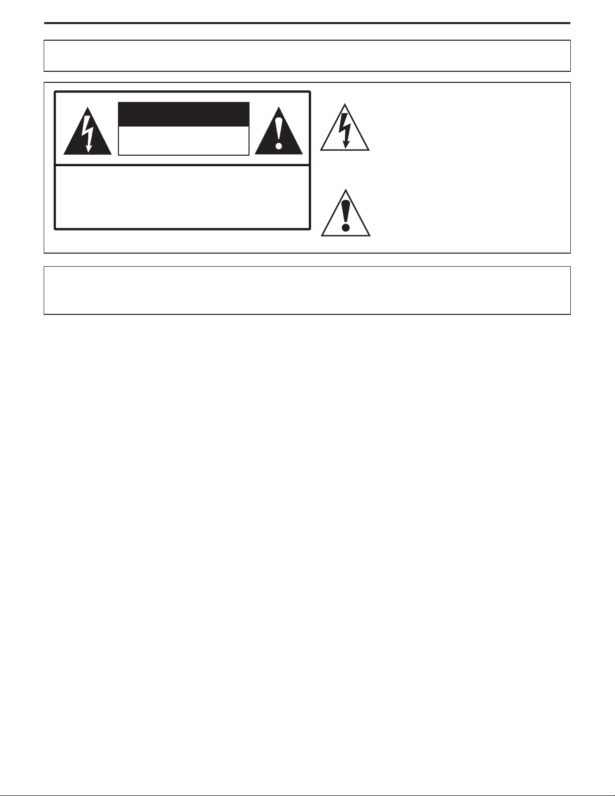
5. Do not use this apparatus near water---for example, near a bathtub, washbowl,
kitchensink,orlaundrytub,inawetbasement,ornearaswimmingpool,andthelike.
Do not use immediately after moving from a low temperature to high temperature
environment, as this causes condensation, which may result in fire, electric shock, or
otherhazards.
6. Clean onlywith dry cloth---Unplug this product from the wall outletbefore cleaning.
Donotuseliquidcleanersoraerosolcleaners.Useadampclothforcleaning.
Ventilation---
7. Do not block any ventilation openings. Install in accordance with the
manufacturerinstructions.The vents andother openings inthe cabinet aredesigned for
ventilation.Do notcover orblock thesevents andopenings sinceinsufficient ventilation
cancauseoverheatingand/orshortenthelifeoftheproduct.Donotplacetheproduct on
abed, sofa, rug or othersimilar surface, since they canblock ventilation openings. This
product is not designed for built-in installation; do not place the product in an enclosed
place such as a bookcase or rack, unless proper ventilation is provided or the
manufacturer’sinstructionsarefollowed.
8.Heatsources---Donotinstallnear any heat sourcessuchasradiators,heatregisters,
stoves,orotherapparatus(includingamplifiers)thatproduceheat.
9.GroundingorPolarization---Donot defeat the safetypurposeofthe polarized or grounding-typeplug.Apolarizedplughas two blades
with one wider than the other.Agrounding type plug has two blades and a third grounding prong. The wide blade or the third prong are
providedforyoursafety.Iftheprovidedplugdoesnotfitintoyouroutlet,consultanelectricianforreplacementoftheobsoleteoutlet.
10.Powercordprotection---Protectthe power cordfrombeingwalked on orpinchedparticularlyat plugs, conveniencereceptacles,and
thepointwheretheyexitfromtheapparatus.
11. Only use attachments/accessories specified by the manufacturer. Do not use attachments not recommended by the
Attachments---
manufacturer.Useofimproperattachmentscanresultinaccidents.
2
Page 5
Important Safety Precautions (continued)
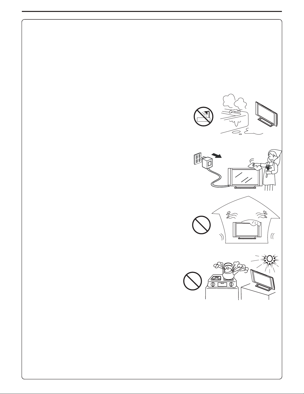
12.Stand Useonly with thecart,stand,tripod,bracket,ortablespecifiedbythe manufacturer,or
sold with the apparatus. Do not place the product on an unstable trolley, stand, tripod or table.
Placingtheproductonanunstablebasecancause the product to fall,resultinginseriouspersonal
injuriesas well as damage tothe product.When mounting the product ona wall,be sure tofollow
the manufacturer’s instructions. Use only the mounting hardware recommended by the
manufacturer.
13. When a cart is used, use caution when moving the cart/apparatus
combinationtoavoidinjuryfromtip-over.Suddenstops,excessiveforceandunevenfloorsurfaces
cancausetheproducttofallfromthetrolley.
14.Lightning---Unplug this apparatus during lightningstorms orwhen unused for long periodsof
time.
For added protection for this television equipment during a lightning storm, or when it is left
unattended and unused for long periods of time, unplug it from the wall outlet and disconnect the
antenna.Thiswillpreventdamagetotheequipmentduetolightningandpower-linesurges.
---
Move carefully---
15.Servicing---Refer all servicingtoqualifiedservicepersonnel.Servicingisrequiredwhen the apparatushasbeendamagedinanyway,
suchas power-supplycord orplug is damaged, liquid has been spilled or objects have fallen into the apparatus, the apparatus hasbeen
exposedtorainormoisture,doesnotoperatenormally,orhasbeendropped.
16. Replacement parts---In case the product needs replacement parts, make sure that the service person uses
replacement parts specified by the manufacturer, or those with the same characteristics and performance as the
originalparts.Useofunauthorizedpartscanresultinfire,electricshockand/orotherdanger.
17.Overloading---Do not overload wall outlets, extension cords, or convenience receptacles on other
equipmentasthiscanresultinariskoffireorelectricshock.
18.Enteringofobjects and liquids---Never insert an object into the product through vents or openings.Highvoltageflowsintheproduct,
andinsertinganobjectcancauseelectricshockand/orshortinternalparts.Forthesamereason,donotspillwaterorliquidontheproduct.
19.Damagerequiringservice---Ifanyofthefollowingconditionsoccurs,unplugthepowercordfromtheACoutlet,andrequestaqualified
servicepersontoperformrepairs.
a.Whenthepowercordorplugisdamaged.
b.Whenaliquidisspilledontheproductorwhenobjectshavefallenintotheproduct.
c.Whentheproducthasbeenexposedtorainorwater.
d.Whentheproductdoesnotoperateproperlyasdescribedintheoperatinginstructions.
Do not touch the controls other than those described in the operating instructions. Improper adjustment of controls not described in the
instructionscancausedamage,whichoftenrequiresextensiveadjustmentworkbyaqualifiedtechnician.
e.Iftheproducthasbeendroppedorthecabinethasbeendamagedinanyway.
f.When theproductdisplaysanabnormalconditionorexhibitsadistinct change inperformance.Any noticeableabnormalityintheproduct
indicatesthattheproductneedsservicing.
20.Safety checks---Upon completion of service or repair work, request the service technician to perform safety
checkstoensurethattheproductisinproperoperatingcondition.
21.Wall or ceiling mounting---When mounting the product on a wall or ceiling, be sure to install the product according to the method
recommendedbythemanufacturer.Thisisasafetyfeature.
3
Page 6
Important Safety Precautions (continued)
22.Powersource---Thisproductisintendedtobesuppliedbyalistedpowersupplyindicatedonthemarkinglabel.Ifyouarenotsureofthe
type of power supply to your home, consult your product dealer or local power company.For added protection for this product during a
lightning storm, or when it is left unattended and unused for long periods of time, unplug it from the wall outlet and disconnect the cable
system.Thiswill prevent damageto the productdue to lightningand powerlinesurges. Whenthe unit hasto be usedwith another power
supplyvoltage, the powercable must bechanged. Consultyour product dealer.The socket outletshould beinstalled near theequipment
andeasily accessible.Useonlythepowercorddesignatedbyour dealertoensuresafetyandEMC.Whenconnecting other productssuch
asVCRsandpersonalcomputers,youshouldturnoffthepoweroftheunitforprotectionagainstelectricshock.
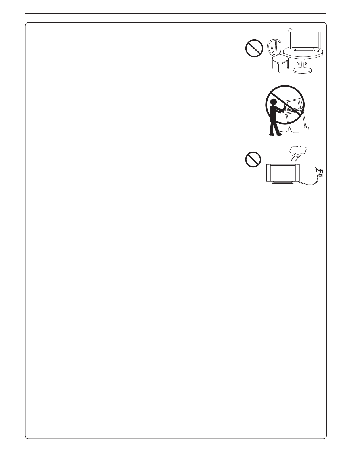
23.Panelprotection---ThePDPpanelusedinthisproductismadeofglass.Therefore,itcanbreak
when the product is dropped or impacted upon by other objects. Be careful not to be injured by
brokenglasspiecesincasethePDPpanelbreaks.
24.Pixel defect---The PDP panel is a very high technology product, giving you finely detailed pictures. Occasionally, a few non-active
pixelsmayappearonthescreenasafixedpointofblue,greenorred.Pleasenotethatthisdoesnotaffecttheperformanceofyourproduct.
4
Page 7
Preparations
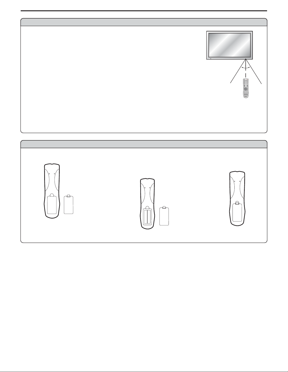
Using the Remote Control
<Usetheremotecontrolbypointingittowardstheremotesensorwindowoftheset.Objectsbetween
theremotecontrolandsensorwindowmaypreventproperoperation.
Note: This illustration is for reference only. The remote sensor may be in different locations on
different models.
30
30
5m
Cautions regarding use of remote control
<Donotexposetheremote control toshock.Inaddition,do not expose theremotecontrolto liquids,
anddonotplaceinanareawithhighhumidity.
<Donotinstallorplacetheremotecontrolunderdirectsunlight.Theheatmaycausedeformationoftheunit.
<Theremotecontrolmaynotworkproperlyiftheremotesensorwindowofthemainunitisunderdirectsunlightorstronglighting.Insucha
case,changetheangleofthelightingorPDPmonitorset,oroperatetheremotecontrolclosertotheremotesensorwindow.
Batteries for the Remote Control
Openthebatterycover.
1
Precaution on battery use
Improperuseofbatteriescanresultinaleakageofchemicalsand/orexplosion.Besuretofollowtheinstructionsbelow.
<
Placebatterieswiththeirterminalscorrespondingtothe(+)and(–)indications.
<
Differenttypesofbatterieshavedifferentcharacteristics.Donotmixbatteriesofdifferenttypes.
<
Do not mix old and new batteries.Mixing old andnew batteries canshorten the lifeof new batteriesand/or cause old batteries to leak
chemicals.
<
Removebatteriesassoonas they are non-operable.Chemicalsthatleakfrom batteries can causearash.Ifchemical leakage isfound,
wipewithacloth.
<
Thebatteriessuppliedwiththeproductmayhaveashorterlifeexpectancyduetostorageconditions.
<
Iftheremotecontrolisnotusedforanextendedperiodoftime,removethebatteriesfromtheremotecontrol.
Inserttwosize-AAbatteries.
2
<(Place the batteries with their terminals
correspondingto the(+) and(–) indications
inthebatterycompartment.)
+
-
+
-
Replacethecover.
3
5
Page 8
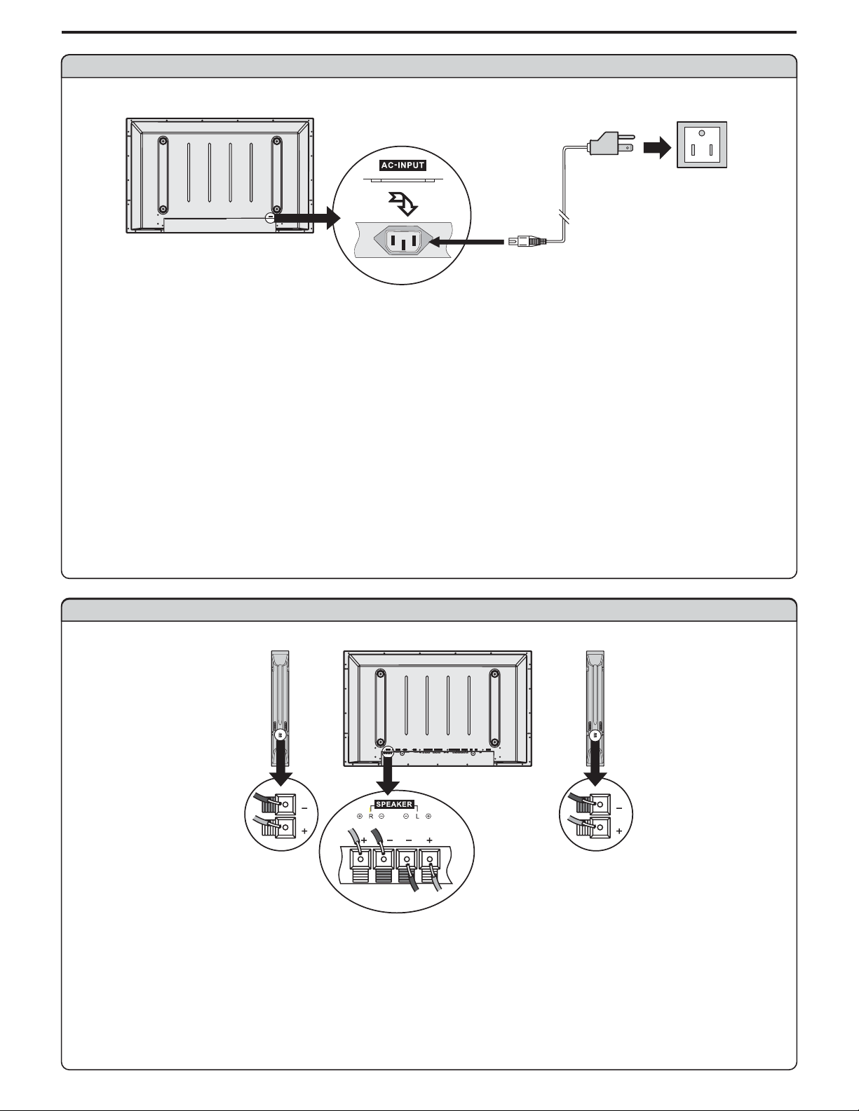
Power connection
AC cord
AC-INPUT
1.ConnectingthefemaleplugtotheACsocketontheunit.
2.Connectingthemaleplugtothewalloutletasillustrated.
Note:
<
This product shouldbeoperated only fromthe type ofpowersource indicated onthe marking label.
<
Always unplug theAC cord frompower outlet whennot using for along period oftime.
Preparations (continued)
Household
power outlet
Plug into AC outlet.
Speaker connection
(Black)
(Red)
Right
speaker
Note: the illustrationmay be different dependingonmodel.
SPEAKER DVI AVOUTPUT
CONTROL
COMPONENTINPUT1 COMPONENTINPUT2D-SUB
C/P
C/P
L
R
Y
AUDIO
C/PbbC/P
AUDIO
PIC
Y
PIC
AUDIO
AUDIO
rr
rr
bb
Left
speaker
AVINPUT
HEADPHONE
AC-INPUT
SVHS
RF
RLAUDIO RLAUDIO
VIDEO VIDEO
(Black)
(Red)
Connect the speaker audio cable to
the external speaker output jack on
theunit matchingthe "+"and"-" ends
ofthecablewithcolor.
6
Page 9
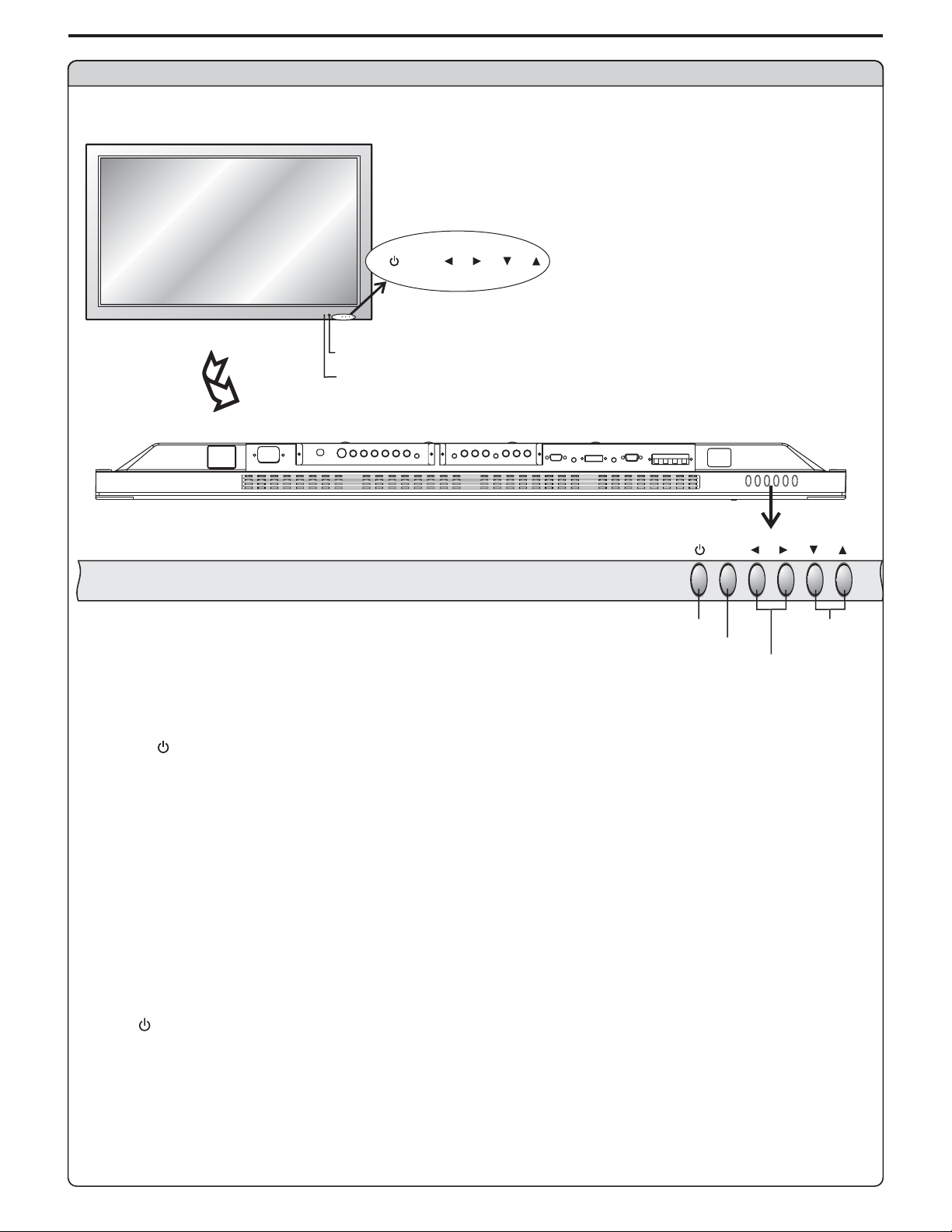
Identification of Controls
Main unit (front view)
MENU
VOL
MENU
SOURCE
VOL
REMOTE SENSOR
POWER INDICATOR
Ablue indicator lights when the power is on and a red
indicator lights when in the standby mode.
BOTTOM VIEW
POWER ON/STANDBY
VOLUME DOWN/UP
1. POWER
Press this button to turn the unit ON from STANDBYmode. Press it again to turn the set back to STANDBY.
2. MENU
Press this button to access the MENU main page.
3. Volume /
Press the VOL or VOL button to directly increase or decrease the sound volume level.
34
43
In OSD Menu, press these buttons to adjust the value or setting of each item
4. /
56
In OSD Menu, press these buttons to choose the OSD items.
MENU
MENU
VOL
DOWN/UP
Note:
POWER VOL / / MENU, , and on the main unit have the same functions as the corresponding buttons on the remote
34 56
control.
This operation manualprovidesa description basedon operating functionswiththe remote control.
7
Page 10
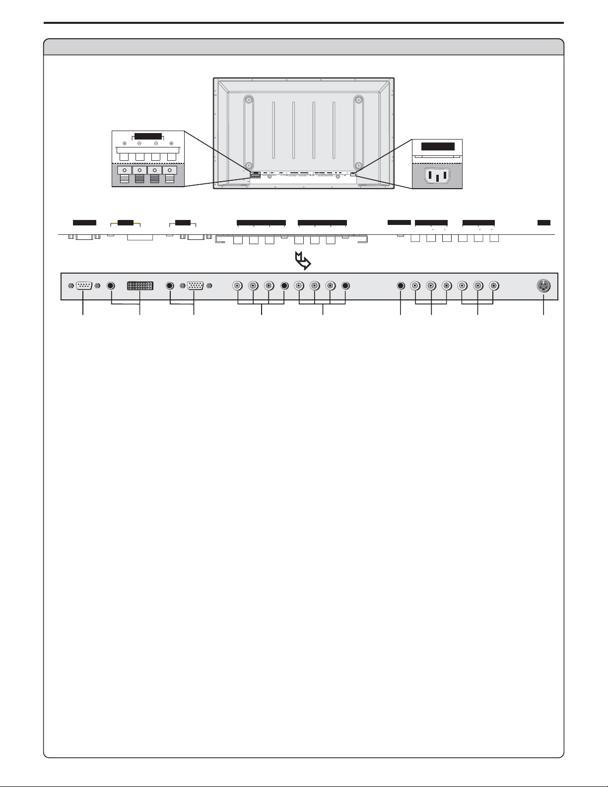
Main unit (rear view)
Identification of Controls (continued)
Speaker output jacks
SPEAKER
L
DVI AVOUTPUT
CONTROL
C/P
COMPONENTINPUT1 COMPONENTINPUT2D-SUB
C/P
AUDIO
C/PbbC/P
PIC
Y
PICAUDIO
AUDIO
rr
AUDIO
rr
SPEAKER
L
R
D-SUB
AUDIO
PICAUDIO
PIC
COMPONENT INPUT 1 COMPONENT INPUT 2D-SUB
C/P
Y
bb
AVINPUT
HEADPHONE
SVHS
RF
C/P
Y
AUDIO
VIDEO VIDEO
rr
bb
Y
C/P
bb
AC-INPUT
RLAUDIO RLAUDIO
C/P
AUDIO
rr
CONTROL
R
DVI AV O UTP UT
BOTTOM VIEW
1
2
3
4
5
1. RS232 terminals
For service use only.The user cannot operate the unit through the RS232 terminals.
2. DVI input /Audio in
Receives the digital video/audio signals from a set top box or PC.
3. VGA input /Audio in
Connect to the VGA/audio output jacks on your PC.
4. Component inputs 1
(Y, Pb/Cb, Pr/Cr,Audio)
Connect to the audio and component output jacks of a DVD player or Set-Top Box.
5.
Component inputs 2 (Y, Pb/Cb, Pr/Cr,Audio)
Connect to the audio and component output jacks of a DVD player or Set-Top Box.
6. Headphone jack
(
7.AV outputs
Video,Audio L, R)
Connect to the VCR input jacks to record programs.
8.AV inputs
(Video,Audio L, R)
Receive video/audio signals from external sources such as VCR or DVD player.
9. S-Video input
Receive a S-Video signal from external source such as VCR or DVD player.
AC power
input socket
HEADPHONE
VIDEO VIDEO
6
AC-INPUT
7
AV I NPU T
RL AUDIO RL AUDIO
8
SVHS
9
8
Page 11
Identification of Controls (continued)
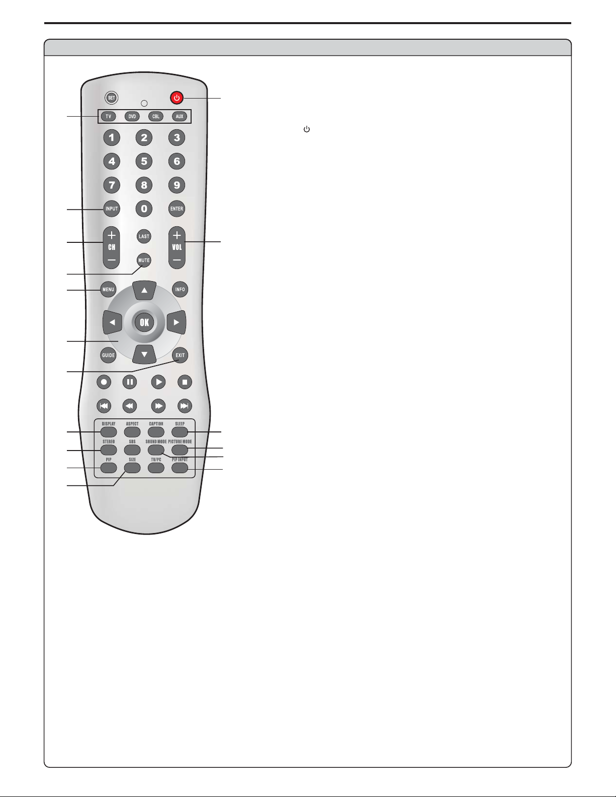
Remote Control
1 Toselectproductstobecontrolledwithremotecontrol
.
Note: universal
controldoes not workcorrectly when youoperate the PDPmonitor,please
trytopress button.
2 POWER
.
Turnthe unit on or off
3 INPUT
.
To access source input select menu
4. CH+/-
To move upward or downward in menu operation
5. VOL+
Used to adjust volume.
To move left or right in menu operation;
To adjust selected menu item in menu operation;
.
6 MUTE
Sound mute
7 MENU
.
To access the Menu main page or exit menu operation
8 Menu navigation button:
.
9. EXIT
Used to exit the current menu and return to upper level menu.
10. DISPLAY
To display channel status or signal information
11.SLEEP
To access Sleep timer setting menu
12. STEREO
To select STEREO, SAP or MONO
13.
To access picture mode select menu
14.
To access sound mode select menu
15. PIP
To
16.
To access source input select menu
17 SIZE
.
To access PIP frame size adjusting menu
1
3
4
6
7
8
9
10 11
12
15
17
13
14
16
2
5
This remote control is an remote control. If your remote
TV
/-
5634
: Tomove upward or downward in menu operation;
56
To adjust zoom rate in ZOOM mode and pan picture in PAN
mode;
To select picture frame in multi-picture mode, the selected
picture frame displays with a green border;
: Tomove left or right in menu operation;
34
To adjust selected menu item in menu operation;
To pan picture in PANmode;
OK button
PICTURE MODE
SOUND MODE
activate picture in picture
PIP INPUT
To confirm, enter submenu or toggle between the settings
:
of the selected menu item.
9
Page 12
Connections
Cautions before connecting
Carefullychecktheterminalsforpositionandtypebeforemakinganyconnections.
Theillustrationoftheexternalequipmentmaybedifferentdependingonyourmodel.
Looseconnectorscanresultinimageorcolorproblems.Makesurethatallconnectorsaresecurelyinsertedintotheirterminals.
Refertotheusermanualoftheexternaldeviceaswell.
Whenconnectinganexternaldevice,turnthepoweroffonthepaneltoavoidanyissues.
NOTE:Due to variances in DVI with HDCP(High-bandwidthDigitalContentProtection)standardsassociatedwithcableandsatellite
boxes, Polaroid recommends using the Component Video (YPbPr) outputs from your cable/satellite box. Polaroid recommends
reservingtheDVIinputforothersourceswhichalsohaveDVIoutputs(i.e.DVDplayers,PCs).
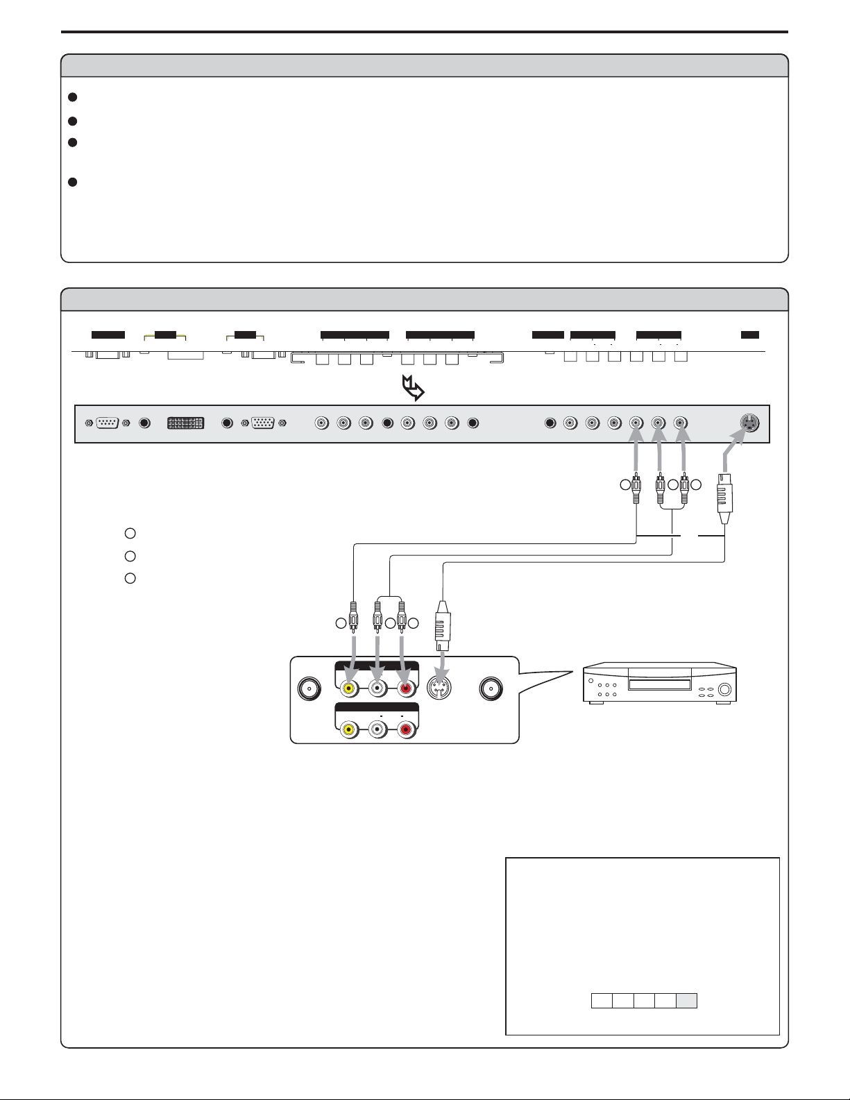
Connect a VCR
CONTROL
DVI AV O UTP UT
PICAUDIO
AUDIO
D-SUB
COMPONENT INPUT 1 COMPONENT INPUT 2D-SUB
C/P
PIC
C/P
Y
bb
AUDIO
rr
C/P
Y
C/P
AUDIO
rr
bb
HEADPHONE
BOTTOM VIEW
Y
Yellow (VIDEO)
W
White (AUDIO L)
R
Red (AUDIO R )
Video
cable
Audio
cable
AV O UT
AV I N
W
AUDIO
AUDIO
Y
S-video
cable
R
S-VIDEO
RLVIDEO
RLVIDEO
ANT INANT OUT
VIDEO VIDEO
RL AUDIO RL AUDIO
Y
AV I NPU T
VCR
SVHS
W
R
or
Rear of the VCR
How to connect:
Connect the / cablesbetween theAudio (L/R)/Video jacks on the unit and VCR.Audio Video
Note:
For better video,youcan use theS-video terminal ifyoursource supports it.
When you useS-videoterminal, the sourcemenu displays instead of .SV AV
The S-Video is priorto Video terminal whenthey are connectedatthe same time.
To play VCR
1. Turn on your PDP monitor , press button on the remote control.
2. Press to select (VIDEO) and press to confirm.
AV OK34/
3. Turn on your VCR , insert a videotape and press the Play button.
INPUT
source
A
D
C1C2
VIDEO
AV
10
Page 13
Connections (continued)
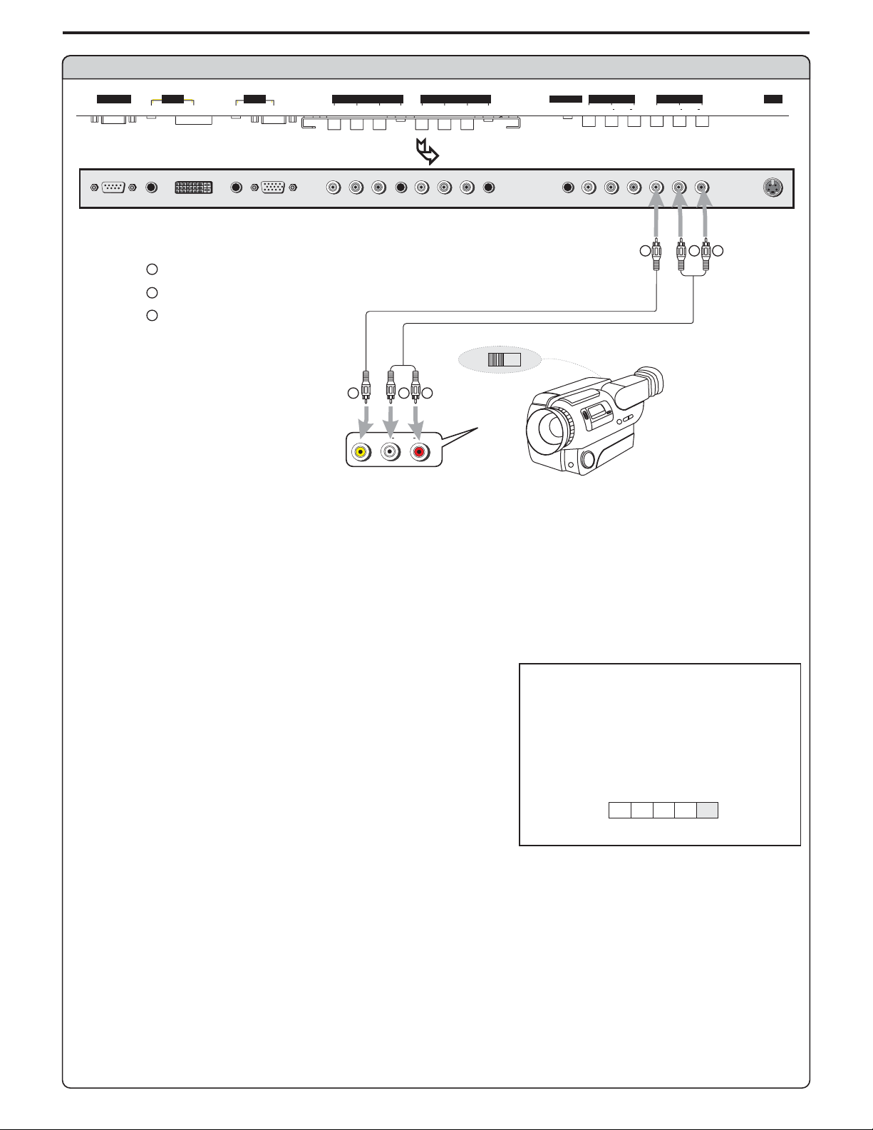
Connect a Camcorder
CONTROL
DVI AV O UTP UT
PICAUDIO
AUDIO
D-SUB
COMPONENT INPUT 1 COMPONENT INPUT 2D-SUB
C/P
PIC
C/P
Y
bb
AUDIO
rr
C/P
Y
C/P
AUDIO
rr
bb
HEADPHONE
VIDEO VIDEO
BOTTOM VIEW
Y
Yellow (VIDEO)
W
White (AUDIO L)
R
Red (AUDIO R )
Video
cable
Y
Audio
cable
W
AUDIO
OUT
R
RLVIDEO
IN
AV I NPU T
RL AUDIO RL AUDIO
Y
SVHS
W
R
How to connect:
Connect the / cablesbetween theAudio (L/R)/Video jacks on the unit and camcorder.Audio Video
To playback Camcorder
1. Turn on your PDP monitor , press button on the remote control.
2. Press to select .
AV34/ (VIDEO)and press toconfirmOK
3. Turn on your camcorder and set it to output mode. (For details, refer to your camcorder user manual.)
4. Insert the tape into the camcorder and press Play button.
Note:
The operations of the camcorder may be different and is dependant on your model.
Please read theusermanual of yourcamcorder to confirmoperation.
INPUT
source
A
D
C1C2
VIDEO
AV
11
Page 14
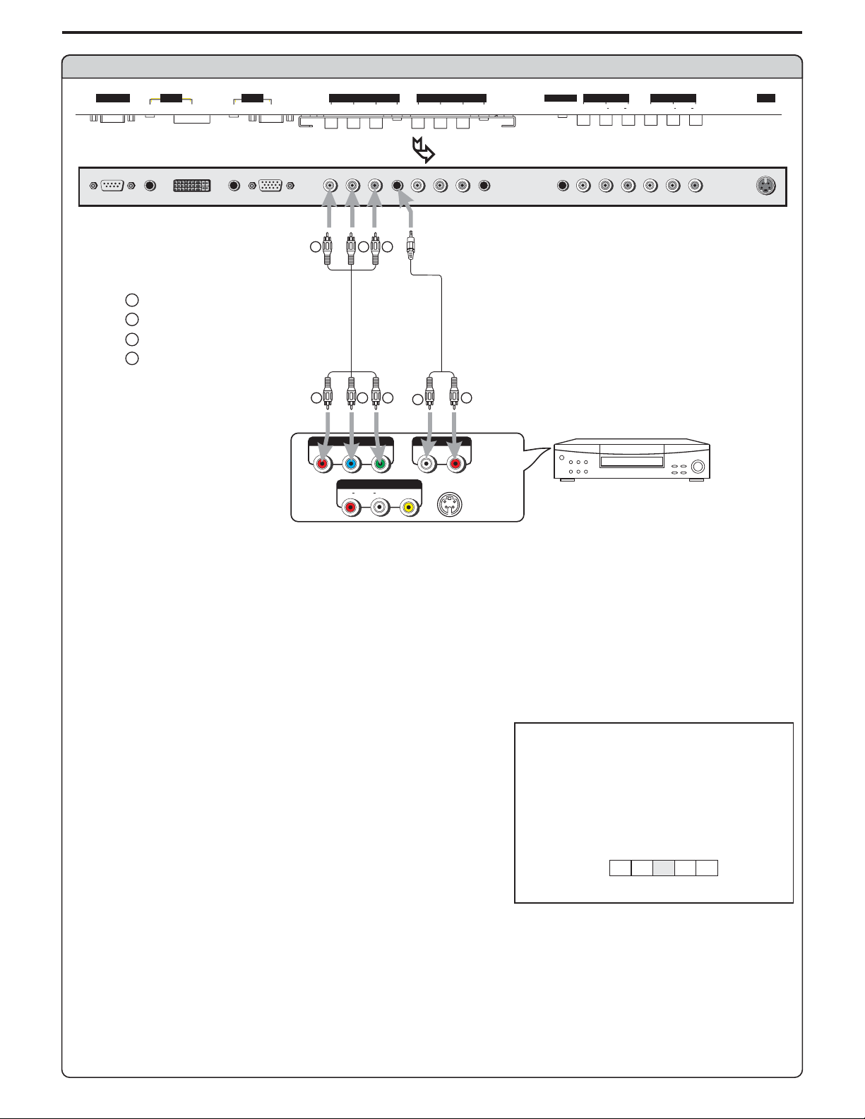
Connect a DVD player
Connections (continued)
CONTROL
DVI AV O UTP UT
PICAUDIO
AUDIO
D-SUB
COMPONENT INPUT 1 COMPONENT INPUT 2D-SUB
C/P
PIC
C/P
Y
bb
AUDIO
rr
C/P
Y
C/P
AUDIO
rr
bb
BOTTOM VIEW
RG B
W
white (audio L)
R
red (audio R, P /C )
Green (Y)
G
B
Blue (P /C )
r
r
Video
cable
b
b
R GB
P
P
r
Y
b
AV O UT
AUDIO
RLVIDEO
Audio
cable
W
AUDIOCOMPONENT
AUDIO
LR
S-VIDEO
R
HEADPHONE
VIDEO VIDEO
AV I NPU T
RL AUDIO RL AUDIO
DVD player
SVHS
Rear of the DVD player
How to connect a DVD Player using Component Video Connections:
Connect the Video cable between the Y,Cb, Cr input jacks on the unit and DVD player.
Connect the Audio cable between the AUDIO input jack on the unit and DVD player.
Y, Cb, Cr output jacks on the
AUDIO output jacks on the
To play DVD
1. Turn on your PDP monitor , press button on the remote control.INPUT
2. Press to select (YPbPr1/YCbCr1)or (YPbPr2/YCbCr2).
3. Press toconfirm.OK
4. Turn on your DVD player,insert a DVD disc and press the Play button.
Note:
This unit identifies the type of component video terminals automatically. If you connect the screen displays
detected Y,Pb,Pr
bottom-right corner.
34/ C1 C2
on the bottom-right corner. Similarly,if the component video terminalsare ,
source
A
D
C1C2
AV
YPbPr1/YCbCr1
Y, Cb, Cr
terminals,
the screen displays on the
YPbPrdetected
YCbCr
12
Page 15
Connections (continued)
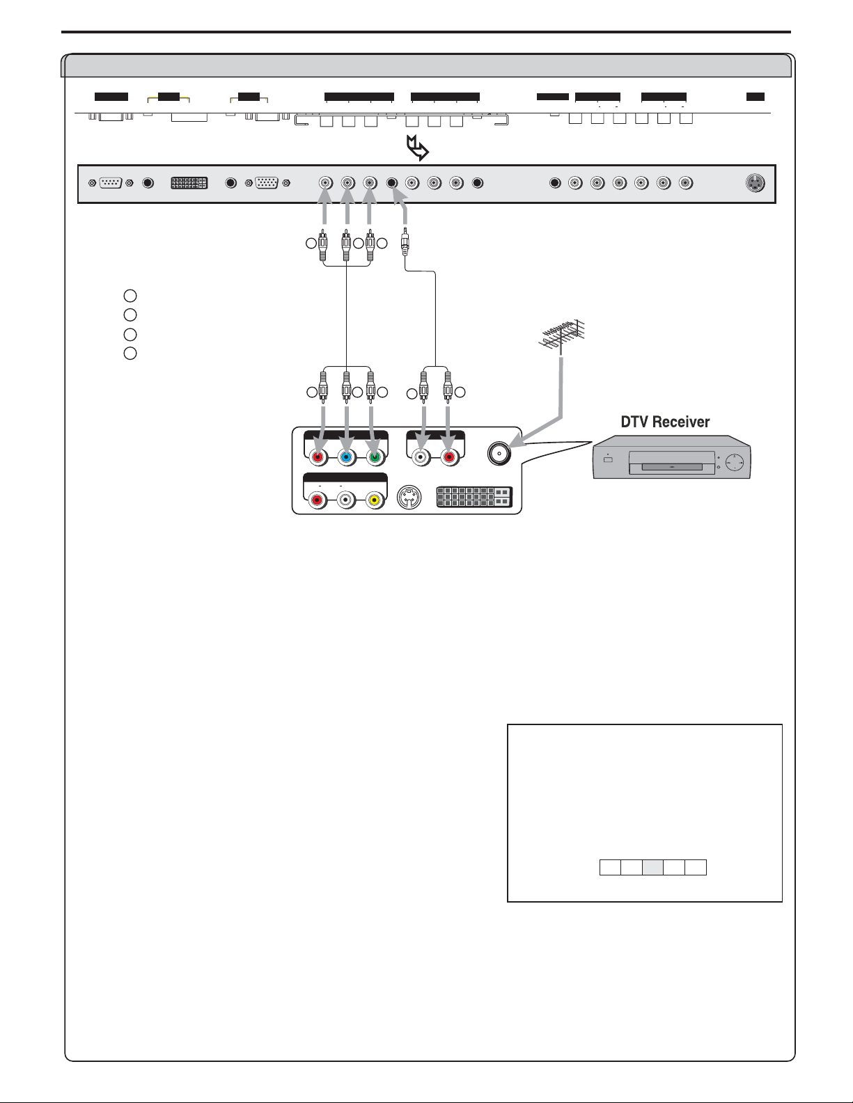
Connect a DTV receiver
CONTROL
DVI AV O UTP UT
PICAUDIO
AUDIO
D-SUB
COMPONENT INPUT 1 COMPONENT INPUT 2D-SUB
C/P
PIC
C/P
Y
bb
AUDIO
rr
C/P
Y
C/P
AUDIO
rr
bb
BOTTOM VIEW
RG B
W
white (audio L)
R
red (audio R, P /C )
Green (Y)
G
B
Blue (P /C )
rbr
Video
cable
b
R GB
P
P
r
AUDIO
RLVIDEO
b
AV O UT
Y
S-VIDEO
Audio
cable
W
AUDIOCOMPONENT
AUDIO
LR
R
ANT
DVI
HEADPHONE
VIDEO VIDEO
AV I NPU T
RL AUDIO RL AUDIO
SVHS
Rear of the DTV receiver
How to connect:
Connect the cable or antenna to the antenna input jack on the DTV receiver.
Connect the Video cable between the Y,Pb, Pr input jacks on the unit and .
Connect the Audio cable between the AUDIO input jack on the unit and .
Y, Pb, Pr output jacks on the DTV receiver
AUDIO output jacks on the DTV receiver
To Watch DTV
1. Turn on your PDP monitor , press button on the remote control.
2. Press to select (YPbPr1/YCbCr1)or (YPbPr2/YCbCr2).
3. Press toconfirm.
34/ C1 C2
OK
4. Turn on your DTV receiver.
INPUT
source
A
D
C1C2
YPbPr1/YCbCr1
AV
13
Page 16
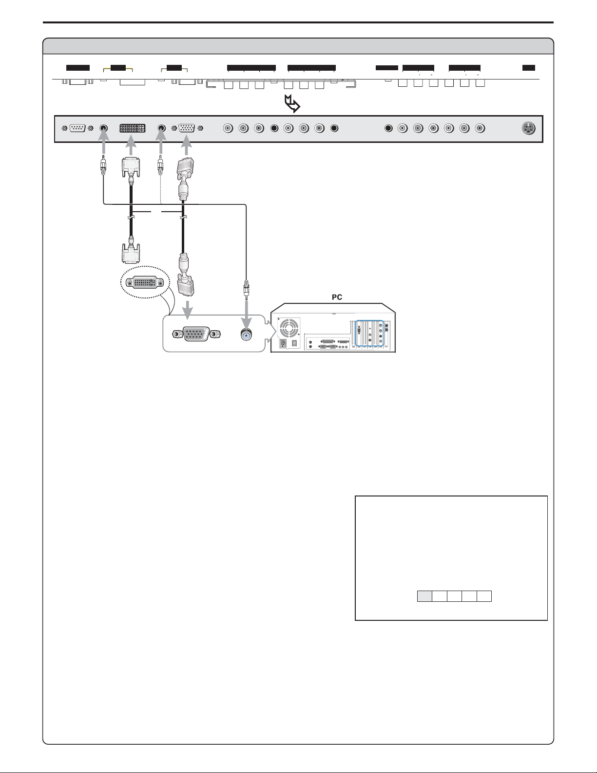
Connect a PC
Connections (continued)
CONTROL
DVI AV O UTP UT
PICAUDIO
AUDIO
D-SUB
COMPONENT INPUT 1 COMPONENT INPUT 2D-SUB
C/P
PIC
C/P
Y
bb
AUDIO
rr
C/P
Y
C/P
AUDIO
rr
bb
HEADPHONE
VIDEO VIDEO
BOTTOM VIEW
or
DVI
cable
VGA
cable
Audio
cable
AV I NPU T
RL AUDIO RL AUDIO
SVHS
How to connect:
Connect a VGA (or DVI) cable between the VGA(or DVI) jack on the PC and the VGA(or DVI) input jack on the unit.
Connect an Audio cable between the AUDIO output on the PC andAUDIO input jack on the unit.
To Watch the PC screen
1. Turn on your PDP monitor , press button on the remote control.
2. Press to select or .
3. Press to confirm.
34/ (VGA) (DVI)AD
OK
4. Turn on your PC and check for PC system requirements.
5. Adjust the PC screen.
Note:
Some playback devices with DVI interface have different understandings to the HDCP protocols and which may lead to mistakes during
transferring data stream. In this case, youmay find a noisy picture while viewingprograms from DVI interface. So if youencounter a noisy
picture, please trytorestore a normalpicture by restartingtheplayback device.
INPUT
source
A
D
C1C2
AV
VGA
14
Page 17

Connections (continued)
Connect a VCR (for recording) or external amplifier
CONTROL
DVI AV O UTP UT
PICAUDIO
AUDIO
D-SUB
COMPONENT INPUT 1 COMPONENT INPUT 2D-SUB
C/P
PIC
C/P
Y
bb
AUDIO
rr
C/P
Y
C/P
AUDIO
rr
bb
HEADPHONE
BOTTOM VIEW
Y
Yellow (VIDEO)
W
White (AUDIO L)
R
Red (AUDIO R )
Y
Audio
cable
R
W
Audio
cable
R
Video
cable
W
Y
ToAudio inputs
AV O UT
AUDIO
RLVIDEO
AV I N
AUDIO
RLVIDEO
S-VIDEO
ANT INANT OUT
VIDEO VIDEO
RL AUDIO RL AUDIO
W
R
VCR for recording
AV I NPU T
SVHS
ExternalAmplifier
Rear of the VCR
How to connect:
Connect the / cablesbetween theAudio (L/R)/Video jacks on the unit and VCR.Audio Video
- or -
Connect the Audio cables between the Audio (L/R) jacks on the unit and external amplifier.
To record program
1. Turn on your PDP monitor, select a program you wish to record.
2. Turn on your VCR, insert a videotape for recording.
3. Press the Record button to begin recording.
To enjoy high-quality sound through an external amplifier
1. Turn on your PDP monitor, select a program.
2. Turn the main volume of the amplifier to minimum.
3. Turn on the amplifier and adjust for a proper volume.
Note:
The operations of the amplifier may be different depending on model. Please read the user manual of your amplifier to confirm proper
operation.
TheAV output terminalsoutput audio/video signal inputtedfromAntenna input or AVinputs.
15
Page 18

Turning the Unit On and Off
Turningthe Unit On and Off
TurningOn
Insertthepowercordintothewalloutlet.
Pressthe buttonontheremotecontrol.
Theunitwillbeturnedonandyouwillbereadytouseit'sfeatures.
TurningOff
Withthepoweron,Pressthe buttonontheremotecontroltoturnoff.Power
Note:
You can alsouse the button ontheControl panel onthe main unit.Power
Viewing the Menus and Displays
Your PDP monitor has a simple, easy-to-use menu system that appears on the
screen.Thissystemmakesitconvenientandfasttousefeaturesontheunit.
Viewing the Menus
Power
brightness
contrast
sharpness
color
tint
picture
50
50
50
50
12
With the power on, press the buttonon the remote control. The main
1
menuappearsonthescreen.
InMENUoperations,usethe toselectmenuitem.Use toadjust
2
valueorsettingofeachitem.Use toconfirmoraccessitemsofmenu.
On-screenmenuwill disappear fromthescreen automaticallyafterabout 15
seconds,oryoucanpressthe buttonrepeatedlytoexitthemenu.
Note:
To clearly introduce the menu operations , this operation manual provides a
description based onoperation with the remotecontrol.
In MENU operations, the the
3
buttons, the buttons have the same function with the /56/
buttons;the buttonhasthesamefunctionwiththe button.
VOL+/-
ENTER OK
MENU
56/
OK
MENU
CH+/-
buttons have the same function with
34/
34
down for picture settings for current window
Displaying Status Information
Pressthe buttononthe remote control,the unit willdisplaycurrent status informationsuch as channelnumber,audio modeor
signalsource,etc.
DISPLAY
16
Page 19

Basic Operations
Adjusting the Volume
Using the volume buttons (VOL-and VOL+)
Pressthe or to or thevolume.VOL+ VOL- increase decrease
Using the Mute
Using the MUTE button
Atanytime,youcantemporarilyturnoffthesoundusingthe button.MUTE
Pressthe buttonandthesoundturnsoff.MUTE
1
Toturnmuteoff,pressthe buttonagain,orsimplypresseithertheMUTE VOL- VOL+or .
2
Select input source signal
Using the INPUT button
Pressthe buttontoaccess menu.INPUT source
11
Press or toselectadesiredinputchannel.34
2
Press toconfirmandtheunitdisplaysignalfromtheselectedinputchannel.OK
3
----------VGA,selectsignalfromVGA(15-pinD-sub)terminals.
A
----------DVI, selectsignalfromDVIterminals.
D
--------YPbPr1/ ,selectsignalfromYPbPr1/ terminals.
C1
--------YPbPr2/ ,selectsignalfromYPbPr2/ terminals.
C2
--------VIDEO (SVIDEO), select signal from S-Video or Video terminal.
AV
Note:
This unit identifies the type of component video terminals automatically. If you connect the screen displays
detected Y,Pb, Pr
bottom-right corner.
Using source select menu
Press todisplaythemenumainpage.MENU
1
Press todisplay menupage.settings/34
2
Press repeatedlytoselect item.6 sourceselect
3
Press toaccess menu.sourceselect4
4
Press or toselectadesiredinputchannel.56
5
Press to confirm and the unit displays signal from the selected input
6
channel.
The S-Video is prior to Video terminal when they are connected at the same time.
on the bottom-right corner. Similary, if the component video terminals are ,
OK
YCbCr1 YCbCr1
YCbCr2 YCbCr2
source
Y, Cb, Cr
the screen displays on the
menu background
language
close caption mode
close caption off on on mute
close capt. background
source select
AD
C1 C2
VGA
terminals,
YPbPrdetected
settings
right/left to source select
AV
opaque
English
cc1
opaque
YCbCr
17
Page 20

Customizing the Picture
Press todisplaythemenumainpage.MENU
1
If the menu does not display, press repeatedly to display
picture
Press / toselecttheitemyouwishtochange.56
2
Press toadjustthevalueoftheitem.34/
3
Press toexit.MENU
4
picture
menupage.
/34
Using the Preset Picture Mode
Press todisplay selectmenu.PICTURE picturemodeMODE
1
Press toselectadesiredpicturemode./34
2
MENU
Press toexit.
3
There are three preset picture modes ( , and ) and one
user-setpicturemode( ).
Eachpresetmodehasitsownpicturesettings.
Normal
Bright
Soft
AdjustedsettingsarestoredinUsermode.
:Selectforanormalpicture.
:Selectforabrightpicture.
:Selectforafine/softpicture.
User
Normal Bright Soft
Setting Picture
picture
brightness
contrast
sharpness
color
tint
down for picture settings for current window
Picture mode
menu to return right/left to adjust
Normal
50
50
50
50
12
Adjusting Picture in VGA Mode
Press todisplaythemenumainpage.MENU
1
If the menu does not display, press repeatedly to display
picture
picture
Press / toselect item.56 brightness contrastor
2
Press toadjustthevalueoftheitem./34
3
menupage.
34/
Adjusting the Phase and Frequency in VGA Mode
Press todisplaythemenumainpage.MENU
1
If the menu does not display, press repeatedly to display
picture
picture
Press / toselect or item.56 phase frequency
2
Press toadjustthevalueoftheitem.34/
3
Press toexit.MENU
4
menupage.
34/
brightness
contrast
phase
frequency
right/left to adjust brightness
brightness
contrast
phase
frequency
picture
50
50
50
50
picture
50
50
50
50
right/left to adjust phase
You mayfind thatimages blur,depending on theclock phaseof yourPC's Processor.Ifyou experience blurring ,
youcan obtaina clearer image by adjusting the phase setting.
Adjustthe clockfrequency of the set's internal clock signal. If shimmering or rainbow-likenoise isapparent in
theimage, tryadjusting the frequency setting.
18
Page 21

Changing Screen Options
Changing the Scaling mode of Image
Press todisplaythemenumainpage.MENU
1
Press todisplay menupage.window34/
2
Press toselect item.imagesize6
3
Press toselectaproperimagesize.34/
4
Theimagesizecanbeselectedbetween:fillall,normal,widea zoom.nd
FillAll
The Fill All mode stretches the input vertically and horizontally to fill the display from edge to edge. This mode is the default mode.
Normal
The Normal mode fills the display vertically with a 4:3 aspect picture, preserving the geometry of the input format. It performs the same
as the Fill toAspect Ratio mode..
Wide
The Wide mode only affects displays that are greater than 4:3 aspect. If the picture is less than or equal to 4:3, this mode acts as if it is
in Normal mode. It is intended to display 4:3 images on a 16:9 panel with the least picture deformity.The center of the picture is left
unstretched. The left and right sides of the picture are stretched in a non-linear fashion with the areas of greatest distortion on the
extreme left and right edges of the picture.The top and bottom five percent of the picture are cropped.
Zoom
If the display aspect ratio is greater than 4:3, this mode fills the panel horizontally, cropping 10 percent offthe top and bottom of the
picture. If the display aspect ratio is less than 4:3, this mode crops the picture by 16.5 percent on all sides and fills the panel with the
remaining picture.
image size
h position
v position
freezewindow off on
digital pan and zoom
right/left to change image size
window
fill all
50
50
Freezing the Picture
Press todisplaythemenumainpage.MENU
1
Press todisplaywindowmenupage.34/
2
Press repeatedlytoselect item.6 freezewindow
3
Press toselect oron off.34/
4
When you set this item to , the current picture will be frozen until you set
thisitemto .onoff
Note:
This menu itemappears only whenthe current screen layoutis full screen.
window
image size
h position
v position
freezewindow off on
digital pan and zoom
left/right to freeze current window
fill all
50
50
19
Page 22

Changing Screen Options (continued)
Changing the Position of the Image
Theunitallowsyoutoadjustthepositionoftheimageifitisnotwell-aligned.
Press todisplaythemenumainpage.MENU
1
Press todisplay menupage.window34/
2
Press repeatedlytoselect or item.6 hposition vposition
3
Press toadjustuntilthepictureiswell-aligned.34/
4
Using Digital Pan and Zoom
Press todisplaythemenumainpage.MENU
1
Press todisplay menupage.window34/
2
Press repeatedlytoselect item.6 digitalpanandzoom
3
Press toenter.4
4
Press / toadjustzoomratio.56
5
Note:
You can quicklyaccess Zoom menubyusing the button.ZOOM
Digital pan andzoomare not alwaysavailable.
window
image size
h position
v position
freeze window off on
digital pan and zoom
right/left to adjust h position
window
image size
h position
v position
freeze window off on
digital pan and zoom
select to activate digital zoom control
fill all
50
50
fill all
50
50
Theunitallowsyoutopanthepictureafteryouzoominthepicture
Repeatsteps1~5abovetozoominthepicture.
1
Press toaccessPanmode.OK
2
Press34 56/ or / topanthecurrentpictureintherelevantdirection.
3
Adjusting the Picture Automatically
Press todisplaythemenumainpage.MENU
1
Press todisplay menupage.window34/
2
Press repeatedlytoselect item.6 autoadjustment
3
Press tostartautoadjustment.4
4
Ifyou are not satisfied withthe picture , you mayquickly adjust the picture by
usingthe item.
After the is started, the message " appears
onthescreenandthepictureadjustmentsareautomaticallyactivated.
autoadjustment
auto adjustment Auto running
1.00
up/down to zoom
<select> for pan
menu to exit
12.34
arrow keys to pan
<select> for zoom
menu to exit
window
image size
h position
v position
freeze window off on
digital pan and zoom
auto adjustment
right/left to auto adjust
"
fill all
50
50
20
Page 23

Setting Sound
Using the Preset Audio Mode
Press todisplaythemenumainpage.MENU
1
Press todisplay menupage.audio34/
2
Press toselect item.6 Audiomode
3
Press toselectadesiredAudiomode.34/
4
Note:
You can not access the and items unless the is set totreble bass Audio mode
User.
Customizing the Sound
Press todisplaythemenumainpage.MENU
1
Press todisplay menupage.audio34/
2
Press / toselect or item.56 treble,bass balance
3
Press toadjustthevalueoftheitem.34/
4
audio
Audio mode
treble
bass
balance
headphone
MTS
auto volume off on
right/left to set audio mode
Audio mode
treble
bass
balance
headphone
MTS
auto volume off on
right/left to adjust treble
STEREO
audio
STEREO
Cinema
50
50
50
50
User
50
50
50
50
Using the buttonSOUND MODE
Press todisplay selectmenu.SOUNDMODE Audiomode
1
Press toselectadesiredAudiomode.34/
2
Press toexit.MENU
3
There are three preset Audio modes ( , and ) and one
user-setAudiomode( ).
EachpresetmodehasitsownAudiosettings.
Cinema
Music
News
AdjustedsettingsarestoredinUsermode.
:Selectforamovieprogrampicture.
:Selectforamusicprogram.
:Selectforaspeechorconversationprogram.
User
Cinema Music News
Adjusting the Headphone Volume
Press todisplaythemenumainpage.MENU
1
Press todisplay menupage.audio34/
2
Press repeatedlytoselect item.6 headphone
3
Press toadjustthevolumeofheadphone.34/
4
Audio mode
menu to return
audio
Audio mode
treble
bass
balance
headphone
MTS
auto volume off on
right/left to adjust headphone
Cinema
right/left to adjust
Cinema
50
50
50
50
STEREO
21
Page 24

Setting Sound (continued)
Choosing a Multi-Channel Sound ( ) SoundtrackMTS
Press todisplaythemenumainpage.MENU
1
Press todisplay menupage.audio34/
2
Press repeatedlytoselect item.6 MTS
3
Press toselect , or .STEREO SAP MONO34/
4
Choose forchannelsthatarebroadcastinginstereo.
Choose forchannelsthatarebroadcastinginmono,orifyouarehavingdifficultyreceivingastereosignal.
Choose tolistentotheSeparateAudioProgram,whichisusuallyaforeign-languagetranslationofaprogram.SAP
Using the STEREO button
STEREO
MONO
Audio mode
treble
bass
balance
headphone
MTS
auto volume off on
right/left to set stereo
audio
Cinema
50
50
50
50
STEREO
Press th buttontoaccess settingmenu.STEREO MTSe
1
Press toselect , or .STEREO SAP MONO34/
2
Press toexit.MENU
3
MTS
menu to return right/left to adj stu
STEREO
Using theAuto Volume
Each broadcasting station has its own signal conditions, which can make it necessary to adjust the volume every time the channel is
changed.“Autovolume”letsyouautomaticallyadjustthevolumeofthedesiredchannelbyloweringthesoundoutputwhenthemodulation
signalishighorbyraisingthesoundoutputwhenthemodulationsignalislow.
Press todisplaythemenumainpage.MENU
1
audio
Press todisplay menupage.audio34/
2
Press repeatedlytoselect item.6 Autovolume
3
Press toselect oron off.34/
4
Audio mode
treble
bass
balance
headphone
MTS
auto volume onoff
right/left to set auto volume
STEREO
Cinema
50
50
50
50
22
Page 25

Setting System
Setting the Menu Background
Press todisplaythemenumainpage.MENU
1
Press todisplay menupage.settings34/
2
Press toselect item.6 menubackground
3
Press toselect or .opaque translucent34/
4
Selecting a MENU language
Press todisplaythemenumainpage.MENU
1
Press repeatedlyto display menu pagesettings34/
2
Press twice to select item.6 language
3
Press to select the appropriate language: , and
4
Spanish
Press to exit.MENU
5
- English French
34/
.
settings
menu background
language
close caption mode
close caption off on on mute
close capt. background
source select
right/left to change menu background
settings
menu background
language
close caption mode
close caption off on on mute
close capt. background
source select
right/left to change language
translucent
english
cc1
opaque
opaque
English
cc1
opaque
Setting Sleep Timer
Press the buttontodisplay menu.SLEEP sleeptime
1
Press toadjust.34/
2
Press toexit.MENU
3
Sleep time
menu to return
off
right/left to adjust
23
Page 26

Selecting Screen Layout
Using the Layout Menu
Press todisplaythemenumainpage.MENU
1
Press todisplay menupage.layout34/
2
Press / toselectitem.56
3
Changing Screen Layout
layout
full screen
pip
split screen
pop3
Press or toconfirm.OK4
4
Full Screen
Whenthisitemisselected,onlymainframedisplaysonthescreen.
PIP
Whenthisitemisselected,onemainframeandonePIPframedisplayon
thescreenatthesametime.
Split Screen
down for current screen layout options
Main Frame
Main Frame
PIP Frame
Whenthisitemisselected,thescreenwillbesplitintotwoframes.
POP3
Whenthis item is selected, onemainframeandthreescanningframesdisplayon
thescreen.
Main Frame SplitFrame
Main Frame
Scanning
Frame
2
3
4
24
Page 27

PIP Operations
Viewing the Picture-in-Picture
Press todisplaythemenumainpage.MENU
1
Press todisplay menupage.layout34/
2
Press twicetoselect item.6 pip
3
layout
full screen
pip
split screen
pop3
grid
Press or todisplaypipframe.OK4
4
ThescreendisplaysonemainframeandonePIPframe.
Press or toselectmainframeorPIPframe.56
5
Theselectedframedisplayswithagreenborder.
Note:
4
You can quicklyopen or closePIPframe by directly usingthe button.
4
Many but not all adjustments and settings can be applied to the PIP picture
when the PIPframe isselected.
4
To cancel PIP frame, press the button or select the full screen item and
confirm.
4
The PIP audio isonly output throughtheheadphone jack.
PIP
PIP
Adjusting the Size of PIP Frame
WiththePIPframedisplaying,press todisplaythemenumainpage.MENU
1
Press todisplay menupage.window34/
2
Press repeatedlytoselect item.6 pipsize
3
Press toadjustthesizeofPIPframe.34/
4
Press toexit.MENU
5
select activates pip window layout
Main Frame
PIP Frame
window
image size
h position
v position
pip size
pip position
right/left to adjust PIP size
fill all
50
50
12
Note:
You can the buttontoquicklyaccessthe adjustingmenu.SIZE pipsize
Changing the Position of the PIP Frame
WiththePIPframedisplaying,press todisplaythemenumainpage.MENU
1
image size
Press todisplay menupage.window34/
2
Press repeatedlytoselect item.6 pipposition
3
Press toselectadesiredpositionforthePIPframe.34/
4
NOTE:
If PIP,Split Screen, or POP3 is turned off in DVI input mode and the input changes to VGA, go to the Input Menu (page 17)
and switch the input to DVI.
25
h position
v position
pip size
pip position
right/left to adjust PIP position
window
fill all
50
50
12
Page 28

Viewing Closed Captions
TheClosedCaptioningwilldisplaytextonthescreenforhearingimpairedviewersoritwilltranslateanddisplaytextinanotherlanguage.
Note:
The Caption featureonlyworks in AVmode.
Not all theprogramsand videos willofferclosed captioning. Pleaselook for the symbol to ensurethat captions havebeen provided.
Setting Closed Caption
Press todisplaythemenumainpage.MENU
1
menu background
Press todisplay menupage.settings34/
2
Press repeatedly toselect item.6 closecaption
3
Press toselect , or item.off on on mute34/
4
---Turnoff the closed caption. If you select the
Off off, close caption mode
and cannotbeaccessed.
closecapt.background
---Turnontheclosedcaption.
On
OnMute
Press toselect item.closecaptionmode5
5
Press toselectadesiredmode.34/
6
Youcanselectbetween , , , ,cc1 cc2 t1 t2 cc3 cc4 t3 t4, , and .
TheClosedCaptionbroadcastscanbeviewed in two modes: CAPTIONand
TEXT.Foreachmode,fourchannelsareavailable.
The[CAPTION]modeshowssubscriptsofdialoguesandcommentariesofvideoprogramswhileallowingaclearviewofthepicture.
The[TEXT]modedisplaysvariousinformationoverthepicture thatisindependentofthevideoprograms.
---Turnon the closed captionwhenmute.Ifyouselect the
closecaption mode closecapt.background
accessedunlessyoumutethesound.
and cannot be
onmute,
language
close caption mode
close caption off on on mute
close capt. background
source select
right/left to control close caption
menu background
language
close caption mode
close caption off on on mute
close capt. background
source select
right/left to select close caption mode
settings
opaque
English
cc1
opaque
settings
opaque
English
cc1
opaque
Setting the Background of Closed Caption
Press todisplaythemenumainpage.MENU
1
Press todisplay menupage.settings34/
2
Press repeatedlytoselect item.6 closecapt.background
3
Press toselect oropaque transparent.34/
4
settings
menu background
language
close caption mode
close caption off on on mute
close capt. background
source select
right/left to select close caption background
opaque
English
cc1
opaque
26
Page 29

Adjusting Parental Control Settings
Parental Control
Thisfunction allowsvideoprogramstoberestrictedandTVusagetobecontrolledbasedon FCCdata.Itpreventschildrenfromwatching
violentorsexualscenesthatmaybeharmful.
video
Rating
G
PG
PG-13
R
NC-17
X
NR
video
GENERALAUDIENCES. All ages admitted.
PARENTALGUIDANCE SUGGESTED. Some material may not be suitable for children.
PARENTALSTRONGLYCAUTIONED. Some material may be inappropriate for children under 13.
RESTRICTED. Under 17 requires accompanying parent or adult guardian.
NO ONE 17 AND UNDERADMITTED.
X Rating is an older rating that is unified with NC-17 but may be encoded in the data of older movies.
NOT RATED.
Restriction of programs includes two ratings that contain information about the program: the MPAArating and the TV Parental
Guidelines.TheMPAAratingisrestrictedbyage.TVParentalGuidelinesarerestrictedbyageandcontent.
Sincea programmayuseeithertheMPAAratingortheTVGuidelines,bothshouldbeadjustedforcompletecontrol.
[1] Movie Rating (MPAA)
age
based
Note:
The Movie ratingisonly age-based.
Example 1:
“PG-13”intheagebasedratingisblocked,this willautomaticallyblockthehigher
ratings“R”,“NC-17”,“X”also.
Example 2:
“R” in the age based rating is blocked, this will automatically block
thehigherrating“NC-17”,“X”also.
Movie blocking
select to adjust movie blocking level, menu to return
Movie blocking
27
select to adjust movie blocking level, menu to return
Page 30

[2] TV Parental Guidelines
Adjusting Parental Control Settings (continued)
Rating
content based
FVV
age
based
TV-Y(All children)
TV-Y7(Direct to Older Children)
TV-G(GeneralAudience)
TV-PG(Parental Guidance Suggested)
TV-14(Parents Strongly Cautioned)
TV-MA(Mature Audience Only)
ContentRatingcanbesetbutthisRating is not normally
broadcastbyTVStation.
ContentRatingcanbeset.
SLD
Sexually Suggestive Dialog
D:
Adult Language
L:
Sexual Situation
S:
Violence
V:
Fantasy Violence
FV:
Note:
Age-based ratings canbemodified by thecontent-based ratings butonlyin the combinationsindicated by an in thetableabove.
=
Choosing lower age-basedratingblocks the higherage-based ratings regardlessofcontent ratings settings.
Example 1:
WhenTV-Y7intheage-basedratingissettoBLOCK,thiswillautomaticallyblock
thehigherratings:TV-G,TV-PG,TV-14andTV-MA.
Example 2:
WhenTV-14intheage-basedratingis settoBLOCK,thiswillautomaticallyblock
thehigherratings:TV-MA.
Inaddition,ifyoublock“L”sub-ratinginTV-PG,thenthe“L”sub-ratingsinTV-14
andTV-MAwillautomaticallybeblocked.
tv blocking
select to adjust tv blocking level, menu to return
tv blocking
select to adjust tv blocking level, menu to return
28
Page 31

Adjusting Parental Control Settings (continued)
Accessing the Parental Control Menu
Press todisplaythemenumainpage.MENU
1
options
Press todisplay menupage.options34/
2
Press toselect item.6 contentblocking
3
Press or todisplaypasswordmenupage.OK4
4
Press toselect item.6 enter
5
Inputthepasswordandhighlight .OK
6
Use tomovepassworddigitleftwardorrightward.
34/
Use / toselectcharacterforpassword.
56
Thedefaultpasswordis ,youmaychangethepasswordyourself.000000
Press toaccessthe menu.OK ParentalControl
7
TheunitallowsyoutoaccesstheParentalControl menu if you input theright
password,oryouwillbedenied.
Changing the Password
content blocking
select to activate content blocking menu
password
enter
up/down change digit. right/left select digit
000000
OK
Fromthe menupage,press toselect item.password change6
1
Inputanewpasswordandhighlight .OK
2
Use tomovepassworddigitleftorright.34/
Use / toselectcharacterfornewpassword.56
Press toconfirm.OK
3
Besuretowritedownyourpasswordandretainitforfutureuse.
Note:
Theunitprovides a masterpassword“666888”. If youforget your passwordandcan’t access ParentalControlmenu, you mayinput
themasterpasswordtoaccessParentalControlmenu.Pleasesetanewpasswordandmakesuretorememberyourpassword.
password
enter
change
up/down change digit. right/left select digit
000000
OK
29
Page 32

Adjusting Parental Control Settings (continued)
Adjusting the Movie Rating
Repeatsteps1~7in[ ].AccessingtheParentalControlMenu
1
Press the button.MENU
2
Press todisplay menupage.movieblocking34/
3
Press / toselectaratingtobeblocked.56
4
Press toconfirmand toreturn.OK MENU
5
“PG-13” in the age-based rating is blocked, this will automatically block the
higherratings“R”,“NC-17”,“X”also.
How to unblock a Movie Rating
Ifyou wantto unblock a movie rating,please repeatsteps 1~3in [ ]and useAdjustingthe Movie Rating 56/ toselect ablocked movie
rating,thenpress toconfirm.OK
Movie blocking
select to adjust movie blocking level, menu to return
Adjusting the TV Rating
Repeatsteps1~7in[ ].AccessingtheParentalControlMenu
1
Press the button.MENU
2
Press todisplay menupage.tvblocking34/
3
Press / or toselectanageorcontentratingtobeblocked.56 34/
4
Press toconfirmand toreturn.OK MENU
5
When TV-Y7 in the age-based rating is set to BLOCK, this will automatically block the higher ratings: TV-G, TV-PG,
TV-14andTV-MA.
Inaddition,ifyoublock“L”sub-ratinginTV-PG,thenthe“L”sub-ratingsinTV-14andTV-MAwillautomaticallybeblocked.
Note:
Since a videoprogrammay use eitherthe MPAArating ortheTV Guidelines, bothshould be adjusted forcomplete control.
How to unblock a TV Rating
Ifyou want to unblock a TV rating, please repeatsteps 1~3 in [ ] and useAdjusting the TV Rating 56 34/ or / toselect a blocked TV
rating(includingageratingandcontentrating),thenpress toconfirm.OK
tv blocking
select to adjust tv blocking level, menu to return
30
Page 33

Troubleshooting
Before calling for repair service, check the following items for possible remedies to an encountered
symptom.
Symptoms
No power
No picture
Good picture but no sound
Good sound but poor color
Poor picture
Horizontal dotted line
Remote operation fails.
Check item
=
Make sure the AC power cord is plugged into the main socket.
=
Unplug the power cord, wait for 60 seconds. Then re-insert plug into the main
socketandturnontheunitagain.
=
Check video connections at the rear of the unit to see if it is properly connected to
the unit.
=
Adjust the contrast and brightness settings.
=
Select a correct input.
=
Is a non-compatible signal being input?
=
Increase the VOLUME.
=
Check that the unit is not muted.
=
Check that the Speaker item in SOUND menu is set to ON.
=
Adjust the contrast, color and brightness settings.
=
Sometimes, poor picture quality occurs when an activated S-VHS camera or
camcorder is connected while another activated peripheral is connected. In this
case, switch off one of the peripherals.
=
Check whether the room is too bright.
=
This may be caused by electrical interference (e.g. hairdryer, nearby neon lights,
etc.).
=
Turnoff the equipment.
=
This remote control is a universal remote control. If the remote control does not
work correctly when operating the monitor,try pressing the TV button.
=
Check whether the batteries are working. Replace if necessary.
=
Clean the remote control sensor lens on the unit.
=
Do not use the remote control under strong or fluorescent lighting.
=
The batteries should be inserted with polarity (+, -) aligned.
Snowy picture and noise
No stable or not
=
Check the A/V connections.
=
Check if you have selected the correct VGAmode in your PC.
synchronized VGA picture
No output from one
=
Adjust Balance in the SOUND menu.
of the speakers
=
Control buttons do not work.
Unplugthe powercord,waitforafewseconds.Thenre-plugthepowercordand turn
ontheunitagain.
+ Donotuseinhotandcoldrooms(locations)
•Whentheunitisusedinrooms(locations)withlowtemperature,thepicturemayleavetrailsorappearslightlydelayed.Thisisnot
amalfunction,andtheunitwillrecoverwhenthetemperaturereturnstonormal.
•Donotleavetheunitinahotorcoldlocation.Also,donotleavetheunitinalocationexposedtodirectsunlightornearaheater,as
thismaycausethecabinettodeformandthePDPpaneltomalfunction.
(Storagetemperature: 0°Cto+50°C Working )temperature:5°Cto+40°C
Note:
If your problem is not solved, turn your unit off and then on again.
Never attempt to repair a PDP monitor yourself.
31
Page 34

Specifications
32
Type PDPmonitor
DisplaySizediagonal 50”Wide
DisplayFeature
Resolution 1366X768
PixelPitch 1.095X1.110mm
MaximumColors 16,777,000
Brightness 1000nit
Contrast 2500:1
ViewingAngle 160 /160
oo
VideoFeatures ProgressiveScan
AudioSpeakerSystem
SpeakerType Detachable
MaximumAudioOutput 10Wx2
StereoSoundSystem BTSC
MountSupport
PowerSupply AC100-240V 50/60Hz
PowerConsumption 400W
StandbyModePowerConsumption 5W
UnitWeight (lb)
UnitDimensions (WxHxD)(inch)
OtherFeatures DoubleScreen
PictureinPicture
SleepTimer
PictureFreeze
Caption ClosedCaption
Security ParentalControl
OSDSupportEnglish,French,Spanish
Remote Control function support for full OSD
features
33
Page 35

Terminals
Specifications (continued)
33
"Polaroid" and “Polaroid and Pixel” are trademarks of Polaroid Corporation, Waltham, MA, USA.
VideoIn AV:RCA75ohmscompositevideox1
S-Video:4-pinDINx1
D-Sub15x1
DVIx1
YPbPr/YCbCr(SupportHDTV):RCA75ohmsx2
VideoOut RCA75ohms
AudioIn L/RRCAforS-VideoorAVx1
StereominiphoneJackforPCx1
StereominiphoneJackforDVIx1
StereominiphoneJackforYPbPr/YCbCr x2
AudioOut L/RRCA forVideoOutx1
HeadphoneJack:StereominiphoneJackx1
SpeakerOutx2
Other RS232x1
Accessories
DisplayFormatSupportedbyThisUnit
ForVGA:640X480@60Hz,72 ,75 ,85
1024X768@
ForDVI: 640X480@60Hz,72Hz,75Hz,85Hz; 800X600 @60Hz,72Hz,75Hz,85Hz;
1024X768@60Hz; 1280X1024@60Hz.
For YPbPr:480P@50Hz,59Hz,60Hz;
72
0P@50Hz,59Hz,60Hz;
1080i@50Hz,59Hz,60Hz.
60Hz; 1280X1024@60Hz.
1UserManual,
1RemoteControl,
2AAABatteries,
1PowerCable(optional),
1PCD-SubSignalCable ,
1Component-VideoCable(YPbPr/YCbCr) ,
1Audio/VideoCable
1AudioCable ,
2SpeakerCables
Hz Hz Hz; 800X600 @60Hz,72Hz,75Hz,85Hz;
(optional)
(optional)
(optional)
(optional),
(optional)
Specification (continued)
For service, support and warranty information, visit or call 1-866-396-6322.
“Polaroid” is a registered trademark of Polaroid Corporation of Waltham, MA USA.
www.pwwservice.com
33
Page 36

Programming the Universal Remote Control
Direct Code Setup
!
!
!
!
!
Each code consists of five digits from 0 to 9 and is defined in the main UEI data base.
The leading digit device indicators are as follows:
This is the correct leading indicator per specs.
0 Cable
1TV
2 VCR
3 Audio
The five digit code obtained by the user from the product code book shall be programmed as follows:
[Mode] <<SETUP>> <Digit> <Digit> <Digit> <Digit> <Digit>
The single LED or current mode LED shall blink once upon each digit entry except for the last digit, where it shall
blink two times to confirm that a valid code has been programmed. The unit shall turn off the LED, automatically
exit the programming mode, return to the idle mode and restore the last preprogrammed codes under the
following conditions:
If any other key is pressed besides a digit key,the unit shall display one long blink, exit programming state, and
restore the last preprogrammed code.
Upon entry of an invalid key sequence or invalid code, the remote control shall display one long blink of the
single LED or current physical mode LED and return to the last preprogrammed code.
The unit shall exit programming state and return to the last preprogrammed code if 10 seconds has elapsed
between digit entries.
Library Search
In the event that the device code for a particular target unit is unknown, the user shall be able to cycle the
remote through the available codes for that device mode and sample functions from each code in order to find
the code, which properly operates the desired target device. All keys are available to be sampled, provided they
are applicable to that. The last function that was sampled before Ch up/Ch down key presses will be designated
function to send for each Ch up+/Ch down- key press. Invalid key presses shall be ignored while in the
programming state.
To cycle through each available device code and sample its functions:
[Mode] <<SETUP>> <9> <9> <1> < Device group number> [Function] <Ch up/Ch down> [Function]
<Ch up/Ch down> ….. <SETUP>
The available FUNCTIONS within a code may be sampled as many times as desired until advancing to the next
code by pressing the CH UP key or returning to the previous code by pressing the CH DOWN key.After
sampling FUNCTIONS (0, 1, 2, 3, Power,Volume Up, Play,Stop, etc.), the user can continue the search with the
previous (CH DOWN) or next (CH UP) code which will send the FUNCTION that was last sampled.
34
Page 37

The search functions initial “cold start” (when no code is programmed) begins with the most popular brand of
35
equipment to the least popular. The single LED or current physical Mode LED will illuminate each time a function is
sent (when picked with IR). If the search function is activated after a code has been programmed in, the search
cycle begins with the current programmed ID. Pressing either the CH UP or CH DOWN key,will increment or
decrement to the next table entry and transmit the power (or other) FUNCTION associated with currently selected
table entry and wait for another CH UP or CH DOWN arrow key.
Scanning of the database will be circular. The single LED or current physical Mode LED shall illuminate 3 times
without transmitting IR, once it reaches back to the original ID it will stay in the Library Search mode.
!
!
!
!
Pressing listed at the end of the sequence will store the device code, which was last sampled. The
<SETUP>
remote control exits library search mode with the current device code. The current physical Mode LED blinks twice
in confirmation. The remote returns to normal operation.
If no key is pressed before Ch up/Ch down then default function to be power.
Upon entry of an invalid key sequence, the remote control's single LED or current physical Mode LED shall display
one long blink and return to the last preprogrammed code.
The unit shall exit programming state and return to the last preprogrammed code, if 10 seconds has elapsed
between digit entries.
See the following pages for manufacturer remote codes.
Page 38

Remote Control ID Code List
###### Setup Code For TVs ######
Addison 10092
Admiral 10093, 10463
Advent 10761, 10842
Aiko 10092
Aiwa 11914
Akai 10812, 10702, 10030, 10672, 11903
Albatron 10700, 10843
America Action 10180
Anam 10250, 10180, 10700
Anam National 10250, 10650
Anhua 10051
AOC 10451, 10093, 10180, 10060, 10030, 10178, 10092
Apex Digital 10748, 10765, 10879, 10767, 11943
Audiovox 10451, 10180, 10875, 10092, 10623
Baile 10661
Beijing 10812, 10661
Bell & Howell 10154
BenQ 11032
Bradford 10180
Broksonic 10236, 10463, 11911, 11938, 11905, 11935, 11929
Cailing 10748
Candle 10030
Carnivale 10030
Carver 10054
Celebrity 10000
Celera 10765
Changcheng 10051, 10661
Changhong 10156, 10765, 11156, 10767
Ching Tai 10092
Chun Yun 10000, 10180, 10700, 10092, 10843
Chung Hsin 10180, 10053
Cinema 10672
Citizen 10060, 10030, 11928, 10092
Clarion 10180
Commercial Solutions 11447, 10047
Conrowa 10156, 10145, 11156
Contec 10180
Craig 10180
Crosley 10054
Crown 10180
Curtis Mathes 10047, 10054, 10154, 10451, 10093, 10060, 10702, 10030, 10145, 10166
CXC 10180
Daewoo 10154, 10451, 10180, 10030, 10178, 10672, 11928, 10092, 10661, 11909,
10623, 10700
Dayu 10661
Dell 11080
Denon 10145
Dumont 10017
Durabrand 10463, 10180, 10178, 10171, 11034
Page 39

Electroband 10000
Emerson 10154, 10236, 10463, 10180, 10178, 10171, 11944, 11909, 11929, 11905, 11928,
10623, 11911
Envision 10030
Ether 10030
Firstar 10236
Fisher 10154
Fortress 10093
Fujitsu 10809, 10853
Funai 10180, 10171, 11904
Furi 10145
Futuretech 10180
Gateway 11756, 11755
GE 11447, 10047, 11454, 10051, 10451, 10180, 10030, 10178, 11917, 10092, 11907,
11922
Gibralter 10017, 10030
GoldStar 10154, 10030, 10178, 11926
Grunpy 10180
Haier 11034
Hallmark 10178
Hankook 10180, 10030, 10178
Harley Davidson 11904
Harman/Kardon 10054
Harvard 10180
Havermy 10093
Helios 10865
Hello Kitty 10451
Hisense 10156, 10748, 10145, 11156
Hitachi 10156, 10030, 10178, 11145, 10145, 10092, 11904, 11156
Hongmei 10093
Huafa 10145
Huari 10145
Huodateji 10051
Imperial Crown 10661
Infinity 10054
Inteq 10017
JBL 10054
JCB 10000
Jean 10156, 10051, 10236, 10092
Jensen 10761
Jiahua 10051
Jinfeng 10051
Jinxing 10054, 10156, 10145
JVC 10053, 11923, 11253
Kangli 10661
KEC 10180
Kenwood 10030
KLH 10765, 10767
Kolin 10180, 10150, 10053
KTV 10180, 10030
Kunlun 10051, 10661
LG 10060, 10030, 10178, 10856, 10700, 10025
Lloyd's 11904
LXI 10047, 10054, 10154, 10156, 10178
Page 40

Magnasonic 11928, 11913
Magnavox 11454, 10054, 10030, 10706, 11931, 11254, 11913, 11904,11944
Magnin 11907
Marantz 10054, 10030, 10704
Matsushita 10250, 10650
Maxent 11755
Megapower 10700
Megatron 10178, 10145
Memorex 10154, 10463, 10150, 10178, 11911, 11926, 11924, 11920, 11927
MGA 10150, 10030, 10178, 11907
Midland 10047, 10017, 10051
Mitsubishi 10154, 10250, 10093, 10236, 10180, 11250, 10150, 10030, 10178, 11917, 10836
Monivision 10843, 10700
Motorola 10093
MTC 10060, 10030
Mudan 10051
Multitech 10180
NAD 10156, 10178, 10866
National 10051
NEC 10154, 10156, 10051, 10053, 10030, 10178, 11704
Newave 10093, 10178, 10092
Nikko 10030, 10178, 10092
Norcent 10748, 10824
NTC 10092
Onwa 10180
Optimus 10154, 10250, 10166, 10650, 11927, 11924, 11913
Optonica 10093
Orion 10236, 10463, 11929, 11911, 11905
Panasonic 10054, 10250, 10051, 10650, 11941, 11927, 11924
Panda 10051, 10706
Penney 10047, 10156, 10051, 10060, 10030, 10178, 11926, 11907
Philco 10054, 10180, 10030, 10178
Philips 11454, 10054, 10000, 10051, 10030, 10178, 10092, 10690
Pilot 10030
Pioneer 10166, 10866, 10679
Portland 10092
Prima 10761
Princeton 10700
Prism 10051
Proscan 11447, 10047, 11922
Proton 10030, 10178
Pulsar 10017
Qingdao 10051
Quasar 10250, 10051, 11924, 10650
RadioShack 10047, 10154, 10180, 10030, 10178, 11920, 11904
RCA 11447, 10047, 11454, 10000, 10030, 10178, 11547, 11922, 1917, 10092, 11907,
11948, 10090, 10679
Realistic 10154, 10180, 10030, 10178
Rowa 10748
Runco 10017, 10030
Page 41

Sampo 10154, 10093, 10030, 10178, 10171, 10700, 10650, 11755, 10092
Samsung 10154, 10156, 10060, 10812, 10702, 10030, 10178, 11060, 10814, 10092,
11903, 10090, 10766
Sansui 10463, 11904, 11935, 11929, 11911
Sanyo 10154, 10156, 10180, 10145, 11907
Sanyuan 10093
Scotch 10178
Scott 10236, 10180, 10178
Sears 10047, 10054, 10154, 10156, 10178, 10171, 11926, 11904
Shaofeng 10145
Sharp 10093, 10030, 10650, 11917
Shen Ying 10092
Shencai 10145
Sheng Chia 10093, 10236
Skygiant 10180
Skyworth 10748
Sony 11100, 10000, 10650, 11925, 11904
Soundesign 10180, 10178
Sowa 10156, 10051, 10060, 10178, 10092
Squareview 10171
SSS 10180
Starlite 10180
Studio Experience 10843
Supreme 10000
SVA 10748, 10865
Sylvania 10054, 10030, 10171, 11944, 11931
Symphonic 10180, 10171, 11913, 11904
Synco 10000, 10451, 10093, 10060, 10178, 10092
Tacico 10178, 10092
Tandy 10093
Tashiko 10092, 10650
Tatung 10054, 10154, 10156, 10051, 10060, 11156, 11756, 11254
Technics 10250, 10051
Techwood 10051
Teco 10051, 10093, 10178, 10092
Teknika 10054, 10180, 10150, 10060, 10092
Telefunken 10702
Tera 10030
Thomas 11904
Tiane 10093
TMK 10178
TNCi 10017
Tobo 10748
Toshiba 10154, 10156, 10060, 10145, 11945, 11704, 11936, 11156, 11935, 10650, 11918
Tuntex 10030, 10092
TVS 10463
V Inc. 11756, 10885, 10864
Vector Research 10030
Victor 10250, 10053, 10650
Vidikron 10054
Vidtech 10178
Viewsonic 11755, 10885, 10864
Wards 10054, 10030, 10178, 10866, 11156
Warumaia 10661
Waycon 10156
White Westinghouse 10463, 11909, 10623
Yamaha 10030
Yapshe 10250
Zenith 10017, 10463, 10178, 11904, 11929, 11911, 11909, 10092
Page 42

###### Setup Code For VCRs ######
ABS 21972
Admiral 20048, 20209
Aiko 20278
Aiwa 20037, 20479
Alienware 21972
America Action 20278
American High 20035
Amoisonic 20479
Anam 20162, 20037, 20240, 20278
Anam National 20162
Asha 20240
Audiovox 20037, 20278
Beaumark 20240
Bell & Howell 20104
Broksonic 20184, 20121, 20209, 20002, 20479
Calix 20037
Canon 20035
Carver 20081
CCE 20072, 20278
Changhong 20048, 20081
Citizen 20037, 20278
Colt 20072
Craig 20037, 20047, 20240, 20072
Curtis Mathes 20060, 20035, 20162
Cybernex 20240
CyberPower 21972
Daewoo 20045, 20104, 20278
Dell 21972
Denon 20042
DirecTV 20039, 20038
Electrohome 20037
Electrophonic 20037
Emerex 20032
Emerson 20035, 20037, 20184, 20240, 20045, 20121, 20043, 20209, 20002, 20278, 20479
Fisher 20047, 20104
Fuji 20035, 20033
Fujitsu 20045
Gateway 21972
GE 20060, 20035, 20240
General 20045
Go Video 20432
GoldStar 20037, 20209, 20038, 20225
Haojie 20240
Harman/Kardon 20081, 20038
Harwood 20072
Hewlett Packard 21972
HI-Q 20047
Hitachi 20037, 20042, 20055
Howard Computers 21972
HP 21972
Hughes Network Systems 20042, 20739
iBUYPOWER 21972
Page 43

JVC 20045, 20067
KEC 20037, 20278
Kenwood 20067, 20038
KLH 20072
Kodak 20035, 20037
Kolin 20043
LG 20037, 20045, 20042, 20209, 20038
Logik 20072
LXI 20037
Magnavox 20035, 20039, 20081
Magnin 20240
Marantz 20035, 20081
Marta 20037
Matsushita 20035, 20162
Media Center PC 21972
MEI 20035
Memorex 20035, 20162, 20037, 20048, 20039, 20047, 20240, 20104, 20209, 20479
MGA 20240, 20043
MGN Technology 20240
Microsoft 21972
Mind 21972
Minolta 20042
Mitsubishi 20067, 20043
Motorola 20035, 20048
MTC 20240
Multitech 20072
NEC 20035, 20037, 20048, 20104, 20067, 20038
Newave 20037
Nikko 20037
Noblex 20240
Northgate 21972
Olympus 20035
Optimus 21062, 20162, 20037, 20048, 20104, 20432
Orion 20184, 20209, 20002, 20479
Panasonic 21062, 20035, 20162, 20616, 20225
Penney 20035, 20037, 20240, 20042, 20038
Pentax 20042
Philco 20035, 20479
Philips 20035, 20081, 20739, 20618
Pilot 20037
Pioneer 20042, 20067
Polk Audio 20081
Profitronic 20240
Proscan 20060
Protec 20072
Pulsar 20039
Qisheng 20060
Quasar 20035, 20162
Radix 20037
Randex 20037
RCA 20060, 20035, 20240, 20042, 20880
Realistic 20035, 20037, 20048, 20047, 20104
ReplayTV 20616
Runco 20039
Sampo 20037, 20048
Samsung 20240, 20045, 20432
Sanky 20048, 20039
Sansui 20067, 20209, 20479
Sanyo 20047, 20240, 20104
Page 44

Scott 20184, 20045, 20121, 20043
Sears 20035, 20037, 20047, 20042, 20104
Sharp 20048, 20209
Shintom 20072
Shogun 20240
Singer 20072
Sonic Blue 20616
Sony 20035, 20032, 20033, 20636, 21972
STS 20042
Sylvania 20035, 20081, 20043
Systemax 21972
Tagar Systems 21972
Tashiko 20037
Tatung 20045, 20067
Technics 20035, 20162
Teco 20035, 20037, 20048, 20038
Teknika 20035, 20037
Tivo 20636, 20618, 21503, 20739
TMK 20240
Toshiba 20045, 20042, 20067, 20043, 21503, 21008, 21972
Totevision 20037, 20240
Touch 21972
Unitech 20240
Vector 20045
Vector Research 20038
Victor 20067
Video Concepts 20045
Videomagic 20037
Videosonic 20240
Viewsonic 21972
Wards 20060, 20035, 20048, 20047, 20081, 20240, 20042, 20072
White Westinghouse 20209, 20072
XR-1000 20035, 20072
Yamaha 20038
Zenith 20039, 20033, 20209, 20479
ZT Group 21972
###### Setup Code For Digital Video Disks ######
Aiwa 20641, 21912
Akai 20770
Allegro 20869
Apex Digital 20672, 20717, 20797, 21061, 20796, 21056, 21937, 20794, 21020, 21915
Blaupunkt 20717
Blue Parade 20571
Broksonic 20695
Changhong 20627, 21061
CineVision 20869
Coby 21086
Curtis Mathes 21087
CyberHome 21024, 21023, 21129, 20816, 21117
Daewoo 20833, 21172, 20869
Denon 20490
DVD2000 20521
Emerson 20591, 20675
Enterprise 20591
Page 45

Fisher 21919
Funai 20675
Gateway 21158, 21073
GE 20522, 20717
Go Video 20744, 20833, 21099, 20783, 21075, 20869, 21730
Greenhill 20717
Harman/Kardon 20582, 20702
Hitachi 20573, 20664, 21919
Hiteker 20672
Initial 20717
Integra 20627, 21924
JBL 20702
JVC 20558, 20623, 20867
Kenwood 20490, 20534
KLH 20717, 21020, 21149
Koss 20651, 21980
Lasonic 20798
LG 20591, 20869, 20801
Liquid Video 21980
Lite-On 21158, 21058
Loewe 20511
Magnavox 20503, 20539, 21976, 21914, 20675
Marantz 20539
Memorex 20695
Microsoft 20522
Mintek 20717
Mitsubishi 21521, 20521
Nesa 20717
Norcent 21003
Onkyo 20503, 20627, 21924, 20792
Oritron 20651, 21980
Panasonic 20490, 21762, 21990
Philips 20503, 20539, 20646, 21914
Pioneer 20525, 20571
Polaroid 21086, 21061
Polk Audio 20539
Portland 20770
Proscan 20522
Qwestar 20651
RCA 20522, 20571, 20717, 20822
Rio 20869
Rotel 20623
Sampo 20752, 20698
Samsung 20490, 20573, 21932, 21075, 20820
Sansui 20695
Sanyo 20695
Sharp 20630, 20752
Sharper Image 21117
Sherwood 20770
Shinco 20717
Shinsonic 20533
Sonic Blue 20869, 21099
Sony 20533, 20864, 21033, 21904, 21903
SVA 20717
Sylvania 20675
Symphonic 20675
Page 46

Teac 20717, 21984, 20809
Technics 20490
Theta Digital 20571
Toshiba 20503, 20695
Urban Concepts 20503
Xbox 20522
Yamaha 20490, 20539, 20545
Zenith 20503, 20591, 20869
###### Setup Code For Cable Converters ######
ABC 00003, 00008, 00014
Americast 00899
Bell & Howell 00014
Bell South 00899
Clearmaster 00883
ClearMax 00883
Coolmax 00883
Daeryung 01877, 00877, 00477, 00008
Digi 00637
Director 00476
Dumont 00637
Gehua 00476
General Instrument 00476, 00810, 00276, 00003, 00014
GoldStar 00144
Hamlin 00009, 00273
Hitachi 00014
Jerrold 00476, 00810, 00276, 00003, 00012, 00014
KNC 00008
LG 00144
Memorex 00000
Motorola 00476, 00810, 00276, 01254, 01376
MultiVision 00012
Pace 01877, 00237
Panasonic 00000, 00008, 00107
Panther 00637
Paragon 00000
Philips 00317, 01305
Pioneer 01877, 00877, 00144, 00533
Pulsar 00000
Quasar 00000
RadioShack 00883
Regal 00279, 00273
Runco 00000
Samsung 00000, 00144
Scientific Atlanta 01877, 00877, 00477, 00008
Sony 01006
Starcom 00003, 00014
Supercable 00276
Supermax 00883
Page 47

Tocom 00012
Torx 00003
Toshiba 00000
Trans PX 00276
Tristar 00883
TS 00003
V2 00883
Viewmaster 00883
Vision 00883
Vortex View 00883
Zenith 00000, 00525, 00899
###### Setup Code For Satellite Receivers ######
AlphaStar 00772
Chaparral 00216
Crossdigital 01109
DirecTV 00392, 00566, 00639, 01142, 00247, 00749, 01749, 00724, 00819, 01856, 01076,
01109, 00099, 01392, 01640, 01442, 01414, 01108
Dish Network System 01005, 00775, 01505
Dishpro 01005, 00775, 01505
Echostar 01005, 00775, 01505
Expressvu 00775
GE 00566
General Instrument 00869
GOI 00775
Goodmans 01246
Hisense 01535
Hitachi 00819, 00222, 01250
HTS 00775
Hughes Network Systems 01142, 00749, 01749, 01442
I-Lo 01535
JVC 00775
LG 01414, 01226
Magnavox 00724, 00722
Memorex 00724
Mitsubishi 00749
Motorola 00869
NEC 01270
Next Level 00869
Panasonic 00247, 00701
Paysat 00724
Philips 01142, 00749, 01749, 00724, 01076, 00722, 00099, 01442
Proscan 00392, 00566
Proton 01535
RadioShack 00869
RCA 00392, 00566, 00855, 00143, 01392
Samsung 01276, 01109, 01108
Sanyo 01219
SKY 00856
Sony 00639, 01640
Star Choice 00869
Page 48

Tivo 01142, 01442
Toshiba 00749, 01749, 00790, 01285
UltimateTV 01640, 01392
Uniden 00724, 00722
US Digital 01535
USDTV 01535
Voom 00869
Zenith 00856, 01856
###### Setup Code For Audio Amplifiers ######
Bose 30674
GE 30078
JVC 30331
Marantz 30321
Nakamichi 30321
NEC 30264
Optimus 30395
Realistic 30395
Sansui 30321
Shure 30264
Sony 30689
Soundesign 30078
Victor 30331
Wards 30078
Yamaha 30354, 30133
###### Setup Code For CD Players ######
Aiwa 30157
Burmester 30420
California Audio Labs 30029
Carver 30157, 30179
Denon 30873
DKK 30000
DMX Electronics 30157
Dynamic Bass 30179
Fisher 30179
Garrard 30420
Genexxa 30032
Harman/Kardon 30157, 30173
Hitachi 30032
Integra 30101
JVC 30072
Kenwood 30826, 30626, 30028, 30037, 30036, 30190
Krell 30157
Linn 30157
Magnavox 30157
Marantz 30626, 30029, 30157
MCS 30029
Miro 30000
Page 49

Mission 30157
MTC 30420
NSM 30157
Onkyo 30868, 30101
Optimus 31063, 30000, 30032, 30037, 30420, 30179, 31075, 30145
Panasonic 30029
Parasound 30420
Philips 30626, 30157
Pioneer 31063, 31062, 30032
Polk Audio 30157
Proton 30157
QED 30157
Quad 30157
Quasar 30029
RadioShack 31075
RCA 31062, 30032, 30420, 30179, 30053
Realistic 30420, 30179
Rotel 30157, 30420
SAE 30157
Sansui 30157
Sanyo 30179
SAST 30157
Sharp 30861, 30037
Silsonic 30888, 30036
Sonic Frontiers 30157
Sony 30490, 30000, 30100
Soundesign 30145
TAG McLaren 30157
Tascam 30420
Teac 30420
Technics 30029
Victor 30072
Wards 30157, 30053
Yamaha 30888, 30036
Zonda 30157
###### Setup Code For Audio Amp/Tuners ######
ADC 30531
Aiwa 31405, 31243, 30121
Anam 31609, 31074
Audiotronic 31189
Bose 31229
Capetronic 30531
Carver 31189
Coby 31263
Denon 31360, 31142, 30904
Fonmix 31360
Glory Horse 31263
Page 50

Harman/Kardon 30110
Hitachi 31273
Inkel 30027
Integra 30135
JBL 30110
JVC 30074, 31263
Kenwood 31313, 31570, 30027
KLH 31428
Magnavox 31189, 31269, 30531
Marantz 31189, 31269, 30039
MCS 30039
Onkyo 30842, 30135
Optimus 31023, 30670, 30531, 31074
Panasonic 31518, 30039
Philips 31189, 31269
Pioneer 31023, 30150, 30014, 30630, 30531
Proscan 31254
Qisheng 31609
Quasar 30039
RadioShack 31263
RCA 31023, 31609, 31254, 30531, 31074
Sharper Image 31263
Silsonic 30176
Sony 31058, 31441, 31258, 31759
Soundesign 30670
Stereophonics 31023
Sunfire 31313
Teac 31074, 31267
Technics 31308, 31518, 30039
Thorens 31189
Victor 30074
Wards 30014
Yamaha 30176, 31276, 31176
Page 51

Printed on
Recycled Paper
PRINTED IN
RECYCLED PAPER
 Loading...