

Page 1
Page 2
Page 3
WARNING
Read, understand, and follow all of the instructions
and safety precautions in this manual and on all
product labels.
Failure to follow the safety precautions could result
in serious injury or death.
PROPOSITION 65
WARNING
Snowmobile engines discharge fuel
and exhaust, which contain chemicals
known to the State of California to
cause cancer and birth defects or other
reproductive harm, onto the snow on
which they operate. Keep this engine
properly tuned and avoid unnecessary
idling and spillage during fueling.
WARNING
The engine exhaust from this
product contains chemicals known
to cause cancer, birth defects or
other reproductive harm.
Page 4

Page 5

Copyright 2004 Polaris Sales Inc. All information contained within this publication is
based on the latest product information at the time of publication. Due to constant
improvements in the design and quality of production components, some minor
discrepancies may result between the actual vehicle and the information presented in this
publication. Depictions and/or procedures in this publication are intended for reference
use only. No liability can be accepted for omissions or inaccuracies. Any reprinting or
reuse of the depictions and/or procedures contained within, whether whole or in part, is
expressly prohibited.
Printed in U.S.A.
2005 Edge Touring Owner’s Manual P/N 9919078
2
Page 6

WELCOME
Thank you for purchasing a Polaris vehicle, and welcome to our
world-wide family of Polaris owners. We proudly produce an exciting
line of utility and recreational products.
Polaris Recreational Vehicles
S Snowmobiles
S All-terrain vehicles (ATVs)
S Personal Watercraft
S Sport Boats
S RANGER utility vehicles
S Victory motorcycles
Polaris Professional Series Workmobilest
S Utility Task Vehiclest (UTVs)
S Personal Task V ehiclest (PTVs)
S All-Surface Loaders (ASLs)
We believe Polaris sets a standard of excellence for all utility and
recreational vehicles manufactured in the world today. Many years of
experience have gone into the engineering, design, and development of
your Polaris vehicle, making it the finest machine we’ve ever
produced.
For safe and enjoyable operation of your vehicle, be sure to follow the
instructions and recommendations in this owner’s manual. Your
manual contains instructions for minor maintenance, but information
about major repairs is outlined in the Polaris Service Manual and
should be performed only by a Factory Certified Master Service Dealer
(MSD) Technician.
Your Polaris dealer knows your vehicle best and is interested in your
total satisfaction. Be sure to return to your dealership for all of your
service needs during, and after, the warranty period.
We also take great pride in our Parts Apparel and Accessories (PAA)
products, available through our online store at www.purepolaris.com.
Have your accessories and clothing delivered right to your door!
POLARIS and POLARIS THE WAY OUT are registered trademarks of
Polaris Industries Inc.
WORKMOBILES, UTILITY TASK VEHICLE and PERSONAL
TASK VEHICLE are trademarks of Polaris Industries Inc.
3
Page 7

TABLE OF CONTENTS
Introduction 5...............................
This section contains helpful information for owners and drivers and
illustrates the location of important identification numbers that should
be recorded in the owner’s manual.
Safety 8.....................................
This section describes safe vehicle operation and identifies warning
decals and their locations.
Features 29..................................
This section identifies the locations of your snowmobile’s controls and
features.
The Perfect Fit 31............................
This section explains how to tailor the suspension and other features
for an optimum riding experience.
Pre-Ride Inspections 52......................
This section explains procedures that must be performed before riding.
Operation 58.................................
This section explains proper engine break-in, operation of features and
general operating procedures.
Maintenance 76..............................
This section defines your role, and your dealer’s role, in your
snowmobile’s regular maintenance.
Polaris Products 132.........................
Troubleshooting 133.........................
This section is a quick reference guide to solving problems.
Warranty 139................................
This section outlines specific warranty information.
Detonation Elimination
Technology (DET) 145..................
Index 146....................................
4
Page 8

INTRODUCTION
Important Notes for Owners and Drivers
n After reading this manual, store it in the snowmobile for
convenient reference. It should remain with the snowmobile when
sold.
n The illustrations and photos used in this manual are general
representations. Your model may differ.
n Follow the maintenance program outlined in this manual.
Preventive maintenance ensures that critical components of the
snowmobile are inspected by your dealer at specific mileage
intervals.
n You and your dealer must complete the registration form included
with your snowmobile and forward it to us. This completed form
is necessary to ensure warranty coverage.
n Protect and preserve your right to ride by joining your local trail
riding clubs.
5
Page 9

INTRODUCTION
Preservation of the Environment
Polaris is committed to supporting an environmental education
campaign. We encourage state and provincial governments across the
snowbelt to adopt rigorous safety training programs that encourage
protection of our environment, including wildlife and vegetation.
Snowmobile clubs and other organizations are working together to
protect our environment. Please support their efforts and operate your
snowmobile with consideration for the protection and preservation of
our environment.
Respect your snowmobile;
respect the environment;
and you will earn
the respect of everyone.
Noise Level
One of the most publicized issues about snowmobiles is noise. The
Society of Automotive Engineers (SAE), the standard-setting body for
snowmobile development, recommends that snowmobiles conform to
prescribed sound levels.
Polaris snowmobiles are engineered to conform to these S AE
standards. Our muffler systems are designed to reduce noise levels and
must not be altered or removed. The sound of your snowmobile may
not be welcome to non-snowmobilers, so you have a responsibility to
operate your snowmobile with concern for others. We do our part by
manufacturing quieter machines; we ask your help to further reduce the
impact of noise by operating your snowmobile safely and responsibly.
Air Pollu tion
Polaris engineers continuously investigate ways to reduce emission
levels of two-stroke engines. We expect our efforts to lead to the
reduction of potential air pollution.
In addition to our technological research, we encourage government
agencies, manufacturers, distributors, dealers, ecologists, and other
interested parties to work together to develop data on environmental
topics.
6
Page 10

INTRODUCTION
Vehicle Identification Numbers
The tunnel vehicle identification number (VIN) and engine serial
number are important for model identification when registering your
snowmobile, when obtaining insurance, and when ordering
replacement parts. In the event your snowmobile is stolen, these
numbers are essential to its recovery and identification.
Remove the spare key and store it in a safe place. Your key can be
duplicated only by mating a Polaris key blank with one of your
existing keys. If both keys are lost, the ignition switch must be
replaced. See your Polaris dealer.
NOTE: Record your snowmobile’s ID numbers and key number in
the spaces provided.
Tunnel VIN (lower right side of the tunnel) :
Vehicle Model Number:
Engine Serial Number (right front side of engine crankcase):
Key Number:
7
Page 11

SAFETY
Operator Safety
The following signal words and symbols appear throughout this
manual and on your vehicle. Your safety is involved when these words
and symbols are used. Become familiar with their meanings before
reading the manual.
The safety alert symbol, on your vehicle or in this manual, alerts
you to the potential for personal injury.
WARNING
The safety alert warning indicates a potential hazard that may
result in serious injury or death.
CAUTION
The safety alert caution indicates a potential hazard that may
result in minor personal injury or damage to the vehicle.
CAUTION
A caution indicates a situation that may result in damage to the
vehicle.
NOTE:
A note will alert you to important information or instructions.
8
Page 12

SAFETY
Operator Safety
WARNING
Driving a snowmobile requires your full attention. DO NOT drink
alcohol or use drugs or medications before or while driving. They
will reduce your alertness and slow your reaction time. In most
states and provinces, it’s prohibited by law to drive while
intoxicated or under the influence of drugs.
Polaris produces high performance snowmobiles capable of
traveling at high speeds. Extra caution must be observed to
ensure operator safety. Make sure your snowmobile is in
excellent operating condition at all times. We strongly
recommend that the operator check major and vital safety
components before every ride.
All Polaris snowmobiles are designed and tested to provide safe
operation when used as directed. Failure of critical machine
components may result from operation with any modifications,
especially those that increase speed or power. DO NOT
MODIFY YOUR MACHINE. The snowmobile may become
aerodynamically unstable at speeds higher than those for which it
is designed. Loss of control may occur at higher speeds.
Modifications may also create a safety hazard and lead to bodily
injury.
The warranty on your entire machine is terminated if any
equipment has been added, or any modifications have been
made, to increase the speed or power of the snowmobile.
9
Page 13
SAFETY
Operator Safety
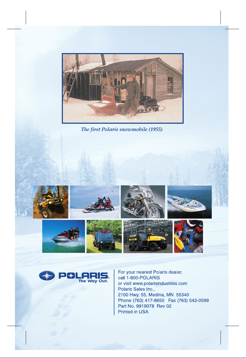
Stay Away From Moving Parts
WARNING
Never hold the snowmobile up or stand
behind it while warming up the track. A
loose track or flying debris could cause
serious personal injury or death.
We recommend having your dealer
perform track service and alignment
procedures.
Be alert when riding, and remain properly seated to stay clear of the
track. Your snowmobile is propelled by a revolving track that must be
partially exposed for proper operation. Serious injuries may result if
hands, feet, or clothing become entangled in the track.
WARNING
If fingers or clothing contact the moving parts of an engine,
serious injury can result. Always stop the engine before
attempting adjustments.
Never attempt adjustments with the engine running. Turn off the
ignition, raise the hood, make the adjustment, secure shields and
guards, secure the hood, and then restart the engine to check its
operation.
Riding Position
WARNING
Improper riding position may seriously reduce your ability to
control the machine and may result in serious injury or death.
Always be properly seated and in position to control your vehicle.
Operating a snowmobile requires skill and balance for proper control.
Rider positions may vary from person to person as each becomes more
skilled; but under most conditions, the proper position is to be seated
with feet on the running boards, and comfortably positioned for proper
throttle, brake, and steering control.
WARNING
Use of a backrest may hinder your weight shifting ability. This
could affect your ability to control this rider-active vehicle in
certain extreme driving situations.
10
Page 14
SAFETY
Operator Safety
Survival Preparation
For your safety, always ride in a group of other snowmobilers. Always
tell someone where you’re going and how long you expect to be gone.
If it isn’t possible to ride with others, and you must travel into remote
areas, always carry survival equipment that’s appropriate to the
conditions you may encounter. S uch equipment may include, but is
not limited to: extra clothing, a sleeping bag, a flashlight, food and
water, a signaling mirror, a means of building a fire, and a two-way
radio or cellular telephone.
For added protection, carry the following items on your snowmobile at
all times:
SSpare Drive Belt SExtra Set of Spark Plugs
STow Rope SExtra Oil
SFuel Deicer SWinter Survival Kit
STrail Map SOwner’s Manual
SFirst Aid Kit
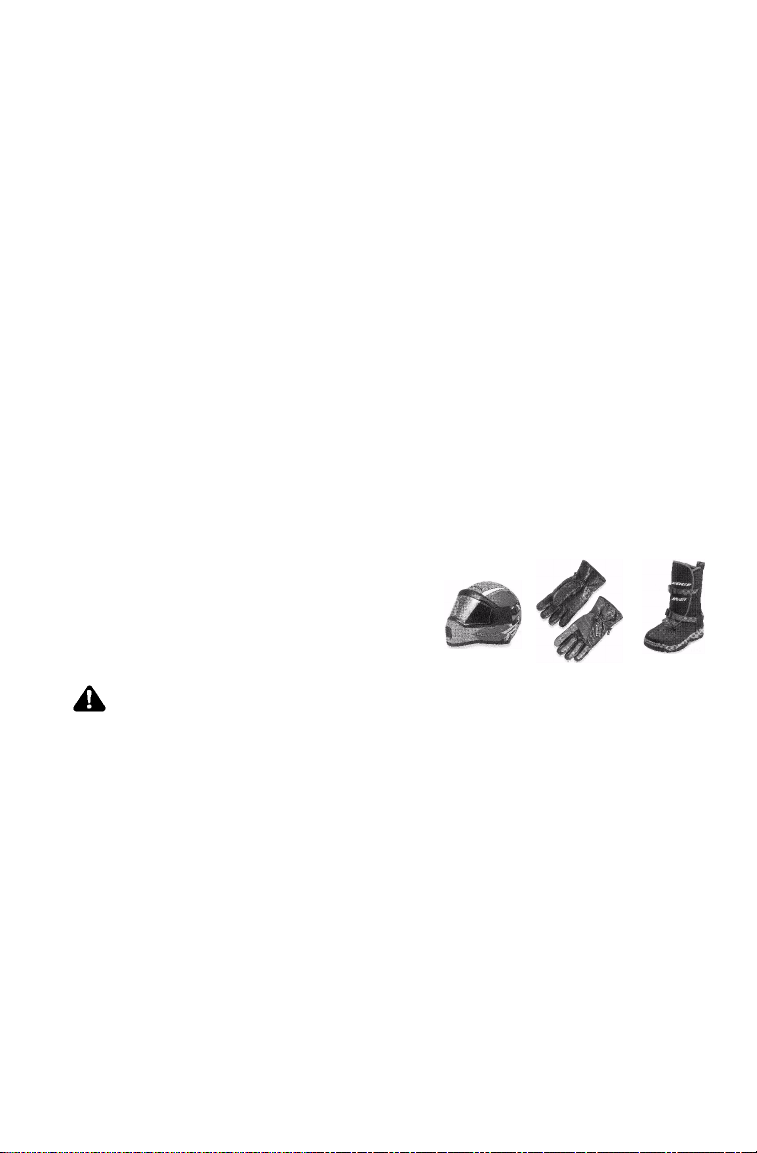
Riding Apparel
Be aware of the weather forecast and
especially the wind chill. A wind chill
table is provided on page 22 for your
reference. To better enjoy your ride, be
prepared, be warm and be comfortable.
WARNING
Loose clothing or long scarves may easily become entangled in
moving parts and cause serious personal injury.
Always wear an approved helmet and eye protection.
11
Page 15

SAFETY
Operator Safety
Disabled Operators
Safe operation of this rider-active vehicle requires good judgement and
physical skills. Operators with cognitive or physical disabilities have
an increased risk of loss of control, which could result in serious injury
or death.
Cargo Overload
Too much weight on the rear of the machine may reduce your ability to
steer. Do not exceed carrier and rack weight limits, and do not allow a
passenger to sit on the seat back or the cargo carrier.
WARNING
Control becomes more difficult with two people on board. More
space is required to make turns, and longer distances are needed
for stopping. Make sure the passenger remains seated behind
the driver, facing forward, with both feet placed firmly on the
running boards. Slow down and avoid “jumping” your
snowmobile.
Rider Capacities
Driving 1-Up - Some Polaris snowmobiles are designed for a single
rider only. A decal on the console of these models indicates single
rider operation.
Driving 2-Up - Some Polaris snowmobiles are designed for up to two
riders. A decal on the hood of these models indicates that the vehicle
is designed for one operator and one passenger only. See page 24 for
decal location.
Machines designed for two riders should never be operated with more
than two people on board. When traveling with a passenger, it’s the
driver’s responsibility to operate the machine safely.
Slow down! Control becomes more difficult with two people on board.
More space is required to make turns, and longer distances are
necessary for stopping.
12
Page 16

SAFETY
Operator Safety
Excessive Speed
WARNING
High speed driving, especially at night, could result in serious
personal injury or death. Always reduce speed when driving at
night or in inclement weather.
Observe all state and local laws governing s nowmobile operation.
They’ve been established for your protection.
Always be alert and pay attention to the trail ahead. Multiplying speed
(MPH) by 1.5 will equal the approximate number of feet per second
your machine travels. If your speed is 40 MPH, your machine is
traveling about 60 feet per second. If you look back for only two
seconds, your machine will travel about 120 feet. If your speed is 60
MPH, your machine will travel about 180 feet in two seconds.
Traveling at night requires extra caution. Check headlight and taillight
to ensure proper operation, and don’t over-drive your headlight beam.
Always be able to bring your machine to a stop in the distance
illuminated by the headlight.
13
Page 17

SAFETY
Operator Safety
Driver Awareness
Slow down when traveling near poles,
posts, or other obstacles. Be especially
alert if you’re snowmobiling after dark.
Always be on the alert for wire fences.
Single strands are especially dangerous,
since there may be a great distance
between posts. Guy wires on utility poles
are also difficult to distinguish.
Make sure the way is clear before crossing
railroads and other roads and highways.
The noise of your machine will drown out
the sound of approaching vehicles. Look
ahead, behind, and to both sides before
turning or crossing railroad tracks or
highways. Steep embankments may also
hide your view. Always leave yourself a
way out.
Variances in snow depth and/or water
currents may result in uneven ice
thickness. Always check with local
residents or authorities for general information on conditions when
traveling on lakes and streams that are strange to you. Before riding
your machine on a frozen body of water, be sure the ice is thick enough
to support the machine and its operator, as well as the force created by
a moving vehicle. You may drown if you and the snowmobile break
through the ice.
When teaching inexperienced operators to ride, set up a predetermined
course for practice. Make sure they know how to drive and control the
snowmobile before allowing them to make longer trips. Teach them
proper snowmobile courtesy, and enroll them in driver’s training and
safety courses sponsored by local or state organizations.
14
Page 18

SAFETY
Operator Safety
Avalanches
Snowmobilers should always be properly
trained and equipped before traveling in
mountainous terrain:
S Take an avalanche class
S Travel with experienced people
S Travel on designated trails
S Make sure each person is equipped with
a shovel, probe and avalanche beacon.
You don’t have to be snowmobiling on a slope for an avalance to occur.
Be aware that all of the snow is connected. You may be riding on a flat
slope or snow covered road, but if the snowpack above is unstable
enough you can trigger an avalanche on a steeper slope above you.
Always be aware of snow conditions above you as you travel in
mountainous terrain.
Before riding in mountainous terrain, call or log on to your local
avalanche advisory to get current weather and snow stability
information.
For more information about avalanche training and avalanche
conditions, contact local law enforcement in your area, or visit either
the American Avalanche Association online at
www .americanavalanceassociation.org or the U.S. Forest Service
National Avalanche Center at www.avalanche.org.
15
Page 19

SAFETY
Operator Safety
Ice and Snow Build-up
WARNING
Ice and snow build-up may interfere with the steering of your
machine, resulting in serious injury or death. Keep the
underhood area free of snow and ice.
Before driving, manually turn the skis to the left and right to be sure
ice and snow are not interfering with full left and right steering. If
difficulty is encountered, check for ice and snow build-up that may be
obstructing the steering linkage. Snow screens and bib kits are
available through your dealer to help reduce snow and ice build-up.
Driving on Slippery Surfaces
WARNING
Driving on ice or hard-packed snow reduces steering and braking
control, which may result in serious injury or death. Slow down
and use caution.
Excessive shifting of operator body weight when turning on
hard-packed snow or ice may lead to loss of vehicle control and result
in serious injury or death. Slow down to maintain control under these
conditions.
It’s dangerous to drive on ice or other slippery surfaces. If it’s
unavoidable, use extreme caution and operate at speeds no faster than a
walk. Never attempt an abrupt change of direction. The chance of
“spin-out” increases under these conditions.
16
Page 20

SAFETY
Operator Safety
Driving in Hilly Terrain
WARNING
Climbing a hill or crossing the face of a slope may result in loss of
balance and machine roll-over, causing serious injury or death.
Use caution and good judgement when driving in hilly terrain.
Operating in hilly terrain requires extreme caution to maintain balance
and avoid roll-over. If climbing a hill is unavoidable, keep all your
weight low and forward.
If you must cross the face of a slope, keep your weight on the uphill
side of the machine to maintain proper balance and avoid possible
roll-over.
Slow down when reaching the crest of a hill. Be prepared to react to
obstacles, sharp drops, or other people or vehicles that may be on the
other side of the hill.
If you’re unable to continue up a hill, turn the machine downhill before
it loses momentum. If this isn’t possible, spin the track just enough to
dig in to prevent it from rolling back down the hill. Stop the engine
and set the parking brake (if equipped). Keeping away from the
downhill side of the machine, pull the rear of the snowmobile around
and point the front end and skis downhill. Remount the machine,
restart the engine, release the parking brake, and descend the hill
carefully.
17
Page 21

SAFETY
Operator Safety
Driving Downhill
When riding downhill, shift your weight to the rear of the machine and
reduce your speed to a minimum. Apply just enough throttle to keep
the clutch engaged, allowing the engine’s compression to help slow the
machine and keep it from rolling freely downhill.
WARNING
When driving on long downhill stretches, pump the brakes.
Riding the brakes may cause the brake system to overheat,
which may result in brake failure.
Excessive or repetitive use of the brakes for high speed stops will
also cause an overheated brake system. This condition may lead
to a sudden loss of brakes and/or fire and may result in serious
injury or death.
Clutch Guard
Do not operate the engine with the clutch guard removed.
The clutch guard is designed to protect the operator from metal parts if
the clutch should fail. Although the chance of failure is extremely
remote, don’t defeat the purpose of the guard by removing it. It’s
provided for your safety.
Drive Belt
Do not operate the engine with the drive belt removed.
Any servicing that requires operation without a belt must be performed
by your dealer. Operation of the engine with the belt removed may
result in personal injury or damage to the engine.
18
Page 22

SAFETY
Operator Safety
Intake Silencer
Do not operate the engine with the intake silencer or filter removed.
Damage to the engine may occur if the intake silencer or filter are
removed.
Clutches
Do not attempt to service the clutches.
All clutch service must be performed by your dealer. The clutch is a
complex mechanism that rotates at high speeds. Each clutch is
dynamically balanced before installation. Any tampering may disrupt
this precision balancing and create an unstable condition.
Cold Weather Drive-Away
Whenever your snowmobile has been parked for a length of time,
especially overnight, always make sure the skis and track are loosened
from ice and snow before attempting to drive. Apply the throttle with
enough authority to put the machine into motion, but always operate
within safety limits and, on 2-Up machines, with respect for a
passenger. See Starting a Cold Engine on page 58.
Maneuverability
Control and maneuverability comes not only through the steering and
skis, maximum control is achieved by shifting of body weight.
Maneuverability will change for lighter operators or machines designed
to carry a load or a passenger.
Maintenance
Your Polaris snowmobile is a well-engineered and well-constructed
recreational vehicle. Follow the recommended maintenance program
outlined beginning on page 76 of this manual to ensure that all critical
components on the snowmobile are thoroughly inspected by your
dealer at specific mileage intervals.
19
Page 23

SAFETY
Operator Safety
Powder Snow Operation
Moveable hood closures are included on some Polaris snowmobiles.
They are normally left open and are located on the front upper and
lower hood openings. If operating in deep snow or in extreme cold
conditions (below -20_F), Polaris recommends closing the upper hood
closure.
WARNING
Do not drive for prolonged periods on blacktop, gravel, or ice.
Doing so could cause irreversible track damage and lead to
serious personal injury.
Since snow provides the only lubrication for the power slide
suspension and, on liquid cooled models, cooling for the engine,
adequate snow cover is a requirement for operation of your machine.
Driving in too little snow will result in excessive wear and damage to
the slide rail, track and/or engine.
If the machine becomes stuck in snow, clear the running board area of
snow, then step down the snow in front of the machine so that when
the throttle is opened, the snowmobile will be able to climb up and
over. You m ay then mount the machine and continue riding.
CAUTION
When operating on icy surfaces or hard-packed snow, avoid
overheating the slide rail and track. Lack of lubrication and
cooling will cause overheating of the slide rail and track, resulting
in premature wear and failure. If frequently operating in low
cooling conditions, see your dealer for an optional wheel kit that
will reduce the wear from overheating.
20
Page 24

SAFETY
Operator Safety
Driving Responsibly
Every snowmobile handles differently, and even the most docile
conditions may become dangerous if operators drive improperly. If
you’re new to snowmobiling, acquaint yourself with the machine and
with what it will and won’t do under various conditions. Even
seasoned drivers should spend some time getting the feel for a machine
before attempting ambitious maneuvers.
S A snowmobile depends on the rider’s body position for proper bal-
ance in executing turns, traversing hills, etc. Always start on a
smooth, level area to begin building your operating experience.
S Before allowing someone else use your snowmobile, know the ex-
tent of their operating skills. Check to see if they’ve taken a snowmobile safety course and have an operator’s certificate. For their
protection, as well as yours, make sure they take a snowmobile safety course. Everyone can benefit from the course.
S Don’t “jump” your snowmobile. Jumping may injure your back be-
cause of spinal compression. The seat and suspension of your snowmobile have been designed to provide protection under normal
riding conditions. Your snowmobile is not intended for this kind of
use.
S Be courteous to oncoming traffic by dimming your headlights and
reducing your speed. Your snowmobile is equipped with a high output headlamp system that may cause discomfort to operators of oncoming vehicles when on high beam.
S When traveling in a group of snowmobiles, don’t tailgate (follow too
closely). Allow ample stopping distances, and keep track of those
following you. Drive defensively to avoid accidents.
S Remove the key from the ignition.
21
Page 25

SAFETY
aveLit
tleAdde
d
Clo
the
dPers
on)
HaveLittleAdded
ClothedPerson
)
A
f
f
C
)
Operator Safety
Windchill/Temperature Charts
The following information is provided to help you determine when
temperatures become dangerous for riding.
WIND CHILL CHART (°F)
Estimated Wind
Speed in MPH
Calm 50 40 30 20 10 0 -10 -20 -30 -40 -50 -60
5 48 37 27 16 6 -5 -15 -26 -36 -47 -57 -68
10 40 28 16 4 -9 -21 -33 -46 -58 -70 -83 -95
15 36 22 9 -5 -18 -36 -45 -58 -72 -85 -99 -112
20 32 18 4 -10 -25 -39 -53 -67 -82 -96 -110 -124
25 30 16 0 -15 -29 -44 -59 -74 -88 -104 -118 -133
30 28 13 -2 -18 -33 -48 -63 -79 -94 -109 -125 -140
35 27 11 -4 -20 -35 -49 -67 -82 -98 -113 -129 -145
40 26 10 -6 -21 -37 -53 -69 -85 -100 -116 -132 -148
Wind Speeds Great-
er Than 40 MPH
H
Effect
50 40 30 20 10 0 -10 -20 -30 -40 -50 -60
Little Danger
(For Properly
Actual Thermometer Reading (°F)
Equivalent Temperature (°F)
Increasing
Danger
Danger From Freezing of Exposed Flesh
Great
Danger
WIND CHILL CHART (°C)
Estimated Wind Speed
inKPH
0 5 0 -5 -10 -15 -20 -25 -30 -35 -40
10 1 -4 -11 -16 -22 -27 -33 -38 -45 -50
20 -4 -9 -17 -23 -29 -36 -42 -48 -54 -61
30 -7 -13 -21 -28 -35 -42 -48 -55 -63 -69
40 -9 -16 -24 -32 -39 -47 -53 -61 -69 -76
50 -11 -18 -26 -34 -41 -49 -57 -64 -73 -80
60 -12 -19 -27 -35 -43 -51 -59 -66 -75 -82
70 -13 -20 -28 -36 -44 -52 -60 -68 -76 -84
Wind Speeds Greater
Than 70 KPH Have Little
dded E
ect
22
Actual Thermometer Reading (°C)
5 0 -5 -10 -15 -20 -25 -30 -35 -40
Equivalent Temperature (°C)
Little Danger
(For Properly
lothed Person
Increasing
Danger
Danger From Freezing of Exposed Flesh
Great
Danger
Page 26

SAFETY
Safety Decals and Locations
Warning decals have been placed on the snowmobile for your
protection. Read and follow the instructions of the decals and other
warnings on the snowmobile carefully. If any of the decals depicted in
this manual differ from the decals on your snowmobile, always read
and follow the instructions of the decals on the snowmobile.
If any decal becomes illegible or comes off, contact your Polaris dealer
to purchase a replacement. Replacement safety decals are provided by
Polaris at no charge. The part number is printed on the decal.
Clutch Cover Warning
This warning decal is found under the hood on the clutch cover:
Do not operate engine with hood open.
Do not attempt adjustment with engine running.
Do not operate engine with this guard open.
Never run engine with drive belt removed.
Never service clutches yourself - see your dealer.
Air Bo x Warning
This warning decal is found under the hood on applicable models:
CAUTION
Do not operate above 40 mph with hood-to-airbox
foam removed or engine failure will result.
Pressure Cap Warning
This warning decal is found on the coolant bottle cover of liquid
cooled models:
WARNING
Do not open hot.
Test or replace when changing coolant.
Press down and turn to release cap.
13 PSI
23
Page 27
SAFETY
Safety Decals and Locations
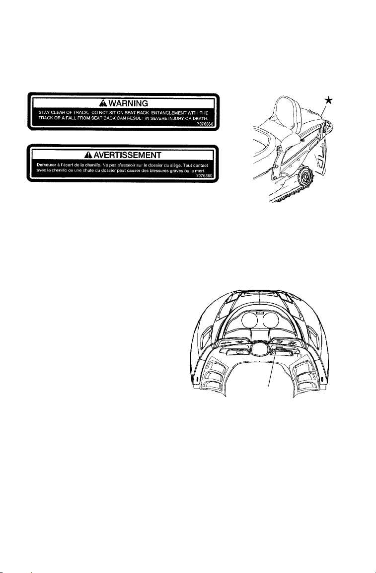
Track Warning
The track warning decal is located on the rear of the tunnel:
Cargo Carrier Warnings
Machines with a cargo carrier have a cargo weight decal at the rear of
the snowmobile. The decal specifies the maximum recommended
weight capacity for the carrier. Never exceed the maximum
recommended weight capacity for your machine.
Passenger Warning
Polaris touring models and the
WideTrak are designed for the
operator and one passenger. For
more information on operating
with a passenger, see page 12.
The passenger warning decal is
located at the right side of the
steering post:
+
This vehicle is designed for
operator and “ONE” passenger
only.
24
Page 28
Safety Decals and Locations
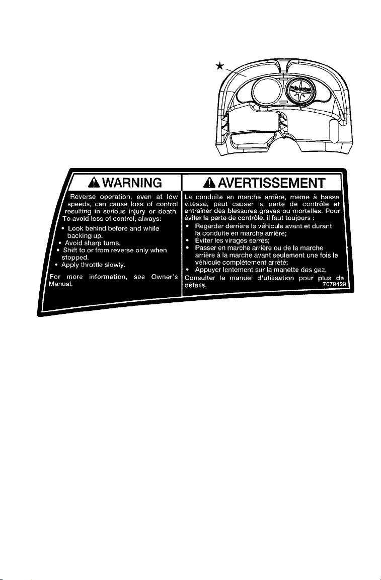
Standard Reverse Warning
The Polaris WideTrak snowmobile
is equipped with standard reverse.
The reverse warning decal is
located above the instrument
housing.
SAFETY
25
Page 29
SAFETY
Safety Decals and Locations
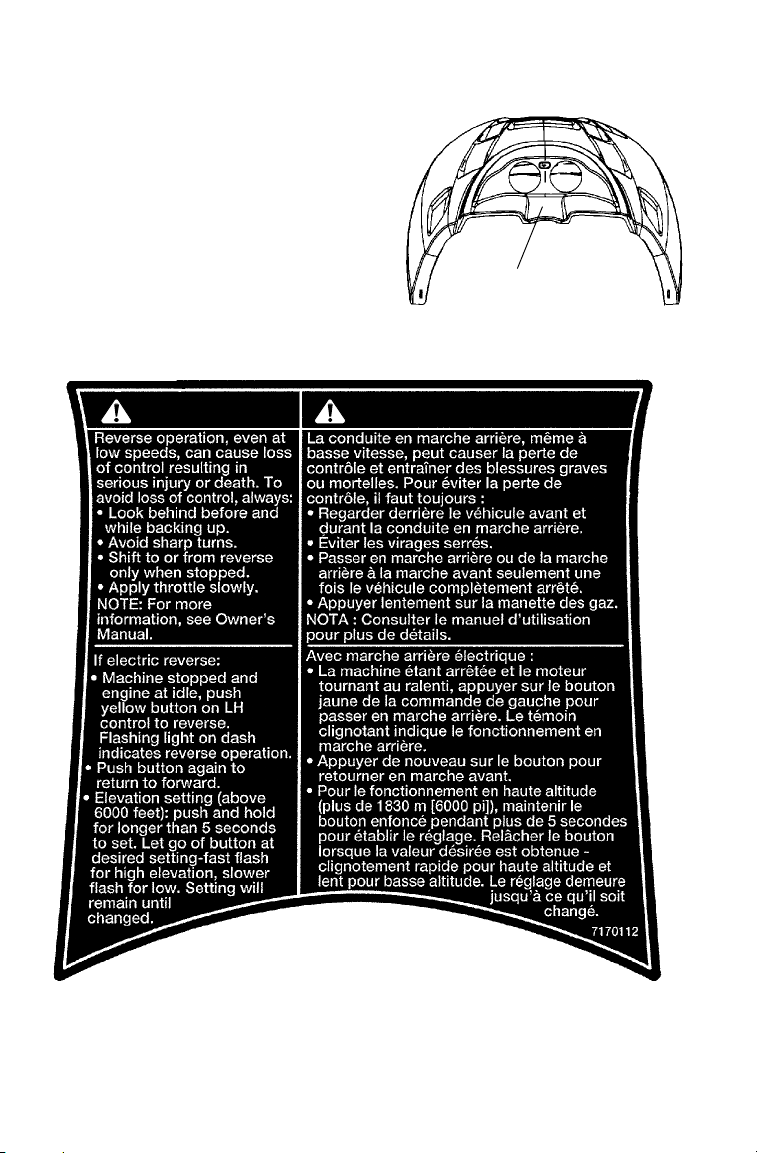
Electronic Reverse Warning
Polaris snowmobiles
equipped with electronic
reverse will have the
electronic reverse warning
decal.
WARNING AVERTISSEMENT
+
26
Page 30
Safety Decals and Locations
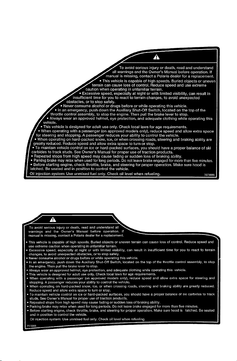
Operation Warning
Operation warning
decals are present on
the console of all
Polaris snowmobiles, in
both French and
English.
Touring Models
SAFETY
WARNING
WideTrak
WARNING
27
Page 31

SAFETY
Safety Decals and Locations
Operation Warning
AVERTISSEMENT
Touring Models
WideTrak
28
AVERTISSEMENT
Page 32

FEATURES
Some Polaris snowmobiles are equipped with special features.
Operating controls and special feature controls are illustrated on this
page. Not all models come with all special features. Refer to your
Owner’s Manual Supplement for the features on your machine.
6
5
4
3
2
1
1. Fuel Filler Cap
2. Ignition Switch
3. Accessory Plug
4. Brake Lever
5. Electronic Fuel Gauge
6. Speedometer
7. Tachometer
8. Electric Shock Control
Gauge
9. Engine Stop Switch
10. Throttle Control
11. Hood Hold Down Straps
12. Recoil Starter Handle
13. Choke
14. Headlight Dimmer Switch
15. Park Brake Lock
16. Handlebar Grip Warmer
Switch
17. Thumbwarmer Switch
18. Electronic Reverse Button
19. Electronic Shock Control
Button
14
7
8
9
10
11
12
13
15
16
14
16
17
18
19
29
Page 33

FEATURES
8
3
4
5
7
6
9
10
2
1
18
19
1. Hood
2. Headlight
3. Passenger Lumbar Adjuster
(Touring models)
4. Windshield
5. Handlebar
6. Operator Seat
7. Passenger Seat
8. Trunk Cover
9. Taillights
10. Rear Bumper
17
11
12
13
14
15
20
16
1 1. Snow Flap
12. Passenger Grab Handle
13. Track
14. Suspension
15. Trailing Arm
16. Nosepan
17. Front Bumper
18. Skis
19. Grab Handle Heater Switch
20. Passenger Hand Hold Strap
(WideTrak)
30
Page 34

THE PERFECT FIT
Front Suspension Adjustments
Break in the suspension for approximately 150 miles (240 km) and
re-grease all suspension parts before making any fine-tuning
adjustments.
Settings will vary from rider to rider, depending on rider weight,
vehicle speed, riding style, and trail conditions. We recommend
starting with factory settings and then customizing each adjustment
individually to suit rider preference. The machine should be
methodically tested, one change at a time, under the same conditions
(trail and snow conditions, vehicle speed, riding position, etc.) after
each adjustment until the best ride is achieved.
Independent Front Suspension (IFS)
The IFS is made up of the skis (1),
front shocks and springs (2), and the
components that connect these parts
to both the steering, such as the tie
rods (3), and to the machine itself,
such as the trailing arms (4).
Front suspension adjustments
include shocks, springs, toe,
and camber .
NOTE: Although the front
suspension on your
machine may not
look exactly like the
illustration, it will have
the same parts and
functions as those illustrated.
1
2
3
4
IFS Adjustment Options
S Shock damping (if equipped with Indy Select or RydeFX SOLO
shocks)
S Front shock spring preload
S Optional springs
S Optional shock valving (if equipped with RydeFX shocks)
S Toe (ski alignment) (see page 120)
S Camber (see your dealer)
31
Page 35

THE PERFECT FIT
Front Suspension Adjustments
WARNING
Always verify ski alignment before making adjustments to the
IFS. See page 120 to check alignment. If the skis are misaligned,
see your dealer, as the camber adjustment may also be affected.
For the best ride, the suspension should be adjusted to use the full
travel of the shocks with occasional light bottoming. To determine if
your machine is using full travel, push the jounce bumper down on the
shock rod until it contacts the body and test ride the machine. The
bumper will move up on the rod in relation to the amount of travel that
was used during the ride. If the travel is full, the bumper will be seated
at the top of the rod.
Shock Absorber Components
1. Retainer
2. Shock Rod
3. Jounce Bumper
4. Body
5. Threaded Spring Preload Adjuster Nut
1
2
3
4
5
32
Page 36

THE PERFECT FIT
Front Suspension Adjustments
Shock Damping
Adjustments to the compression
stiffness of Indy Select or
RydeFX SOLO shocks can be
made by turning the adjustment
screw (Select) or actuator
(SOLO), located near the base of
the shock (A). This adjustment is
the easiest to perform and it
should be considered first. A
clockwise adjustment will
increase stiffness in both styles of
shock, but there are some
differences.
Indy Select Shock
The factory setting for this shock is the softest position, with the
adjusting screw all the way out (counterclockwise). If bottoming
occurs, the Indy Select feature should be used to achieve the desired
ride. The shocks have a wide range of adjustment capability. By
turning the screw clockwise, the compression of the shock increases,
stiffening the ride. When adjusting these shocks, we recommend that
you turn the screw only 1/4 turn at a time, then test ride. Always
adjust both shocks equally.
A
RydeFX SOLO Shock
The factory setting for this shock is at
medium stiffness, with the clicker
knob (B) set at position 4. The
clicker can be actuated with the
thumb and forefinger. If bottoming
occurs, rotate the clicker clockwise to
the next higher number. If full shock
travel isn’t being used, rotate the
clicker counterclockwise to the next
lower number. When adjusting these
shocks, we recommend that you turn
the clicker only one click at a time,
then test ride. Always adjust both
shocks equally.
B
33
Page 37

THE PERFECT FIT
Front Suspension Adjustments
Adjusting Front Shock Spring Preload
Increasing spring preload will increase
ski-to-ground pressure. Decreasing spring
preload will decrease ski-to-ground
pressure. When adjusting, be sure the
springs on both the left and right sides of
the machine are at the same adjustment.
To increase front shock spring preload,
grasp the spring and turn it to the right.
Turn it to the left to decrease preload.
Illustration B indicates high preload and
illustration C indicates low preload.
Increasing the spring preload too much may adversely affect the
handling of the snowmobile and the performance of the suspension.
Never exceed one inch of preload beyond the factory settings, and
ensure that both sides are adjusted the same. When decreasing preload,
make sure at least two turns of preload are holding the spring between
the retainer on top of the shock and the threaded spring preload
adjuster nut on the shock body.
CB
NOTE: Not all models have shocks with thread adjustable spring
preload. See your dealer for more information.
CAUTION
Always leave one thread showing above the adjuster nut. On
models equipped with a plastic adjuster nut, if the nut is
unscrewed from the threaded body, the nut will break.
34
Page 38

THE PERFECT FIT
Front Suspension Adjustments
Shock Valving
RydeFX or RydeFX SOLO shocks can be revalved if spring preload
alone isn’t sufficient and further adjustment is desired to control
suspension stiffness.
WARNING
Changing shock valving on RydeFX and RydeFX SOLO shocks
requires special tools and a sound knowledge of mechanical
theory, tool use, and shop procedures to perform the work safely
and correctly. Shocks contain high-pressure nitrogen gas. Use
extreme caution when handling high-pressure service equipment.
We recommend that this work be performed by a Polaris dealer.
Front Springs
For models without externally adjustable or revalvable shocks, the
front springs can be changed if spring preload alone isn’t sufficient and
further adjustment is desired to control suspension stiffness. See your
Polaris dealer for more information.
35
Page 39

THE PERFECT FIT
Rear Suspension Adjustments
Rider weight, riding style, trail conditions, and vehicle speed all affect
suspension action.
Each rear suspension can be adjusted to suit rider preference and
deliver excellent performance for a given set of conditions. However,
all suspension designs and adjustments involve a compromise, or
trade-off. For example, a suspension set up for snow-cross racing
would provide a very stiff ride on the trail. A suspension set up for
trail riding would bottom out harshly on a snow-cross course.
A decal outlining rear suspension set-up options is located either under
the hood or on the clutch cover. It provides a guideline for initial
suspension set-up. Additional adjustments can be made from this
point. Make adjustments to one area at a time so you can evaluate the
change. For further assistance, see your dealer.
Suspension Performance Tips
S Rider weight usually determines the position at which the spring pre-
load should be set. However, this may vary with riding style. With
a little experimentation, each rider can find a preferred set-up. These
adjustments are easy to make, involve very little time or effort, and
greatly affect the ride.
S In deep snow, a new Hi-fax will offer improved performance over
worn Hi-fax. It can also improve top speed.
S When riding on ice or hard-packed snow, adding a set of bogie
wheels to the rail may enhance the machine’ s performance. Bogie
wheel kits are available from your dealer.
S Polaris offers track kits for improved flotation in deep snow. See
your dealer for assistance.
NOTE: Keep the suspension pivot points lubricated. This will reduce
36
moisture and rust build-up and ensure proper function of the
suspension components. Grease rear suspension pivots
before adjusting the rear suspension. Refer to Suspension
Maintenance beginning on page 124.
Page 40

THE PERFECT FIT
Edge 136 Rear Suspension Adjustments
(Indy 340 Touring)
Initial Spring Preload Setting (Sag Method)
To set up t he EDGE rear suspension
torsion spring preload, measure the
distance between the ground and rear
bumper. This is measurement X.
Take the first measurement with no
rider and with the rear suspension at
full extension.
X
NOTE: The rear bumper may need
Next, have the rider drop down hard
on the seat and bounce up and down
several times, collapsing the rear
suspension. With the rider seated,
measure the distance between the
ground and the rear bumper at the
exact location used for measurement
X. This is measurement Y.
To determine sag, commonly referred to as ride-in, subtract
measurement Y from X (Sag=X-Y). Adjust sag by rotating the torsion
spring preload cams located on the rear torque arm. Use the illustration
or the decal found under the hood for reference. The ideal amount of
Sag for the EDGE rear suspension is four inches (X-Y=4).
If the rear suspension rides in less than three inches or more than five
inches with the torsion spring preload cams at their maximum range of
adjustment, optional torsion springs (softer or stiffer, respectively) may
be required. This is only an initial set-up, and final spring preload may
vary based on rider preference and riding conditions.
to be lifted upward slightly
to fully extend the rear
suspension.
Y
37
Page 41

THE PERFECT FIT
Edge 136 Rear Suspension Adjustments
(Indy 340 Touring)
Rear Spring Tension
To adjust rear torsion spring tension, rotate the three-position cam
using the engine spark plug tool.
Different rate torsion springs are available if a firmer ride is desired.
Contact your dealer for more information.
The following information is provided only as a guideline to be used
for initial suspension set-up. Your set-up may vary based on your
desired riding style.
A-Lowtension
B - Medium tension
C - High tension
Indy Select Rear Shock
The Indy Select rear shock allows for adjustments to the compression
valving. Locate the adjustment screw (A) near the base of the shock.
In half-turn increments, turn the screw clockwise to increase
compression valving and stiffen the ride, or counterclockwise to reduce
compression and soften the ride. There are approximately three full
turns of adjustment available.
If bottoming continues
after the screw has been
turned fully clockwise,
the torsion spring should
be adjusted (see page 38).
Return the screw to its
original starting position
after the torsion spring
has been tightened.
AB
A
C
38
Page 42

THE PERFECT FIT
Edge 136 Rear Suspension Adjustments
(Indy 340 Touring)
Optional Coil Springs
Different rate coil springs are available for some shocks if a firmer ride
is desired. Contact your dealer for more information.
Suspension Coupling
On all Polaris snowmobile rear suspensions, there are two torque arms
that control the movement of the rail beam. Prior to the advent of
suspension coupling, these torque arms could move independently of
each other. Rear suspension coupling links the movement of the front
and rear torque arms to each other. There are two types of rear
suspension coupling.
Front To Rear Coupling and the Front Rear Scissor
Stop (FRSS)
The front rear scissor stop (FRSS) couples the movement of the front
torque arm with the rear torque arm and limits the amount of
independence between the movement of the front torque arm and the
rear torque arm.
When hitting a bump, the front torque arm starts to compress. The
FRSS links that movement to the rear torque arm, causing it to
compress and raise the rear suspension up as one, allowing the
suspension to hit the bump only once and eliminating kickback. Your
FRSS is preset at the factory.
39
Page 43

THE PERFECT FIT
Edge 136 Rear Suspension Adjustments
(Indy 340 Touring)
Rear To Front Cou p lin g and the Rear Rear Scissor
Stop (RRSS)
The rear rear scissor stop couples the movement of the rear torque arm
with the front torque arm and limits the amount of independent
movement between the rear torque and the front torque arm.
Adjusting the RRSS either allows more weight to transfer to the rear
for more traction, or allows less weight to transfer to the rear, resulting
in improved cornering performance. An adjustment dot is located on
the RRSS. This dot is on the longest end of the scissor stop.
RRSS Attributes
Moving the RRSS to a higher position, or forward hole, will have the
following effects on the suspension:
S Reduced weight transfer
S Improved chatter bump ride
S Improved cornering performance
40
Page 44

THE PERFECT FIT
Edge 136 Rear Suspension Adjustments
(Indy 340 Touring)
Weight Transfer During Acceleration
Rear Rear Scissor Stop (RRSS)
The preferred m ethod for controlling weight
transfer during acceleration of the EDGE rear
suspension is by adjusting the RRSS. The
RRSS is located in the best overall trail riding
position when delivered from the factory.
T o decrease weight transfer under acceleration (for
improved cornering), rotate the RRSS to a higher
position with the scissor stop tool (1) located in your tool kit.
To increase weight transfer or ski lift during acceleration, move the
RRSS to the rearward hole on high position. The RRSS may also be
rotated to a lower position for even more weight transfer if desired.
A - Stock Position - This setting is
most desirable for trail riding.
B - Medium or High Position (standard
hole location) - This setting will
decrease weight transfer.
C - Rearward Upper Position (optional
hole location) - This setting will
increase weight transfer.
1
A
B
NOTE: Your dealer can help you with
initial set-up and additional
set-up instructions to help
you achieve your optimum
ride.
C
41
Page 45

THE PERFECT FIT
Edge Touring Suspension (ETS) Adjustments
Torsion Springs
Two torsion springs are used on the rear arm of
the ETS. Preload adjustments can be made by
turning the rectangular adjusters with a spark
plug wrench.
The firm torsion spring should be used if
frequent bottoming is encountered during two
up riding on rough trails.
The soft torsion spring should be used for
frequent one up riding on smooth trails.
For soft tension, position the long end of the
cam to the front (A). For firm tension, position
the long end of the cam up (B).
D
Front Track Spring and Preload
Front track spring and preload can also be
adjusted. Turn the screw (C) clockwise to
tighten compression (stiffen). Turn t he
C
spring (D) clockwise to tighten preload.
Initial Setup Reference Chart
This chart is only a guideline for initial suspension setup. Your setup
may vary based on your desired riding style.
A
B
1 Rider Soft
Firm
2 Riders Soft
Firm
Soft
Firm
42
Tors i on
Spring & Block
Setting
Low
Med
Med
High
Optional Torsion Spring Optional Front Track
Left Hand Right Hand
7042139-067
7042282-067
RCA
Position
1-2
2-3
3-4
4-5
7042140-067
7042283-067
Front Track
Spring Preload
(Inches)
0.25
0.50
0.75
1.00 max
7041351-067
Indy Select -
Spring
-------------
Front Track
Turns From
Full Open
0-1
1-2
1-3
2-3
Page 46

THE PERFECT FIT
Edge Touring Suspension (ETS) Adjustments
Initial Setup and Calibration
The following information has been compiled to assist you in tuning
your ETS to its maximum potential.
The Ride Control Adjuster (RCA)
1. Refer to the initial setup reference chart (located under t he hood of
your snowmobile and on page 42) to determine the desired RCA
position.
2. To adjust, loosen the hex bolts (A) attaching the rear lower shock
cross shaft to the rail beam.
3. Using a 9/16” wrench, loosen the jam nuts (B) on the preload
bolts.
4. Adjust the preload bolts (C) to the desired RCA position.
5. Tighten the jam nuts (B).
NOTE: Make sure the preload bolt contacts the slide block before
tightening the jam nut.
6. Tighten the hex bolts (A) and torque to 35 ft. lbs. (47 Nm).
NOTE: The RCA setting is the primary rear suspension adjustment.
Front Arm Mounting Holes
There are also
two front arm
mounting holes in
the slide rail that can
adjust ski pressure. The
lower hole (C) increases ski
pressure while the upper hole (D)
decreases ski pressure.
It will have the MOST effect on rear suspension performance.
A
B
C
D
C
43
Page 47

THE PERFECT FIT
ETS ACE Adjustments
The ETS ACE (Adjustable Control Electronics) is a new feature
available for some ETS rear suspensions. It enables a rider to easily
adjust the suspension for weight and riding style.
The ETS ACE is an electronically controlled module that replaces the
standard ETS RCA. The ACE changes the rear shock motion ratio by
moving the lower shock pivot point a total of 1 1/4 inches, the same
amount of adjustment as the standard RCA. A gauge on the console
displays the current position of t he shock, from soft to firm or
somewhere in between.
ETS ACE Settings
A switch labeled “ESC” on the left-hand control assembly is used to
adjust the position of the ACE module. The following instructions
describe all the features programmed into the ACE module.
1. By pressing the left hand control switch up (firm) or down (soft)
one time, the lower pivot moves .14 inch, giving the operator a
total of nine distinct positions. The console gauge will show the
current ACE position.
2. If the soft or firm switch is pressed more than one time in
succession, it will adjust as many increments as the switch is
pressed. The electronics will “do the math” for the user to
minimize travel time. For example, if the rider pushes “firm”
twice, and then “soft” three times, the unit will move to one
position softer than the current position.
3. If the soft or firm switch is held for five seconds or more, the ACE
will adjust to the far end of the travel, corresponding to which
button was pressed.
4. A fail-safe mode has been programmed into the controller to
protect the electronics and to notify the operator of a system
malfunction. If the module cannot adjust the suspension after one
of the switches has been pressed (most likely due to an obstruction
or heavy ice buildup), the controller will enter a failure mode,
which is indicated by the gauge needle moving rapidly between
soft and firm. This mode will continue indefinitely and is reset
when the engine is turned off and restarted. If this mode is
encountered, we recommend that the operator turn off the engine
and inspect the unit for any obstruction or ice buildup on the shock
or module.
44
Page 48

THE PERFECT FIT
ETS ACE Adjustments
ETS ACE Settings
IMPORTANT NOTES:
The time to move one position can take up to 12 seconds depending on
the rear shock loads.
Due to alternator limitations, the ACE module will operate only at
engine speeds above 3500 RPM.
Similar to the RCA on the standard ETS, the ACE module will have
the MOST effect on rear suspension performance.
45
Page 49

THE PERFECT FIT
WideTrak Rear Suspension Adjustments
Rear Spring Settings
Rear spring adjustment is primarily a control for riding comfort. To
check for the recommended settings:
1. Lift the rear of the m achine to relieve the rear springs.
2. Slowly lower the machine and measure the distance between the
ground and the running board.
3. Without letting the suspension settle, the rider should carefully
mount the snowmobile.
4. Measure the distance between the ground and the same spot on the
running board.
The difference between the two readings should be approximately 1
1/2″ (3.8 cm). If the difference is greater than 1 1/2″, the rear spring
should be adjusted equally on both sides until the desired 1 1/2″ drop is
obtained.
Compensating adjustments for heavy or light drivers or cargo loads can
be made by adjusting the rear spring eye bolt (A) length. Adjust spring
tension so there is equal tension on the long leg of each spring.
A
NOTE: Rear spring settings will affect ski-to-ground pressure. If ski
pressure is too light it may be desirable to tighten the rear
springs for an increase in ski-to-ground pressure.
46
Page 50

THE PERFECT FIT
Handlebar Adjustment
Follow these steps to adjust the handlebars for a personal fit.
1. Remove the handlebar cover to
expose the handlebar and the four
adjuster block bolts (A).
2. Using a 7/16″ (11 mm) wrench,
loosen the four nuts on the bottom
of the adjuster block (turn handlebar
to left or right for access to back
nuts).
NOTE: It may be necessary to pry the adjuster blocks apart with a
screwdriver.
3. Adjust the handlebar to the desired height. Be sure handlebars,
brake lever and throttle lever operate smoothly and do not hit the
gas tank, windshield or any other part of the machine when turned
fully to the left or right.
4. Torque the handlebar adjuster block bolts to 11-13 ft. lbs. (15-17.5
Nm).
5. Replace the handlebar cover.
Passenger Grab Handle Adjustment
On some Touring models the position of the
passenger grab handles can be adjusted for
rider preference. To make an adjustment:
1. Unscrew and remove the knob
assemblies (A) that secure the grab
handles.
2. Reposition the grab handles to one of the
three available positions on the grab
handle tube between the operator seat
and the passenger seat.
3. Reinstall the knob assemblies and
tighten securely.
A
A
47
Page 51

THE PERFECT FIT
Accessories
Polaris offers a wide range of accessories for your snowmobile. From
map light to electric start, Polaris has the accessories that will help
make each ride more enjoyable. See your dealer for a list of
accessories.
NOTE: The accessory tether switch is available for all models.
Use only Polaris parts and accessories on your Polaris snowmobile.
Use of unapproved parts and accessories may result in:
S Non-compliance with government/industry requirements
S Voiding of warranty
S Personal injury to self or others
This applies to, but is not limited to the following areas: brakes,
clutches, fuel systems, and exhaust systems.
NOTE: Exhaust systems are critical safety areas that must use
Order PN 2870668.
approved Polaris parts. Please see your Polaris dealer for
service.
48
Page 52

THE PERFECT FIT
Accessories
Traction Products
Another way to tailor your machine is to install traction products. See
your dealer about installing studs and/or carbides. Many tracks with
deep lug designs cannot be studded, but your dealer will be able to
offer advice and assistance.
NOTE: Polaris does not recommend the use of traction products on
NOTE: Before equipping your machine with traction products, be
Track studding will enhance braking control on hard-packed snow or
ice, but extreme caution is still required on such surfaces. Steering
ability may be reduced on hard-packed snow or ice.
A skag is a replaceable bar attached to the underside of the ski to assist
in turning the snowmobile and to prevent ski wear caused by contact
with roads and other bare terrain. The addition of carbide skags is
recommended with studded tracks to help maintain proper vehicle
steering and control. Similarly, if your machine is equipped with
carbide skags or you’re adding them, it may be necessary to add track
studs to maintain proper vehicle control. Proper balance must be
maintained between the number of studs and the length of carbide on
skags. The more studs used, the longer the carbide on the skags should
be. See your dealer’s track studding chart for recommended studding
and skags.
WideTrak snowmobiles.
aware of the laws in your area pertaining to the use of
traction products.
n Inspect skags and studs frequently. Worn studs or skags may
reduce steering and braking control on hard-packed snow and ice.
Replace worn studs and skags to maintain proper balance and vehicle
control.
When studded tracks are used, increased wear to the brake pads will
result from increased braking. Extended-wear brake pad kits are
available. See your dealer for more information.
49
Page 53

THE PERFECT FIT
Accessories
Use only Polaris traction products on your snowmobile. Track
warranties are void if track damage or failure results from improper or
excessive stud installation or the use of non-Polaris traction products.
CAUTION
Aggressive studding patterns may require grinding protruding
stud bolts flush to prevent idler wheel damage. Maintain track
tension on studded tracks on the tight side of the spec to prevent
heat exchanger damage. Center of stud must be at least 1 1/8″
(2.86 cm) from the outside edge of the track.
CAUTION
If traction products are added to the track, wear strips must be
installed in the tunnel to avoid excessive wear.
Never add shims to the wear strip. Track damage will result
because of lack of clearance between upper carrier wheels and
track.
Use of studs longer than the recommended length on machines
equipped with center coolers will result in center cooler damage
or damage to the tunnel.
WARNING
Loss of control can result in serious personal injury or death.
Proper balance of traction products on the skis and track must be
maintained to obtain proper vehicle control on hard-packed snow
or ice. See your dealer for assistance.
50
Page 54

THE PERFECT FIT
Accessories
Wear Strips
To avoid excessive tunnel wear, tunnel wear strips must be installed
whenever track studding is used. Several wear strips are available.
See your dealer for more information.
Some models are manufactured with tunnel wear strips or wear strip
coolers installed. Wear strips are designed for a specific stud length.
See your dealer’s studding chart for recommended traction accessories.
Components as viewed from the rear of the track:
1. Top of tunnel
2. Wear strip
3. Track
4. Wearstrip mounting holes
1
2
4
3
CAUTION
Whenever wear strips are relocated, be sure there’s adequate
stud clearance to the heat exchangers. Lack of clearance may
result in damage to heat exchangers.
51
Page 55

PRE-RIDE INSPECTIONS
SeeP
Pre-Ride Checklist
Inspect all items on the checklist for proper operation or condition
before each use of the snowmobile. Procedures are outlined on the
referenced pages. Look for a checkmark (n) on the referenced pages
to locate the pre-ride inspection items.
Item
Drive Belt Condition 111, 11 3
Recoil Rope 56
Coolant Level 98
Park Brake Lock/Brake Lever/Brake System 54, 55, 102
Auxiliary Shut-Off Switch (Engine Stop Switch) 57
Ignition Switch 57
Taillight/Brakelight/Headlight 57
Suspension Mounting Bolts 125
Skags (Wear Bars) 49, 123
Ski Saddle and Spindle Bolts 125
Steering System 56
Hood Straps/Latches 56
Seat Latches (if equipped) 56
Throttle Lever/Safety Switch 53, 68, 69
Rear Wheel Idler Bolts 118, 125
Tether Switch/Strap 57
Track Alignment/Condition 56, 119
Hi-Fax Condition 124
Chaincase/Gearcase Oil 88, 89
Injection Oil Level 66
age
52
Page 56

PRE-RIDE INSPECTIONS
Before Starting the Engine
WARNING
Worn, damaged, or malfunctioning components may cause
serious injury or death. Before starting the engine, check all
components to be sure of proper operation.
Read and Understand Your Owner’s Manual
Read the Owner’s Manual completely and refer to it often. We’ve
attempted to provide as much information as possible to alert you to
the safety requirements of snowmobiling.
n Check Throttle and Brake for Proper Operation
The throttle and brake are the primary controls of your snowmobile. If
either should malfunction, loss of control could result.
Make sure the throttle lever compresses evenly and smoothly. The
lever should immediately return to the idle position without binding or
hesitation. If the throttle does not function smoothly, or if you
discover excessive lever freeplay, DO NOT start the engine. Have the
throttle serviced immediately.
The need for a properly functioning brake is critical. Your snowmobile
is equipped with the highest quality brake system available. Check the
brakes for correct operation before starting the engine. See page 102.
n Throttle Safety Switch
Test the throttle safety switch system before the machine is operated.
See page 68 for procedure.
53
Page 57

PRE-RIDE INSPECTIONS
Before Starting the Engine
n
Hydraulic Brakes
Properly functioning brakes
are critical to your safety.
Always check the following
items to assure proper
operation before starting the
engine.
Brake Lever Travel
When the brake lever is
squeezed, it should move no
closer to the handgrip than
1/2″ (1.3 cm) (A). A
distance less than this indicates low brake fluid level or air in the
hydraulic system. Refer to the brake bleeding information on page 105.
Lever Feel
A hydraulic system multiplies the force of your hand squeezing the
brake lever. Proper operation depends on an adequate supply of air and
moisture-free hydraulic brake fluid in the system. If the brake lever
feels “spongy” when squeezed, check the level and condition of the
fluid. Also check for the presence of air in the fluid system. Refer to
page 105 for more information, or see your dealer for service.
Replace brake fluid at least every two years with Polaris DOT 3 high
temperature brake fluid. All DOT 3 brake fluid is not alike. Use only
Polaris brake fluid. See page 132 for the part numbers of Polaris
products.
A
WARNING
Continued use of “spongy” brakes may cause a complete loss of
brakes, which could result in serious injury or death. Always have
the brakes serviced at the first sign of sponginess.
54
Page 58

PRE-RIDE INSPECTIONS
Before Starting the Engine
Mechanical Brakes
Brake Lever Travel
Firmly depress the brake lever. Measure
the distance (A) between the lever and
brake block. The distance should be
no more than 3/4″ (1.9 cm).
If the distance is greater than
this recommendation, the brake
cable must be adjusted. Refer to
mechanical brake adjustment
information on page 106.
n Park Brake Lever Lock
The park brake lock, on equipped models, is located over the brake
lever. Use the brake lever lock only when you want the machine to
remain stationary; for example, when parked on an incline for a period
of five minutes or less.
To apply the lock, squeeze the brake handle and push forward on the
brake lever lock. Hold the lock forward and release the brake handle.
If the brake handle is squeezed tightly enough, the lock will move
freely into place. Do not force the lock or it may break. To release the
lock, squeeze the brake handle until the lever returns to the unlock
position. The park brake light on the console will light up when the
park brake lever lock is set and the engine is running. It will also be lit
when the service brake is in use. If the park brake light does not come
on when the park brake or service brake is in use, have it serviced by
your dealer.
1. Brake Handle
2. Park Brake Lever Lock (not
all models have a park brake)
3. Master Cylinder Reservoir /
Cover
4. Fluid Level Indicator
1
3
2
A
4
WARNING
If the park brake lever lock is partially or entirely engaged while
riding, overheating of the brakes could occur, resulting in brake
damage. In extreme cases it could cause a fire, which could
result in serious injury or death.
55
Page 59

PRE-RIDE INSPECTIONS
Before Starting the Engine
n
Check for Proper Operation of Steering System
Manually turn the skis completely to the right and to the left. If any
difficulty is encountered, check for ice and snow build-up that may be
obstructing the steering linkage. Make sure all greasable components
are properly lubricated.
n Track Inspection
WARNING
Always inspect the track for damage before using the vehicle.
Operating the snowmobile with a damaged track increases the
possibility of track failure, which could cause loss of control
resulting in serious injury or death.
Use of traction products such as studs increases the possibility of track
damage and/or failure. Driving at high speeds for extended periods of
time in marginal lubrication could severely damage track rods, break
track edges, and cause other track damage. Examples of marginal
lubrication would include frozen bodies of water without snow cover,
icy trails, and no-snow conditions.
NOTE: Track damage or failure caused by operation on ice or poor
lubrication conditions voids the track warranty.
n Check Hood Latches
The hood of the snowmobile protects the operator from moving parts
as well as aiding in sound emission control and other functions. Under
no circumstances should your snowmobile be operated with the hood
open or removed. Always ensure that the hood straps are in good
condition and that the latches are securely in place before operating the
snowmobile.
n Check Recoil Rope
Inspect the recoil rope and handle for excessive wear, and make sure
the knot securing the rope inside the handle is secure. If excessive
wear is found, see your Polaris dealer for replacement.
n Check Seat Latches
If your snowmobile is equipped with a removeable seat, ensure that the
seat latches are securely in place before every use of the snowmobile.
56
Page 60

PRE-RIDE INSPECTIONS
Start the Engine and Check
n Transmission: Make sure the reverse is not engaged before
starting your machine.
n Engine Stop Switch: Check the auxiliary shut-off switch for
proper operation. Push down to stop the engine. Pull up to release
and start the engine.
n Tether Switch: If your machine has a tether switch, remove the
tether from the switch to ensure the engine stops immediately.
Make sure the tether strap is in good condition.
n Lighting: Check the headlight (high and low beam), taillight, and
brake light for normal operation.
n Mirror Adjustment: If equipped, adjust your mirrors so they can
be used to their full advantage.
n Check Surroundings to Verify Clear Operating Area: Make
sure you have a clear area all around your snowmobile, including
an area clear of bystanders. There’s always the possibility of some
sideways vehicle movement, of applying a little more throttle than
intended, or of debris being thrown by the track. If the
surrounding area is clear you before you start, you can devote your
full attention to operating the snowmobile.
n Ignition Switch: Make sure
the engine stops when the
ignition switch is turned to OFF.
57
Page 61

OPERATION
Starting the Engine
WARNING
Before starting the engine, always refer to all safety warnings
pertaining to snowmobile operation. Never start your snowmobile
without checking all components to be sure of proper operation.
See Check Before Starting the Engine beginning on page 53.
Starting a Cold Engine (Manual Start)
Do not depress the throttle until the engine starts.
1. Turn key to ON.
2. Pull kill switch (shut-off switch) up to RUN.
3. Flip choke toggle t o FULL ON.
4. Grasp starter handle and pull slowly until recoil engages; then pull
abruptly to start the engine.
CAUTION
Don’t pull the starter rope to full extended position or allow it to
snap back into the housing. Damage may result.
To avoid personal injury and/or engine damage, do not operate
the electric starter or pull-rope starter while the engine is running.
5. After the engine starts, flip the choke toggle to the OFF position.
If the engine slows or wants to stop, use intermittent choking to the
HALF ON position.
58
Page 62

OPERATION
Starting the Engine
Starting a Cold Engine (Electric Start)
Do not depress the throttle
until the engine starts.
1. Flip choke toggle t o
FULL ON.
2. Pull kill switch
(shut-off switch) up
to RUN.
3. Turn key to START
and crank engine.
4. After the engine
starts, release the key
to ON and flip the
choke toggle to OFF.
If the engine slows or
wants to stop, use
intermittent choking
to HALF ON.
NOTE: WideTrak models may also be warmed up with the
transmission in neutral and the brake engaged. This will
allow the engine to warm without engaging the drive system.
Don’t leave the machine in this position for more than five
minutes. Engine RPM must be at idle before shifting the
transmission.
CHOKE TOGGLE POSITIONS
Off
Half On
On
or
or
or
Starting a Warm Engine
1. Turn the key to ON.
2. Pull the kill switch (shut-off switch) up to RUN.
3. Grasp starter handle and pull slowly until recoil engages; then pull
to start.
If the engine does not start on the first pull, slightly depress the throttle
with your left hand (no more than 1/4″ open), and pull the rope with
your right hand. When the engine starts, immediately release the
throttle.
CAUTION
Operating the electric starter or the recoil while the engine is
running can result in personal injury and/or engine damage. Do
not operate the electric or pull-rope starter while the engine is
running.
59
Page 63

OPERATION
Engine Break-In
No single action on your part is as important to long, trouble-free
machine life as proper break-in of a new or rebuilt engine. Premix the
first tank of gasoline with one pint of Polaris injection oil for each five
gallons of fuel. This, in addition to the lubrication supplied by the
injection system, will assure proper engine break-in.
CAUTION
Excessive heat build-up during the first three hours of operation
will damage close-fitted engine parts. Do not operate at full
throttle or high speeds for extended periods during the first three
hours of use. Vary the throttle openings and machine speeds to
reduce friction on all close-fitting machined parts, allowing them
to break in slowly without damage.
Use of any lubricants other than those recommended by Polaris
may cause serious engine damage. We recommend the use of
Polaris lubricants for your vehicle.
Drive with extra caution during the break-in period. Perform
regular checks on fluid levels, lines, and all other important areas
of the machine.
60
Page 64

OPERATION
Engine Break-In
Oil Injection System
CAUTION
Serious engine damage can occur without the proper lubrication.
Check the oil tank level often during the first tankful of fuel. If the
oil level doesn’t go down, contact your dealer immediately.
Always fill the oil reservoir when refueling. Fuel-to-oil mix ratios are
controlled by the oil pump and correspond to the engine’s RPM and
throttle valve opening.
Variable Exhaust System
We recommend the use of Polaris VES II 2-cycle oil in all snowmobile
engines equipped with variable exhaust valves (see chart below).
Oil Recommendations
The only source of engine lubrication for your engine comes from
lubrication added to the fuel and oil injection systems. We highly
recommend the use of only Polaris products. We’re continuously
testing lubricants and provide the highest performance products
available for your snowmobile’s engine. Refer to the table below to
determine the recommended oils for use in your Polaris snowmobile.
Never mix brands of oil. Serious chemical reactions can cause
injection system blockage, resulting in serious engine damage. They
may also be incompatible and the result could be sludge formation,
filter blockage, and reduced cold weather flow rates. All Polaris oils
are compatible with each other.
Engine
Style
Fan Cooled
Liquid Cooled
Liquid Cooled
w/VES
Premium
2-Cycle
Premium Gold
2-Cycle
2-Cycle
Good Better N/A
Good Better N/A
Good Better Best
VES II
61
Page 65

OPERATION
Track Warm-Up
WARNING
A loose track or flying debris could cause serious personal injury
or death. Stand clear of the front of the machine and the moving
track. Never hold the snowmobile up or stand behind it while
warming up the track. Do not use excessive throttle during
warm-up or when the track is free-hanging. Be sure the rear
support is stable.
WARNING
Use of traction products such as studs, ice growsers, etc. will
increase the possibility of track damage and/or failure. This could
cause loss of control, resulting in serious injury or death. Always
inspect for track damage before operating the snowmobile.
Follow these steps to ensure proper warm-up
of the engine, drive train and track.
1. Use an appropriate stand to securely
support the rear of the snowmobile at the
rear bumper. The track should be
approximately 4″ (10 cm) off the ground.
2. Start the engine and allow it to warm up
two to three minutes.
3. Depress the throttle abruptly and allow the track to rotate several
revolutions.
NOTE: It will take longer to warm up the track sufficiently during
colder outdoor temperatures.
4. Release the throttle, apply the brakes, shut off the engine and lower
the machine to the ground.
5. Grasp the skis by their front loops and move them from side to
side. This will loosen frozen snow from t he ski bottoms, allowing
the machine to move forward more easily.
6. The engine, drive system and track are now properly warmed up
and the machine may be driven following normal safety practices.
62
Page 66

OPERATION
Slide Rail and Track Cooling
CAUTION
Inadequate cooling and lubrication will lead to overheating of the
slide rail and track, resulting in premature wear and failure.
Reduce speeds and frequently drive into fresh snow to allow
adequate cooling and polishing of the slide rail and track
surfaces. Avoid operating on ice, hard-packed surfaces or roads.
Fuel
WARNING
Gasoline is highly flammable and explosive under certain
conditions.
S Always exercise extreme caution whenever handling gasoline.
S Always refuel with the engine stopped, and outdoors or in a well
ventilated area.
S Do not overfill the tank. Do not fill the tank neck.
S Do not smoke or allow open flames or sparks in or near the
area where refueling is performed or where gasoline is stored.
S If gasoline spills on your skin or clothing, immediately wash it off
with soap and water and change clothing.
S Never start the engine or let it run in an enclosed area. Engine
exhaust fumes are poisonous and can cause loss of consciousness or death in a short time.
S Turn the fuel valve off whenever the snowmobile is stored or
parked.
WARNING
The engine exhaust from this product contains chemicals known
to cause cancer, birth defects or other reproductive harm.
Operate this vehicle only outdoors or in well-ventilated areas.
63
Page 67

OPERATION
Fuel
The fuel used in your Polaris engine is as important to engine life and
performance as the lubricant used.
Your Polaris engine is designed to run on 87 octane non-oxygenated or
89 octane oxygenated pump gasoline. There’s a great deal of
variability in the quality of the 87 octane gasoline available across the
country, so we encourage the use of premium fuel when possible.
Always use the premium fuel switch when using premium fuel.
Premium Fuel Switch
If your Polaris snowmobile is equipped
with a key function to adjust the timing
on the machine as you change fuels, it’s
very important to the life of your
engine that you use this feature.
When using fuels with a pump-posted
octane rating of 91 or higher, turn the
keyswitchtoON/PREM. When the
engine is started, a yellow Premium
Fuel light illuminates on the instrument
panel. When the key is in this position,
the fuel must be a minimum of 91
octane. Return the key switch to the
ON/REG position when not using
premium fuel.
If you’re uncertain about the quality or
octane rating of the fuel you use, turn
your key switch to ON/REG. The
Premium Fuel light will go out. This
setting will adjust the timing of your engine to run on fuels with 87
octane or higher. Polaris does not recommend using fuel with lower
than 87 octane. Running your machine on ON/REG will help protect
your engine from damage caused by low octane fuels.
Premium Fuel Setting
Regular Fuel Setting
CAUTION
Using fuels with a lower than recommended octane or operating
with obstructed fuel systems will result in serious and costly
engine damage. Always use the recommended fuels for your
machine.
64
Page 68

OPERATION
Fuel
Fuel Reserve Capacity (Mechanical Gauge)
There are approximately two gallons of fuel left in the tank when the
mechanical fuel gauge reads RES.
Fuel System Deicers
If you use non-oxygenated fuel, Polaris recommends the regular use of
isopropyl-based fuel system deicer. Add one to two ounces per gallon
(8-16 milliliters per liter) of gasoline to prevent engine damage
resulting from fuel system icing and l ean fuel mixtures. Never use
deicers or additives containing methanol. See page 132 for the part
numbers of Polaris products.
If you use oxygenated fuel containing ethanol, additional alcohol
deicers or water absorbing additives are not required and should not be
used.
CAUTION
Prolonged exposure to petroleum based products may damage
paint. Always protect painted surfaces when handling fuel.
65
Page 69

OPERATION
Oil
n
Low Oil Indicator Light
The low oil indicator light will indicate when to add oil. See page 61
for oil recommendations.
When the low oil indicator light is on, oil should be added before
further operation of the snowmobile. Visually check the oil level in the
bottle. The engine may be operated as long as oil is visible in the oil
tank. If oil is not visible, continued operation may cause serious
engine damage.
Never mix brands of oil. Serious chemical reactions can cause
injection system blockage, resulting in serious engine damage. They
may also be incompatible and the result could be sludge formation,
filter blockage, and reduced cold weather flow rates. All Polaris oils
are compatible with each other.
Always maintain the oil level above the tank’s low level line,
especially when the machine is operated in mountainous terrain.
Maintaining the proper oil level will prevent system aeration and
possible loss of pumping action, which could result in engine damage.
CAUTION
Mixing brands or using a non-recommended oil may cause
serious engine damage. We recommend the use of Polaris
2-cycle oils for your snowmobile. Never mix brands.
CAUTION
Operating the snowmobile without proper engine lubrication can
result in serious engine damage. Always check the oil level when
refueling.
n Low Oil Level
Always do a visual check of the oil level when refueling. When the oil
reaches the low level mark, add one U.S. quart of recommended oil.
The Polaris oil cap on the oil tank may be vented to allow proper oil
flow. See your Polaris dealer for recommended replacement parts.
66
Page 70

OPERATION
Carburetion
Proper carburetor adjustment is critical. A lean mixture (too much air,
too little fuel) may result in piston burning, bearing failure, or
complete engine failure. A rich mixture (too much fuel, too little air)
may foul plugs and cause generally poor engine performance.
A lean mixture may be caused by things like fuel line restrictions,
foreign matter in the carburetor or clogged fuel filters. A rich mixture
may be caused by snow build-up on the pre-filter in the air intake
system. Either condition may be caused by improper carburetor
adjustment.
WARNING
Improper carburetor adjustments may result in operator safety
hazards as well as serious engine damage. Always have your
Polaris dealer perform any carburetor adjustments.
Jetting Guidelines
Changes in altitude and temperature affect air density, which is the
amount of oxygen available for combustion. In low elevations and
cold temperatures, the air has more oxygen. In higher elevations and
higher temperatures, the air is less dense.
Carburetors on most Polaris models are calibrated for an altitude of
0-2000 ft. (0-600 meters) and ambient temperatures between -10 to +10
F. (-23 to -12 C.). All carburetors must be re-calibrated if operated
outside this range. The main jet installed in production is not correct
for all altitudes and/or temperatures.
CAUTION
A main jet that’s too small will cause a lean operating condition
and may cause serious engine damage. Jet the carburetors
carefully for elevation and temperature according to the jetting
charts in your Owner’s Manual Supplement.
NOTE: Always ensure that the correct jets are installed in the
machine for your geographical area. Use care when jetting
down in warm weather. As the weather turns colder you
must re-jet upward to prevent engine damage. When
selecting the proper main jet, always use the lowest elevation
and temperature likely to be encountered.
67
Page 71

OPERATION
n Engine Stop Switch
Push down on the engine stop
switch (A) to stop the engine in an
emergency. This will ground out
the ignition and bring the engine to
a quick stop. To restart the engine,
the switch must be pulled up to the
ON position.
n Throttle Safety Switch
Test the throttle safety switch
system daily before operation.
While seated in a normal riding
position, and with the engine
idling, hold the throttle lever pin
stationary by exerting pressure on
the pivot pin in the direction shown
in the illustration (B). Apply a
slight amount of throttle. A
properly functioning switch must
shut down the engine.
The throttle safety switch is designed to stop the engine whenever all
pressure is removed from the throttle lever and the throttle cable or
valves do not return to the normal closed position.
A
B
WARNING
Operating the snowmobile with a faulty throttle safety switch can
result in serious injury or death in the event of an accident. If the
throttle safety switch does not shut off the engine during a
carburetor/throttle system malfunction, immediately push down
the engine stop switch. Do not start the engine again until the
malfunction has been corrected by your dealer.
68
Page 72

OPERATION
n Throttle Lever
WARNING
An improperly functioning throttle lever may cause erratic
machine behavior and loss of control, which could result in
serious injury or death. If the throttle lever does not work properly,
DO NOT start the engine.
If the engine stops abruptly when the throttle lever is released:
1. Turn the ignition switch to OFF.
2. Visually inspect the throttle cable and carburetor(s) to determine
what caused the safety switch to activate.
3. Test the throttle lever by compressing and releasing it several
times. The lever and cable must return to the idle position quickly
and completely.
4. If the throttle lever operates properly, turn the ignition switch on
and go through normal starting procedures.
5. If the engine doesn’t start, take the snowmobile to an authorized
Polaris dealer for service.
Excessive freeplay in the throttle cable may cause the safety switch to
activate, preventing the engine from starting. If this occurs, return the
machine to an authorized Polaris dealer for service.
If an emergency exists and it’s necessary to start the engine, t he throttle
safety switch and engine stop switch m ay be disconnected from the
wire harness. When these switches are disconnected, the ignition key
switch must be used to shut off the engine. DO NOT continue to
operate the machine with the throttle safety switch disconnected.
Return the machine to an authorized Polaris dealer for service as soon
as possible.
69
Page 73

OPERATION
Passenger Seat
The passenger seat features an adjustable lumbar
support. To adjust for rider comfort, rotate the
lumbar adjustment knob (A).
The passenger seat and trunk cover are
removeable. Removing the cover and seat will
provide open storage for transporting larger
items.
1. Remove the
trunk cover (B).
2. Push down on the seat
latch lever (C), which
is located at the lower
rear of the passenger
seat.
3. Lift up the seat and
remove it from the chassis.
4. Reverse the procedure to reinstall the seat and trunk cover.
B
C
A
70
Page 74

OPERATION
Emergency Stopping
The following chart lists methods for stopping the snowmobile in the
event of an emergency. Refer to page 68 for more information about
the engine stop switch and throttle safety switch.
SYSTEM WHAT IT DOES THROTTLE
CONDITION
Ignition Switch Interrupts ignition circuit All
Brake Slows jackshaft All
Choke Floods engine Half throttle or less
Engine Stop Switch Interrupts ignition circuit All
Throttle Safety Switch Interrupts ignition circuit All
Tether Switch (Option) Interrupts ignition circuit All
WARNING
Excessive or repetitive use of brakes for high speed stops will
cause an overheated brake system. This overheated condition
could cause sudden loss of brakes and/or fire, resulting in serious
injury or death.
When traveling on long downhill stretches, pump the brakes.
Riding the brakes may cause the brake system to overheat and
result in brake failure.
71
Page 75

OPERATION
Emergency Starting
Your machine is equipped with a tool kit containing essential tools for
emergency use. Machine’s equipped with electric start have a recoil for
emergency starting. On non-electric start models, i f the recoil starter
system fails, an emergency start strap is provided in the kit.
WARNING
Serious injury can result from wrapping the start strap around
your hand while using the emergency starting procedure. DO
NOT wrap the start strap around your hand. Keep all bystanders
and loose clothing away from the snowmobile when using the
emergency starting procedure.
To use the emergency start strap:
1. Open the clutch guard.
2. Push on the inner sheave
of the clutch and rotate
clockwise slightly to
relieve belt tension.
3. Starting at one of the
tower struts, wind the
strap counterclockwise
around the clutch as
shown.
4. Pull the strap abruptly so the strap comes free of the clutch while
starting the engine.
72
Page 76

OPERATION
Reverse Operation
WARNING
Improper reverse operation, even at low speeds, may cause loss
of control, resulting in serious injury or death.
S Always look behind the vehicle before and while backing.
S Always avoid sharp turns.
S Shift to or from reverse only when stopped.
S Always apply throttle slowly.
Mechanical Reverse
Make sure the shift lever is shifted completely into forward or reverse
position. Some models are equipped with a reverse indicator light that
will help you make that determination.
Do not force the shift lever into reverse if resistance is felt. The gears
may not always be aligned for shifting into reverse, and forcing the
lever may cause damage. If resistance is felt, gently apply the throttle
to move the gears to a different position and try to shift again.
The transmission may not always be in the gear indicated by the shift
lever. Apply the throttle slowly until you’re sure which gear is
engaged.
Sometimes the drive belt will drag in the drive clutch, causing slight
tension in the transmission and m aking it hard to shift. Shutting the
engine off will remove this tension and ease shifting. This should only
happen during the break-in of a new belt or when the drive/driven
clutch center distance is too long. If this is the case, belt tension
adjustments should be made by your dealer.
73
Page 77

OPERATION
Reverse Operation
Electronic Reverse (PERCt)
Electronic reverse will activate only if the engine is below 4000 RPM
(3000 RPM on fan cooled models). If your machine is running at an
altitude of over 6000 feet, adjust the ignition setting as described below
(Altitude Settings). Always make sure the vehicle is stopped and that
the engine is running at idle before shifting to reverse.
1. Make sure the area behind your snowmobile is clear.
2. Push the yellow reverse button on the left-hand control for one
second, then release. The engine will automatically reduce RPM
and start a reverse rotation. A flashing reverse light on the
instrument panel will indicate that the machine is in reverse.
3. Slowly apply the throttle until movement starts to ensure the
machine is in reverse.
NOTE: If the engine stops running, the snowmobile will be in forward
NOTE: The engine RPM when in reverse is limited to:
gear when it’s restarted.
Maximum RPM Model
5000 Trail Touring/Trail Touring Deluxe
5500 Indy 340 Touring
6000 All other Touring models/WideTrak
Misfire Mode (Fan Cooled Models)
Air flow on fan cooled models is limited during reverse operation due
to reverse operation of the fan. After 45 seconds in reverse, the engine
will default into the misfire mode to prevent engine overheating.
Disengaging Reverse
Push the yellow reverse button on the left-hand control for one second
and release. The engine will slow and and begin to rotate forward.
The light on the instrument panel will shut off. Make sure the area
around your vehicle is clear and apply throttle slowly until you’re sure
the machine is in forward gear.
Altitude Settings
At altitudes above 6000 feet, engines require different ignition settings
to improve the success of the reverse system. A new setting is stored
in memory until changed, whether the machine is running or not. To
set for a higher altitude, start the engine and press the reverse button
until the light on the instrument panel flashes rapidly, then release. To
set the reverse for lower elevations, continue pressing the button until
the indicator light blinks slowly.
74
Page 78

OPERATION
Daily Storage
At the end of each ride, park the snowmobile
on a level surface and support it at the rear
with an appropriate track stand. The track
should be suspended approximately 4″
(10 cm) off the ground.
Remove the key and cover the machine.
NOTE: Polaris has accessory covers
and track stands available to
fit all models. See your dealer
for more information.
Towing
For your safety, do not attempt to using the tow hitch until you’ve read
the following warnings and understand the proper hitch functions.
WARNING
Objects towed with a rope have no braking power and can easily
collide with the rear of the snowmobile or other objects, resulting
in serious injury or death. DO NOT tow toboggans, sleds,
saucers, or any type of vehicle with a rope. Only a stiff metal
pole connecting the towed object and the tow hitch on the
snowmobile should be used. If passengers are to be towed on a
toboggan or sled, make sure the pole is at least four feet (1.2
meters) long to prevent any possibility of contact between the
snowmobile’s track and a person riding in the towed object.
Braking distances increase when towing loads. Slow down to
maintain control of the snowmobile.
If the snowmobile becomes inoperable and must be towed, and if it
isn’t possible to use a rigid tow bar, attach the tow rope to the ski
spindles (not to the ski loops) to prevent damage to the steering
components. Remove the drive belt before towing, and have a rider on
the towed snowmobile to operate the brake and steering when
necessary.
CAUTION
Towing a disabled snowmobile with the drive belt in place can
result in serious damage to the engine and drive system. Always
remove the drive belt from a disabled snowmobile before towing.
75
Page 79

MAINTENANCE
Polaris Recommended Maintenance Program
To ensure many trouble-free miles of snowmobiling enjoyment, follow
recommended regular maintenance and service checks outlined in this
manual.
The recommended maintenance schedule on your snowmobile calls for
service and maintenance inspections at 150 miles (240 km), 500 miles
(800 km), and 1000 miles (1600 km). These inspections should be
performed by a qualified service technician. For continued optimum
performance and component life, continue maintenance checks at 1000
mile (1600 km) intervals.
All necessary replacement parts and labor incurred, with the exception
of authorized warranty repairs, become the responsibility of the
registered owner. If, during the course of the warranty period, part
failures occur as a result of owner neglect in performing recommended
regular maintenance, the cost of repairs are the responsibility of the
owner.
Personal safety is critical when attempting to service or adjust your
snowmobile. If you’re not familiar with safe service or adjustment
procedures and the use of tools, or if you don’t feel comfortable
performing these tasks yourself, contact an authorized Polaris dealer
for service.
76
Page 80

MAINTENANCE
Periodic Maintenance Interval Table
The following chart is a guide based on average riding conditions. You
may need to increase frequency based on riding conditions. When
inspection reveals the need for replacement parts, always use genuine
Polaris parts, available from your Polaris dealer.
See
Item
Clutch Offset Alignment
(without belt)
Drive Belt Condition 111 I I I I
Clutches (disassemble) 110 C C C
Belt Tension -- I I I I
Clutch Sheaves 110 I I I I
Engine Mounts -- I I I I
Recoil Rope -- I I I I
Engine Mounting Plate -- I I I
Engine Torque Stop 114 I I I I
Cylinder Head Bolts -- I I I
Cylinder Base Nuts -- I I I I
Ignition Timing BTDC -- I I I
VES System -- C C C I
Coolant Level 98 I I R I
Water Pump Drive Belt 93 I I I
Coolant Hose -- I I I I
Heat Exchangers 99 I I I I I
Coolant Circulation -- I I I
Coolant Leaks -- I I I I
Spark Plug Condition 91 I I I I I
Exhaust Pipe 97 I I
Exhaust Retaining
Springs
Page
110
150 mi.
(240 km)
97 I I I I
(800 km)
Clutch
Engine
Frequency
500 mi.
1000 mi.
(1600 km)
I I I
2000 mi.
(3200 km)
Season
Pre-
I - Inspect (clean, adjust, tighten, lubricate, replace if necessary)
C - Clean R - Replace L - Lubricate
77
Page 81

MAINTENANCE
Periodic Maintenance Interval Table
See
Item
Hose Routing -- I I I I
Hose Condition -- I I I I
Fluid Leaks -- I I I I
Brake Pads 102 I I I I
Brake Disc -- I I I I
Parking Brakes 55 I I I I
Brake System 53, 102 I
Brake fluid 104 R
Pilot Air Screws -- I I I
Carburetor (synchronize) 67 I I I
Idle RPM -- I I I
Throttle Lever 53, 69 I I I I I
Oil Pump Lever
(synchronize)
Throttle Cable 87 L L L
Choke Cable 87 L L L
Vent Lines -- I I I I
Throttle Position Sensor -- I I I
Choke 87 I I I
Fuel Filter 95 R R
Fuel Lines 95 I I I I I
Oil Filter 95 R R
Oil Lines 95 I I I
Oil Change -- R R I
Air Box -- I I I I I
Drain and Water Traps 94 I I I
Page
150 mi.
(240 km)
Fuel Management
--
(800 km)
Brakes
Frequency
500 mi.
1000 mi.
(1600 km)
I I I
2000 mi.
(3200 km)
Season
Pre-
I - Inspect (clean, adjust, tighten, lubricate, replace if necessary)
C - Clean R - Replace L - Lubricate
78
Page 82

MAINTENANCE
Periodic Maintenance Interval Table
See
Item
Auxiliary Shut-Off Switch 57 I I I I I
Throttle Safety Switch 53, 68 I I I I I
Ignition Switch -- I I I I I
Taillight 57 I I I I I
Brakelight 57 I I I I I
Headlight 57 I I I I I
Ski Toe Alignment -- I I I
Suspension
Mounting Bolts
Steering Fasteners -- I I I I C
Rear Suspension
Fasteners
Suspension Shock Oil -- I I I I
Cooling Fins and Shroud -- I I I I
Drive Shaft Bearings 86 L L L I
Jackshaft Bearings 86 L L L I
Skags (Wear Bars) 49 I I I I I
Ski Saddle/Spindle Bolts -- I I I I I
Ski Pivots 83 L L L L I
Ski Spindle 83 L L L L I
Steering Arm(s) 83 L L L L I
Upper / Lower Steering
Post Support Bracket
Drive Chain Tension 101 I I I I I
Hood Straps 56 I I I I I
Battery Fluid Level 129 I I I I I
Rear Wheel Idler Bolts 118 I I I I I
Idler Bolt Jam Nut 118 I I I I I
Page
--
--
83
150 mi.
(240 km)
Electrical
Chassis
(800 km)
I I I I I
I I I I I
L L L L I
500 mi.
Frequency
1000 mi.
(1600 km)
2000 mi.
(3200 km)
Pre-
Season
I - Inspect (clean, adjust, tighten, lubricate, replace if necessary)
C - Clean R - Replace L - Lubricate
79
Page 83

MAINTENANCE
Periodic Maintenance Interval Table
See
Item
Rear Suspension Pivot
Shafts
Camber Alignment -- I I I
Radius Rod Bushings -- I
Handlebar Centering -- I
Tether Switch and Strap 57 I I I I I
Track Alignment 119 I I I I I
Track Tension 118 I I I I I
Front Limiter Strap -- I I I I I
Hi-Fax Condition 124 I
Chaincase Oil 89 I I I R I
Gearcase Oil 89 I I I R I
I - Inspect (clean, adjust, tighten, lubricate, replace if necessary)
C - Clean R - Replace L - Lubricate
Page
84
150 mi.
(240 km)
Chassis
(800 km)
Frequency
500 mi.
1000 mi.
(1600 km)
L L L
2000 mi.
(3200 km)
Pre-
Season
80
Page 84

MAINTENANCE
Maintenance Log
Present this section of your manual to your dealer each time your
snowmobile is serviced. This will provide you and future owners with
an accurate log of maintenance and services performed on the
snowmobile.
150 Mile (240 km) Initial Maintenance Inspectio n
Authorized Polaris Servicing Dealer
Servicing Technician
Date Mileage
500 Mile (800 km) Maintenance Insp ectio n
Authorized Polaris Servicing Dealer
Servicing Technician
Date Mileage
1000 Mile (1600 km) Maintenance Insp ectio n
Authorized Polaris Servicing Dealer
Servicing Technician
Date Mileage
2000 Mile (3200 km) Maintenance Insp ectio n
Authorized Polaris Servicing Dealer
Servicing Technician
Date Mileage
81
Page 85

MAINTENANCE
Maintenance Log
Additional Services Performed
Authorized Polaris Servicing Dealer
Servicing Technician
Date Mileage
Type of Service
Additional Services Performed
Authorized Polaris Servicing Dealer
Servicing Technician
Date Mileage
Type of Service
82
Page 86

MAINTENANCE
Lubrication
Lubricate the suspension and steering components with Polaris
Premium grease at 500 miles (800 km) and annually or about
every 1000 miles (1600 km) thereafter. See page 132 for the part
numbers of Polaris products.
The illustration shows the location of suspension and steering
components. A + indicates a grease point or fitting.
S Grease the left and right spindles. Raise the front end of the ma-
chine to permit better grease entry into the spindle area.
S Lubricate both of the front ski pivots at the fittings as shown.
S Grease the jackshaft and driveshaft clutch side bearings.
S Use an aerosol lubricant on the steering post support bracket.
S Grease the center steering arms.
S Grease the steering post lower pivot.
S Grease the rear suspension pivot shafts (raise the rear of unit).
A grease gun kit, complete with grease and adaptors, is available to
lubricate all fittings on Polaris snowmobiles. See page 132.
+
+
+
+
+
Aerosol
+
+
+
+
+
+
83
Page 87

MAINTENANCE
Lubrication
The suspension pivot shafts should be lubricated with Polaris Premium
All Season Grease at 500 miles (800 km) initially, every 1000 miles
(1600 km) after that, and before off-season storage each year. Lack of
lubrication will adversely affect your ride and the life of the
suspension. For detailed information about suspension lubrication and
adjustments, see your Polaris dealer.
NOTE: The following illustrations are general representations. Your
model may differ. Lubrication points are indicated by a L,
and forward is to the left.
Edge 136 Suspension (Indy 340 Touring)
Edge Touring Suspension
84
Page 88

Lubrication
ETS ACE Suspension
WideTrak Suspension
MAINTENANCE
85
Page 89

MAINTENANCE
Lubrication
Jackshaft Bearing Greasing
Loosen the driven clutch retaining bolt
and pull the clutch outward to expose the
bearing and grease fitting. Inject grease
into the grease fitting in the flangette
until grease purges from inside or
outside the bearing seal (may take only
two pumps). Push the clutch back onto
the shaft and replace the clutch retaining
bolt. Torque to 18 ft. lbs. (24.4 Nm).
+
+
Driveshaft Bearing Greasing
Inject grease into the fitting on the speedometer
drive adaptor until grease purges from inside or
outside the bearing seal (approximately two
pumps).
Coupler Greasing (WideTrak)
Grease the couplers on the
driveshaft and jackshaft.
Grease points are indicated by a +.
1. Jackshaft
2. Driveshaft
3. Transmission
1
2
+
+
+
3
86
Page 90

Lubrication
Throttle Cable
Lubricate the throttle cable (1) lightly
with grease or oil. With the engine off,
turn the handlebars to the left and
lubricate liberally as shown.
Choke and Cable
Lubricate the choke slide (2) and cables
lightly with oil or grease. Before
turning the engine off, operate the choke
intermittently to draw moisture out of
the choke plunger area and reduce the
possibility of the choke becoming
frozen.
MAINTENANCE
1
2
87
Page 91

MAINTENANCE
Lubrication
n
Gearcase Oil Level (WideTrak)
It’s the operator’s responsibility to
maintain proper gearcase oil level.
To check the oil level, place the
machine on a level surface. The oil
level should be between the “safe”
marks on the dipstick (A). See your
Polaris dealer for the recommended oil
for your machine. Do not overfill.
NOTE: Clean the magnetic plug (B)
every 500 miles (800 km) and
whenever checking or changing
lubricant.
A
B
CAUTION
Mixing brands or using non-recommended lubricants could result
in excessive wear to chain, sprockets and bearings. Always use
Polaris-recommended products for your vehicle.
88
Page 92

MAINTENANCE
Lubrication
n
Chaincase Oil Level
It’s the operator’s responsibility to check and maintain the proper
chaincase oil level.
To check the oil level, place the machine on a level surface. The oil
level should be between the “safe” marks on the dipstick (A). Add
Polaris chaincase oil (PN 2871280) through the dipstick opening. Do
not overfill. See page 132 for the part numbers of Polaris products.
Flush the chaincase after the first 500 miles (800 km), then every 1000
miles (1600 km) or seasonally. Clean the magnetic plug (B) whenever
checking or changing lubricant.
A
B
89
Page 93

MAINTENANCE
General Maintenance
Spark Plugs
It’s very important to use the correct spark plug for your machine. A
spark plug with a heat range too high will cause engine damage. A
spark plug with a heat range too low will cause excessive fouling and
engine malfunctioning.
In selecting a spark plug heat range for production, a manufacturer
assumes that the engine will be operated under extreme heavy duty
conditions and selects a spark plug that will protect the engine from
internal damage if the purchaser actually does operate the engine in this
manner. This selection could cause the customer who normally
operates the engine under medium or light duty to have spark plug
failure. Refer to your Owner’s Manual Supplement for the specific
spark plug to be used in your machine.
CAUTION
A spark plug with a heat range too high will always cause engine
damage if the engine is operated in conditions more severe than
intended for that plug. Always use the spark plugs recommended
for your snowmobile. See your Owner’s Manual Supplement.
A new engine can cause temporary spark plug fouling due to the
preservative added during the assembly process. Avoid prolonged i dle
speeds, which cause plug fouling and carbonization.
S Use recommended spark plugs with the proper gap. Refer to your
Owner’s Manual Supplement for specific information.
S Spark plug torque is 18-22 ft. lbs. (24.4-30 Nm).
S Always carry spare spark plugs in case of an emergency .
CAUTION
Using non-recommended spark plugs can result in serious engine
damage. Always use Polaris-recommended spark plugs.
90
Page 94

MAINTENANCE
General Maintenance
Spark Plugs
Spark plug condition is indicative of engine operation. The spark plug
firing end condition should be read after the engine has been warmed
up and the vehicle has been driven at higher speeds. Immediately
check the spark plug for correct color.
WARNING
A hot exhaust system and engine can cause serious burns. Wear
protective gloves when removing a spark plug for inspection.
NOTE: Incorrect fuel mixture can often cause a spark plug to appear
1. Normal
The normal insulator tip is gray, tan or light brown. There will be few
combustion deposits. The electrodes are not burned or eroded. This
indicates the proper type and heat range for t he engine and the service.
NOTE: The tip should not be white. A white insulator tip indicates
2. Wet Fouled
The wet fouled insulator tip is black. A damp oil film covers the firing
end. There may be a carbon layer over the entire nose. Generally, the
electrodes are not worn. General causes of fouling are excessive oil,
use of non-recommended injection oil, improper use of the choke, or
incorrect carburetion adjustments.
too dark or too light in color. Before changing spark plug
heat ranges, be sure the correct main jet is installed in the
carburetor(s). Refer to the Owner’s Manual Supplement or
see your dealer.
overheating, caused by use of an improper spark plug or
incorrect carburetion adjustments.
Spark Plug Removal and Replacement
1. Remove the spark plug cap.
2. Using the special wrench provided in the
tool pouch, rotate the spark plug
counterclockwise to remove.
3. Reverse the procedure for spark plug
installation.
4. Torque to 18-22 ft. lbs. (24-30 Nm).
5. Install spark plug cap.
91
Page 95

MAINTENANCE
General Maintenance
Intake Filter
The intake foam filter limits snow ingestion into the intake system.
When operating in loose powder snow, check the top of the foam filter
periodically to remove any accumulation of snow.
CAUTION
Operating the snowmobile with the intake filters removed may
cause carburetor icing. The result will be poor fuel economy or
carburetor malfunction. Always reinstall the intake filters before
operating the snowmobile.
NOTE: These illustrations are general representations. Your model
may differ.
1. Intake Foam Filter
2. Air Intake Box
1
2
1
2
1
92
Page 96

MAINTENANCE
General Maintenance
V ariable Exhaust System (VES)
Maintenance of the VES is limited to a periodic inspection and
cleaning of system components. Every 1000 to 2000 miles (800-1600
km), bring the machine to an authorized Polaris dealer to have the VES
disassembled, inspected, and cleaned.
NOTE: To ensure maximum performance and minimize required
maintenance, follow the oil recommendation chart on page
61. The use of other lubricants may cause improper function
of the valve mechanism and increase the frequency of
required cleaning due to excessive build-up of carbon
deposits.
Water Pump Belt Inspection
Polaris Liberty 700 and 800
engines require inspection
of the water pump belt at
1500 miles (2400 km).
Inspect belt width (A) and
condition. Replace if
cracked or worn past the
width service limit (.250″ /
6.35mm). New belt width
is approximately .345″
(8.75 mm). See your
Polaris dealer if the belt
needs to be replaced.
A
93
Page 97

MAINTENANCE
General Maintenance
Water/Sediment Trap Service
Most Polaris snowmobiles contain patented carburetor bowl
water/sediment traps located at the bottom of each carburetor. The
trap, consisting of a hose with a plug, should be drained about every
1000 miles (1600 km) and inspected for contamination.
WARNING
When draining the traps, fuel spillage will occur. Always work in a
well ventilated area away from anything that may cause the fuel
to ignite, such as open flames, sparks, heaters, trouble lights,
cigarettes, etc. Review the gasoline warnings found on page 63.
Plug Cleaning Procedure
1. Turn the fuel tank supply valve off.
2. Position a container or shop towels to catch
the contaminated gasoline.
3. Slide the clamp (1) away from the drain
plug (2) and remove the drain plug from the
sediment tube.
4. Wipe residue from the plug and reinstall it.
Reposition and tighten the clamps.
Continue until all the traps have been
emptied.
1
2
94
1
2
Page 98

MAINTENANCE
General Maintenance
Fuel Filter/Fuel Lines
See your Polaris dealer for replacement of the in-tank fuel filter (1)
every 1000 miles (or annually).
Inspect the fuel lines regularly for signs of
deterioration or damage. Always check fuel
line condition after periods of storage.
Normal deterioration from weather and fuel
compounds may occur. Replace worn or
damaged fuel lines promptly.
1
CAUTION
Kinking the fuel lines or using a pliers or similar tools to remove
fuel lines may cause damage to the lines. If a fuel line has been
damaged or kinked, replace it promptly.
Oil Filter
The oil filter should be changed
annually or every 1000 miles (1600
km). Inspect oil line condition at
1000 miles (1600 km). Polaris oil
filters are specially designed for use
on Polaris products. We strongly
recommend the use of only Polaris
replacement parts.
See page 61 for oil recommendations.
Edge models use an oil filter that’s built into the oil sending unit
located in the bottom of the oil tank. After changing the oil filter, bleed
the oil injection system of all trapped air. See your dealer for
instructions, or have your dealer perform the filter change and bleeding
operation for you.
2
NOTE: The direction of the arrows indicates the direction of flow
through the filters.
95
Page 99

MAINTENANCE
General Maintenance
General Carburetor Information
The number stamped in the end of the main jet indicates the jet size.
The jet installed at the time of manufacture is not necessarily correct
for your elevation. It’s your dealer’s responsibility to make sure the
correct main jet is installed.
CAUTION
Operating the snowmobile with incorrect jetting can result in
serious engine damage. Have your Polaris dealer perform all
carburetor adjustments to ensure all adjustments are done
correctly.
Carburetor Adjustments
The frequency at which the carburetors are synchronized or balanced is
important. Properly adjusted carburetors can greatly improve engine
performance, fuel economy, engine life, and reliability.
If you notice any of the following conditions, t he carburetor may need
adjustment:
S Hard starting
S Poor idle
S Overheated pistons and cylinder walls
S Plug fouling
S Poor engine response to various throttle valve openings
96
Page 100

MAINTENANCE
General Maintenance
Exhaust System
Check the exhaust system for wear or damage at approximately 1000
miles (1600 km). To inspect, allow the engine and exhaust system to
cool completely. Open the hood and inspect the muffler and pipes for
cracks or damage. Check for weak or missing retaining springs or
damper/support grommets.
WARNING
Hot exhaust system parts can cause serious burns. Allow
adequate time for the exhaust system to cool. Never perform this
procedure with the engine running.
Engine Cooling - Liquid Cooled Models
The cooling system on liquid cooled models consists of the following
major components:
S Coolant bottle
S Water pump
S Cylinders
S Heads
S Inlet and outlet manifolds
S Pressure cap
S Heat exchangers
97
 Loading...