

Page 1

C316 ORP Controller
with pH Display, 24 Volt
O WNER’S MANUAL
Page 2

Table of Contents
I. Introduction . . . . . . . . . . . . . . . . . . . . . . . . . . . . . . . . .2
II. Specifications . . . . . . . . . . . . . . . . . . . . . . . . . . . . . . .3
III. Components . . . . . . . . . . . . . . . . . . . . . . . . . . . . . . . .3
IV. Pre-installation . . . . . . . . . . . . . . . . . . . . . . . . . . . . . .4
A. Timed Feeds . . . . . . . . . . . . . . . . . . . . . . . . . . . . .4
B. Switch Settings . . . . . . . . . . . . . . . . . . . . . . . . . . .5
V. Installation . . . . . . . . . . . . . . . . . . . . . . . . . . . . . . . . .6
A. Feeding Systems . . . . . . . . . . . . . . . . . . . . . . . . . .6
B. Controller Installation . . . . . . . . . . . . . . . . . . . . . . .6
C. Flow Cell Installation . . . . . . . . . . . . . . . . . . . . . . .7
D. Sensor Installation . . . . . . . . . . . . . . . . . . . . . . . .11
E. Electrical . . . . . . . . . . . . . . . . . . . . . . . . . . . . . . .11
F. Start-up Operations . . . . . . . . . . . . . . . . . . . . . . .11
G. Sanitizer Settings . . . . . . . . . . . . . . . . . . . . . . . . .12
H. pH Calibration . . . . . . . . . . . . . . . . . . . . . . . . . . .13
VI. Panel Features . . . . . . . . . . . . . . . . . . . . . . . . . . . . .14
VII. Operation . . . . . . . . . . . . . . . . . . . . . . . . . . . . . . . . .15
A. Setting Feed and Delay Times . . . . . . . . . . . . . . .15
B. Feed Light Activation . . . . . . . . . . . . . . . . . . . . . .15
C. Out-of-range Indicator . . . . . . . . . . . . . . . . . . . . .16
D. Manual Feed . . . . . . . . . . . . . . . . . . . . . . . . . . . .16
E. Winterizing . . . . . . . . . . . . . . . . . . . . . . . . . . . . .16
VIII. Maintenance . . . . . . . . . . . . . . . . . . . . . . . . . . . . . . .17
A. Testing . . . . . . . . . . . . . . . . . . . . . . . . . . . . . . . .17
B. Cleaning the Sensor Tips . . . . . . . . . . . . . . . . . . .17
C. Checking the ORP Sensor . . . . . . . . . . . . . . . . . .18
D. Checking the pH Sensor . . . . . . . . . . . . . . . . . . .18
IX. Erosion Feeder Operating Tips . . . . . . . . . . . . . . . . .19
X. Troubleshooting . . . . . . . . . . . . . . . . . . . . . . . . . . . . .21
XI. Guidelines for Using ORP for Water Maintenance . . .22
XII. Warranty . . . . . . . . . . . . . . . . . . . . . . . . . . . . . . . . . .24
Page 3
POWER
ON
OFF
MAINTAIN
PROPER pH
FEED
MANUAL
pH
ADJ.
FEED
C-316 ORP Controller w/pH Display, 24 V
6
.
6
6
.
8
7
.
0
7
.
2
7
.
4
7
.
6
7
.
8
8
.
0
8
.
2
8
.
4
¥
2
0
0
¥
3
0
0
¥
4
0
0
¥
5
0
0
¥
6
0
0
¥
7
0
0
¥
8
0
0
¥
9
0
0
¥
1
0
0
0
¥
1
0
0
D
E
C
R
E
A
S
E
¥
I
N
C
R
E
A
S
E
O
R
P
p
H
2
I. Introduction
For your protection, read all instructions carefully before
installing or operating this automatic controller.
The Polaris Watermatic®C316 24-Volt Controller is designed to
automatically monitor and maintain the sanitizer level and pH
balance in swimming pools, spas and any circulating water system that requires water chemistry management.This controller
is designed for easy installation and simple operation, and is
used with tablet erosion feeders.
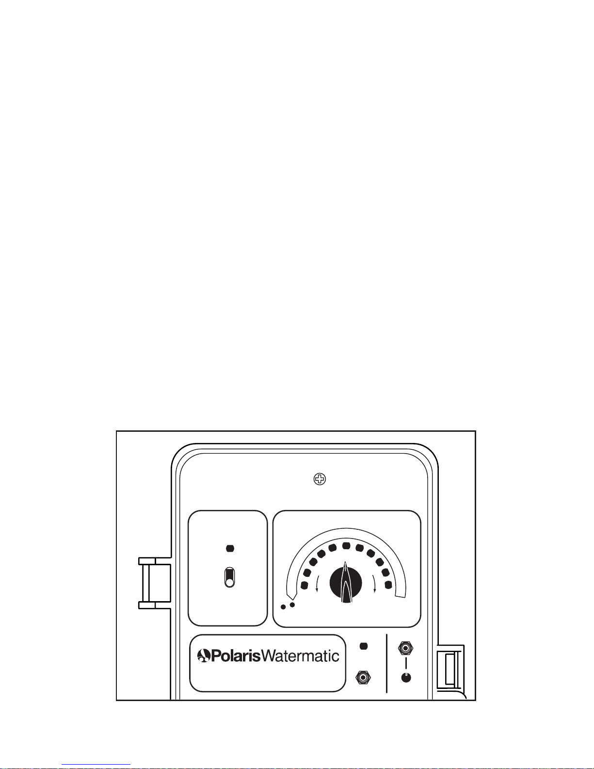
During the filtration cycle of the pool or spa, the sanitizer level
and pH balance are maintained by a constant measurement of
the ORP (Oxidation-Reduction-Potential) and pH balance of
the water. Levels are displayed on the controller’s ORP and pH
light bar arrays (see Figure 1).If the sanitizer level (ORP) falls
below a predetermined set point, the controller activates the
chemical feeder until the preset level is reached.The pH is
maintained in a similar manner.
Figure 1
Page 4

3
II. Specifications
pH Range: 7.0 - 8.2
ORP Range: 100 mV to 1000 mV
Input Power: 24 VAC 50/60 Hz, 40 Volt Amp
(transformer included)
Controller Power: Less than .5 Amp internally fused
Output Power: 24 VAC 50/60 Hz, 5 Amp fuse
Display: Light Bar Array — Yellow for ORP,
Green for pH
Operating
Temperature: 40°-120° F
Sensors: ORP: platinum combination with 10'
cable; pH: glass combination
with 10' cable
Selectable Features:
• Desired ORP settings
• pH calibration
• Safety lockouts for low or high (out of range) ORP levels
• Visual alert and optional audible aler t for self-correcting and
non-correcting conditions
III. Components
The C316 Controller box contains:
• C316 Controller
• ORP Sensor (part #3-270)
• pH Sensor (part #3-260)
•110 V to 24V Plug-in Transformer (part #9-620)
• 1/2" Jaco Compression Fittings (part #2-260)
Recommended (optional) components include:
• Flow Cell Assembly (part #9-700)
Page 5
4
IV. Pre-installation
Before installing the controller, it is impor tant to do a site
assessment and consider where and how you will mount the
unit.The controller should be mounted on a wall or other surface at least ten feet away from the edge of the water and less
than six feet from the GFCI power source.
Once the best site is selected, obtain all necessary mounting
screws or anchors (no mounting screws are provided with
controller). Seal-tight or strain relief connectors for the electrical
access holes in the control box and electrical wire will also
be needed.
A. Timed Feeds
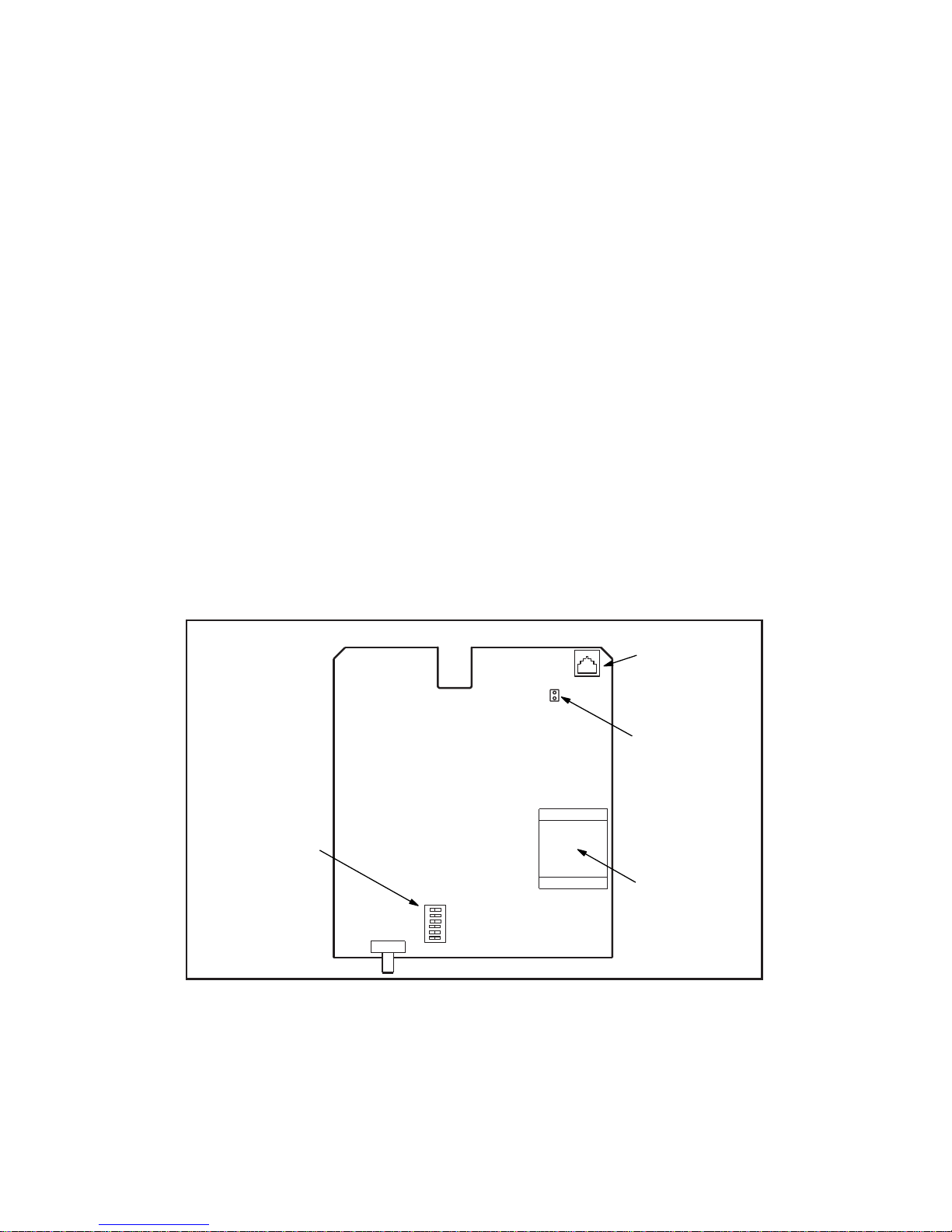
The controller was designed with the flexibility to be adjusted
to meet individual user applications. Feed times and aler ts can
be adjusted through optional dip switch settings.To access and
adjust the dip switches, located on the back of the board (see
Figure 2), disconnect the controller from the power source and
remove the three mounting screws.
The timed feed and delay option allows the use of erosion feeders on spas and small bodies of water without spiking. An automatic shut down feature that can be adjusted for small pool/spa
applications. Additionally, the timed feed allows the injection of
sanitizer before the ORP/pH sensors.
Pool Spa
For Remote
Monitoring
Flow Jumper
Transformer
OFF ON
1
2
3
4
5
6
Dip Switches
Figure 2
Page 6
5
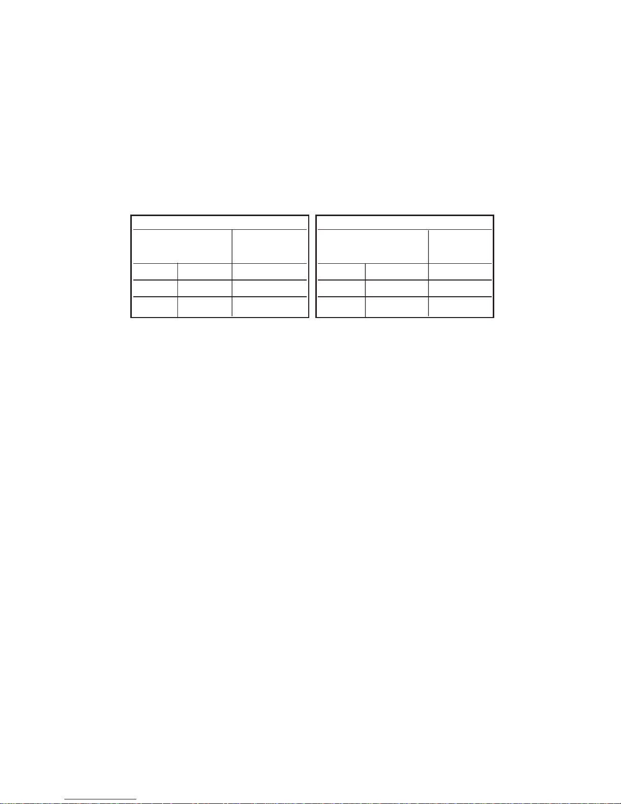
B. Switch Settings
1. Dip switches #1 and #2 control the feed times. Feed times
vary depending on whether the controller is in the pool or
spa mode.
Note: Once the settings have been modified, move the
Pool/Spa Switch on the front of the controller to the appropriate mode to activate the changes. Refer to Figure 4.
2. Dip switch #3 controls the delay time between feeds.
OFF 30 sec.
ON 7 min.
3. Dip switch #4 must be in the OFF position.
4. Dip switch #5 controls the low ORP shutoff.
The controller is set to shut down when the ORP level drops
below 100 mV.This prevents overfeeding if there is an ORP
sensor failure.
Moving switch #5 to the OFF position will override this
function.This override might be required in extremely small
bodies of water where sudden organic loads dissipate the
sanitizer in a very short time.
5. Dip switch #6 has no assigned function.
Pool Position
Dip Switch Feed
12 Time
OFF ON 1 min.
ON ON 5 min.
OFF OFF 10 min.
Spa Position
Dip Switch Feed
12 Time
OFF OFF 1 sec.
ON OFF 5 sec.
OFF ON 10 sec.
Page 7
6
V. Installation
The feeder should be installed before the controller.
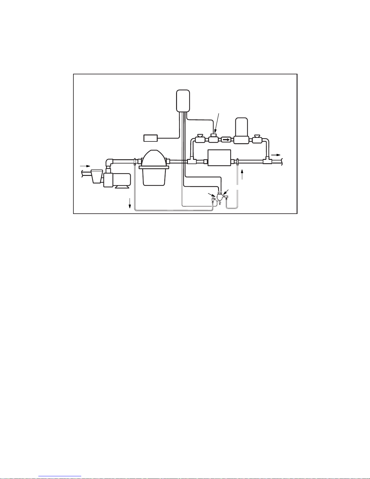
A. Feeding System
Install the feeding system as shown in Figure 3 or in accordance with the installation instructions that were provided with
the feeder.
B. Controller Installation
The voltage on the feeder solenoid valve must match the output
voltage of the controller. The C316 Controller must be matched
with a 24V solenoid valve.
1. Turn off the power to the filter pump at the breaker box.
2. Remove the Caution Plate at the bottom of the controller by
removing the two screws.
3. To avoid damage, remove the controller module from the
controller box by removing the BNC connector(s) and the
faceplate screws.
4. Drill or cut out the electrical access holes that are best
suited for your installation (using a hammer can damage the
controller). Install seal-tight or strain relief connectors in the
access holes and replace the module.
5. Mount the controller on a wall or surface within eight feet of
the feeder.
316
Controller
110V to 24V Plug-in
Transformer
To Pool
Heater
pH Sensor
Filter
Pump
From Pool
Flow
Flow
Switch
Flow Cell
Check
Valve
24V Solenoid
Valve
Figure 3
Page 8
7
6. A plug-in 110v to 24v transformer (part #22-3190) is
provided with the controller. Locate the nearest 110V
standard outlet. Using a minimum of 20 to 22 gauge PVC
jacketed wire, connect the controller to the transformer that
will plug into the 110V outlet.Thread the wire through the
controller seal-tight or strain relief connecter and hook it to
the line side of the terminal strip and transformer.
6. Connect the controller output using a minimum of 20 to 22
gauge wire through the compression fitting to the solenoid.
7. Replace the Caution Plate at the bottom of the controller.
8. We recommend that the sensor be installed in the Flow Cell
Assembly (part #9-700), available from Polaris.
If you do not use the flow cell assembly, you can install the
sensor using the compression fitting that comes with the
controller.The fitting should be installed in a vertical position
on the pressure side of the pool circulation system. It should
be located after the filter and before the heater, and it can
be installed using a tee, saddle tee or a 1/2” NPT tap.
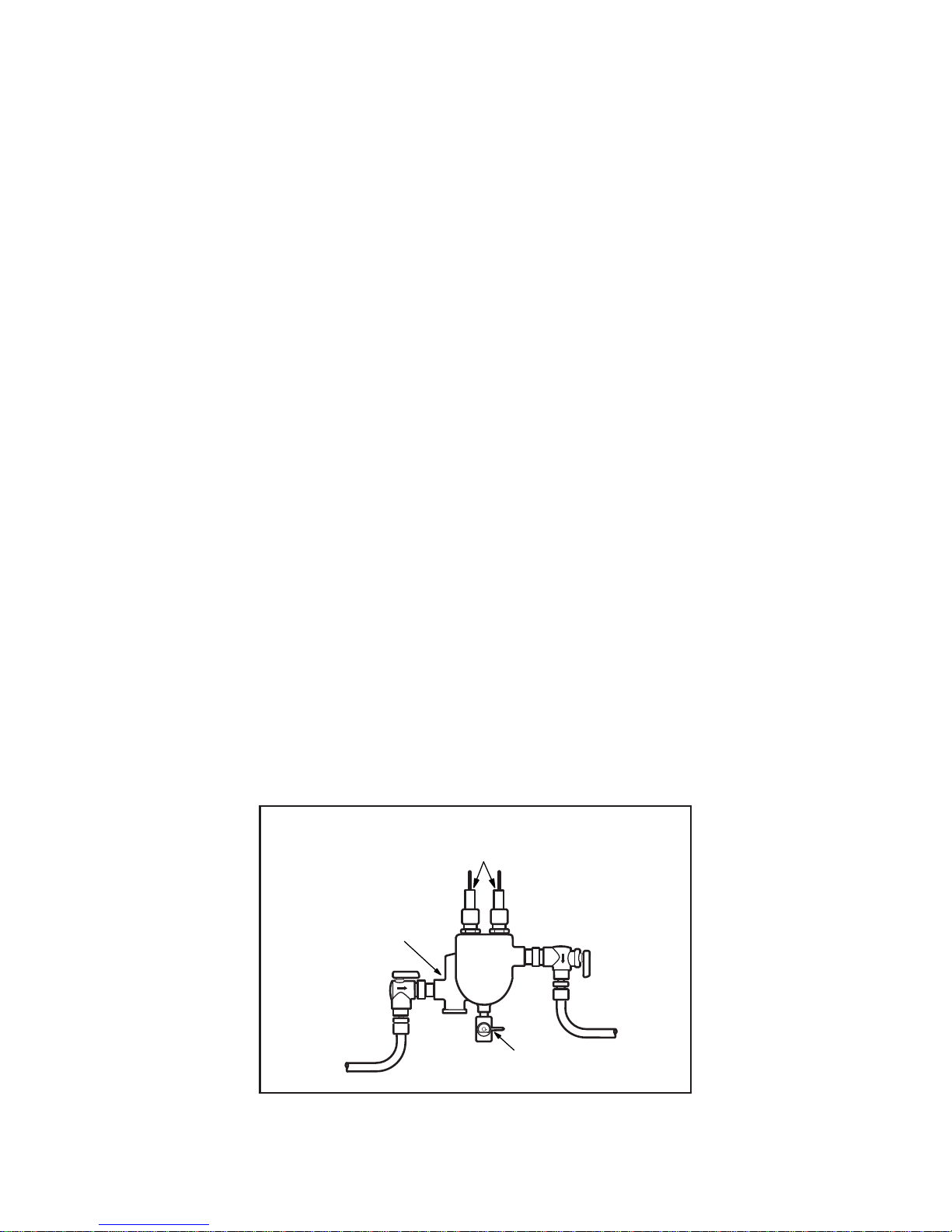
C. Flow Cell Assembly Installation (Optional)
If using the flow cell assembly, locate the assembly within eight
feet of the controller and mount it using the brackets provided.
The flow cell must be plumbed so the pressure difference
between the inlet and outlet is sufficient to ensure flow through
the flow cell. It is also desirable to have filtered water pass over
the sensors to minimize cleaning.
Flow Switch/
Flow Indicator
Sample
Port
Inlet
Ball
Valve
Outlet
Compression Fittings
with Sensors
Flow Cell
Assembly
Page 9
8
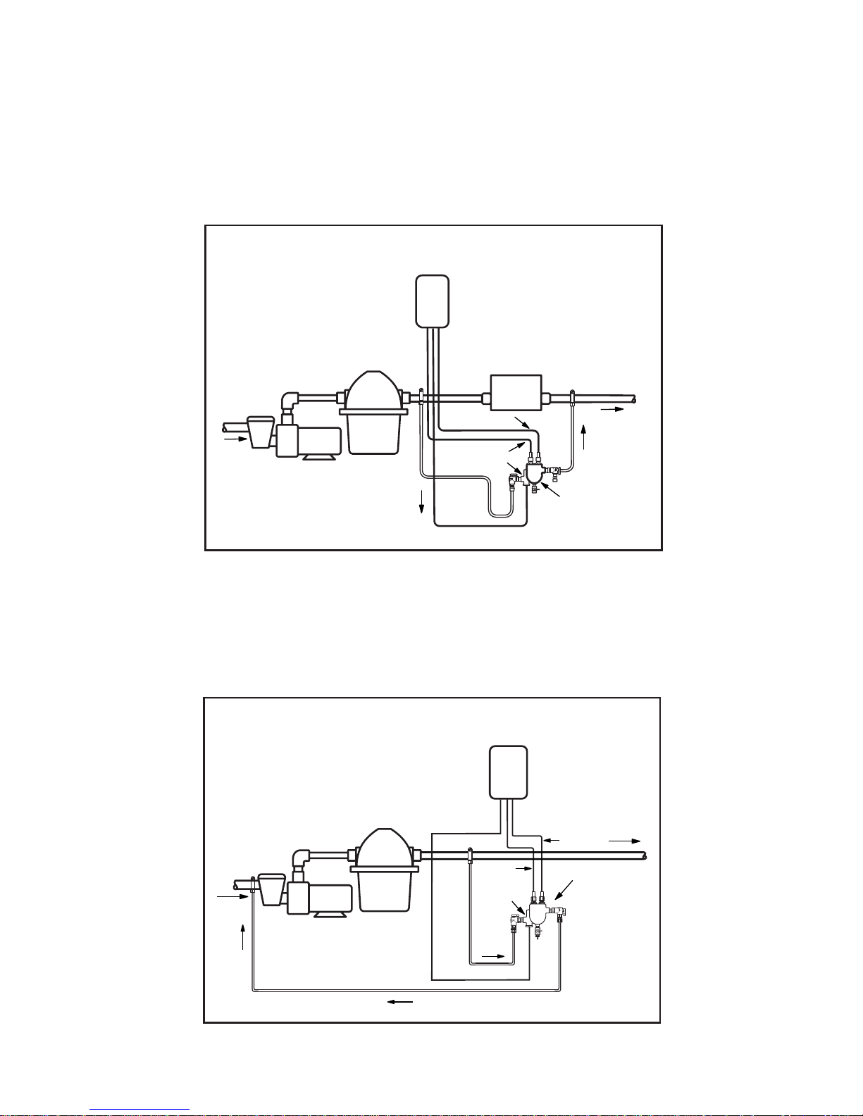
There are three suggested methods to install the flow cell.
1. Plumb the inlet to the flow cell after the filter and plumb the
outlet of the flow cell after the heater using the saddle
clamps provided. See the Pressure Differential Installation
diagram. Fittings for 1/4" NPT taps are included.
2. Plumb from after the filter to before the pump. This ensures
excellent flow but the flow will need to be adjusted so the
sensors are not subjected to a suction environment. See the
Pressure Suction Installation diagram. Open the sample
port (see Flow Cell Assembly drawing) to verify that the
water is flowing freely.
To Pool
From Pool
Flow
Flow
Cell
pH Sensor
ORP Sensor
Filter
Heater
Pump
Controller
Flow Switch
pH
Controller
To Pool
Flow
Flow
Switch
ORP
Flow Cell
From Pool
Flow
Filter
Pump
Pressure Differential
Installation
Pressure Suction
Method
Page 10

9
3. Plumb from before the filter to after the heater, using an
inline filter to minimize debris coming into contact with the
sensors. See the Pressure Differential Alternative
Installation diagram.
Note: Solar systems and other factors can alter pressure
differentials in a system, adversely impacting flow through the
flow cell.
Controller
To Pool
Heater
pH Sensor
Filter
Pump
From Pool
Flow
Flow
Switch
Flow Cell
1/8
NPT
Strainer Assembly #8-110
Pressure Differential
Alternative Installation
Page 11

10
The flow cell comes fully assembled in the box. It is setup to
use with the 3/8" tubing provided; however, other sized tubing or
1/2" hard plumbing can be used.To use alternative tubing,
remove the 90° on/off valves and plumb according to the application.
1. If using a saddle clamp, drill a 7/16" hole in the pipe on
the pressure side of the pump.Thread the 1/8" Jaco fitting
(#2 in diagram below) through the clamp (#3) and place the
nylon jam nut (#4) onto the Jaco fitting.Slide the pipe seal
washer (#5) onto the end of the Jaco fitting.Inser t the completed assembly into the hole in the pipe and tighten the
clamp. Test for leaks.
If the pipe is larger than 2" in diameter, two clamps joined
together will be required per each hole.
If using a pipe tap, drill a 7/16" hole and tap a 1/4" NPT
hole. Apply RTV silicone, teflon stick or teflon paste to the
threads on the Jaco fitting and screw securely into the pipe.
Test for leaks.
2.. Cut the tubing (#1) to the appropriate length. Slightly loosen
the Jaco fitting in the pipe and insert the tubing into it. Take
the free end of the tubing and insert it into the Jaco fitting
on the flow switch side of the flow cell.
3. Complete these steps for the return side of the flow cell.
Use the appropriate remaining par ts to complete this task.
Take the free end of the tubing and insert it into the Jaco
fitting on the outlet side of the flow cell.
1
5
3
2
4
Page 12

11
D. Sensor Installation
Carefully unpack the ORP and pH
sensors and remove the plastic protective cap(s) from the sensor tip(s).
Store the protective cap(s) inside
the controller enclosure for future
use when winterizing or reshipping.
Slide the sensor inside the compression fitting on the flow cell assembly
or the main pool line so that the
sensor tip is below the water line in
the pipe.Tighten the nut of the compression fitting until it is finger tight.
DO NOT USE A WRENCH.
Attach the sensor connector(s) to
the proper fittings on the controller
box. (see Figure 4, #7 and #14).
E. Electrical
Use the plug-in transformer provided to attach to the 110V outlet. Low voltage (24V) wiring can be run from the transformer
output to the controller input. Low voltage wiring can then be
run from the controller output to the 24V solenoid valve.
F. Start-up Operations
1. Determine the free sanitizer level of your swimming pool or
spa using a DPD test kit. It should be between 1.0 and 3.0
ppm—adjust if required.
The controller will not operate if the sanitizer level is below
0.2 ppm (below 100 mV).
2. Check the pH level of your pool or spa with a test kit. The
pH should be maintained between 7.2 and 7.6 to maximize
sanitizer efficiency and ensure the accuracy of the controller.A pH level above or below this range will cause
inaccurate sensor readings. High or low pH levels can also
cause irritation to swimmers as well as other problems
associated with the pool and equipment.
Coil Extra
Sensor Cable
Externally
Controller
Sensor
Compression
Fitting
PVC Tee
Sensor Tip
Page 13

12
3. Make sure the power switch (Figure 4, #2) is off and the
ORP selection knob (Figure 4, #9) is rotated counterclockwise to the lowest setting.
4. Turn on the filter pump and then the controller power switch.
The red power light (Figure 4, #1) and indicator lights on the
controller light bar array (Figure 4, #8) will come on.
5. Leave the system running for approximately five minutes so
the sensors can get an accurate reading from the pool.
6. Check for leaks and correct as necessary.
G. Sanitizer Settings
Be careful when adjusting the ORP set knob.The dial is
extremely sensitive in the 600 to 800 mV range and an adjustment of 50 mV could change the sanitizer level by several parts
per million.
1. The average pool should have a sanitizer level between
1.0 and 3.0 ppm.This equates to approximately 650 mV on
the controller’s ORP light bar array. If the pool has been
balanced correctly, the lights illuminated on the ORP light
bar array should be near 650 mV. Adjust the ORP selection
knob to point at the illuminated light on the ORP light bar
array. If more than one light is illuminated, set the knob to
point in between the two lights.
To maintain a higher sanitizer level, set the selection knob
above the light shown on the light bar array.To maintain a
lower sanitizer level, set the selection knob below the light
shown on the light bar array.
2. Allow the system to operate for 24 hours.
3. With the filtration system running, retest the sanitizer level
using a test kit and adjust the sanitizer selection knob if
necessary. It may require two to three days to accurately set
the controller to maintain the ideal sanitizer level.
4. If the chemistry of the pool or spa water changes (e.g. refill-
ing, significant changes in pH, build-up of total dissolved
solids, additions of other chemicals, etc.), the sanitizer
selection knob may have to be adjusted.
Page 14

13
H. pH Calibration
1. Take a clean sample of pool water and place the pH sensor
into the water sample.
2. Push the pH display button (Figure 4, #10).The yellow ORP
lights on the scale indicator light (Figure 4, #3) will go out
and the green pH scale indicator lights will come on.The
lights on the light bar array now correspond to the readings
on the pH scale.
When the button is pushed, the controller will monitor the
pH for approximately 5 seconds, or for as long as the pH
button is held down, before retur ning to the ORP scale.
3. The pH can be calibrated to match the reading taken by
the test kit by simultaneously holding down the pH display
button and turning the pH calibration set knob (Figure 4,
#11) until the lights on the light bar array indicate the pH
reading of the test kit.
Sanitizer can now be added to the feeder.See the feeder
owner’s manual for instructions.
Page 15

14
VI. Panel Features
# DESCRIPTION FUNCTION
1Power On Light Indicates controller is on
2Power On/Off Switch Turns on the controller
3 Scale Indicators Indicates which scale is being displayed
4Feed Light Flashes during feed cycle; lit during delay
5 Manual Feed Button Instantly feeds sanitizer
6Terminal Strip 24 volt input/output
7 ORP Sensor Connector BNC jack
8 Light Bar Array Displays the ORP or pH sensor readings
9 ORP Set Knob Selects the desired ORP level of the water
10 pH Display Button Displays the pH reading for 10 seconds
11 pH Adjustment Knob Calibrates pH sensor
12 Pool/Spa Switch Selects applicable delay cycles
13 Fuse Adjust to match feeder solenoid
14 pH Sensor Connector BNC jack
15. Output 24V to solenoid valve
16 Input 24V to controller
SPA
POOL
LINE
OUTPUT
POWER
ON
OFF
MAINTAIN
PROPER pH
FEED
MANUAL
pH
ADJ.
FEED
C-316 ORP Controller w/pH Display, 24 V
1.5 AMP SLO-BLO
HOT COM. GND HOT COM. GND
F
U
S
E
F
U
S
E
F
U
S
E
6
.
6
6
.
8
7
.
0
7
.
2
7
.
4
7
.
6
7
.
8
8
.
0
8
.
2
8
.
4
¥
2
0
0
¥
3
0
0
¥
4
0
0
¥
5
0
0
¥
6
0
0
¥
7
0
0
¥
8
0
0
¥
9
0
0
¥
1
0
0
0
¥
1
0
0
D
E
C
R
E
A
S
E
¥
I
N
C
R
E
A
S
E
O
R
P
p
H
12
6
1
2
3
8
9
10
11
4
5
13
14
7
15
16
Figure 4
Page 16

15
VII. Operation
The controller will only operate during the filtration cycle.
A. Setting Feed and Delay Times
1. The controller is preset at the factory with the following feed
and delay times:
Pool Setting:Feed = 1 minute, Delay = 30 second
Spa Setting:Feed = 10 seconds, Delay = 30 seconds
These settings can be adjusted as needed to maintain the
pool balance. To modify the factory settings see PreInstallation, section B.
2. Delays are built into the system to prevent the feeder from
oversanitizing the pool. Once the feeder has dispensed a
dose of sanitizer, the feeder is unable to dispense again for
either 30 seconds or seven minutes.This delay allows the
sanitizer to be circulated through the pool or spa and
returned through the filtration system where the sensors can
test the sanitizer level. After the delay period, another dose
of sanitizer will be dispensed if needed.
B. Feed Light Activation
1. The yellow feed light (Figure 4, #4) flashes to indicate that
the feeder is active and sanitizer is being dispensed. During
feed delays, although no sanitizer is being dispensed. the
feeder is still technically active, so the feed light remains
constantly lit.
2. Do not adjust the set knob while the feed light is on.When
the feed light is on, the lights on the light bar array may
register an inaccurate sanitizer level since the system is still
circulating a dose of sanitizer.
Page 17

16
C. Out-of-range Alert
When the ORP is out-of-range (less than 100 mV) for ten consecutive minutes, the lowest red light on the light bar array will
flash and the controller will not activate the feeder.Depending
on the level of ORP, the manual feed button may be used to
raise the ORP level.
D. Manual Feed
The manual feed button is mainly used to restart the feed cycle
when the system shuts down because the ORP level dropped
below 100 mV (commonly due to an empty feeder or dirty sensor). It can also be used to test the solenoid. It cannot be used
while the feed light is on, i.e.the feeder is active or in delay.
E. Winterizing
If the system is subject to extended shutdowns or is located in
colder climates, it is important to winterize the system.
1. Turn off the main power to the controller.
2. Remove the sensors from the compression fittings.The
sensor tips must be stored in a protective cap or bottle
filled with a liquid solution of one teaspoon salt and
three teaspoons water. Mix the solution thoroughly and
make sure the solution completely covers the sensor tips.
STORE SENSORS IN A WARM PLACE - DO NOT
SUBJECT SENSORS TO FREEZING TEMPERATURES.
3. Empty the system of all water.
4. If the pool or spa has a flow cell assembly installed, drain
the water from the assembly.
5. Remove all material from the feeder and clean all
feeder parts.
Page 18

17
VIII. Maintenance
A. Testing
1. Test the sanitizer and pH levels with a test kit weekly or
more frequently as required by local health codes.
2. Adjust the pH in the pool or spa as needed to maintain a
level between 7.4 and 7.6.
B. Cleaning the Sensor Tips
1. It is important to keep the sensor tips clean to ensure
accurate sanitizer level readings.When the sensor tips
become dirty, the sensors may read lower than actual
sanitizer levels and cause the controller to oversanitize.
Note:A sensor tip coated with scale or oil will not look
visibly dirty.
2. As a general rule, the sensor tips should be cleaned every
two to four weeks for commercial pools and spas, and once
a month for residential pools and spas.Cleaning frequency,
however, can vary from one body of water to another.To
determine the appropriate frequency for your pool or spa,
note the light bar reading prior to cleaning. After cleaning
the sensor, allow a stabilizing per iod of approximately ten
minutes. If the light bar reading is identical to the reading
prior to cleaning, the sensor was not dirty and the time
between sensor cleanings can be increased.
3. To clean the sensor tip, turn off the controller and gently
remove the sensor from the compression fitting.Swirl the tip
for five seconds in muriatic acid (diluted 5 to 1) or white
vinegar, and rinse it in water. DO NOT TOUCH, WIPE OR
BRUSH THE END OF THE SENSOR. For commercial pools
and spas, ever y third cleaning, swirl the sensor tip in a
solution of liquid soap and warm water. Rinse with water.
4. Gently replace the sensors and turn on the controller.
5. Allow the controller to operate for a few minutes to get an
accurate reading. Adjust the selection knob if necessary.
Page 19

18
C. Checking the ORP Sensor
1. The ORP sensor should be checked every six months or
anytime the feeder oversanitizes the water.
2. Clean the sensor tip as noted previously.
3. Place the sensor in a clean glass of tap water. This should
give a reading between 200 and 400 mV. Adding a small
amount of chlorine should cause the ORP level to jump to
between 700 and 800 mV.
If the sensor has been sitting in a high concentration of
chlorine for more than 20 hours, it may pick up a ‘memor y’.
that will not allow it to read below the 500 to 600 mV level.
If this is the case, adjust your controller setting accordingly.
The sensor should return to normal after a week or two
of normal operation.To return it to nor mal functioning more
quickly, place the sensor in a glass of tap water for
72 hours.
4. If the sensor does not respond as indicated, the sensor
should be replaced.
D. Checking the pH Sensor
1. The pH sensor should be checked every six months or
anytime the pH goes out of range or cannot be calibrated to
the test kit.
2. Place the sensor in a clean glass of tap water. Add a small
amount of acid to the glass.The pH reading should drop to
the lowest red light.Then place the sensor in any solution
with a pH above 7.5.The pH reading should move up.
3. If the sensor does not respond as indicated, the sensor
should be replaced.
Page 20

19
IX. Erosion Feeder Operating Tips
•Feeders must be sized properly. When automating an
existing system, multiple feeder may be required.The feeder should be able to attain desired levels in short operating
cycles. Automation becomes ineffective if the feeder must
run for prolonged periods.
• The output of erosion feeders is dependent on the erosion
rate of the tablets.This erosion rate is dependent on the
water flow, contact area on the tabs, and temperature of
the water. Also, bromine tends to erode more slowly
than chlorine.
To maximize output:
1. Fully open all valves into and out of the feeder,.
2. Keep the feeder full at all times.
3. If possible, use small tablets, not large pucks.
• Erosion feeders are designed to maintain levels, not to balance the pool's chemistry. Erosion feeders should not be
used to bring a pool up to the desired levels. Use liquid or
Cal Hypo to raise levels to the desired point. Once the
desired level is reached, the erosion feeder can be used to
maintain these levels.
•Feeders must be located on a separate bypass line with a
check valve between the solenoid valve and the feeder. It
is recommended that a flow indicator be placed in this
bypass line.
• The coil/plunger on the solenoid valve should be
checked periodically for corrosive buildup that could affect
its operation.
• The bypass loop for the feeder may be hooked up from
before the filter to after the heater. If it is, an inline
filter located before the solenoid valve is desirable to prevent debris from entering the solenoid valve.
• Erosion feeders are subject to potting (continued tablet
dissolution when the flow is off). As a result, the sanitizer
concentration in the feeder can be extremely high. When
Page 21

20
the solenoid valve opens, the initial flow from the feeder
may significantly increase (spike) the sanitizer level in a
small body of water. For this reason, it may be desirable to
use the timed-feed feature, which opens the solenoid for a
short per iod, then delays the next feed cycle until the initial
feed is distributed throughout the pool/spa system.
Page 22

21
X.Troubleshooting
PROBLEM POSSIBLE CAUSE SOLUTION
SANITIZER LEVEL Set knob set too low Adjust knob clockwise until the
TOO LOW proper sanitizer level is reached
pH level too low (less than 7.2) Check pH level with a test kit
and adjust as required
Chemical feeder empty Refill chemical feeder
Chemical feeder is clogged Clean and dry feeder measuring
cup assembly
Defective sensor Replace sensor
SANITIZER LEVEL Set knob set too high Adjust knob counterclockwise
TOO HIGH until the proper sanitizer level
is reached
pH level too high (above 7.8) Check pH level with a test kit and
adjust as necessary
Sensor tip is dirty Clean sensor tip
Defective sensor Replace sensor
DISPLAY LIGHTS No power supply Check circuit breaker
OFF
Page 23

22
XI. Guidelines for Using ORP for
Water Maintenance
Q. Why should I maintain a pH level between 7.4 and 7.6?
A. pH levels below 7.4 can cause eye irritation, metal cor-
rosion, etching of plaster, stains, damage to vinyl liners,
and loss of sanitizer. In addition to eye irritation, pH levels above 7.6 can cause cloudy water, scale for mation
and loss of sanitizer efficiency (low ORP).
Q. How do I increase the pH level?
A. Small amounts of basic (alkaline) chemicals such as pH
Plus or pH Up can be added.
Q. How do I lower the pH level?
A. Small amounts of liquid acid (muriatic) or dry acid (sodi-
um bisulfate) such as pH Minus or pH Down can
be added.
Q. How does 650 mV relate to the ppm of chlorine?
A. Pure water, without conditioner, at a pH level of 7.5 cor-
responds to approximately 1.5 ppm of chlorine. Actual
pool or spa water usually takes at least 1-2 ppm of chlo-
rine to generate 650 mV ORP, although the Total
Dissolved Solids and pH can affect the activity of the
chlorine and thus change the level of ORP.
Q. Does an ORP of 650 mV stop algae?
A. No.Because algae is a living organism that adapts
genetically to a constant level of sanitizer, the periodic
addition of an algicide or shocking may be necessary.
Please note that the addition of some chemicals can
change the ORP readings for up to several days.
Q. What causes a low ORP?
A. A low sanitizer level, a pH level above 7.6, a conditioner
level above 200 ppm or a TDS (Total Dissolved Solids)
above 3,000 ppm can all cause a low ORP.
Page 24

23
Q. How do I make sure the ORP sensor is
working properly?
A. Watch the sensor reading when adding sanitizer.If it
does not respond properly, follow the recommended
cleaning procedures, see Maintenance. If cleaning does
not solve the problem, check the sensor as outlined in
the Maintenance section.
Q. How should the ORP sensor respond to adding acid?
A. Adding acid decreases the pH level thus increasing
the ORP.
Q. How should the ORP sensor respond to adding base?
A. Adding base increases the pH level thus decreasing
the ORP.
Q. How should the ORP sensor respond to adding sanitizer?
A. Depending upon the type of sanitizer used, the ORP
should increase. A sanitizer high in base, such as liquid
chlorine (sodium hypochlorite) or a dry chlorine powder
(calcium hypochlorite), however, can cause the pH level
to rise and the ORP to decrease.The pH level must be
in the ideal range to maintain the proper ORP level.
Q. Can ORP be used with ozone?
A. Even though ozone is an excellent oxidizer, it has a
very short lifetime.Therefore, a chlorine or bromine
residual will still be needed in order to maintain the
proper ORP level.When using ozone, the ozone must
be introduced into the system downstream from
the sensors.
Q. Can ORP be used with UV or metal ions?
A. Only if the proper chlorine or bromine residual
is maintained.
Page 25

24
XII.WARRANTY
Polaris Watermatic C316 Controller
This limited warranty is extended to the original consumer
purchaser of this Polaris Watermatic C316 Controller
manufactured by Polaris Pool Systems, Inc., 2620 Commerce
Way, Vista, CA 92083-8438, USA.
Polaris Pool Systems warrants the Water matic Controller it
manufactures, including all parts and components thereof, to be
free of defects in material and workmanship.For questions
regarding your Polar is Watermatic Controller, please feel free to
call or write us. Be sure to provide the serial number of
your unit.
The warranty commences on the date of installation of the controller and shall remain in effect for a period of one (1) year, but
in no event shall it be in effect for more than two (2) years from
the date of manufacture of the controller as established by the
serial number.
This limited warranty does not apply if the failure is caused or
contributed by any of the following: improper handling, improper
storage, abuse, unsuitable application of the unit, lack of reasonable and necessary maintenance, winter freezing or repairs
made or attempted by other than Polar is Pool Systems or one
of its authorized service centers. Polaris will repair or replace, at
its option, a unit or part proved to be defective within the warranty period and under the conditions of the warranty.
Unless local repair is authorized, the consumer must deliver or
ship the unit or the warranty parts, freight prepaid to the nearest
Polaris Author ized Ser vice Center or return it freight prepaid
(after proper authorization) to the plant of manufacture.
Authorization to return a unit to the plant of manufacture must
be obtained from the Polaris Customer Service Department.
For your convenience, please check with your dealer for the
local procedure before exercising this warranty. If fur ther directions or instructions should be required, contact the Customer
Service Depar tment at 1-800-VAC-SWEEP (USA and Canada
only) or 760-599-9600. Be sure to insure your shipments
against loss or damage during transit.
Page 26

25
Polaris is not responsible for the cost of removal of the unit,
damages due to removal, any other expenses incurred in shipping the unit or parts to or from the factory or its author ized
service centers, the installation of the repaired or replacement
unit.The consumer must bear these expenses.
This warranty does not cover repair or replacement of a unit
except at our factory or a Polaris Authorized Service Center.
THIS LIMITED WARRANTY IS IN LIEU OF ALL OTHER WARRANTIES, EXPRESS OR IMPLIED, INCLUDING THE IMPLIED
WARRANTIES OF MERCHANTABILITY AND FITNESS FOR A
PARTICULAR PURPOSE, AND ALL SUCH OTHER WARRANTIES ARE DISCLAIMED EXCEPT TO THE EXTENT ANY
IMPLIED WARRANTY MAY BE IMPOSED BY STATE CONSUMER LAW. ANY SUCH IMPLIED WARRANTY IMPOSED
BY STATE CONSUMER LAW IS LIMITED IN DURATION TO
ONE (1) YEAR FROM DATE OF PURCHASE.
IN NO EVENT SHALL POLARIS POOL SYSTEMS BE LIABLE
FOR INCIDENTAL OR CONSEQUENTIAL DAMAGES OF ANY
NATURE OR KIND OR FOR DAMAGES TO PERSONS OR
PROPERTY, INCLUDING ANY DAMAGE RESULTING FROM
THE USE OF THE POLARIS WATERMATIC CONTROLLER.
Some states do not allow limitations on how long an implied
warranty lasts, or the exclusion or limitation of incidental or
consequential damages, so the above limitations may not apply
to you.
This limited warranty is valid only in the United States of
America and Canada, and it does not apply to Polaris
Watermatic Controllers sold or installed in any other country.
Page 27

© 2003 Polaris Pool Systems, Inc. All rights reserved TL-413 1/03
 Loading...