

Page 1

Page 2

Page 3

California Proposition 65 Warning
This product contains or emits
chemicals known to the state of
California to cause cancer and birth
defects or other reproductive harm.
Page 4

We’ve created a web site just for YOU!
S Technical tips
S New product introductions
S Event schedules
S Parts and Service Manual information
S Exciting details about The Way Out
Check it out...
www .victory-usa.com
Page 5

Page 6

The text, photographs and illustrations used in this manual are based on the most current product information
available at the time of publication. Product improvements or other changes may result in differences between this
manual and the motorcycle. Polaris Industries reserves the right to make production changes at any time, without
notice and without incurring any obligation to make the same or similar changes to motorcycles previously built.
2008 OWNER’S MANUAL
Vegas
®
Kingpin
®
Vegas Lowt
Vegas 8-Ball t
P/N 9921239
VICTORY Motorcycle Division, Polaris Industries Inc.
2100 Highway 55, Medina, Minnesota 55340 -9800 Phone: 1-888-704-5290
CopyrightE 2007 Polaris Sales Inc. All rights reserved.
POLARIS, POLARIS THE WAY OUT, FREEDOM, VEGAS, KINGPIN and VICTORY MOTORCYCLES
VEGAS 8-BALL, VEGAS LOW and KINGPIN 8-BALL are trademarks of Polaris Industries Inc.
DUNLOP is a registered trademark of Dunlop Tire Corporation. LOCTITE is a registered trademark of LOCTITE Corporation.
Features of VICTORY motorcycles are covered by U.S. Patent Nos.:
6,976,691; 6,407,663; D489670; D482311; D482304; D481980; D481973; D474142
are registered trademarks of Polaris Industries Inc.
Kingpin®Tour
Kingpin 8-Ballt
1
Page 7

FOREWORD
Thank you for choosing a Polaris VICTORY motorcycle!
Some of the photographs and illustrations used in the manual are generalizations, so your model may be slightly
different than what is shown.
If you misplace or damage your owner’s manual, you should purchase a replacement copy from an authorized
VICTORY dealer. This manual should be considered part of the motorcycle, and it should remain with the
motorcycle when it’s sold.
If you have questions about the operation or maintenance of the motorcycle after you’ve read this manual, please
contact an authorized VICTORY dealer. To locate the nearest authorized VICTORY dealer, call 1-800-POLARIS
and provide the area code or zip code of your location. Visit www.polarisindustries.com for a listing of authorized
VICTORY dealers by state, zip code or area code.
Your authorized VICTORY dealer will resolve all issues regarding your motorcycle. If you’re not satisfied with the
performance of your VICTORY dealer, please contact the Polaris Consumer Service Department at 1-888-704-5290.
In Canada, call 204-925-7100.
VICTORY motorcycles comply with all federal, state and local safety and emission regulations for the area of
intended sale.
2
Page 8

TABLE OF CONTENTS
FOREWORD 2.......................................................................
INTRODUCTION 4....................................................................
SAFETY 5...........................................................................
REPORTING SAFETY DEFECTS 30....................................................
COMPONENT IDENTIFICATION 31.....................................................
INSTRUMENTS, FEATURES AND CONTROLS 39........................................
PRE-OPERATION CHECK 50..........................................................
OPERATION 67......................................................................
MAINTENANCE 81...................................................................
MAINTENANCE RECORD 86..........................................................
CLEANING 144.......................................................................
STORAGE 150.......................................................................
WARRANTIES 154....................................................................
SPECIFICATIONS 164.................................................................
IDENTIFICATION NUMBERS 169.......................................................
INDEX 170...........................................................................
3
Page 9

INTRODUCTION
Read the Owner’s Manual
Your VICTORY owner’s manual contains information that’s essential to safe riding and proper maintenance of the
motorcycle. Anyone who uses the motorcycle (operators and passengers) must read the owner ’s manual before
riding.
Carefully read and understand the information found in the safety section beginning on page 5. Understand and
follow the procedures in your owner’s manual to keep your VICTORY motorcycle in top condition on the road or in
storage. Bring the manual with you when you ride. Following the precautions and procedures in the manual will
add to your enjoyment and keep you riding safely.
WARNING
Failure to follow the safety precautions and operation and maintenance procedures outlined in this
manual may result in death or injury (to you or your passenger) or damage to the motorcycle.
4
Page 10
SAFETY
Symbols and Terms Used in the Owner’s Manual
The following safety signal words and symbols appear throughout the owner’s manual. Your safety and the safety of
others are involved when these words and symbols are used. Become familiar with their meanings before reading
the manual.
! The safety alert symbol indicates a potential for personal injury to you or others.
WARNING
The safety alert warning indicates a potential hazard that could result in serious injury or death.
Caution
The safety alert caution indicates a potential hazard that may result in minor personal injury or damage to
the motorcycle.
Caution
A caution indicates a situation that may result in damage to the motorcycle.
Notice A notice highlights important information you must pay attention to.
5
Page 11

SAFETY
Safe Riding Practices
WARNING
Improper use of this motorcycle can result in serious injury or death to you, your passenger and others.
To minimize the risk of injury, read and understand the information contained in this section before
operating the motorcycle. This section contains safety information specific to the VICTORY motorcycle,
as well as information about general motorcycle safety. Anyone who uses the motorcycle (operators and
passengers) must follow these safety precautions.
Motorcycling has inherent risks. You can minimize those risks, but you can’t eliminate them completely. Even if
you’re an experienced motorcycle operator or passenger, read all of the information in this safety section before
operating the motorcycle.
S Your ability to safely operate the motorcycle depends on your judgment and your use of safe riding habits. Take a
rider education course from the Motorcycle Safety Foundation or another qualified i nstructor. The course will
help you develop or refresh your expertise in safe riding habits through instruction and riding. For information on
Motorcycle Safety Foundation rider education courses in your area, call 1-800-446-9227 or visit their homepage
at http://msf-usa.org.
S Read and understand all information in this owner’s manual. It contains safety information specific to individual
components and operations.
S Pay close attention to the motorcycle maintenance requirements in this manual. F or additional information or
assistan ce with t echn i cal services specified in the manual o r required b y mechanical circumstan ces, see t he
VICTORY Service Manual or your authorized VICTORY Dealer.
6
Page 12

SAFETY
Safe Riding Practices
The following design characteristics affect how you should ride the VICTORY m otorcycle:
S Some models are designed for one rider and one passenger. Some models are designed for one rider only. Never
carry a passenger on a vehicle designed for a single rider. Never carry more than one passenger on a vehicle designed for only one rider and one passenger.
S The motorcycle is designed for on-road use. Do not exceed the gross vehicle weight rating (see the specifications
section, beginning on page 164, or the certification label on the steering head). Riding off-road or carrying weight
exceeding the maximum weight rating can make handling difficult, which could cause loss of control.
S In the first 500 miles, operate the motorcycle according to the break-in procedures described on page 68. Operat-
ing the motorcycle without following break-in procedures can result in serious engine damage.
S Some VICTORY motorcycles include saddlebags, a windshield, and a passenger backrest as standard equipment.
To maintain stability, be prepared to reduce the operating speed of motorcycles equipped with these accessories.
7
Page 13

SAFETY
Safe Riding Practices
Follow these general safe riding practices:
S Before each ride, make the checks described in the Pre-Operation Check section beginning on page 50.
Operating the motorcycle without completing the pre-operation check may cause damage to the motorcycle or
result in an accident.
S Until you’re thoroughly familiar with the VICTORY motorcycle and all of its controls, practice riding where
there is little or no traffic. Practice riding at a moderate speed on varying road surfaces and under varying weather
conditions.
S Know your skills and limits, and ride within them.
S Allow only licensed, experienc e d operators to ride your motorcycle, and then only after they have become familiar
with its controls and operation.
S Do not ride when you’re fatigued or under the influence of alcohol, prescription drugs, over-the-counter drugs or
any other drugs. Fatigue, alcohol and drugs can cause drowsiness, loss of coordination and loss of balance. They
can also affect your awareness and judgment.
S If your motorcycle operates abnormally, correct the problem immediately (see the VICTORY Service Manual or
contact your authorized VICTORY dealer). If you continue to operate a motorcycle in this condition, you are
likely to aggravate the initial problem, increase the cost of repairs and threaten your safety.
8
Page 14

SAFETY
Safe Riding Practices
S The most common cause of accidents involving a motorcycle and an automobile is the automobile driver’s failure
to see the motorcycle. Ride defensively, as if you are invisible to other motorists, even in broad daylight. Ride
where you’re clearly visible to other motorists, and observe their behavior carefully, as they may not see or be
aware of you.
S Be especially cautious at intersections, as these are the most likely places for an accident.
S To prevent loss of control while operating the motorcycle, keep your hands on the handlebars and your feet on the
footrests.
S Obey the speed limit and adjust your speed and riding technique based on road, weather and traffic conditions. As
you travel faster, the influence of all other conditions increases, which can affect the motorcycle’s stability and
increase the possibility of losing control.
S Do not move or operate the motorcycle with the steering locked (with accessory lock), as the severely restricted
steering could result in loss of control.
S Reduce your speed when:
- The road has potholes or is otherwise rough or uneven.
- The road has sand, dirt, gravel or other loose substances on it.
- The road is wet, icy or oily.
- The road contains painted surfaces, manhole covers, metal grating, railway crossings or other slippery
surfaces.
9
Page 15

SAFETY
Safe Riding Practices
S Reduce your speed when:
- The weather is windy, rainy or otherwise causing slippery or rapidly changing conditions.
- The traffic is heavy, congested, not allowing sufficient space between vehicles or otherwise not flowing
smoothly.
- You are being passed in either direction by a large vehicle that produces a wind blast in its wake.
S To maximize braking effectiveness, use the front and rear brakes together. Improper braking may cause loss of
control or may not slow the vehicle in time to avoid a collision. Be aware of the following braking facts and practices:
- The rear brake provides 40% of the motorcycle’s stopping power, at m ost.
- Consider road conditions before applying the brakes. When the road is wet or rough, or contains loose or
other slippery substances, apply the brakes gradually.
- Bring the motorcycle to the upright position before applying the brakes, and avoid applying the brakes in a
corner if at all possible. When the motorcycle is leaning through a corner, the amount of traction available
for braking is reduced, increasing the possibility of the tires skidding when the brakes are applied.
S When approaching a curve, choose a speed and lean angle that allows you to pass through the curve in your own
lane without applying the brakes. Excessive speed, improper lean angle or braking in a curve can cause loss of
control.
10
Page 16

SAFETY
Safe Riding Practices
S Ground clearance is reduced when the motorcycle leans. Do not allow components to contact the road surface
when leaning the motorcycle in a curve, as this could cause loss of control.
S Retract the sidestand fully before riding. If the sidestand is not fully retracted, it could contact the road surface
and cause loss of control.
S Do not tow a trailer. Towing a trailer can make the motorcycle hard to handle, which could cause loss of control.
Carrying a Passenger
NOTE: Some models are designed for a single rider only. Single-rider models are not equipped with a passenger seat
or passenger footrests. DO NOT carry a passenger on motorcycles not properly equipped for a passenger.
To carry a passenger safely, do the following:
S Direct the passenger to hold onto you or the seat strap with both hands and to keep both feet on the passenger
footrests. Do not carry a passenger who cannot place both feet firmly on the passenger footrests. A passenger who
is not holding on properly, or who cannot reach the passenger footrests, can shift their body erratically, which can
make the motorcycle hard to handle and cause loss of control.
S If necessary, adjust the rear shock absorber preload according to the instructions on page 100. Improper preload
adjustment can make your motorcycle hard to handle and can cause loss of control.
S Before riding, be sure your passenger knows safe riding procedures. Discuss any safety information unfamiliar t o
your passenger. A passenger who is unaware of safe riding procedures may distract you or make movements that
make the motorcycle hard to handle.
S Adjust your riding style to compensate for the differences in handling, acceleration and braking caused by the
additional weight of the passenger. Failure to do so can cause loss of control.
11
Page 17

SAFETY
Safe Riding Practices
Protective Apparel
To decrease the risk of injury and increase riding comfort, wear protective riding apparel.
S Wearing a helmet can prevent a severe head injury. Always wear a helmet that meets or exceeds established safety
standards. Approved helmets in the USA and Canada bear a U.S. Department of Transportation (DOT) label. In
accidents involving motorcycles, head injuries are the leading cause of motorcyclist fatalities, and statistics
prove that an approved helmet i s the most eff ective protection in preventing or reducing head injuries.
S Wear eye protection. Some state laws require that you wear eye protection. Eye protection reduces the chance that
your vision could be impaired by wind or by airborne particles and objects.
S You and your passenger should wear bright or light colored and/or reflective clothing to improve visibility to oth-
er motorists. A motorist’s failure to see or recognize a motorcycle is the leading cause of automobile/motorcycle
accidents.
S Wear gloves, a jacket, heavy boots and long pants to prevent or reduce abrasions, lacerations or burns should the
motorcycle fall.
S Wear boots with low heels, as high heels can catch on pedals or footrests. The combination of boots and pants
should completely cover legs, ankles and feet, protecting skin from engine and exhaust system heat. The engine
and exhaust system get hot soon after the engine is started and stay hot for about half an hour after the engine is
turned off.
S Do not wear loose, flowing clothing or long boot laces, as they can catch on handlebars, levers or footrests, or
become entangled in the wheels, causing loss of control and serious injury.
12
Page 18

SAFETY
Gross Vehicle Weight Rating (GVWR)
Gross vehicle weight is the total combined weight of the motorcycle, the operator and the passenger. Examples of
calculating GVWR are provided on the following pages.
Do not exceed the motorcycle’s gross vehicle weight rating. Exceeding the weight rating can reduce stability and
handling and could cause loss of control. Refer to the specifications section of t his manual beginning on page 164 or
the certification label on your motorcycle’s steering head for model-specific GVWR information.
S The weight of the motorcycle includes the motorcycle and all of its fluids, any accessories and their contents, and
any additional cargo on the motorcycle.
S The weight of the operator or passenger includes body weight, all apparel and objects in or on apparel.
13
Page 19
SAFETY
X
A
EXAMPLE1:
VEGAS
withnoaccessoriesorcarg
o
GrossVehicleWeightRating:
X
A
EXAMPLE2:
VEGA
VEGAS
withaccessorysaddlebags
.
GrossVehicleWeightRating:
GrossVehicleWeightRating:
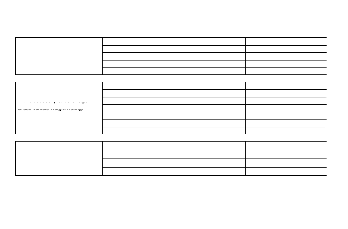
Loading Examples
E
MPLE 1:
with no accessories or cargo.
Gross Vehic le Weight Rating:
1151 lbs (522 kg)
E
MPLE 2:
S
with accessory saddlebags.
Gross Vehic le Weight Rating:
1151 lbs (522 kg)
EXAMPLE 3:
VEGAS LOW
with no accessories or cargo.
1134 lbs (514 kg)
.
Passenger with recommended riding apparel (passenger models) 165 lbs (75 kg)
Passenger with recommended riding apparel (passenger models) 165 lbs (75 kg)
Item Weight
Motorcycle with full capacity of all fluids 686 lbs (311 kg)
Operator with recommended riding apparel 230 lbs (104 kg)
Total Weight 1081 lbs (490 kg)
Item Weight
Motorcycle with full capacity of all fluids 686 lbs (311 kg)
Weight of leather saddlebags and brackets 12 lbs (5.5 kg)
Cargo (saddlebags at capacity) 14 lbs (6 kg)
Operator with recommended riding apparel 230 lbs (104 kg)
Total Weight 1107 lbs (502 kg)
Item Weight
Motorcycle with full capacity of all fluids 679 lbs (308 kg)
Operator with recommended riding apparel 230 lbs (104 kg)
Total Weight 909 lbs (412 kg)
NOTE: As shown in Example 2, the weight of any accessory items (leather saddlebags and the brackets) in addition
to the cargo, must be added to the base weight of the motorcycle. NEVER exceed GVWR. If you have any questions regarding safe loading of your VICTORY motorcycle, please consult an authorized VICTORY dealer.
14
Page 20
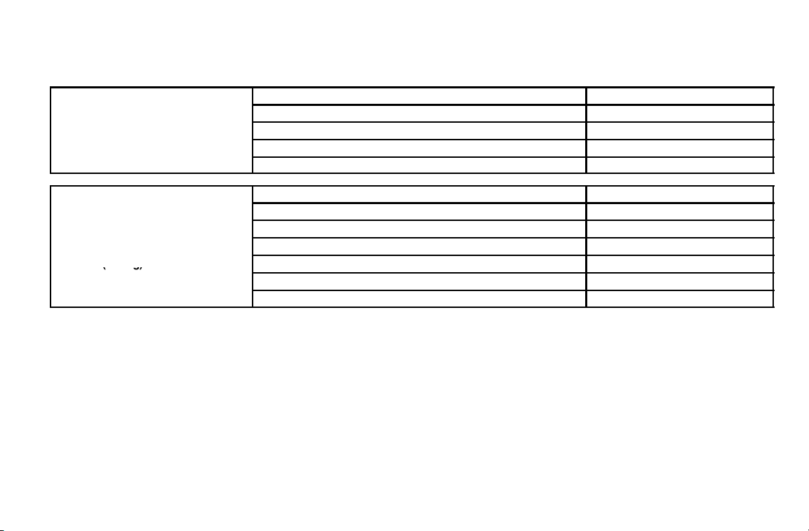
Loading Examples
X
A
EXAMPLE4:
KINGPIN
withnoaccessoriesorcargo.
GrossVehicleWeightRating:
X
A
EXAMPLE5:
KINGPINTOUR
withcargo
.
GrossVehicleWeightRating:
(g)
SAFETY
E
MPLE 4:
with no accessories or cargo.
Gross Vehicle Weight Rating:
1234 lbs (560 kg)
E
MPLE 5:
with cargo.
Gross Vehicle Weight Rating:
1234 lbs (560 kg)
Passenger with recommended riding apparel (passenger models) 165 lbs (75 kg)
Passenger with recommended riding apparel (passenger models) 165 lbs (75 kg)
Item Weight
Motorcycle with full capacity of all fluids 704 lbs (319 kg)
Operator with recommended riding apparel 230 lbs (104 kg)
Total Weight 1099 lbs (498 kg)
Item Weight
Motorcycle with full capacity of all fluids 769 lbs (349 kg)
Cargo (top box at capacity) 20 lbs (9 kg)
Cargo (saddlebags at capacity) 14 lbs (6 kg)
Operator with recommended riding apparel 230 lbs (104 kg)
Total Weight 1198 lbs (543 kg)
NOTE: The weight of any accessory items such as saddlebags and brackets, or individual items in addition to the
cargo, must be added to the base weight of the motorcycle. NEVER exceed GVWR. If you have any questions regarding safe loading of your VICTORY motorcycle, please consult an authorized VICTORY dealer.
15
Page 21

SAFETY
Carrying Cargo
Use the following guidelines when attaching cargo or accessories to the motorcycle. Where applicable, these
guidelines also refer to the contents of any accessories.
S Keep cargo and accessory weight to a minimum, and keep items as close to the motorcycle as possible to mini-
mize a change in the motorcycle’s center of gravity. Changing the center of gravity can cause loss of stability and
handling and result in loss of control.
S Distribute weight evenly on both sides of the motorcycle. Maintain even weight distribution by checking accesso-
ries and cargo to make sure they’re securely attached to the motorcycle before riding and whenever you take a
break from riding. Uneven weight distribution, or accessories or cargo that shift suddenly while you’re riding can
make the motorcycle hard to handle and result in loss of control.
S Do not attach large or heavy cargo such as sleeping bags, duffel bags or tents to the handlebars, front fork area or
front fender. Cargo or accessories placed in these areas can cause instability (due to improper weight distribution
or aerodynamic changes) and can cause loss of control. Such items can also block air flow to the engine and
cause overheating that can damage the engine.
S Do not exceed the maximum cargo weight limit of any accessory (see accessory instructions and labels), and do
not attach cargo to an accessory not designed for that purpose, as these could result in an accessory failure that
could cause loss of control.
S Except for highway footrests, do not attach anything else to the highway bar.
16
Page 22

SAFETY
Saddlebags / T op Box
When operating a motorcycle with original equipment or accessory saddlebags:
S Never ride at speeds exceeding 80 mph (129 km/h). Depending on load and weather conditions, the maximum
safe operating speed may be less than 80 mph (129 km/h). Saddlebags, combined with the lifting or buffeting
effects of wind, can make the motorcycle unstable and cause loss of control.
S Distribute weight evenly in each of the saddlebags.
S Do not exceed the maximum cargo weight limit of the saddlebags.
Accessory leather saddlebags, semi-hard saddlebags, or hard saddlebags = 7 lbs. (3.2 kg) each
Top Box weight capacity (Kingpin Tour) = 20 lbs. (9.0 kg)
S Do not exceed the motorcycle’s gross vehicle weight rating. Exceeding the weight rating can reduce stability and
handling and cause loss of control.
17
Page 23

SAFETY
Modifications
Modifying the motorcycle by removing any equipment or by adding equipment not approved by VICTORY may
void your warranty. Such modifications may make the motorcycle unsafe to ride and could result in severe injury to
operator or passengers, as well as damage t o the motorcycle. Some modifications may also be illegal in some states.
If in doubt, contact your authorized VICTORY Dealer.
Parking the Motorcycle
When leaving the motorcycle unattended, turn the engine off and remove the ignition key. See page 79.
Park the motorcycle where people are not likely to touch the hot engine or exhaust system or place combustible
materials in close proximity to these hot areas. Do not park near a flammable source such as a kerosene heater or an
open flame, where hot components could ignite combustible materials.
Park the motorcycle on a firm, level surface. Sloped or soft surfaces may not support the motorcycle when it’s
parked, and it may tip over. If you must park on a slope or soft surface, follow the precautions outlined on page 79.
18
Page 24
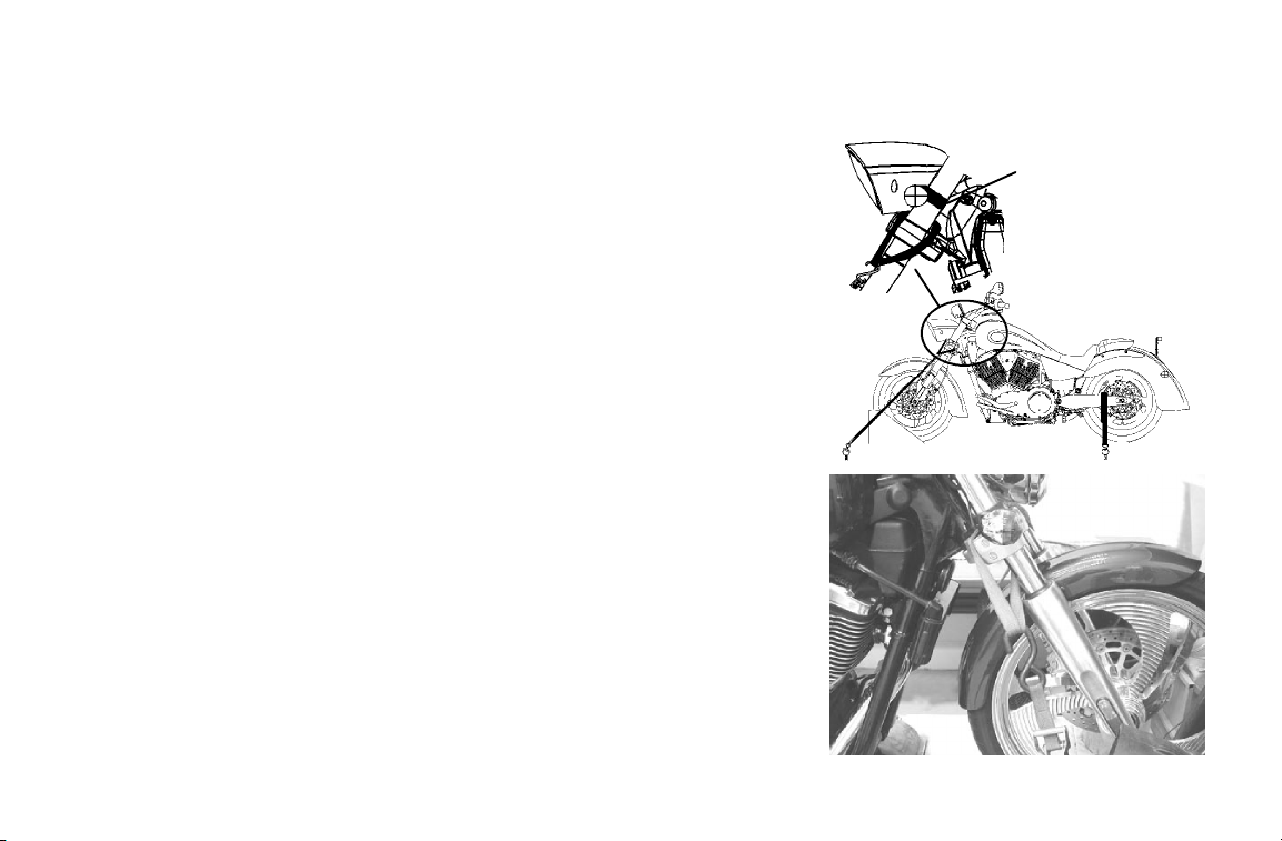
Transporting the Motorcycle
If you must transport the motorcycle:
S Use a truck or trailer. Do not tow the motorcycle with another
vehicle, as towing will impair the motorcycle’s steering and
handling, which can cause loss of control.
S Position and restrain the motorcycle so it remains upright on
the truck or trailer, as gasoline may leak out of the fuel tank if
the motorcycle leans to one side. Gasoline is a fire hazard and
it can also damage the motorcycle’s finish.
S Place the transmission in neutral.
S Do not restrain the motorcycle using the handlebars. Loosen
the front turn signal mounts and slide them up to make room
for the tiedown strap. Place tie-downs around the fork tubes
above the lower triple clamp. Secure the rear of the motorcycle
with tiedowns around the swingarm, being careful to avoid the
brake line, exhaust, and drive belt. Reposition the turn signals
after transportation.
SAFETY
Loosen screw,
slide turn signal up
KINGPIN
VEGAS
19
Page 25

SAFETY
Accessory Selection and Installation
Because VICTORY cannot test and make specific recommendations concerning every accessory or combination of
accessories sold, the operator is responsible for determining that the motorcycle can be safely operated with any
accessories or additional weight. Use the following guidelines when choosing and installing accessories:
S Do not install accessories that impair the stability, handling or operation of the motorcycle. Before i nstalling an
accessory, be sure that it does not
- Reduce ground clearance when the motorcycle is either leaned or in a vertical position.
- Limit suspension or steering travel or your ability to operate controls.
- Displace you from your normal riding position.
- Obscure lights or reflectors.
S Bulky or large accessories can cause instability (due to the lifting or buffeting effects of wind) and loss of control.
S Do not install electrical accessories that exceed the capacity of the motorcycle’s electrical system. Never install
higher wattage light bulbs than those supplied as original equipment. An electrical failure could result and cause
hazardous loss of engine power or lights or damage to the electrical system.
S If you want to add a windshield, backrest or luggage rack, choose one designed and approved by VICTORY spe-
cifically for your model. Follow the instructions for proper installation and use. An improperly designed or
installed windshield, backrest or luggage rack can reduce stability, causing loss of control.
:
20
Page 26

SAFETY
Gasoline and Exhaust
For complete fueling procedures, see page 70.
Gasoline is highly flammable and can be explosive in certain conditions. Observe the following precautions when
you refuel or service the fuel system:
S Turn off the engine.
S Use a well-ventilated area.
S Open the fuel cap slowly.
S Do not spill gasoline on the engine or the exhaust system. Immediately wipe, or rinse with water, gasoline spilled
on any part of the motorcycle or the surrounding area.
S Do not smoke while fueling.
S Do not fuel in an area where there are sparks or open flame.
Gasoline and gasoline vapors are poisonous and can cause severe injury. Do not swallow gasoline, inhale gasoline
vapors, or spill gasoline on yourself or your clothes. If you swallow gasoline, inhale more than a few breaths of
gasoline vapor, or get gasoline in your eyes, see a physician immediately. If you spill gasoline on your skin, wash it
off immediately with soap and water. If you spill gasoline on your clothes, change your clothes immediately.
Exhaust gases contain carbon monoxide, a colorless, odorless gas that can cause unconsciousness or severe injury.
Observe the following precautions to avoid the effects of exhaust gases:
S Do not inhale exhaust gases.
S Do not start or run the engine in an enclosed area.
21
Page 27

SAFETY
Maintenance
Maintain the motorcycle according to the following requirements:
S Before each ride, complete a pre-operation check as outlined beginning on page 50. Operating the motorcycle
without completing the pre-operation check can cause damage to the motorcycle or result in an accident.
S Perform periodic maintenance according to the intervals outlined in the Periodic Maintenance Interval tables be-
ginning on page 82. Operating the motorcycle without performing periodic maintenance can damage the motorcycle or result in bodily injury.
S Maintain proper tire pressure and tread condition and proper wheel and tire balance. Inspect tires regularly and
replace them if they’re worn or damaged. Use only an approved replacement tire and see the VICTORY Service
Manual or your authorized VICTORY Dealer for tire replacement. Operating the motorcycle with improper tire
pressure or tread condition, or improper wheel or tire balance, can make the motorcycle hard to handle and cause
loss of control.
S Check proper steering head bearing adjustment. Regularly inspect the rear shock absorber and the front forks.
Check for fork oil or shock absorber fluid leaks. Operating the motorcycle with a loose, worn, or damaged steering system or front or rear suspension system can make the motorcycle hard to handle and cause loss of control.
To repair steering or suspension system wear or damage, see the VICTORY Service Manual or contact your authorized VICTORY Dealer.
22
Page 28

SAFETY
Maintenance
S Keep the motorcycle clean. In addition to extending the service life and the original appearance of the motor-
cycle, a complete and thorough cleaning can reveal items in need of repair. For complete cleaning procedures, see
page 144.
S Keep equipment required by federal, state, and local laws in place and in good working condition. Your license
plate must be clean, clearly visible i n all conditions, and installed in a position specified by law.
S Each fastener used in the motorcycle meets our quality specifications for strength, finish and type. When replace-
ment fasteners are needed, use only genuine VICTOR Y parts, tightened to the proper torque. A fastener that does
not meet original specifications could fail and result in damage to the motorcycle or injury to riders.
Electromagnetic Interference
This vehicle complies with European directive 97/24/EC Chapter 8 requirements, which is equivalent to Canadian
ICES-002.
23
Page 29
SAFETY
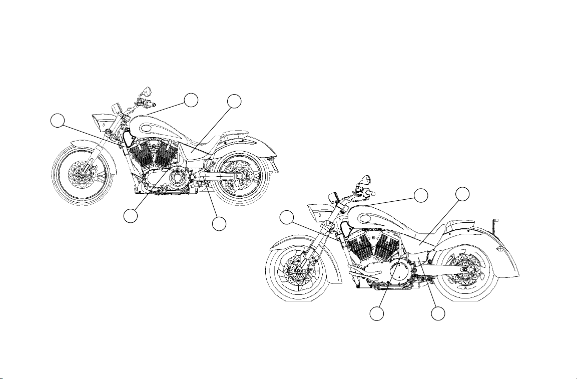
Location of Safety and Vehicle Information Labels (All Models)
See page 25 for decal type and description.
24
A
B
E
D
A
C
B
E
D
C
Page 30
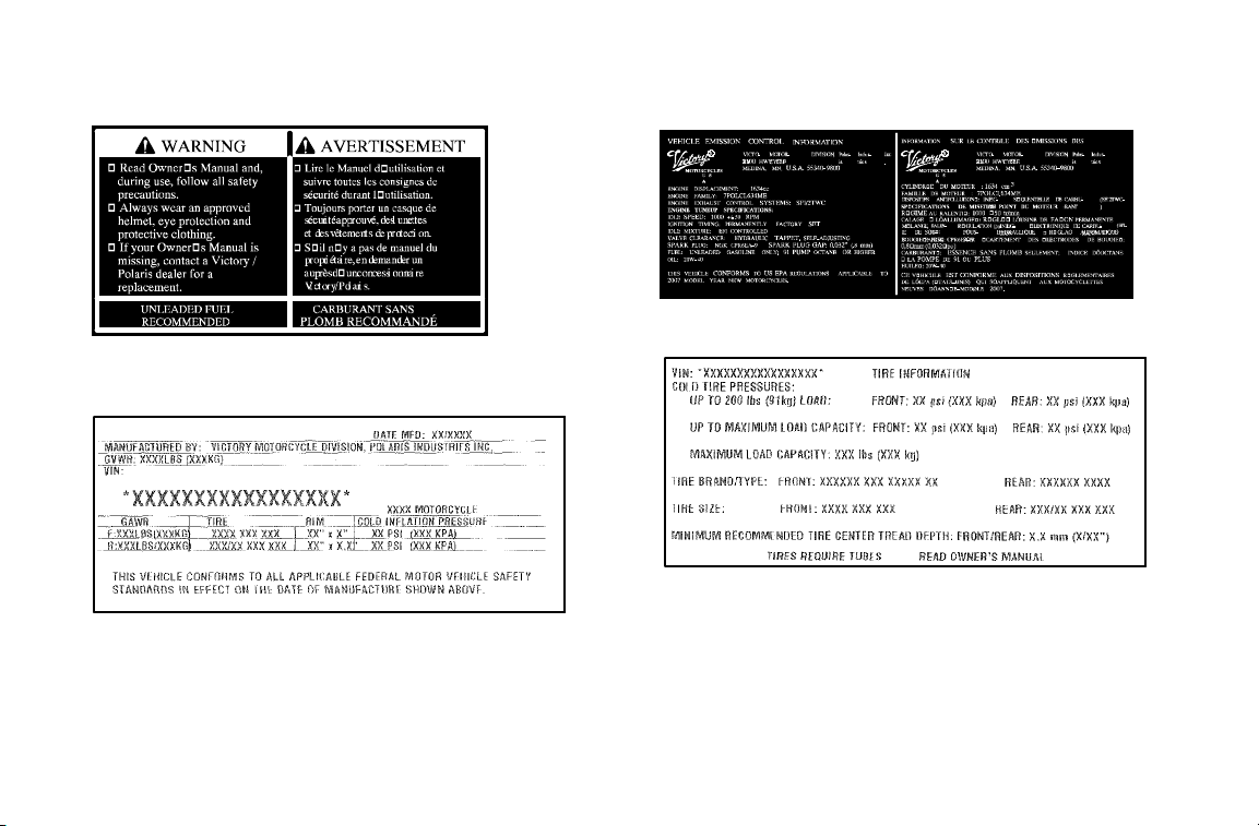
Location of Safety and Vehicle Information Labels (All Models)
Location C (NOISE EMISSION)
Location A (FUEL WARNING)
Location D (TIRE INFORMATION)
(Under Left Side Cover)
Location B (MANUFACTURING INFORMATION)
Information varies by model
Information varies by model
Location E (ENGINE I.D.)
(on right rear crankcase half)
SAFETY
25
Page 31

SAFETY
Location of Safety and V ehicle Information Labels (All Models)
See page 27 for decal type and description.
F
26
Page 32

Location of Safety and Vehicle Information Labels (All Models)
FUSE BOX REMOVAL
Location F
FUSE and RELAY LOCATION
(Under right side cover, on side of fuse box cover)
(on base of fuse box)
SAFETY
27
Page 33

SAFETY
Location of Safety and Vehicle Information Labels (All Models)
See page 29 for decal type and description.
28
I
H
H
G
I
G
Page 34

Location of Safety and V ehicle Information Labels (All Models)
Location G (TIRE SAFETY)
Location H (EMISSION CONTROL INFORMATION)
SAFETY
49 State Models
Catalyst Models Only
Canada Models
Location I (PATENT NOTICE)
Location I (PATENT NOTICE)
(LH Rear of subframe down tube)
(LH Rear of subframe down tube)
Information varies by model
Information varies by model
29
Page 35

SAFETY
Reporting Safety Defects
If you believe that your vehicle has a defect that could result in a crash or cause injury or death, you should
immediately inform the National Highway Traffic Safety Administration (NHTSA) i n addition to notifying Polaris
Industries in writing.
If NHTSA receives similar complaints, it may open an investigation, and if it finds that a safety defect exists in a
group of vehicles, it may order a recall and remedy campaign. However, NHTSA cannot become involved in
individual problems between you, your dealer or Polaris Industries.
To contact NHTSA, or obtain other information about motor vehicle safety, you may either call the Vehicle Safety
Hotline toll-free at 1-888-327-4236 (TTY 1-800-424-9153), visit the NHTSA website at www.safercar.gov, or write
to:
ADMINISTRATOR
NHTSA
US Department of Transportation
400 7th Street Southwest
Washington, DC 20590
30
Page 36

Handlebar Area - VEGAS Models
1. Speedometer
2. Front Brake Fluid Reservoir
3. Right Mirror
4. Throttle Control Grip
5. Front Brake Lever
6. Right Handlebar Switch
7. Indicator Lamps
8. Fuel Cap
9. Left Handlebar Switch
10. Clutch Lever
11. Left Mirror
11
10
COMPONENT IDENTIFICATION
3
1
9
8
2
4
5
7
6
31
Page 37

COMPONENT IDENTIFICATION
Left Side - VEGAS Models
1. Front Fork
2. Front Turn Signal
3. Headlamp
4. Air Filter
5. Spark Plug (2)
6. Ignition Switch
7. Left Side Cover
8. Battery (under side cover)
9. Taillight
10. Rear Turn Signal
11. Rear Axle Adjuster (1 each side)
12. Rear Brake Caliper
13. Passenger’s Foot Rest
(passenger models)
14. Evaporative Canister
(California Models)
15. Engine Oil Filter
16. Engine Oil Drain Plug
(under engine)
17. Sidestand
18. Operator’s Foot Rest
19. Gear Shift Lever
20. Horn
21. Front Brake Caliper
3
2
4
1
21
20
19
17
1616
6
15
5
18
17 13
14
8
7
9
10
12
11
32
Page 38

Right Side - VEGAS Models
1. Drive Belt (under guard)
2. Passenger Seat
(passenger models)
3. Seat Strap
4. Operator’s Seat
5. Side Cover
6. Rear Shock Absorber
(access through RH side cover)
7. Front Turn Signal
8. Front Fork
9. Rear Brake Pedal
10. Operator Foot Rest
11. Engine Oil Fill Cap/Dipstick
12. Rear Brake Fluid Reservoir
(under side cover)
13. Drive Sprocket (under cover)
14. Fuses (under side cover)
15. Diagnostic Connector
16. Passenger Foot Rest (passenger models)
17. Exhaust Mufflers
COMPONENT IDENTIFICATION
10
7
8
9
3
2
1
17
16
15
5
4
6
11
12
1314
33
Page 39

COMPONENT IDENTIFICATION
Handlebar Area - KINGPIN Models
1. Indicator Lamps
2. Front Brake Fluid Reservoir
3. Right Handlebar Switch
4. Right Mirror
5. Throttle Control Grip
6. Throttle Cables
7. Fuel Cap
8. Left Mirror
9. Left Handlebar Switch
10. Clutch Lever
8
9
10
1
2
4
3
5
6
7
34
Page 40

Left Side - KINGPIN Models
1. Front Fork
2. Front Turn Signal
3. Headlamp
4. Speedometer
5. Air Filter
6. Spark Plug (2)
7. Ignition Switch
8. Left Side Cover
9. Battery (under side cover)
10. Taillight
11. Rear Turn Signal
12. Rear Axle Adjuster (1 each side)
13. Rear Brake Caliper
14. Passenger’s Foot Rest
(passenger models)
15. Evaporative Canister (California Models)
16. Oil Filter
17. Oil Drain Plug (on bottom of crankcase)
18. Sidestand
19. Operator’s Foot Rest
20. Gear Shift Lever
21. Front Brake Caliper
21
COMPONENT IDENTIFICATION
19
6
7
8
9
10
11
13
14
15
161718
12
4
3
2
1
5
20
35
Page 41

COMPONENT IDENTIFICATION
Right Side - KINGPIN Models
1. Passenger’s Seat (passenger models)
2. Seat Strap
3. Operator’s Seat
4. Rear Shock Absorber
(access through RH side cover)
5. Side Cover
6. Engine Oil Fill Cap/Dipstick
7. Front Brake Lever
8. Front Turn Signal
9. Horn
10. Front Fork
11. Rear Brake Pedal
12. Operator’s Foot Rest
13. Rear Brake Fluid Reservoir
14. Drive Sprocket (under cover)
15. Fuses (under side cover)
16. Diagnostic Connector
17. Passenger Foot Rest (passenger models)
18. Drive Belt (under guard)
19. Exhaust Mufflers
19
4
2
1
18
17
3
16
56
1415
13
12
7
8
9
10
11
36
Page 42

COMPONENT IDENTIFICATION
Vehicle Identification Number
The vehicle identification number (VIN) is stamped into the front of the steering head and also appears on the
certification label. You will need the vehicle identification number to title, register, license or insure the motorcycle,
or to order replacement parts.
Chassis:
A = VEGAS 8-BALL
B = NESS JACKPOT
C = KIN GPIN
D = N ESS SIGNATURE SERIES KING PIN
E = NESS SIGNATURE SERIES VEGAS
G = VEGAS
H = HAMMER
L = VEGAS LOW
P = KINGPIN 8-BALL
T = TOURING
X = VEGAS JACKPOT
Type:
B = Standard
C=Custom
D=Deluxe
S = Sport
Series:
C = Canada
D = Domestic (49 State)
L = California
U = United Kingdom
Serial Number
*5VPGB26D073000000*
Plant Code
SAE - assigned
World Manufacturing Identifier
Engine Size:
1 = 1507 cc
2 = 1634 cc
Engine HP:
6 = 78-94
Check Digit Model Year:
8 = 2008
37
Page 43

COMPONENT IDENTIFICATION
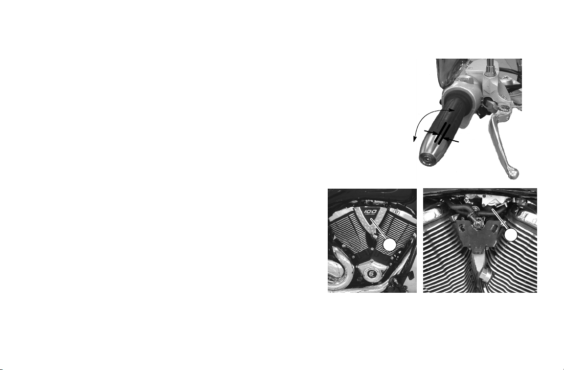
Engine Identification Number
The engine identification number is a combination of the engine model
and serial numbers. The first 8 digits are the engine model number and
the last 5 digits are the serial number.
The engine serial number is stamped into the rear upper portion of the
right crankcase behind the rear cylinder. You may need the engine
identification number to title, register, license or insure the motorcycle,
or to order replacement parts.
Ignition Key Number
The ignition key identification number is stamped into the shaft of
each key .
With the ignition key number and proof of ownership, an authorized
VICTORY dealer can assist you in obtaining a replacement key.
Notice For easy reference, record all vehicle numbers in the space provided on page 169.
38
Page 44

INSTRUMENTS, FEATURES AND CONTROLS
Ignition Key
The ignition key operates the ignition switch and parking lights.
Ignition Switch
The ignition switch energizes the ignition, the lighting system, and all
electrical switches and buttons.
Off Position
In the OFF position, all electrical circuits are inactive and the ignition
key can be removed. Turn the ignition switch to the OFF position and
remove the ignition key when leaving the motorcycle unattended.
On Position
In the ON position, all electrical circuits are energized and the ignition
key cannot be removed. The headlamp, taillight, and instrument lights
illuminate. With the engine stop/run switch set to the RUN position (see
page 46) you can start the engine. You can also activate the emergency
flashers, turn signals and all other electrical features.
Caution
1. Off
2. On
Before starting the engine, read the instructions for starting the engine beginning on page 71.
Park Position (P)
In the PARK position, the taillight, indicator lights, and license plate light illuminate, the emergency flashers can be
activated, and the ignition key can be removed. You must push the ignition key into the switch while selecting the
Park position.
3
2
1
3. P (Park)
39
Page 45

INSTRUMENTS, FEATURES AND CONTROLS
Instrument Cluster
The instrument cluster includes the speedometer, the tachometer
(accessory) and the multi-function display.
1. Speedometer
2. Odometer / Trip Odometer
3. Odometer & Trip Odometer Toggle / Trip Odometer Reset
Speedometer
The speedometer reports current motorcycle speed in miles per hour
(mph) or kilometers per hour (kph), Canada.
Odometer
The odometer display shows total miles traveled in the window on the l ower
portion of the speedometer.
Trip Odometer
A trip odometer is included on the speedometer. The trip odometer shows total miles traveled since the trip
odometer was reset. You can use the trip odometer to calculate your miles per gallon and estimate the number of
miles you can travel on a tank of fuel.
To toggle the display between Odometer and TRIP Odometer, the ignition switch must be in the ON position. Press
the reset button (3). The display changes to “TRIP”.
To reset the trip odometer, the ignition switch must be in the ON position with the display in trip odometer mode.
Press and hold the reset button (3) until the TR IP odometer display resets to zero.
1
2
3
40
Page 46

INSTRUMENTS, FEATURES AND CONTROLS
Tachometer (Accessory)
Some mod els are equ ipped with a tachomet er (1). An accessory
tachometer kit can al so be purchased as an accessory through your
VICTORY dealer. The tachomet er report s current engine speed i n
revolutions per minute (RPM). A red line on the gauge indicates
maximum safe engine RPM. With tachometer installed, the trip
odometer reset button (2) is located on the instrument mounting
plate. S ee page 4 0.
2
WARNING
Do not operate the engine over 5600 RPM. Excessive RPM could cause engine damage or failure that could
result in you losing control of the motorcycle.
Overdrive Indicator Lamp
The overdrive lamp (3) illuminates when O/D (6th gear) is selected
(tachometer-equipped 100/6 engine only).
1
3
41
Page 47

INSTRUMENTS, FEATURES AND CONTROLS
Indicator Lights
Neutral Indicator (1)
The neutral indicator illuminates when the transmission is
in neutral, and the ignition key is ON.
1
Headlamp High Beam Indicator (2)
The headlamp high beam indicator illuminates when the
headlamp switch is set to high beam (see page 44).
Check Engine Indicator (3)
The check engine indicator will illuminate any time the i gnition switch is in the ON position and the engine
control module sensors report abnormal sensor or engine operation. The check engine indicator will
continue to illuminate as long as the fault condition exists. It also illuminates momentarily when the
ignition switch is in the ON position and the engine is not running. This demonstrates that the indicator is
functioning properly.
Caution
If the check engine indicator illuminates while the engine is running, a serious engine problem may exist.
Contact an authorized VICTORY dealer as soon as possible.
3
2
42
Page 48

Indicator Lights
Low Oil Pressure Indicator (4)
The low oil pressure indicator illuminates when engine oil pressure drops below safe operating pressure. If
this indicator illuminates while the engine is running, turn the engine off immediately and check the oil
level. Add oil if necessary. If the oil level is correct and the indicator remains illuminated after the engine is
restarted, turn the engine off immediately.
The low oil pressure indicator also illuminates when the ignition switch i s in the ON position and the engine
is not running. This demonstrates that the indicator is functioning properly.
Turn Signal Indicator (5)
The turn signal indicator flashes when the left, right, or
both turn signals (hazard) are active.
If a turn signal bulb has failed, or if there is a short circuit in
the turn signal system, the turn signal indicator flashes at more
than twice the normal rate.
Low Fuel Indicator (6)
The low fuel indicator illuminates when approximately
0.8 gallons (3.0 liters) of fuel remains in the fuel tank.
INSTRUMENTS, FEATURES AND CONTROLS
6
5
4
43
Page 49

INSTRUMENTS, FEATURES AND CONTROLS
Left Handlebar Controls
Emergency Flasher Switch
The emergency flasher switch activates and
cancels the emergency flashers. When the
emergency flashers are active, all of the turn
signals flash. Press the top of the switch to
activate the emergency flashers. Press the bottom
of the switch to cancel the flashers.
Headlamp High/Low Beam Switch
The headlamp high/low beam switch toggles the
headlamp between high beam, low beam, and
momentary passing beam. To activate the high
beam, press the upper portion of the switch; to
activate the low beam, press the lower portion of the
switch. To activate the momentary passing beam, press
and hold the lower portion of the switch.
Horn Button
To sound the horn, press the horn button.
5
2
4
3
1. Emergency Flasher Switch
2. Headlamp High/Low Beam Switch
3. Horn Button
4. Turn Signal Switch
5. Clutch Lever
1
44
Page 50

INSTRUMENTS, FEATURES AND CONTROLS
Left Handlebar Controls
Turn Signal Switch Operation
With the ignition key in the ON or PARK position, the turn signal switch activates the turn signals. Push
the switch to the left to activate the left turn signals, and to the right to activate the right turn signals. To
manually cancel either turn signal, push the switch in toward the housing when in the centered position.
If activated below 15 mph*, the turn signals cancel automatically shortly after the vehicle speed reaches 15 mph
(24.1 kph). If a signal is activated with vehicle speed above 15 mph, cancelation will occur based on distance
traveled. NOTE: If a signal is activated at speeds above 15 mph and vehicle speed drops below 15 mph,
cancellation will occur shortly after speed again reaches 15 mph. (*The 15mph speed is approximate)
Turn Signal Switch - Momentary Feature
When passing a vehicle or when changing lanes, the operator has the option of using the momentary feature
built in to the turn signal auto-cancel system. Push and hold the turn signal switch in the direction you wish
to turn. Hold the switch through at least one complete flash cycle (at least 1 second). This activates the
momentary feature, and the signal will cancel upon release of the switch.
Clutch Lever
To disengage the clutch, pull the lever toward the handlebar. To engage the clutch, gradually release the lever. For
smooth clutch operation, pull the lever quickly and release it gradually.
Notice The motorcycle is equipped with a clutch interlock switch that prevents the engine from starting when the
transmission is in gear and the clutch is engaged (see page 71).
45
Page 51

INSTRUMENTS, FEATURES AND CONTROLS
Right Handlebar Controls
Engine Stop/Run Switch
The engine stop/run switch completes or interrupts the ignition, starter, and
fuel pump circuits. To complete the circuits, allowing the engine to start and
run, press the lower portion of the engine stop/run switch (RUN position).
To interrupt the circuits, press the upper portion of the switch (STOP
position). The engine should not start or run when the switch is in the STOP
position.
Use the engine stop/run switch to turn the engine off under either normal or
emergency conditions.
Starter Button
The starter button works only when the engine stop/run switch is in the RUN
position and the transmission is in neutral or the clutch is disengaged. To
engage the engine starter motor, press the right side of the starter button. For
complete engine starting procedures, see Starting the Engine, page 71.
3
Throttle Control Grip
The throttle control grip controls the engine speed. To increase engine speed, twist
the throttle control grip toward you. To decrease engine speed, twist the grip away
from you. When you release the grip, it returns to the idle speed position.
Front Brake Lever
The front brake lever is located on the far side of the right handlebar grip. To apply the front brake, pull the front
brake lever toward the handlebar. For braking procedures in various riding conditions, see Braking (page 77).
1. Engine Stop/Run Switch
2. Starter Button
3. Throttle Control Grip
4. Brake Lever
1
2
4
46
Page 52

INSTRUMENTS, FEATURES AND CONTROLS
Gear Shift Pedal
The gear shift pedal (1) is located on the left side
of the motorcycle. To shift to a lower gear, press
down on the gear shift pedal. To shift to a higher
gear, lift up on the gear shift pedal.
For proper gear shifting procedure, see Shifting
Gears, pages 73 and 74.
Rear Brake Pedal
The rear brake pedal (2) is on the right side of the
motorcycle. To engage the rear brake, press down
on the rear brake pedal.
For braking procedures in various riding
conditions, see Braking, page 77.
1
1
2
2
47
Page 53

INSTRUMENTS, FEATURES AND CONTROLS
Fuel Cap
The fuel cap must be opened and closed with the ignition key. Lift the key
slot cover (1) on the cap and i nsert key. Turn clockwise while pushing down
lightly to release latch and open the cap. To close the fuel cap, turn key
clockwise and press down on the cap. Turn key counterclockwise while
maintaining pressure on the cap. Remove key and close the key slot cover.
For fueling procedure, see Fueling and Fill Height, page 70.
Side Covers
Your motorcycle is equipped with two removable side
covers. Remove the left side cover to access the battery.
Remove the right side cover to access the fuses and
the rear brake fluid reservoir.
To remove either side cover, pull the rear corner of the
side cover out slightly until tab (1) is disengaged. Pull
lower edge (2) out and then front edge (3) t o
disengage remaining tabs and remove cover. Be sure
rubber grommets are in place before reversing the
above procedure to install the side covers. A solution of
dish soap and water can be used as a lubricant if
required for installation.
1
3
1
2
48
Page 54

INSTRUMENTS, FEATURES AND CONTROLS
Sidestand
The sidestand (1) is located on the left side of the motorcycle.
To extend the sidestand, swing it out from the end until it is fully
extended. Lean the motorcycle toward the sidestand until the
sidestand firmly supports the motorcycle.
To retract the sidestand, lean the motorcycle away from the
sidestand until the motorcycle is fully upright. Swing the sidestand
back into its fully retracted position.
WARNING
Correctly retract the sidestand before operating the motorcycle. An improperly retracted sidestand could
come into contact with the ground and cause loss of control.
1
49
Page 55

PRE-OPERATION CHECK
To keep your VICTORY motorcycle in good operating condition, always perform the checks described in this
section before each ride. This is especially important before making a long trip or when removing the motorcycle
from storage. You must be familiar with the VICTORY motorcycle instruments and controls to make these checks.
You can find additional service information in the maintenance section of this manual, in the VICTORY Service
Manual or from an authorized VICTORY dealer.
During the pre-operation check you might use products that are potentially hazardous, such as oil or brake fluid.
When using any of these products, follow the instructions and warnings on the product packaging.
WARNING
Failure to perform these checks before operating the motorcycle may result in serious injury or damage.
Adjust components designed for normal wear adjustment, and repair or replace worn or damaged
components as needed.
50
Page 56

PRE-OPERATION CHECK
Check Electrical Equipment
To perform a pre-operation check on the electrical equipment, set the ignition switch to the ON position. Set the
ignition switch to the OFF position after completing the electrical equipment portion of the pre-operation check.
Indicator Lights
The low oil pressure indicator should illuminate until the engine is started. If the transmission is in neutral, the
neutral indicator should remain illuminated.
Headlamp
Check the headlamp to see that it is on. Set the headlamp switch to the high beam position. The headlamp
brightness should increase and the headlamp high beam indicator light should illuminate.
Taillight / Brake Light
With the ignition switch in the ON position, the taillight and the license plate light should illuminate. Apply slight
pressure to the front brake lever; t aillight brightness should increase. Apply slight pressure to the rear brake pedal;
taillight brightness should increase.
51
Page 57

PRE-OPERATION CHECK
Check Electrical Equipment
Turn Signals
Move the turn signal switch to the left. The front and rear left turn signals and the turn signal indicator light on the
panel should flash. Push the switch button IN to cancel the turn signal. The turn signals and turn signal indicator
should stop flashing. Repeat the procedure for the right turn signals.
Emergency Flashers
Press the top of the switch to activate the emergency flashers. All four turn signals and the turn signal indicator light
on the panel should flash. Press the bottom of the switch to cancel the flashers. The turn signals and turn signal
indicator should stop flashing.
Horn
Press the horn button. The horn should sound loudly.
Engine Stop/Run Switch
Be sure the engine stop/run switch stops the engine, or prevents the engine from starting when set to the STOP
position.
Notice If you regularly use this switch to shut off the engine, you’re already checking its operation each time you
use the motorcycle.
52
Page 58

PRE-OPERATION CHECK
Check Engine Oil Level
A dipstick attached to the oil fill cap registers the engine oil level.
We recommend the use of only VICTORY brand Semi-Synthetic
20W-40 Motor Oil or an equivalent oil designed for use with wet
clutches (such as those with a JASO MA rating).
1. With the transmission in neutral, start and run the engine for
several minutes.
2. Shut the engine off and wait for 3-5 minutes.
3. Straddle the motorcycle on level ground and bring it to a
vertical position. Remove the oil fill cap/dipstick (1) and wipe
the dipstick clean. Reinstall the dipstick and turn the cap
clockwise until it seats.
2
4. Remove the dipstick again and read the oil level.
5. If necessary, add or remove oil to bring the l evel into the area
on the dipstick above the ADD mark and below the FULL
mark. Repeat step 1 and step 2 each time you adjust the oil
level.
1. Oil Fill Cap/Dipstick
2. ADD Mark
3. FULL Mark
WARNING
Do not operate the motorcycle with the oil level above the FULL mark or below the ADD mark.
Operating the engine with too much or too little oil can cause serious engine damage or engine seizure,
resulting in loss of control.
1
3
53
Page 59

PRE-OPERATION CHECK
Check Fuel Components
Fuel Level
1. Straddle the motorcycle on level ground and bring it to a vertical position.
2. Turn the ignition switch to the ON position and watch the fuel indicator light on the panel. NOTE: The light
will stay on if less than .8 gallons (3.08 liters) remains in the tank after starting the engine.
3. Check the fuel level.
4. Estimate your next fuel stop and plan accordingly to avoid running out of fuel.
Fuel Hose, Rail and Connections
Inspect the fuel hoses for cracks or damage. Inspect the hose connection at the fuel tank and at the fuel rail for
dampness or stains from leaking or dried fuel.
Evaporative Emission Control System (California models)
Visually inspect all evaporative emission control system hoses and
connections. Make sure all connections are tight. Inspect the evaporative
canister to make sure it has not been damaged. The canister is located on the
left side of the motorcycle behind the side stand.
1
54
Page 60

PRE-OPERATION CHECK
Check Tires
Tire Pressure
Normal riding warms the tires and increases the tire air pressure. For an accurate reading, check the tire pressure
before you ride. Adjust tire pressure as required for the total weight of your intended load. Refer to the tire pressure
table on page 127, or to the decal on the motorcycle.
Tire Condition
Inspect the tire sidewalls, road contact surface, and tread base for cuts, punctures, and cracking. Replace damaged
tires immediately (see the VICTORY Service Manual or an authorized VICTOR Y dealer).
Tire Tread Depth
Raised areas at the base of the tread, known as wear bars, act as easily visible tread depth indicators. See page 128.
When the road contact surface has worn to the top of the wear bars, replace the tire.
55
Page 61

PRE-OPERATION CHECK
Check Brakes
Front Brake Lever Movement
Squeeze the front brake lever toward the handlebar
and release it. It should move freely and smoothly
and should return to its rest position quickly when
released. You should feel a firm resistance in the
lever within the first 3/4-inch (19 mm) of lever travel.
On some models, lever reach (distance to the hand grip)
is adjustable. To adjust, pull and hold the lever away
from the grip.
S T o increase reach distance, turn the adjuster to align a
lower number to the indicator mark on the lever.
S T o decrease reach distance, turn the adjuster to align a
higher number to the indicator mark on the lever.
On all other models, if the brake lever travels too far before beginning to engage the brake, see the VICTORY
Service Manual, or contact an authorized VICTOR Y dealer for service.
3/4 inch
(19 mm)
1. Lever Reach Adjuster
2. Indicator Mark
1
2
56
Page 62

Check Brakes
Front Brake Fluid Level
1. Position the motorcycle on level ground with the
front wheel straight forward. Do not use the side
stand. Position the handlebars so that the brake
fluid reservoir is level.
2. View the brake fluid through the sight glass. The
fluid should be clear and at a level in or above the
sight glass. Add brake fluid if necessary (see page
119).
PRE-OPERATION CHECK
Minimum Level
57
Page 63

PRE-OPERATION CHECK
Check Brakes
Rear Brake Pedal Adjustment
Press and release the rear brake pedal. It should move freely and
smoothly and should return to its rest position quickly when you
release it. You should feel a firm resistance in the pedal within the
first 3/8 inch (8 mm) of pedal t ravel.
If the brake pedal travels too far before beginning to engage the
brake, see the VICTORY Service Manual, or contact an authorized
VICTORY dealer for service.
The brake pedal should be adjusted so that in the relaxed position,
with the master cylinder piston positioned against internal stop, there
is a 2-5 mm gap between the brake pedal stop and the foot peg
mount. Make brake pedal adjustments as necessary. See page 121.
1
2
2-5 mm gap
1. Brake pedal stop
2. Footpeg mount
58
Page 64

Check Brakes
Rear Brake Flu id Level
1. To check the rear brake fluid level, remove the right side
cover. S t raddle the motorcycle and bring it to a vertical
position.
PRE-OPERATION CHECK
2. View the brake fluid through the reservoir. The fluid
should be clear and at a level between minimum (MIN)
and maximum (MAX) marks on the side of the reservoir.
Add brake fluid if necessary (see page 123).
1
3
2
1. Rear brake fluid reservoir
2. MAX brake fluid level mark
3. MIN brake fluid level mark
59
Page 65

PRE-OPERATION CHECK
Check Brakes
Hoses and Connections
Inspect all brake hoses and connections for dampness or stains
from leaking or dried fluid. Tighten any leaking connections and
replace components as necessary. Refer to the Victory Service
Manual for torque values of fasteners or contact your Victory
dealer.
Brake Pads
Inspect front (1) and rear (2) brake pad thickness. Replace
brake pads when wear lines (3) are no longer visible, or when
pad thickness reaches 1.5 mm. See page 124.
2
1
3
60
Page 66
Check Throttle Control Grip and Cables
See your authorized VICTORY dealer for service if the throttle
fails to operate smoothly, if the grip does not return to the rest
position properly, or if throttle cable ends begin to fray.
1. Rotate the throttle control grip. It should rotate smoothly
from its rest position to its completely open position and
back again. It should return to its rest position quickly when
released.
2. Throttle freeplay is the amount of throttle control grip
movement from the rest position to the point of cable
resistance. Freeplay should be 2-4 mm. Adjust throttle
freeplay if necessary. See page 110.
3. Remove the right side access cover (1). Inspect throttle
cables (2) for frayed ends.
PRE-OPERATION CHECK
2-4 mm
2
1
61
Page 67

PRE-OPERATION CHECK
Check Clutch
Mechanical Clutch
1. Squeeze the clutch lever toward the handlebar and release it. It
should move freely and smoothly and should return to its rest
position quickly when released.
2
3
1
2. Clutch lever freeplay is the amount of clutch lever movement
from the rest position to the point of cable resistance. Freeplay
(gap) should be .02-.06 inch (0.5-1.5 mm). Measure the gap
between the clutch lever and the lever housing.
1. Clutch Lever
2. Lever Housing
3. Freeplay = .02-.06 inch (0.5-1.5 mm)
3. Adjust clutch lever freeplay if necessary (see page 112).
NOTE: The starter interlock switch is dependent on the clutch lever freeplay being set correctly to ensure activation
of the clutch safety switch.
62
Page 68

Check Clutch
Hydraulic Clutch
Check the hydraulic clutch fluid level.
1. Position the motorcycle on level ground with the front wheel
straight forward. Do not use the side stand. Position t he
handlebars so that the clutch fluid reservoir is level.
2. View the fluid level through the sight glass. The fluid should be
clear and at a level in or above the sight glass. Add clutch fluid if
necessary (see page 114).
PRE-OPERATION CHECK
Minimum Level
2
1. Clutch Lever
2. Lever Housing
3. Clutch Fluid Sight Glass
3
1
63
Page 69

PRE-OPERATION CHECK
Check Front Suspension
1. To check the front suspension, straddle the
motorcycle and bring it to a vertical position.
2. Apply the front brake and push down hard on the
handlebars several times. The front suspension
should operate smoothly and quietly.
3. Place the motorcycle on the sidestand and inspect the
front forks. Make sure there is no fork oil present on
the fork tube or around the fork s eal.
Check Steering
Straddle the motorcycle and bring it to a vertical position.
Turn the handlebars from stop to stop. The action should
be smooth but not loose or interfered with by wires,
hoses or control cables.
(8-BALL SHOWN)
1
2
1. Front Fork Tube
2. Fork Seal
KINGPINVEGAS
2
1
64
Page 70

PRE-OPERATION CHECK
Check Rear Suspension
Proper rear suspension adjustment is essential for a safe and comfortable ride. Check the rear shock absorber
movement and preload to ensure that the motorcycle has the correct amount of suspension travel and ground
clearance (see page 100).
WARNING
Inadequate ground clearance could allow components to come into contact with the ground, causing loss
of control.
Check Drive Belt
The drive belt should fit tightly. Check drive belt tension (see page 92).
Replace the drive belt if it is cracked or has broken teeth or frayed edges (consult your VICTORY Service Manual or
an authorized VICTORY dealer).
65
Page 71

PRE-OPERATION CHECK
Check Sidestand
Straddle the motorcycle and bring it to a vertical position. Move the
sidestand (1) to its stored (up) position, then to its fully extended
(down) position and back again. It should move smoothly and
quietly. When the sidestand is in its stored position, the sidestand
return spring should hold the sidestand tightly against the
motorcycle.
Check the sidestand pivot bolt for looseness or wear. Tighten or
replace if loose or worn.
Check the condition of the sidestand rubber pad (2), and make sure
it’s firmly attached to the sidestand. Check the wear indicator (3) on
the leading edge of the sidestand rubber pad. Replace the pad if worn
beyond the WEAR LIMIT line on the pad.
Check Fasteners
Visually inspect the entire motorcycle chassis and engine for loose,
damaged or missing fasteners. Tighten loose fasteners to the proper
torque (see the specifications section of this manual or see the
VICTORY Service Manual). Immediately replace stripped, damaged
or broken fasteners with genuine VICTORY fasteners of equal size
and strength immediately.
66
1
3
2
Trailing EdgeLeading Edge
Front of Motorcycle
1. Sidestand
2. Rubber Pad Wear
3. Wear Indicator
Page 72

OPERATION
The operation section describes how to operate your VICTORY motorcycle for best performance and longevity.
Important areas covered include:
S Engine Break-in Period
S Fueling and Fill Height
S Starting the Engine
S Shifting Gears
S Accelerating
S Braking
S Stopping the Engine
S Parking
For safe operation and riding, see the safety section beginning on page 5.
67
Page 73

OPERATION
Engine Break-in Period
During the first 500 miles (800 kilometers), critical engine parts require special wear-in procedures so they seat and
mate properly. Read, understand and use the following rules for operating the motorcycle during the first 500 miles
(800 kilometers) to ensure your engine’s long-term performance and durability.
Caution
Do not put unnecessary load on the engine during the first 500 miles (800 kilometers). Avoid prolonged full
throttle operation or any condition that creates excessive engine heat.
0-90 miles (0-145 kilometers)
S Do not operate the motorcycle for extended periods of time at throttle positions above 1/3 throttle. Vary the en-
gine speed of the motorcycle. Do not operate the motorcycle for extended periods of time at any one set throttle
position.
90-300 miles (145-483 kilometers)
S Do not operate the motorcycle for extended periods of time at throttle positions above 1/2 throttle. Vary the en-
gine speed of the motorcycle. Do not operate the motorcycle for extended periods of time at any one set throttle
position.
68
Page 74

OPERATION
Engine Break-in Period
300-500 miles (483-800 kilometers)
S Do not operate the motorcycle for extended periods of time at throttle positions above 3/4 throttle.
At 500 miles (800 kilometers)
S Perform initial maintenance as described in the Maintenance section of the Owner’s Manual. This maintenance is
one of the most important services your motorcycle requires and should be performed by an authorized VICTORY dealer. Initial maintenance service m ust include inspection / adjustments, tightening of fasteners, and engine
oil and filter change. Performing this maintenance at the required mileage point helps ensure peak engine performance, minimal exhaust emissions, and maximum service life of the engine.
Caution
If engine trouble should occur during the engine break-in period, consult the maintenance section of the
Owner’s Manual,theVICTORY Service Manual, or an authorized VICTORY dealer immediately.
69
Page 75

OPERATION
Engine Break-in Period
Fueling and Fill Height
Fuel the motorcycle with the sidestand down and on level ground. Use only the recommended fuel (see Fuel
Specifications on page 168). Fill the fuel t ank to a level just below the bottom of the fuel filler insert.
WARNING
• Do not allow gasoline to come into contact with a hot engine or exhaust system. This could cause a fire.
Immediately wipe, or rinse with water, gasoline spilled on any part of the motorcycle or the
surrounding area.
• Do not fill the fuel tank above the fuel filler insert. Overfilling the fuel tank may cause fuel to overflow
when it expands.
• Fuel may leak from an improperly seated fuel cap. Be sure the fuel cap properly seated and locked
before starting the engine.
Caution
Fuel can damage painted surfaces and plastic parts. Wipe spilled fuel immediately from the motorcycle using a
clean, dry, soft cloth.
70
Page 76

OPERATION
Engine Break-in Period
Priming the Fuel System
Notice If the motorcycle has run completely out of fuel, prime the system before starting the engine: Turn the
Starting the Engine
The VICTORY motorcycle has a starter interlock system. The engine can be started only when the transmission is
in neutral or when the transmission is in gear and the clutch is disengaged (clutch lever is pulled in).
Follow these steps to start the motorcycle:
1. Perform the P re-Operation Check as outlined beginning on page 50. If you’re carrying cargo, inspect the cargo
2. Insert the ignition key into the ignition switch and turn the switch to the ON position (see page 39).
3. Mount the motorcycle and bring it to an upright position. Engage the front brake and place the sidestand in the
ignition switch to the ON position. Toggle the engine stop/run switch from the STOP position to the RUN
position. Allow the fuel pump to run until it stops (about 3 seconds). T oggle the switch to the STOP position and wait 3 seconds to allow the engine control module to reset. Repeat the RUN/STOP procedure
4-5 times, waiting 3 seconds between each toggle.
restraints for tightness.
stored (up) position. If the neutral indicator is not illuminated, shift the transmission to neutral (see Shifting
Gears, page 73).
71
Page 77

OPERATION
Engine Break-in Period
Starting the Engine
4. Set the engine stop/run switch to the RUN position. You should hear the fuel pump run momentarily as it
pressurizes the fuel system. NOTE: If the motorcycle was run completely out of fuel, prime the system as
instructed on page 71.
5. Leaving the throttle closed, press and hold the starter button until the engine starts. If the engine does not start
within a few seconds after you press the starter button, release the button and wait several seconds. Then press
and hold the starter button again. Hold the starter button for as short a time as possible to minimize battery
drain, and do not push the starter button for more than 10 seconds at any one time.
NOTE: If either the check engine indicator or the low oil pressure indicator does not go out after the engine
starts, stop the engine. See either Check Engine Indicator, page 42, or Low Oil Pressure Indicator, page 43.
Caution
Do not rev the engine or put the transmission in gear immediately after starting the engine. Allow the engine to
idle for about one minute after a cold start, or 30 seconds after a warm start to allow the oil to reach all areas
requiring lubrication before the engine is put under load.
72
Page 78

OPERATION
Shifting Gears
WARNING
The clutch must be fully disengaged (clutch lever pulled completely in toward the handl ebars) before you
attempt to shift gears. Forced shifting (shifting without the clutch disengaged) may damage the engine,
transmission and drive train, causing loss of control of the motorcycle.
The motorcycle is equipped with either a five-speed or
a six-speed transmission. On six-speed models, the
sixth gear is overdrive. Five-speed models will not
have overdrive. Refer to the specifications section
beginning on page 164 for the transmission type for your
model.
TOE SHIFT PEDAL: Shift to a higher gear by lifting
O/D
5
4
3
2
N
1
3
2
N
1
O/D
5
4
the front of the pedal with your toe. To shift to a lower
gear, depress the pedal with your toe.
HEEL / TOE SHIFT PEDAL: Shift to a higher gear by
lifting the front peg of the pedal with your toe, or
depress the rear peg of the pedal with your heel. To
Toe Shift Pedal
Heel/Toe Shift Pedal
shift to a lower gear, depress the front pedal with your
toe.
Neutral position is between first and second gear. The transmission is in neutral when the motorcycle moves
forward or backward freely while the clutch is engaged (clutch lever released). With the ignition switch set to the
ON position, the neutral indicator illuminates when the transmission is in neutral.
73
Page 79

OPERATION
Shifting Gears
1. To engage first gear, start the engine (see St arting the Engine on page 71).
2. With the engine at idle speed, engage the front brake (squeeze the brake lever) and disengage the clutch
(squeeze the clutch lever).
3. Push the shift pedal down until you feel it stop in first gear.
4. Disengage the front brake (release the brake lever).
5. Simultaneously moving both the clutch lever and the throttle control grip with a smooth, gentle motion,
gradually engage the clutch (release the clutch lever) and open the throttle (roll the t hrottle control grip toward
you). As the clutch begins to engage, the motorcycle begins to move forward.
6. To shift to the next higher gear, accelerate smoothly and easily to the recommended shift point (see
Recommended Shift Points on page 75).
7. With a quick motion, simultaneously close the throttle completely and disengage the clutch.
8. Raise the shift pedal with your toe, or depress it with your heel, until you feel it stop at the next gear.
9. Simultaneously moving both the clutch lever and the throttle with a smooth, gentle motion, gradually release
the clutch lever and open the throttle.
NOTE: Within the recommended speed ranges (see Recommended Shift Points on page 75), you can downshift
(shift to a lower gear) to slow the motorcycle or to increase the available power. You may want to downshift when
climbing a hill or passing. Downshifting also helps to decrease your speed when combined with closing the throttle.
10. To shift to a lower gear, simultaneously pull in the clutch lever and close the throttle. Shift into the next lower
gear by depressing the shift pedal with your toe. Simultaneously release the clutch lever and open the throttle.
74
Page 80

OPERATION
Shifting Gears
WARNING
• Downshifting at a speed in excess of the recommended downshift point may severely damage the
transmission or cause the rear wheel to lose traction. It could also result in engine damage from
running at excessive RPM. Reduce speed before downshifting and do not downshift at a speed above
that in the table of recommended shift points.
• Downshifting abruptly on wet, rough, loose or slippery surfaces can cause the motorcycle to skid.
When downshifting while passing over such surfaces, release the clutch lever very gradually.
• Downshifting in a curve may cause the rear wheel to lose traction. Downshift before entering a curve.
Recommended Shift Points
The following table shows the appropriate speed at which to shift up or down to each gear.
Upshift (Acceleration)
Gear Change
1st to 2nd 18 mph (29 km/h) O/D* to 5th 50 mph (80 km/h)
2nd to 3rd 30 mph (48 km/h) 5thto4th 35 mph (56 km/h)
3rdto4th 40 mph (64 km/h) 4thto3rd 25 mph (40 km/h)
4thto5th 50 mph (80 km/h) 3rd to 2nd 15 mph (24 km/h)
5thtoO/D* 60 mph (97 km/h) 2nd to 1st 10 mph (16 km/h)
* 100/6 engine (6 Speed) only
Upshift Speed
Downshift (Deceleration)
Gear Change
Downshift Speed
75
Page 81

OPERATION
Accelerating
To accelerate, open the throttle (roll the throttle control grip toward you). For even acceleration, open the throttle
with a smooth, continuous motion. When you reach the recommended speed for upshifting, shift up one gear
according to the instructions in Shifting Gears, page 73. The more quickly you open the throttle, the more quickly
the motorcycle accelerates.
WARNING
• Abrupt acceleration can cause your body to shift suddenly toward the rear of the motorcycle.
• Accelerating abruptly on wet, rough, loose, or slippery surfaces may cause the rear wheel to lose
traction. When accelerating on such surfaces, whether you are at a stop or already in motion, open the
throttle gradually.
76
Page 82

OPERATION
Braking
To slow the m otorcycle with the brakes, close the throttle and apply the front and rear brakes evenly. As the
motorcycle slows, either disengage the clutch or downshift each time your speed reaches a downshift point.
Applying slightly more front brake than rear brake generally gives you the best braking performance. Do not apply
the brakes so forcefully or quickly that either wheel stops rotating. Leave sufficient distance so you can apply the
brakes gradually if you need to stop.
WARNING
• Do not apply either brake so strongly that the wheel stops rotating. This may cause loss of control.
• Braking hard on wet, rough, loose, or slippery surfaces can cause the motorcycle to skid, and you
could lose control of the motorcycle. Apply the brakes lightly on such su rfaces.
• Braking while in a curve can cause loss of control. Bring the motorcycle to the upright position before
applying the brakes, and avoid applying the brakes in a corner if at all possible.
77
Page 83

OPERATION
Stopping the Engine
Before stopping the engine, bring the motorcycle to a complete stop either in neutral or with the clutch disengaged.
Once the motorcycle is at a complete stop, if it is not already in neutral, shift into neutral. To stop the engine, set the
engine stop/run switch to the STOP position, turn the ignition switch to the OFF position, and remove the ignition
key.
NOTE: Idle air control (IAC) noise is a normal engine management calibration process that occurs each time the engine
stop/run switch is put into the STOP position or when the key is turned off.
WARNING
• S topping the engine while the motorcycle i s in motion and the transmission is engaged may damage the
engine and the transmission or cause the rear wheel to lose traction. In either case, you may lose
control.
• If the motorcycle is in motion and the engine stops on its own, guide the motorcycle to a safe location
off the road and away from traffic.
78
Page 84

OPERATION
Parking the Motorcycle
When parking the motorcycle, choose a flat, firm surface. Bring the motorcycle to a complete stop and, with the
transmission in neutral, stop the engine. Fully extend the sidestand, turn the handlebars to the left, and lean the
motorcycle to the left until the sidestand firmly supports the motorcycle. Take the key with you.
If you must park on a slope, point the motorcycle toward the top of the slope. Put the transmission in gear and park
the motorcycle so that it is stable when it rests on the sidestand.
If you must park on a soft surface, use a sidestand plate under the foot of the sidestand to provide a firm surface.
The sidestand footrest must be strong enough and large enough to support the motorcycle’s weight without sinking
into the parking surface. Many motorcyclists carry a sidestand plate.
79
Page 85

OPERATION
Parking the Motorcycle
Caution
Asphalt pavement can become soft in hot weather. The sidestand can sink into soft asphalt until the motorcycle
falls over. When parking on asphalt in hot weather, use a sidestand footrest under the foot of the sidestand to
prevent the sidestand from sinking into the asphalt.
WARNING
A hot engine or hot exhaust pipes can be hazardous. The engine and exhaust pipes are hot for some time
after the engine is stopped. Touching the engine or exhaust pipes while hot can cause serious burns.
Allowing flammable materials to contact a hot engine or exhaust pipes may cause a fire. Park the
motorcycle where people will not touch the engine or exhaust pipes and where it is not near flammable
materials.
80
Page 86

MAINTENANCE
This section includes information for maintaining your VICTORY motorcycle. It includes recommended periodic
maintenance intervals, which outlines the regular service required to keep your motorcycle in the best operating
condition. Regular service increases motorcycle durability, safety, and dependability, and it provides greater riding
pleasure. Also refer to the safety-related maintenance information beginning on page 22.
Before you begin any maintenance procedure, read the instructions for the entire procedure in this section of the
Owner’s Manual. Choose a flat, firm surface for servicing the motorcycle. Make sure you have the time, tools, and
expertise to complete a procedure properly.
During maintenance you might use products that are potentially hazardous; such as oil or brake fluid. When using
any of these products, follow the instructions and warnings on the product packaging.
For information on major repairs, see the VICTORY Service Manual. Major repairs typically require the technical
skills and specially designed tools available from your authorized VICTORY dealer.
Your VICTORY dealer has the equipment and training required to properly perform emission system maintenance
and repairs.
81
Page 87

MAINTENANCE
Initial Maintenance
Perform the initial maintenance after you’ve ridden your new motorcycle 500 miles (800 kilometers). This
maintenance is one of the most important services your motorcycle requires and should be performed by an
authorized VICTORY dealer. Initial maintenance includes servicing all adjustments, tightening all fasteners, and
changing engine oil. Performing this m aintenance at the required mileage point helps the engine maintain top
performance for its entire service life.
Periodic Maintenance Intervals
Use the following table to determine how often you should perform maintenance on various components. For
additional information on maintenance operations for each component listed in the table, refer to the instructions in
this section.
Caution
If you regularly ride your motorcycle at high or low speed for extended periods of time, or in dusty or other
adverse conditions, perform the required maintenance more frequently to help keep your motorcycle in safe
operating condition.
Notice Use the space provided at the back of this manual to record information about maintenance performed on
your motorcycle.
82
Page 88

Periodic Maintenance Interval Table
ODOMETER READING i n MILES (KILOMETERS)
MAINTENANCE
Component
(see operation codes
below)
See
Page
500 (800)
2,500 (4,000)
5000 (8,000)
7,500 (12,000)
10,000 (16,000)
12.500 (20,000)
15,000 (24,000)
17,500 (28,000)
20,000 (32,000)
22,500 (36,000)
25,000 (40,000)
27,500 (44,000)
30,000 (48,000)
32,500 (52,000)
35,000 (56,000)
37,500 (60,000)
40,000 (64,000)
42,500 (68,000)
45,000 (72,000)
47.500 (76,000)
Air FIlter*** 91 I I I I R I I I R I I I R I I I R I I I R
Battery 133 I I I I I I I I I I I
Brake Fluid** 119,122 I I I I I I I I I I I I R I I I I I I I I
Brake Pads 124 I I I I I I I I I I I I I I I I I I I I I
Clutch Fluid** (Hydraulic) 113 I I I I I I I I I I I I R I I I I I I I I
Clutch Lever 111 I I L I L I L I L I L
Control Cables 116 I I L I L I L I L I L
Crankcase Ventilation
System
107 I I I I I I I I I I I
Drive Belt 92 I I I I I I I I I I I I R I I I I I I I I
Engine Compression 131 I I I I I I
Engine Oil* 88 R R R R R R R R R R R
Engine Oil Filter* 88 R R R R R R R R R R R
Operation Codes:
I-Inspect (tighten, clean, adjust, correct or replace if necessary) R-Replace/Rebuild L-Lubricate with proper lubricant P-Perform
*Replace at specified interval or annually. If driven in extreme conditions, engine oil and filter should be changed every 2,500 miles
(examples: frequent operation in stop-and-go traffic, short trips, dusty conditions, fully loaded, aggressive riding, high ambient temperatures).
**Replace at specified interval or every 2 years ***Change every 5,000 miles if operated regularly in dusty environments
50,000 (80,000)
83
Page 89

MAINTENANCE
Periodic Maintenance Interval Table (continued)
ODOMETER READING i n MILES (KILOMETERS)
Component
(see operation codes
below)
See
Page
500 (800)
2,500 (4,000)
5000 (8,000)
7,500 (12,000)
10,000 (16,000)
12.500 (20,000)
15,000 (24,000)
17,500 (28,000)
20,000 (32,000)
22,500 (36,000)
25,000 (40,000)
27,500 (44,000)
30,000 (48,000)
32,500 (52,000)
35,000 (56,000)
37,500 (60,000)
40,000 (64,000)
42,500 (68,000)
45,000 (72,000)
Exhaust System 131 I I I I I I I I I I I I I I I I I I I I I
Evaporative Emission
Control System
(California Only)
107 I I I I I I I I I I I
Fasteners 142 I I I I I I I I I I I
Front Brake Lever 117 I I L I L I L I L I L
Front Fork Oil** 105 I I I R I I R I I R I
Front Forks/Front Axle 106 I I I I I I I I I I I
Fuel Filter 108 R R
Fuel System 107 I I I I I I I I I I I I I I I I I I I I I
Gear Shift Pedal 126 I I L I L I L I L I L
Headlamp 138 I I I I I I
Operation Codes:
I-Inspect (tighten, clean, adjust, correct or replace if necessary) R -Replace/Rebuild *Replace at specified interval or annually
L-Lubricate with proper lubricant P-Perform **Replace at specified interval or every 2 years
***Change every 5,000 miles if operated regularly in dusty environments
84
47.500 (76,000)
50,000 (80,000)
Page 90

Periodic Maintenance Interval Table (continued)
ODOMETER READING i n MILES (KILOMETERS)
MAINTENANCE
Component
(see operation codes
below)
Rear Brake Pedal 121 I I L I L I L I L I L
Rear Wheel Alignment 97 I I I I I I I I I I I
Rear Shock Absorber 100 I I I R
Road Test 142 P P P P P P P P P P P P P P P P P P P P P
Sidestand 66 I I L I L I L I L I L
Sidestand Rubber Pad 66
Spark Plugs 129 I I I I I I R I I I I
Steering Bearings 106 I I I I I I L I I I I I L I I I I I L I I
Swing Arm and Rear Axle 104 I I I I I I I I I I I
Throttle/Throttle Cables 109,116 I I I I L I I I L I I I L I I I L I I I L
Tires 127 I I I I I I I I I I I I I I I I I I I I I
See
Page
5000 (8,000)
500 (800)
2,500 (4,000)
7,500 (12,000)
10,000 (16,000)
12.500 (20,000)
15,000 (24,000)
17,500 (28,000)
20,000 (32,000)
22,500 (36,000)
25,000 (40,000)
27,500 (44,000)
30,000 (48,000)
32,500 (52,000)
35,000 (56,000)
37,500 (60,000)
40,000 (64,000)
42,500 (68,000)
45,000 (72,000)
47.500 (76,000)
I I I I I I I I I I I I I I I I I I I I I
Operation Codes:
I-Inspect (tighten, clean, adjust, correct or replace if necessary) R -Replace/Rebuild *Replace at specified interval or annually
L-Lubricate with proper lubricant P-Perform **Replace at specified interval or every 2 years
***Change every 5,000 miles if operated regularly in dusty environments
50,000 (80,000)
85
Page 91

MAINTENANCE
MAINTENANCE RECORD
MAINTENANCE PERFORMED MILES / KM NOTES PERFORMED BY:
86
Page 92
MAINTENANCE
MAINTENANCE RECORD
MAINTENANCE PERFORMED MILES / KM NOTES PERFORMED BY:
87
Page 93
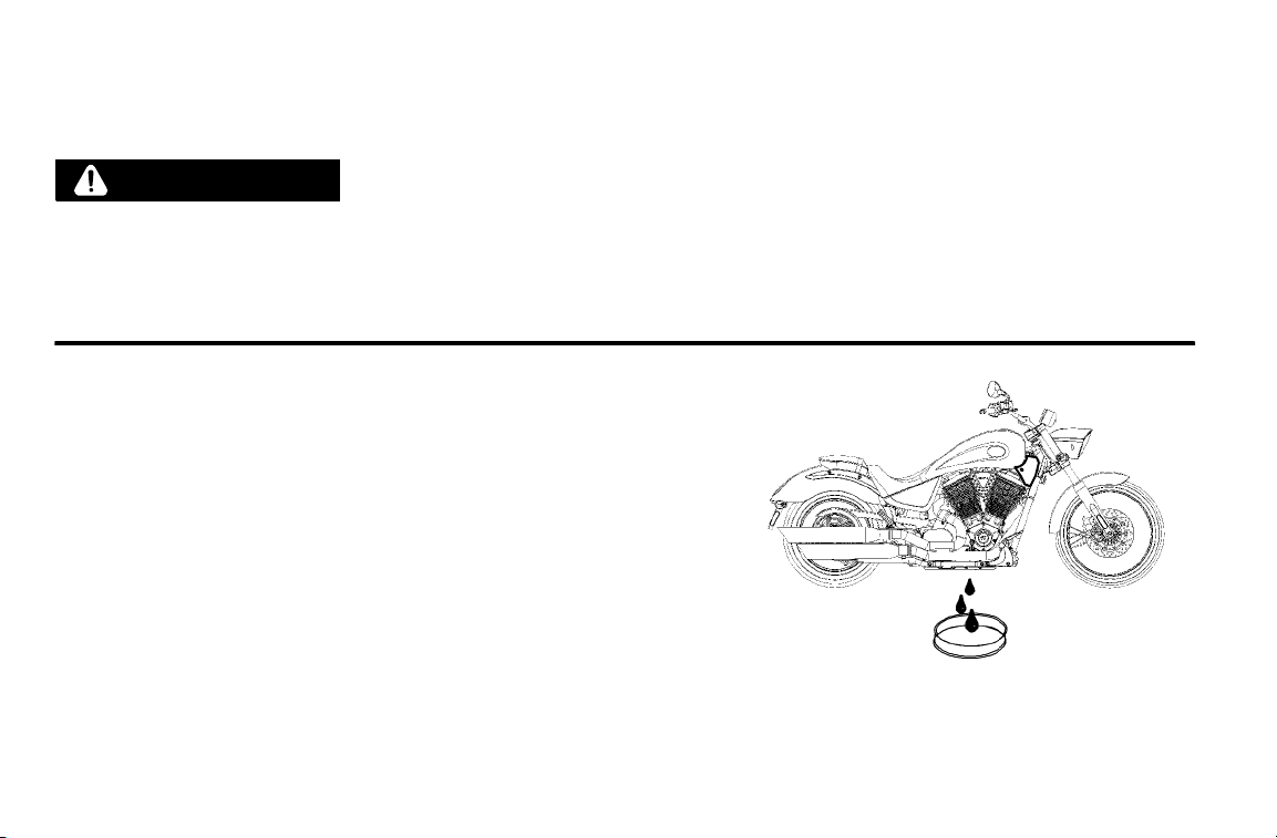
MAINTENANCE
Engine Oil
Change Engine Oil and Oil Filter
WARNING
A hot engine or hot exhaust pipes can be hazardous. The engine and exhaust pipes are hot for some time
after the engine is stopped. Touching the engine or exhaust pipes while hot can cause serious burns.
Allowing flammable materials to contact a hot engine or exhaust pipes may cause a fire. Park the
motorcycle where people will not touch the engine or exhaust pipes and where it is not near flammable
materials.
1. Start and run the engine until it reaches normal operating
temperature. Stop the engine.
2. Securely support the motorcycle on the sidestand.
3. Place a drain pan under the drain plug and oil filter.
4. Remove the drain plug and seal using the universal tool
(provided under the left side cover) or a good quality 6mm
hexagonal socket. Allow the oil to drain completely.
5. Use an oil filter wrench to slowly loosen the filter. Allow oil
in the filter to drain before removing the filter.
6. Reinstall the drain plug with a new seal.
Torque: 15 ft-lbs (20 Nm)
7. Clean any residue or debris from oil filter mounting plate and
threads.
88
Page 94

MAINTENANCE
Engine Oil
Change Engine Oil and Oil Filter
8. Make sure the new oil filter gasket is properly seated in the oil filter, and apply a thin film of clean engine oil to
the gasket. S crew the new filter on until the gasket contacts the filter mounting plate. Tighten the filter by hand
an additional 3/4 turn.
9. Fill the crankcase through the oil fill cap with about 8.75-9.0 pints (4.0-4.25 liters) of oil. We recommend the
use of only VICTORY Brand Semi-Synthetic 20W-40 Motor Oil or an equivalent oil designed for use with wet
clutches (such as those with a JASO MA rating).
10. Reinstall the oil fill cap and then start and run the engine until it reaches normal operating temperature.
Caution
After an oil change, the low oil pressure indicator remains illuminated longer than usual before going out.
Revving the engine while the low oil pressure indicator is illuminated can damage the engine.
11. Stop the engine and make sure there are no leaks around the drain plug and oil filter. Check the oil level and
adjust if needed.
Notice Recycle used oil and oil filter in accordance with local regulations.
89
Page 95

MAINTENANCE
Engine Oil
Check Engine Oil Level
1. With the transmission in neutral, start and run the engine for
several minutes.
2. Shut the engine off and wait for 3-5 minutes.
3. With the engine at normal operating temperature, straddle the
motorcycle on level ground and bring it to a vertical position.
Remove the oil fill cap and wipe the dipstick clean. Reinstall the
dipstick and turn the cap clockwise until it seats.
4. Remove the dipstick again and note the oil level.
5. If necessary, add or remove oil to bring the l evel into the area on
2
the dipstick, above the ADD mark and below the FULL mark
(see page 53). Repeat steps 1-2 each time you adjust the oil level.
1. Oil Fill Cap/Dipstick
2. ADD Mark
3. FULL Mark
WARNING
Do not operate the motorcycle with the oil level above the FULL mark or below the ADD mark. Operating
the engine with too much or too little oil can cause serious engine damage or engine seizure, resulting in
loss of control of the motorcycle.
1
3
90
Page 96

Inspect Air Filter
The standard VICTORY air filter element is a dry paper design and
does not require the use of air filter oil.
Notice Inspect the air filter often if riding in unusually wet or dusty
conditions.
1. Remove the air filter access cover and air filter element
using the universal tool provided under the left side cover
(see page 142).
2. To remove debris from the element, use low-pressure air and
blow from the rear forward.
MAINTENANCE
2
1
WARNING
Wear face protection when using pressurized air.
3. Apply a small amount of lubricant to the edge of the air filter
element frame and reinstall the element and access cover . Do not
over-tighten the access cover screws.
1. Air Filter Access Cover
2. Air Filter Element
91
Page 97

MAINTENANCE
Drive Belt
Check Drive Belt Condition
Replace the drive belt if it is cracked or has broken teeth or frayed edges. No matter its condition, the drive belt
should be replaced at periodic intervals (see the VICTORY Service Manual or an authorized VICTORY dealer). DO
NOT attempt to check belt tension if the belt has been exposed to rain or washing within a 24 hour period or if the
belt is hot from riding. Allow the belt to cool down to ambient temperature before measuring belt tension. Replace
drive belt and both sprockets as a set if drive belt has over 5,000 miles (8,000 km) of service at the time of damage
or failure.
Check Drive Belt Tension
This procedure involves using the belt tension gauge, part no. PV-43532,
which is designed specifically for measuring drive belt tension.
3
Before beginning this procedure:
S Make sure the drive belt is dry and at room temperature.
S Make sure the rear suspension is properly adjusted (see Adjust Rear
Shock Absorber, page 100).
92
1. Belt Tension Gauge
1
2. Small O-Ring
3. Base
4. Plunger
2
4
Page 98
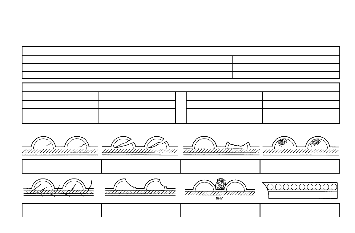
MAINTENANCE
Drive Belt
Check Drive Belt Tension
Drive Belt Deflection (with 10 lbs. of force)
VEGAS LOW VEGAS / VEGAS 8-BALL / ALL KINGPIN
New drive systems (new belt & sprockets) 5 mm +/- - 0.5 mm (13/64″ +/- - 1/64″) 12 mm +/-- 1 mm (15/32″ +/-- 1/32″)
After 500 miles on drive system 6 mm +/-- 0.5 mm (15/64″ +/- - 1/64″) 12 mm +/- - 1 mm (15/32″ +/- - 1/32″)
The following data is provided for use with a Sonic Tension Meter. Follow the instructions provided with the meter.
Required Data Required Data
Span 658.3mm
Belt width 28mm Tension (after 500 miles) 48.3 Hz
Belt mass constant 7.9
Drive Belt Wear Analysis
Tension (new belt) 50.6 Hz
Internal tooth cracks (hairline):
OK to run, but monitor condition
Fuzzy edge cord:
OK to run, but monitor condition
External tooth cracks:
Replace belt
Hook wear:
Replace belt
Missing teeth:
Replace belt
Replace belt if damage is on edge
Stone damage:
Chipping (not serious):
OK to run, but monitor condition
Bevel wear (outboard edge only):
OK to run, but monitor condition
93
Page 99
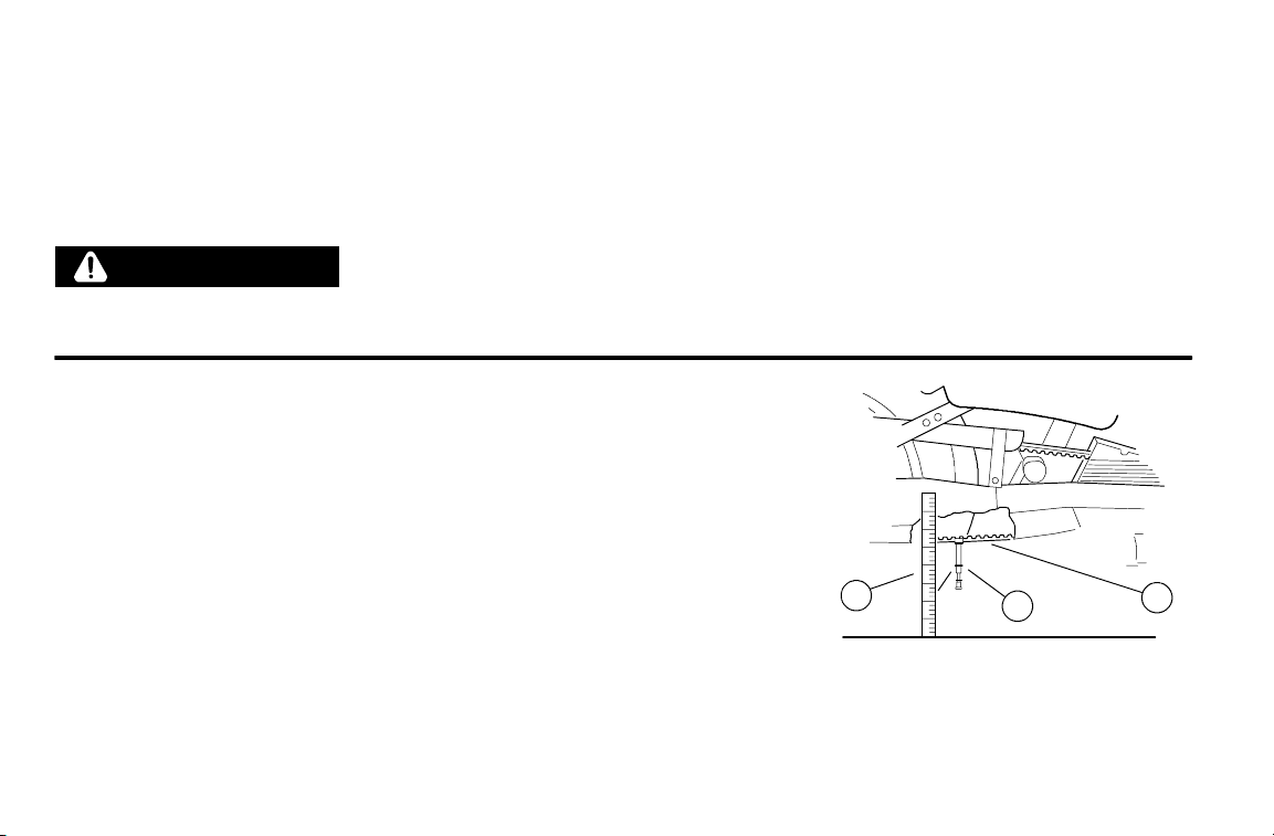
MAINTENANCE
Drive Belt
Check Drive Belt Tension
1. Place the transmission in Neutral and lift the rear wheel off t he ground
with an appropriate motorcycle lift or a block of wood or steel placed
securely under the frame.
WARNING
Care should be taken to be sure the motorcycle will not tip or fall while elevated. Severe personal injury
or death may occur if the motorcycle tips or falls.
2. Position the small O-ring on the belt tension gauge directly over
the 10 lbs. mark on the plunger as shown.
3. Place a tape measure or rule next to the drive belt as shown.
94
3
1. Drive Belt
2. Belt Tension Gauge
2
3. Rule
1
Page 100

Drive Belt
Check Drive Belt Tension
4. Place the base of the tension gauge bracket squarely against the
lower strand of the drive belt halfway between the front and rear
drive sprockets. Use the tape measure or ruler and record the
position of the base of the tension gauge bracket. This position
represents zero force.
5. Push the plunger upward until the small O-ring touches the
tension gauge body. Make s ure the tension gauge is seated
squarely against the drive belt, and record the position of the base
of the tension gauge bracket. This position represents 10 lbs.
force.
6. Calculate the difference between the zero force position and the
10 lbs. force position you recorded. Refer to the chart on page 93
for belt specifications.
7. Belt deflection must be measured and adjusted with the belt at
the tightest spot. Measure the belt deflection in 4 spots by
rotating the wheel 90 degrees in the forward direction between
measurements. Adjust belt tension as necessary. See page 96.
MAINTENANCE
Important Drive Belt Deflection
Information
S Measure / adjust belt deflection at tightest
spot
S Belt and sprockets must be clean, dry,
and at room temperature for accurate
deflection measurement
S Lowering kits affect belt deflection speci-
fications. Consult an authorized Victory
dealer if a lowering kit is installed on your
motorcycle.
S When a new drive belt is installed, tension
must be adjusted after 500 miles to ensure maximum belt service life.
95
 Loading...