

Polaris Vac-Sweep 3900 Sport, Vac-Sweep P39 Owner's Manual

TL-875 Rev D
3900 Sport/P39
OWNER’S MANUAL
ENGLISH | FRANÇAIS | ESPAÑOL
Page 2
Important Information
• Before installing the cleaner, make sure the pool filter is clean.
• New plumbing lines should be flushed out before installing the cleaner.
• The Polaris should not be used to remove plaster dust in new pools.
• Disconnect the cleaner before cleaning or backwashing the pool filter. After cleaning, let the
filtration system run for at least five (5) minutes before re-connecting the cleaner.
• Always remove the Polaris from the pool before super oxidation or chlorination treatments.
English
WARNING
To avoid risk of injury, do not handle the Polaris while it is operating, except when checking the
wheel RPM. Always remove the cleaner before swimmers enter the pool.
For customer service or support:
• Please mail Warranty Card immediately.
• For on-line support: www.polarispool.com
• To contact Polaris: US
Customer Service
2620 Commerce Way
Vista, CA 92081-8438
1-800-822-7933
Canada
2115 South Service Road West, Unit 3
Oakville, Ontario • Canada L6L 5W2
1-888-647-4004
CAUTION: USE OF THE POLARIS IN A VINYL LINER POOL
Certain vinyl liner patterns are particularly susceptible to rapid surface wear or pattern removal caused by objects coming into contact
with the vinyl surface, including pool brushes, pool toys, oats, fountains, chlorine dispensers, and automatic pool cleaners. Some
vinyl liner patterns can be seriously scratched or abraded simply by rubbing the surface with a pool brush. Ink from the pattern can
also rub off during the installation process or when it comes into contact with objects in the pool. Zodiac Pool Systems, Inc. is not
responsible for, and the Limited Warranty does not cover, pattern removal, abrasion or markings on vinyl liners.

Introduction
Congratulations on the purchase of your new automatic pool cleaner, and thank you for
choosing Polaris. The Polaris 3900 Sport/P39 is designed to give you years of dependable
and efficient service.
Page 3
Like most mechanical devices, it will require periodic adjustments, routine maintenance, and
the replacement of certain hardworking parts. Please have the cleaner checked occasionally
by your local Polaris dealer or service center.
Always insist on genuine Polaris replacement parts. Non-Polaris parts are not made to our
specifications. They may have an adverse effect on the operation of your Polaris or may even
damage it.
For best results, the cleaner should be installed by a pool professional. For those with
experience and confidence in handling plumbing and mechanical equipment, installation is
outlined in this manual.
Polaris 3900 Sport/P39 Components
1. SuperBag (Double) All-Purpose Zippered Bag
2. Cleaner Body
3. Sweep Hose
®
4. Tail Sweep Pro
5. Feed Hose
(with Sweephose Scrubber)
7. Back-up Valve
8. Feed Hose Connector
9. In-Line Filter with Filter Screen
10. Quick Disconnect with Universal Wall Fitting
®
11. UWF
Restrictor Disks, Red and Blue
English
6. Hose Floats
1
6
5
2
3
4
9
7
8
10
11
Page 4
2-3' apart
1.5 to 3' apart
Quick Installation Instructions
1
English
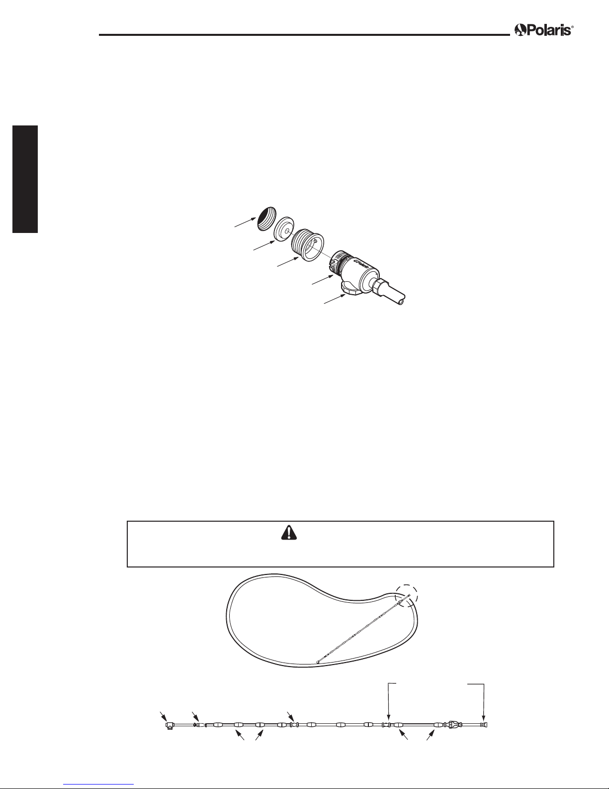
Install the Universal Wall Fitting
1. Turn on the filtration pump and flush out the plumbing line.Turn pump off.
®
2. Remove the Universal Wall Fitting (UWF
into the return opening with the blue restrictor disk in place.
3. Turn the Quick Disconnect clockwise into the UWF and pull away to secure. The Quick
Disconnect will click into place.
Dedicated
Return Line
Restrictor Disk
UWF
Quick Disconnect
Pressure Relief Valve
) from the Quick Disconnect and screw it
2
Adjust Feed Hose To Fit Pool Length
1. Measure the deepest part of the pool. Cut leader hose from the end that attaches to the
feed hose (away from the back up valve) so length is equal to the greatest depth of the
pool.
2. Attach leader hose to feed hose and connect hose to the pool wall at the return line.
Extend hose to farthest point of pool. The hose end must be within 6 inches – longer or
shorter – of the farthest point. See diagram below.
If hose is too long: Separate hose at center swivel. Cut half of the overage from each
10-foot feed hose section that attaches to the center swivel.
If hose is too short: Add a feed hose section (part #9-100-3104), a swivel (part #D20)
and two (2) hose nuts (part #D15). Adjust to proper length.
Each feed hose section should be equal in length after adjustments.
3. After adjusting the length, position the hose floats as shown.
CAUTION
Use caution when cutting the hose to prevent injury inflicted by the cutting tool.
Furthest
oint
In-Line
F
Filter
Center
Swivel
Feed Hose Floats
Return
Line
Leader Hose
Length = Max. Depth
Leader Hose Floats
3
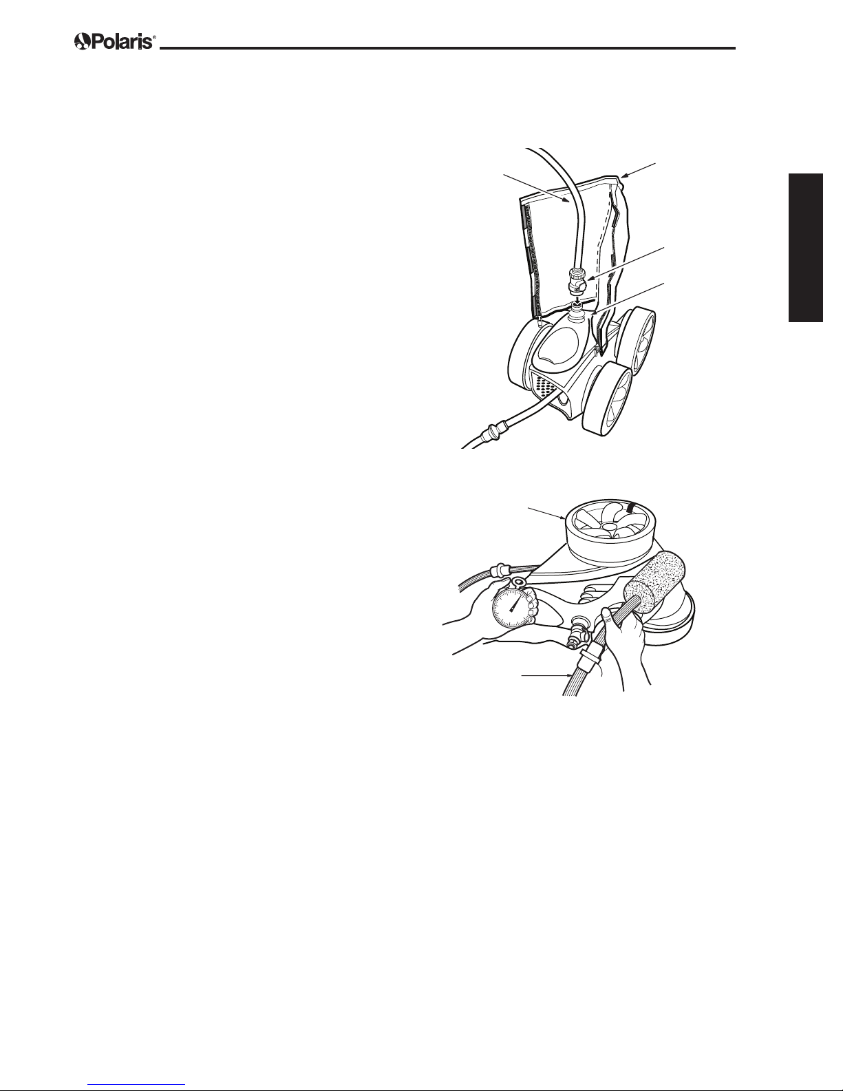
Bag
Assemble the Cleaner
1. Attach the feed hose connector
to the feed pipe by pressing it
down firmly until it locks.
Page 5
Hose
English
4
2. The filter bag is packaged in
the collar area on the vacuum
tube. Pull out the bag, separate
the velcro strips, wrap it around
the hose and resecure with
velcro strips.
3. Turn on the pool filtration
pump and allow it to prime
before turning on the booster
pump. (Refer to booster pump
manufacturer’s instructions for
booster pump priming time.)
Check for Proper RPM
Before operating the Polaris, check
for proper wheel revolutions per
minute (RPM).
For maximum efficiency, the cleaner
should operate between 30 and 36
RPM.
1. Mark the single-wheel
side tire.
Feed Hose
Connector
Feed
Pipe
Single-wheel Side
2. Turn pump on, hold cleaner
below water level and count
wheel revolutions for one minute.
If count is not in target range,
refer to Adjusting the Wheel
RPM in the Troubleshooting
section for more information.
Sweep Hose
Page 6
6
93
Fine Tuning The Cleaner
English
When operating correctly, the cleaner vacuums, sweeps and scrubs all surfaces randomly
throughout the pool. Approximately every three (3) minutes the cleaner goes into back-up mode.
This action pulls the cleaner away from pool obstacles and increases its random pattern.
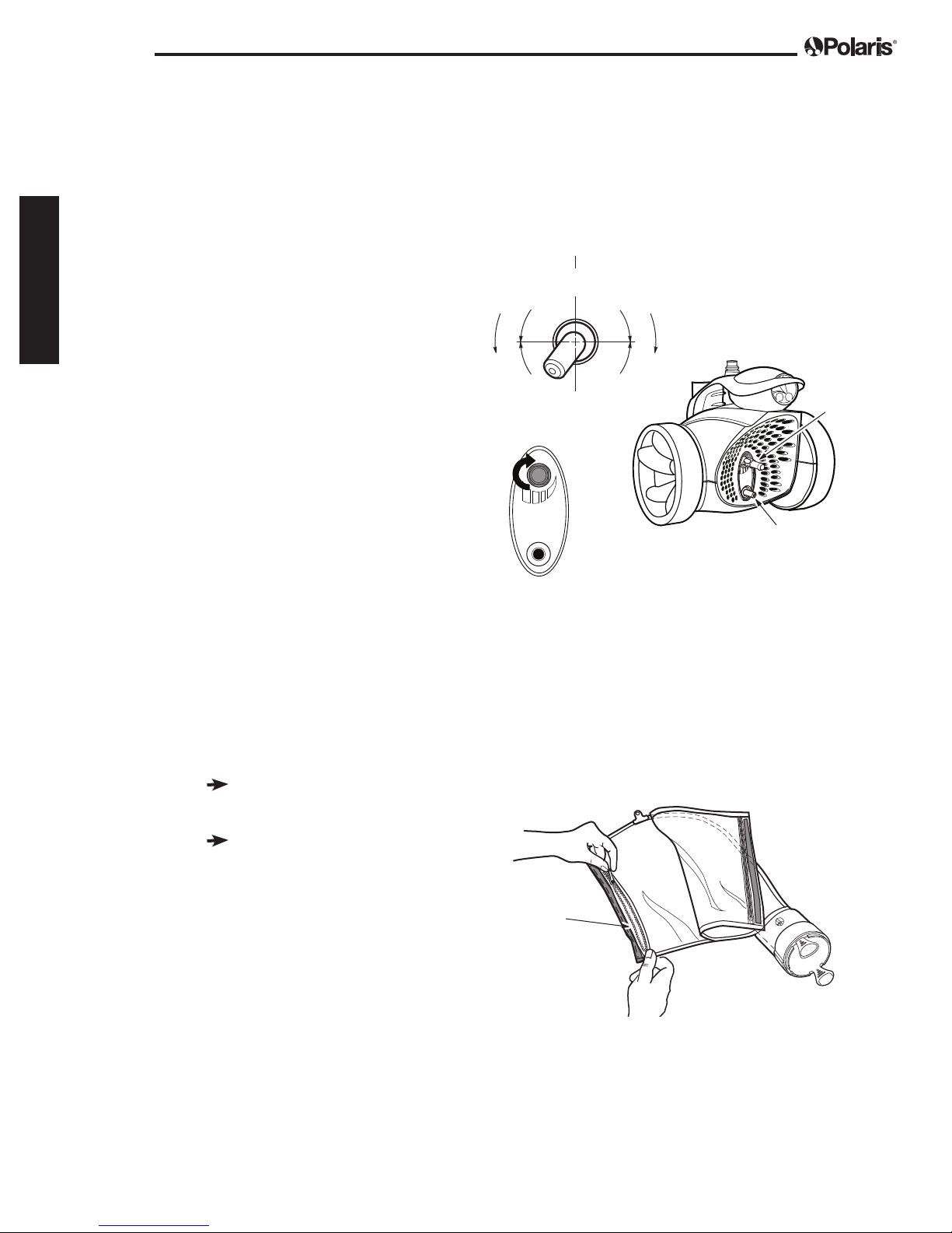
Thrust Jet Adjustment
The thrust jet powers the direction of
the cleaner. Factory position is seven
f
e
L
t
i
n
U
s
e
h
e
s
r
c
u
n
I
P
h
e
s
U
12
s
e
s
a
n
i
t
C
l
i
R
m
i
b
g
i
n
h
g
t
P
u
s
t
(7) o’clock but, depending on the
pool, other settings can be helpful to
improve cleaner coverage.
D
e
c
r
e
a
s
e
7
g
n
i
b
m
i
l
s
C
Sweep
Hose
Jet
Sweep Hose Adjustment
The sweep hose should move in a
gentle sweeping motion. To adjust
the motion, turn off the booster pump
and turn the sweep jet clockwise
to increase or counter-clockwise to
decrease the movement.
Thrust Jet
Routine Maintenance
Cleaning the Bag
Empty the filter bag when it is
half full, especially if the debris
load is sand.
It is easier to empty the filter
bag when it is dry. Alternate
between two (2) bags.
To remove the bag, detach the velcro
strips. Twist the bag collar and pull up to
free the bag from the cleaner. Unzip both
sides of the bag to remove the debris.
Zipper
Closure
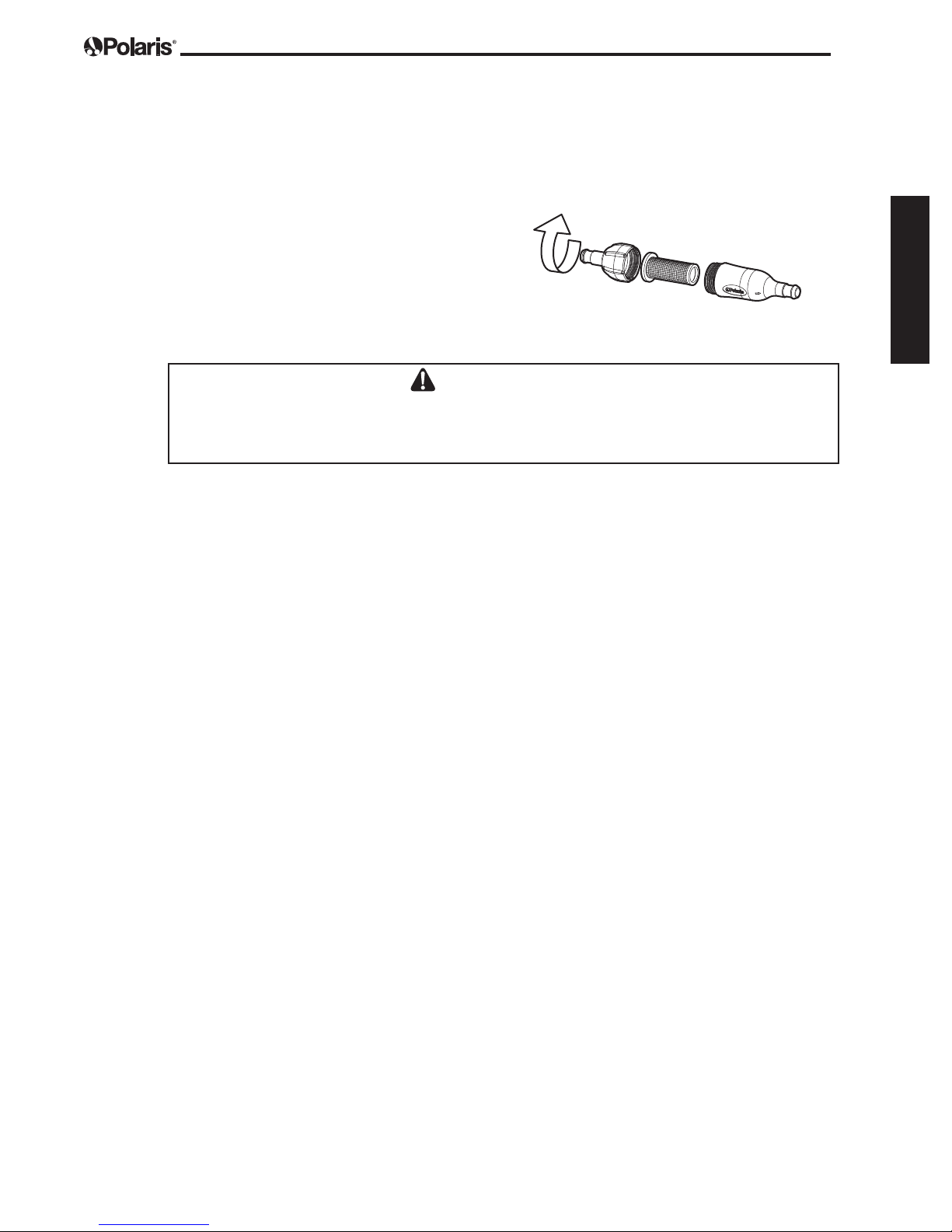
Cleaning the In-Line Filter
Screen
To clean the in-line filter screen, pull it out
of the filter assembly, rinse and press firmly
back into place.
CAUTION
Always disconnect the Polaris before cleaning or backwashing your pool filter to avoid potential
clogging or damage to the system. Allow the filtration system run for at least five (5) minutes
before re-connecting the cleaner.
Page 7
English
Storage and Winterizing
Never store the cleaner in direct sunlight. When storing for the winter, drain all the water from the
cleaner (freeze damage is not covered under the warranty). Use the Quick Disconnect to remove
the UWF from the pool wall. If necessary, use the UWF Removal Tool (part #10-102-00) available
from any Polaris dealer.
Page 8
English
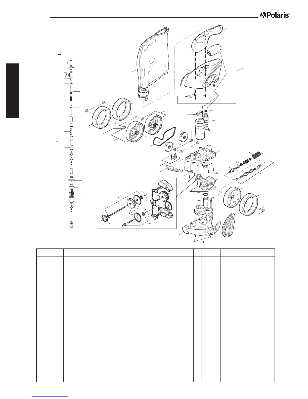
Exploded Parts Diagram
Pool
Wall
32
34
35
33
50/
50A
36
37
38
40
42
43
44
45
46
48
39
41
8
9
11A
11
21
47/47A
11A
4
1
9
11
10
12
17
16
5
3
51
52
11A
13
14
19
20
6
22A
22
6
7A
7
15
18
27
20
21
26/26A
2/2A
30
28
25
29
31/31A
9
10
To The
Polaris
49/49A
53
54
11A
23
24/24A
6
8
No. Part # Description Qty No. Part # Description Qty No. Part # Description Qty
1 39-310 3900 Sport/P39 SuperBag* 1
2 39-003 3900 Top Housing Assembly 1
2A R0669900 P39 Top Housing Assembly 1
3 R0538000 Float, Head Kit 1
4 R0537900 Canopy 1
5 R0538100 Housing Top 1
6 C40 Screw, 10-32 x 3/8” SS
Pan Head 17
7 39-006 Vacuum Tube/Feedpipe Assy
with O-Ring 1
7A 48-141 O-ring, Feed Hose Connector 1
8 39-008 Hubcap 3
9 48-232 WideTrax® Tire, Black* 3
10 48-036 Wheel Lock Screw 3
11 39-410 Double-Side Wheel w/B earing 2
11A 9-100-1108 Ball Bearing 8
12 39-126 Chain* 1
13 39-420 Wheel Sprocket Assy w/Bearing 2
14 39-602 Wheel Spacer 2
15 39-100 Frame (Warranty only) 1
16 39-111 Bumper 1
17 39-120 Chain Tensioner Kit 1
18 39-430 Rear Axle Block Assy 1
19 39-440 Front Axle Block Assy 1
20 48-045 Screw, 10-32 x 7/8” SS
Pan Head with Star Washer 4
21 39-200 Gearbox Assembly 1
22 39-300 WMS Assembly with O-Ring 1
22A R0544000 O-ring WMS Upper to
Vactube Interface
23 39-005 Rear Housing 1
24 39-004 3900 Bottom Housing 1
24A R0669700 P39 Bottom Housing 1
25 39-401 Single-Side Wheel 1
26 B16 Sweep Hose Attach Clamp, Black 1
26A B15 Sweep Hose Attach Clamp, Gray 1
27 39-021 Sweep Hose Wear Ring, Blue* 8
28 B25 Orifice Tip w/ Orifice Tip Guard 1
29 9-100-3105 Sweep Hose Scrubber* 1
29 R0522400 Sweep Hose Scrubber, 3 pk 1
30 R0540000 Tail Sweep Pro
®
, Bulk Box (18) 1
30 TSP10S TailSweep PRO, Strip Clip 12
31 39-500 Sweep Hose Complete, Black* 1
31A R0669600 Sweep Hose Complete, Gray* 1
32 10-112-00 UWF
®
Restrictor Disk, Red & Blue 2
33 6-550-00 Universal Wall Fitting, Black 1
33A 6-550-00 Universal Wall Fitting, Gray 1
34 10-108-00 UWF Restrictor Kit, Gray 1
35 6-505-00 O-Ring, UWF 1
36 9-100-9006 Pressure Relief Valve, Black 1
36A 9-100-9002 Pressure Relief Valve, Gray 1
37 D30 Quick Disconnect, UWF Black 1
37A D29 Quick Disconnect, UWF Gray 1
38 D16 Nut, Feed Hose, Black 10
38A D15 Nut, Feed Hose, Gray 10
39 9-100-9005 UWF Connector Assy, Black 1
39A 9-100-9001 UWF Connector Assy, Gray 1
40 D44 Adapter Hose, 8-1/2” 1
41 48-080 In-line Filter Assy, Gray 1
41A 48-085 In-line Filter Assy, Black 1
42 48-222 Screen, In-line Filter 1
43 D11 Float, Feed Hose, Black 9
43A D10 Float, Feed Hose, Gray 9
44 D21 Swivel Ball Bearing, Black 3
44A D20 Swivel Ball Bearing, Gray 3
45 D47 Feed Hose, 10 ft., Black 2
45A D45 Feed Hose, 10 ft., Gray 2
46 D52 Leader Hose, 10 ft., Black 1
46A D50 Leader Hose, 10 ft., Gray 1
47 G62 Back-up Valve Kit, Black 1
47A G52 Back-up Valve Kit, Gray 1
48 G53 Mechanism for G52 1
49 48-240 Feed Hose Connector Assembly, Black 1
49A 48-140 Feed Hose Connector Assembly, Gray 1
50 G6 Feed Hose Assembly Complete, Black 1
50A G5 Feed Hose Assembly Complete, Gray 1
51 R0538200 Screw, Self Tapping, Canopy 3
52 R0537800 Chain Guard 1
53 R0547400 Turbine Gear Assy 3
54 R0547500 Drive Sprocket Assy 2
*Wear items not covered by warranty.

Troubleshooting
Page 9
If the cleaner regularly displays any of the following
actions, adjustments may be necessary to restore
performance. Refer to the exploded parts diagram
for part references.
Action: Cleaner hangs up on steps or other
obstacles for longer
than 3 minutes.
Solution: 1. Check the wheel RPM.
2. Verify the back-up valve is cycling.
Lift the valve out of the water and
watch the jet. It should come on and
go off.
3. Adjust the thrust jet.
4. Remove unnecessary pool hardware
or install a Ladder Guard Kit (part
#G21).
Action: Cleaner is sluggish, running with less
power than normal.
Solution: 1. Check the filter screen in the
in-line filter assembly and clean
if necessary.
2. Clean the skimmer basket, pump
basket, and pool filter.
3. Check the hoses, hose connections,
and swivels for leaks that could cause
loss of water pressure.
4. Check the wheel RPM. If
below 30 RPM, see Adjusting the
Wheel RPM to increase flow to
cleaner.
Action: Cleaner races around the pool and/or
does not make contact with the pool
bottom.
Solution: 1. Check the wheel RPM. If
more than 36 RPM, see Adjusting
the Wheel RPM
to reduce flow.
2. Verify the back-up valve is cycling.
Lift the valve out of the water and
watch the jet. It should come on and
go off.
Action: Cleaner doesn’t back up.
Solution: 1. Verify the back-up valve
is cycling. Lift the valve out of the
water and watch the jet.
It should come on and go off.
2. Check the wheel RPM.
If not in 30-36 RPM range, see
Adjusting the Wheel RPM.
3. If the filter bag is full, empty
or replace it.
4. Make sure feed hose
is floating.
Action: Cleaner only turns in one direction.
Solution: 1. Adjust the thrust jet.
2. Make sure feed hose
is floating.
Action: Feed hose becomes tangled.
Solution: 1. Remeasure the hose to verify that it is
adjusted to the proper length for the
pool.
2. With the cleaner operating, check that
the swivels and
hose connections turn freely.
3. Make sure the feed hose
is floating.
4. With the Polaris operating,
hold the cleaner under water and
verify that all three (3) wheels are
turning together.
Action: The front end of the cleaner
lifts all the time.
Solution: 1. Check the wheel RPM.
If not in 30-36 RPM range, see
Adjusting the Wheel RPM.
2. Adjust the thrust jet
downward.
3. Verify the back-up valve is cycling.
Lift the valve out of
the water and watch the jet.
It should come on and go off.
English
4. Check for water inside the cleaner
float.

Page 10
Action: Sweep hose is sucked into the
Solution: 1. Make sure the opening at the end
2. Adjust the sweep hose to a gentle
3. Check the wheel RPM. If
English
4. Add a sweep hose weight
Action: The cleaner does not clean the
Solution: 1. Verify that feed hose reaches within
2. Adjust thrust jet to improve coverage.
Action: The cleaner is running in circles on
Solution: 1. Check for water inside the cleaner
2. Check the filter bag, if full it can weigh
3. Check the hose floats to make sure
vacuum tube.
of the sweep hose is not blocked by
the sweep hose scrubber. Replace
scrubber if it is worn or missing.
sweeping motion.
more than 36 RPM, see Adjusting
the Wheel RPM to reduce flow.
(part #B2).
entire pool.
6 inches of the farthest point of the
pool. If not, order a new hose section
from your Polaris dealer.
its side.
float.
the cleaner down on one side.
they are spaced evenly.
Adjusting the Wheel RPM
If count is less than 30 RPM:
• If an adjustable valve is installed on the
cleaner line, open it completely so water can
flow freely to the Polaris.
• Check the filter screen in the in-line filter for
debris that restricts water flow.
• Clean the skimmer, filter and pump basket,
clearing debris that restricts
water flow.
• Check the hoses, connections and
swivels for leaks that cause loss of
water pressure.
• Remove the blue restrictor disk from
the UWF
If count is more than 36 RPM:
• Replace the blue restrictor disk in the UWF
with the red restrictor. If the flow is still too
high, unscrew the pressure relief valve until
the proper RPM is reached.
NOTE The pressure relief valve should only be
adjusted when a restrictor is installed.
• If an adjustable valve is installed on the
cleaner line, adjust it to reduce the water
flow to the cleaner.
®
.
4. Check the wheel RPM. If
more than 36 RPM, see Adjusting
the Wheel RPM to reduce flow.
 Loading...